

SunStar SPS/E-BS1202 Series, SPS/E-BR1202 Series User Manual
SSUUNNSSTTAARR MMAACCHHIINNEERRYY CCOO..,, LLTTDD..
User’s
Manual
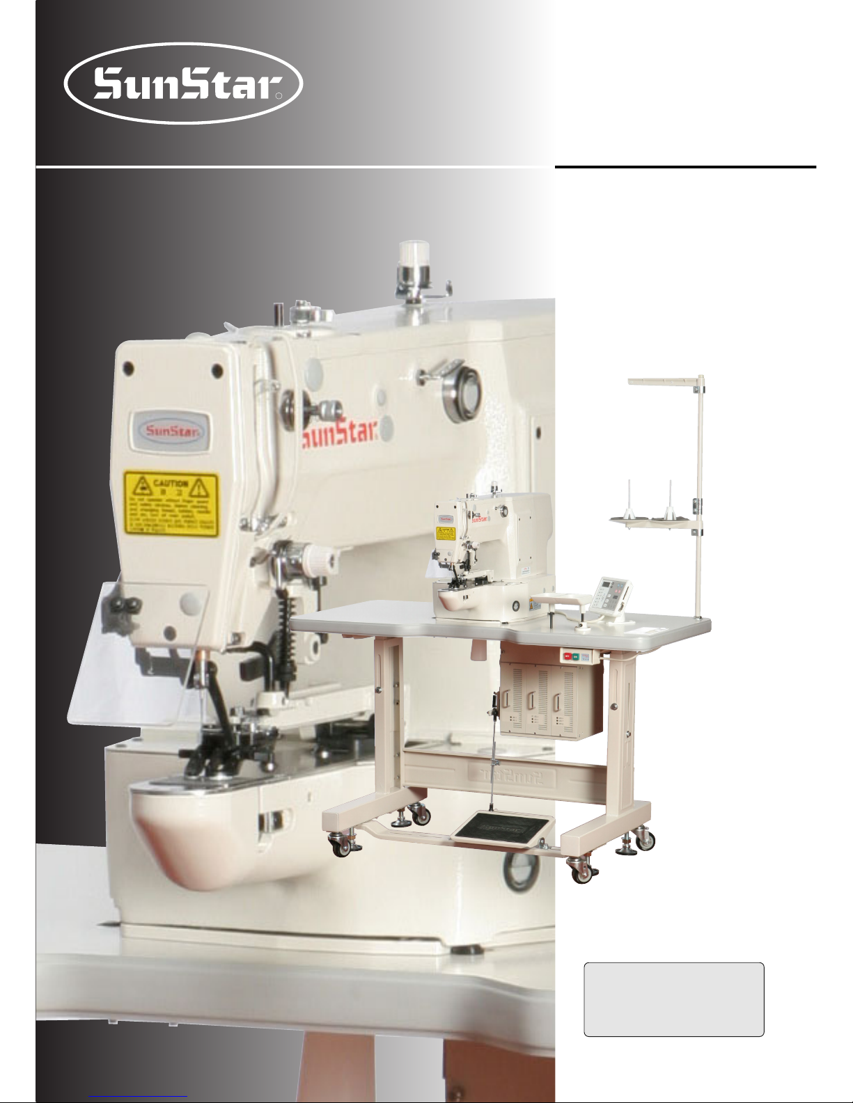
SPS/E-BS1202 Series
SPS/E-BR1202 Series
Electronically Controlled
Button Sewing Machine
(Mechanical Part)
R
MMMMEE--006600771133
1) FOR AT MOST USE WITH EASINESS,
PLEASE CERTAINLY READ THIS MANUAL
BEFORE STARTING USE.
2) KEEP THIS MANUAL IN SAFE PLACE
FOR REFERENCE WHEN THE MACHINE
BREAKS DOWN.

Best Quality
Best Price
Best Service
SSUUNNSSTTAARR MMAACCHHIINNEERRYY CCOO..,, LLTTDD..
R
1.
Thank you for purchasing our product. Based on the rich expertise and
experience accumulated in industrial sewing machine production, SUNSTAR
will manufacture industrial sewing machines, which deliver more diverse
functions, high performance, powerful operation, enhanced durability, and
more sophisticated design to meet a number of user’s needs.
2. Please read this user’s manual thoroughly before using the machine. Make
sure to properly use the machine to enjoy its full performance.
3. The specifications of the machine are subject to change, aimed to enhance
product performance, without prior notice.
4.
This product is designed, manufactured, and sold as an industrial sewing
machine. It should not be used for other than industrial purpose.

4
Contents
1. Machine Type and Specifications
..............................................................................
6
2. Safety Rules
.........................................................................................................................
7
2.1) Safety Stickers
...................................................................................................................
7
2.2) Machine Delivery
..............................................................................................................
8
2.3) Machine Installation
..........................................................................................................
9
2.4) Machine Operation
............................................................................................................
9
2.5) Repair and Maintenance
..................................................................................................
10
2.6) Devices for safety
............................................................................................................
10
2.7) Location of Safety Labels
................................................................................................
11
3. Assembly
............................................................................................................................
12
3.1) Name of Machine Parts
...................................................................................................
12
4. Machine Installation
.......................................................................................................
13
4.1) Installation Environment
.................................................................................................
13
4.2) Electricity Environment
................................................................................................
13
4.3) Table Installation
.............................................................................................................
13
4.4) Machine Installation
........................................................................................................
14
4.5) Accessory Installation
.....................................................................................................
16
5. Machine Operation
.........................................................................................................
17
5.1) How to supply oil
............................................................................................................
17
5.2) How to grease
..................................................................................................................
17
5.3) Needle
..............................................................................................................................
18
5.4) Thread
..............................................................................................................................
18
5.5) Pedal Operation
...............................................................................................................
20
6. Maintenance
.......................................................................................................................
21
6.1) Adjustment of Needle Bar Height
..................................................................................
21
6.2) Adjustment of Needle and Hook
....................................................................................
21
6.3) Adjustment of Lower Shaft Gear and Oscillating Shaft (BS : Semi-rotary)
.................
22
6.4) Adjustment of Shuttle Upside Spring Position (BS : Semi-rotary)
...............................
23
6.5) How to adjust the ascending range of button clamp
......................................................
23
6.6) How to adjust the button clamp holder tension
..............................................................
24
6.7) Adjusting the parts of thread release
...............................................................................
24
6.8) Adjustment of Wiper-related Parts
.................................................................................
25
6.9) Adjustment of Trimmer-related Parts
.............................................................................
26
6.10) Adjustment of Thread Volume on Bobbin
...................................................................
28

5
6.11) Adjustment of Hand Pulley Device
..............................................................................
29
6.12) Assembly and Adjustment of Direct Drive Motor
.......................................................
29
6.13) Setting up the X-Y Origin
.............................................................................................
29
6.14) How to adjust the feeding plate
...................................................................................
30
6.15) Checking the setting position of button clamp
.............................................................
30
6.16) How to set up the button clamp adjusting plate
...........................................................
31
6.17) How to attach the spacer spring plate
...........................................................................
31
6.18) Oil Supply
......................................................................................................................
31
6.19) Cleaning
.........................................................................................................................
34
6.20) Handling of Waste Oil
...................................................................................................
34
7. Cause of Breakdown and Troubleshooting
........................................................
35
8. Pattern List
.........................................................................................................................
37
9. Drawing of Table
..............................................................................................................
38
10. GAUGE LIST
....................................................................................................................
39
11. OPTION LIST
...................................................................................................................
39
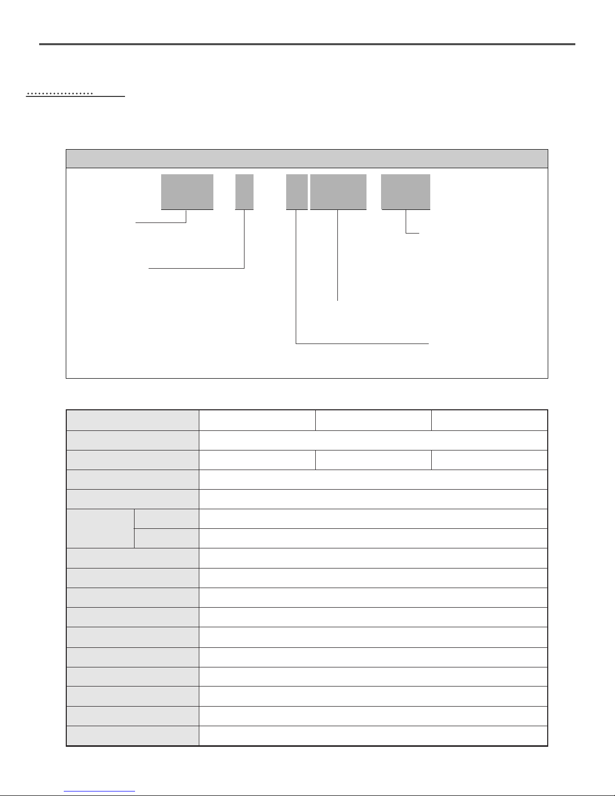
Name of Model
Speed
Button Size
Wiper Specification
Needle
Button Clamp Lift
No. of Patterns
No. of Stitches
Enlargement / Reduction
Memory
Proper Temperatare of machine running
Proper Temperatare of machine running
Main Motor
Power consumption
Power
6
11
Machine Type and Specifications
② Series Type
E:Motor direct drive-type
① SunStar
Pattern
System
⑤ Button Type
01 : Small-Size Button
(Mechanical Type Wiper)
02: Large-Size Button
(Mechanical Type Wiper)
03 : Small & Large Size Button
(Solenoid wiper Type Wiper)
④ Button S/M Model Name
③ Bartack Sewing Machine
Name
S : Shuttle Hook
R : Rotary Hook
SPS / E- B1202
Max. 2,700spm (Standard : 2,500spm)
Mechanical Type Wiper
DP×17 #14
shuttle hook
2× rotary hook
Max. 13mm
Max. 99 Patterns (Standard: 33 Patterns)
Max. 10,000 Stitches
20%~200%
P-ROM
5℃~40℃
20%~80%
500W direct drive AC servo motor×1 / step motor×3
600VA
1ф : 100~240V / 3ф : 200V~440V, 50/60Hz
Bartack Sewing Machine Model
SPS/E(R)1202-01 SPS/E(R)1202-02 SPS/E(R)1202-03
ф8~ф20mm ф8~ф32mm ф8~ф32mm
Hook
BS
BR
7
22
Safety Rules
2.1) Safety Stickers
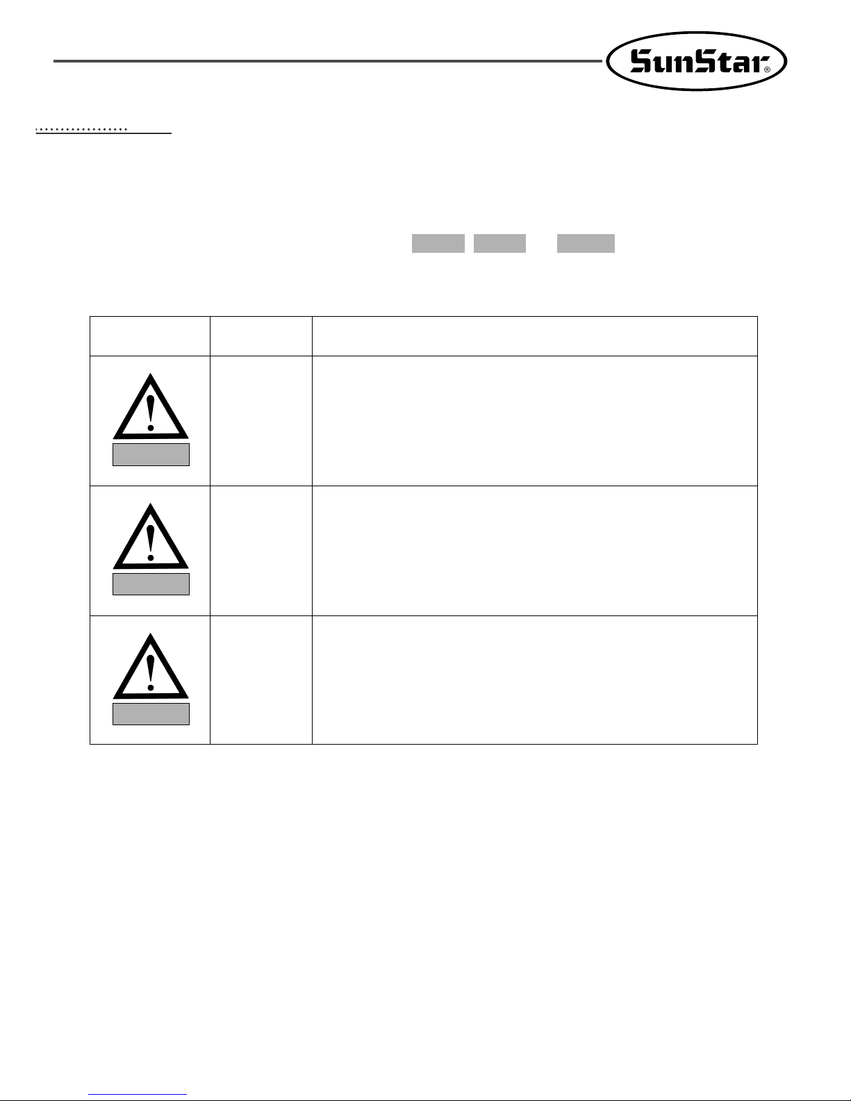
The safety stickers in this user’s manual are divided into , , and . They indicate that if the
safety rules are not kept, injury or damage to machine might occur as a result.
WarningDangerCaution
No. Name
Description
Caution
Warning
Danger
Caution
If the machine is not properly handled, it may cause injury to
users or physical damage to the machine.
If the machine is not properly handled, it may cause death or
severe injury to users.
If the machine is not properly handled, it may cause death or
severe injury to users, and the urgency of the danger is very
high.
Warning
Danger
8
2.2) Machine Delivery
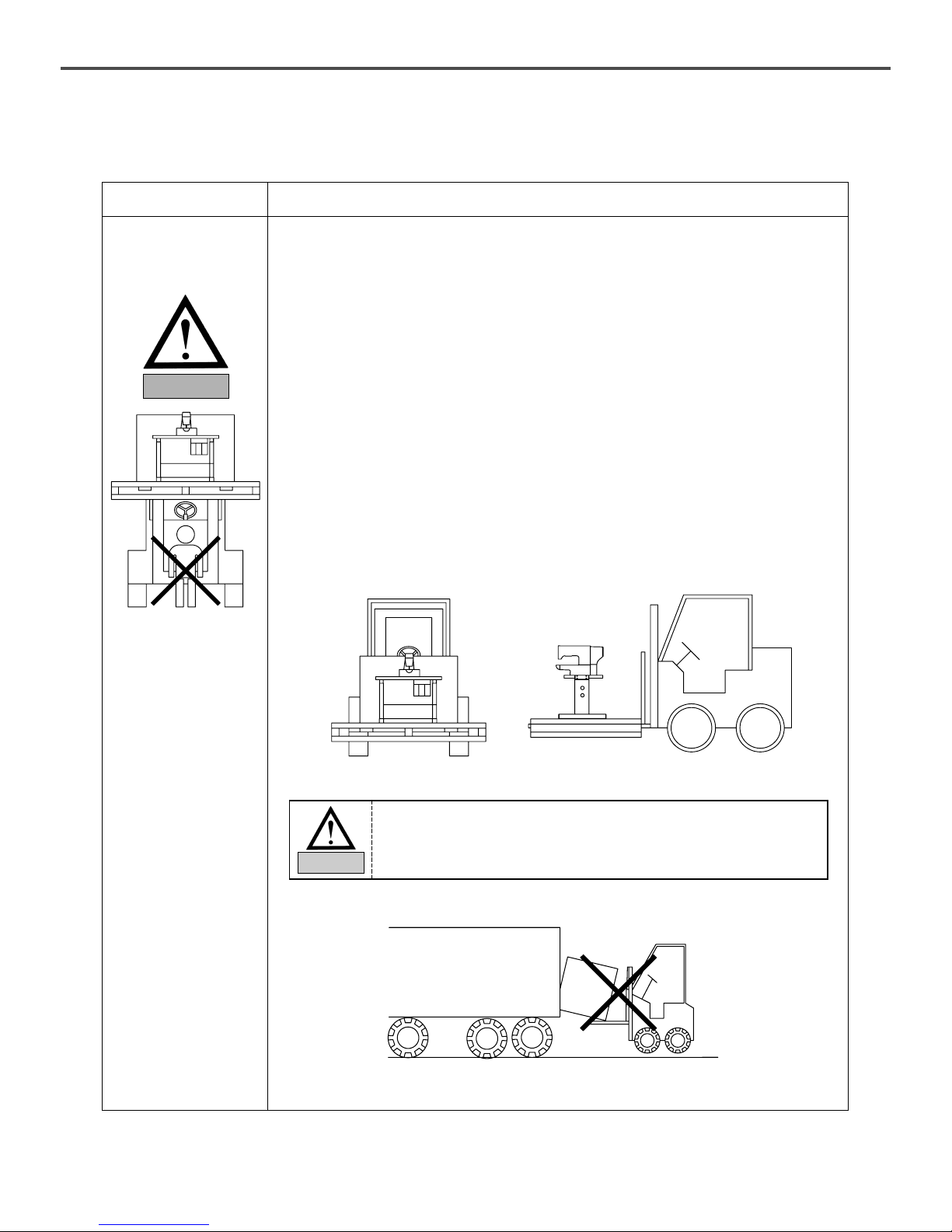
Danger
The machine delivery shall be conducted by the persons who are knowledgeable
about the safety instructions and rules. The following safety rules must be
observed:
2.2.1) Manual delivery
When the machine is delivered by persons, they shall wear special shoes and tightly hold
the machine on the left and right sides.
2.2.2) Forklift delivery
1) A forklift shall be big enough to endure the weight of the sewing machine and carry
the machine.
2) Use the palette when lifting the machine. Set the center of gravity of the machine
(center of the left and right sides) at the fork arm of the forklift and carefully lift the
machine.
Ban people from
standing under the
machine and remove
obstacles near the
machine.
Mark
Description
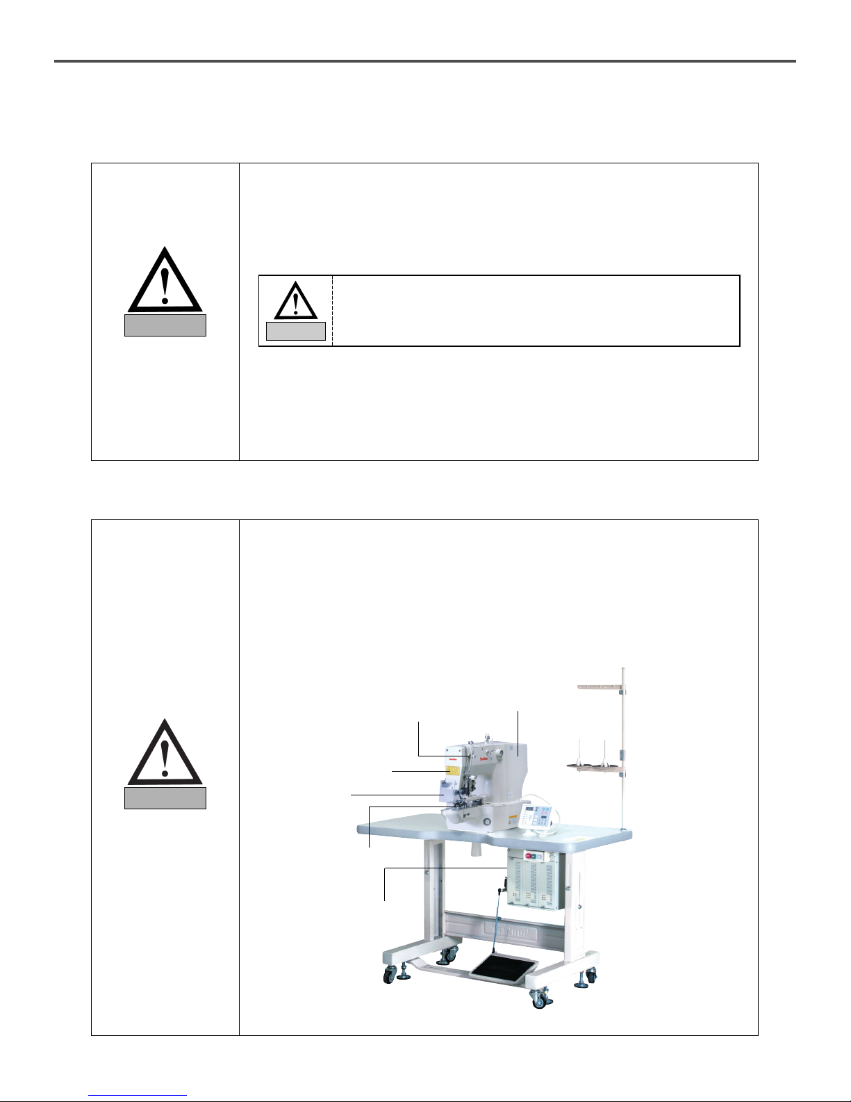
Make sure to maintain the balance of the machine when unloading the
machine by using a forklift or crane to prevent the deformation of the
machine or to prevent people from being exposed to danger.
Warning
9
Warning
2.3) Machine Installation
Caution
Depending on the installation environment, function errors, breakdown, or
other physical damage might result. Make sure to meet the following
conditions for machine installation:
1) The workbench or table where the machine is installed should be durable enough to
endure the weight of the machine (see the name plate).
2) Dust and humidity are the cause of machine pollution and erosion. Please install an air
conditioner and conduct regular maintenance of the machine.
3) Install the machine at the place where it is not exposed to direct sunlight (if the machine is
exposed to direct sunlight for a long time, it may cause discoloration or deformation).
4) Secure the space around the machine. Place the machine at least 50cm away from the
left, right, and rear walls to secure sufficient space for maintenance activities.
5) Explosion risk : To prevent possible explosion, immediately stop the machine
operation if there are inflammable materials in the air.
6) Lighting : The machine does not offer lighting devices. When necessary, install needed
lighting.
7) Overturn risk : Do not install the machine on the unstable stand or table. If the machine
drops, it may cause injury or severe impact on the machine. If the machine is suddenly
stopped or the external impact is imposed, the machine might be capsized.
2.4) Machine Operation
The machine body is attached with and stickers at each
dangerous part to emphasize safety instructions. With the full understanding
of the safety instructions, make sure to observe the following during machine
operation:
1) Before turning on the power, read this manual thoroughly and have a full
understanding of machine operation.
2) Get properly dressed. Long hair, necklace, bracelet, or wide sleeve might be fed into the
machine during operation. Wear slip-free shoes to prevent slipping on the floor.
3) Check the moving scope of machine before its operation to find out whether the scope
is proper.
4) Keep hands and head away from the machine parts where accidents might occur
(needle, hook, thread take-up lever, pulley, etc.) during operation.
5) Do not remove the safety cover which protects pulley and shaft during machine
operation for user’s safety.
6) Cut the power supply before disassembling the electric box such as the control box,
and double-check that the power switch is “Off.”
7) Make sure that the power switch is “Off”when the upper shaft is manually rotated.
8) Stop the machine when the needle is replaced or when inspecting the machine after
sewing work is done.
9) Make sure to follow the cautions below. Otherwise, physical damage to the machine
such as malfunction and breakdown might result:
- Do not put articles on the S/M table.
- Avoid using a crooked needle or the needle with damaged tip.
- Use the presser foot appropriate to working conditions.
WarningCaution
10
2.5) Repair and Maintenance
When machine repair is needed, it shall be conducted by SunStar A/S
engineers only who have finished the due training course.
1) For cleaning and repair, cut the main power supply. Wait for 4 minutes before starting
maintenance to make the machine completely discharged.
2) Do not modify the machine specifications or parts without substantial consultations
with SunStar. Otherwise, it may threaten safety during machine operation.
3) Use the parts manufactured by SunStar to repair or replace the machine parts during
A/S service.
4) When repairing is completed, re-install all the removed safety covers.
Danger
2.6) Devices for safety
ⓐ Safety label : It describes cautions during operating the machine.
ⓑ Thread take-up cover : It prevents from any contact between body and take-up lever.
ⓒ Motor Cover : It prevents from insertion of hands, feet or clothes by Motor.
ⓓ Label for specification of power : It describes cautions for safety to protect against
electric shock during rotating the motors. (Voltage input / use Hz)
ⓔ Finger guard : It prevent from contacts between a finger and needle.
ⓕ Safety plate : It protects eyes against needle breaks.
Caution
ⓐ
ⓕ
ⓔ
ⓓ
ⓑ
ⓒ
For main shaft motor and X,Y drive box, it takes 10 minutes before they
are completely discharged after the main power is cut.
Caution
11
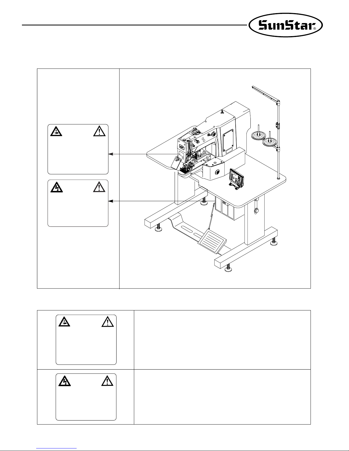
2.7) Location of Safety Labels
CAUTION
경고
Do not operate without finger guard and
safety devices. Before threading, changing
bobbin and needle, cleaning etc. switch off
main switch.
손가락 보호대와 안전장치 없이 작동하지
마십시오.
실, 보빈, 바늘교환시나 청소전에는 반드시
주전원의 스위치를 꺼 주십시오.
WARNING
경고
Hazardous voltage will cause injury.
Be sure to wait at least 360 seconds
before opening this cover after turn off
main switch and unplug a power cord.
고압 전류에 의해 감전될 수 있으므로 커버를
열 때는 전원을 내리고 전원 플러그를 뽑고 나
서 360초간 기다린 후 여십시오.
2.8) Type of Safety Labels
Do not operate without finger guard and safety devices. Before threading,
changing bobbin and needle, and cleaning, turn off the main switch.
Hazardous voltage will cause injury.
Be sure to wait at least 360 seconds before opening this cover after turn
off main switch and unplug a power cord.
CAUTION
경고
Do not operate without finger guard and
safety devices. Before threading, changing
bobbin and needle, cleaning etc. switch
off main switch.
손가락 보호대와 안전장치 없이 작동하지
마십시오.
실, 보빈, 바늘교환시나 청소전에는 반드시
주전원의 스위치를 꺼 주십시오.
WARNING
경고
Hazardous voltage will cause injury.
Be sure to wait at least 360 seconds
before opening this cover after turn off
main switch and unplug a power cord.
고압 전류에 의해 감전될 수 있으므로 커버를
열 때는 전원을 내리고 전원 플러그를 뽑고 나
서 360초간 기다린 후 여십시오.
12
33
Assembly
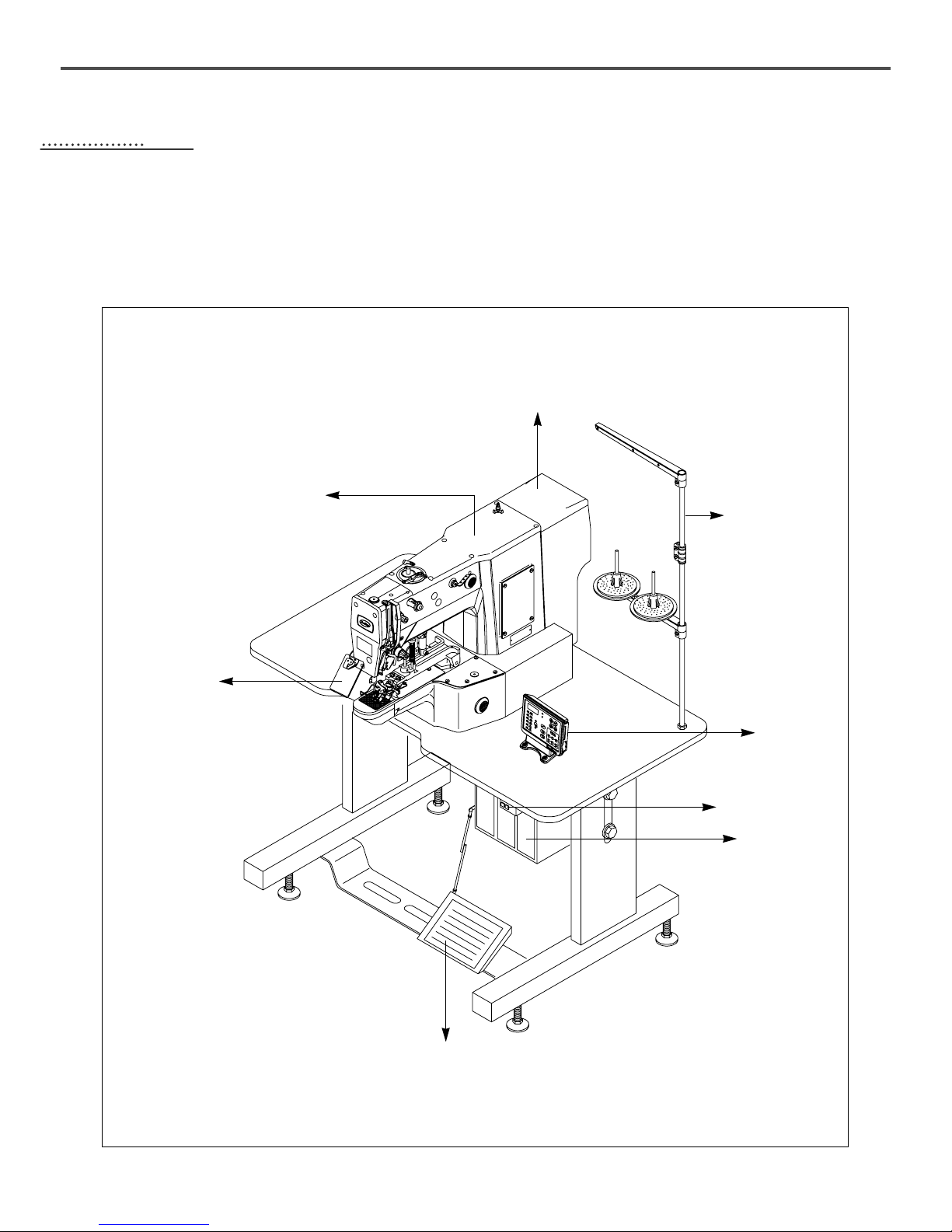
3.1) Name of Machine Parts
3.1.1) Name of Machine Parts
Power Switch
Thread Stand
Arm
Safety Plate
Motor Cover
OP Box
Control Box
Pedal
13
44
Machine Installation
4.1) Installation Environment
1) To prevent accidents stemming from mal-operation, do not use the machine if the voltage is 10% above the rated voltage.
2) To prevent accidents stemming from mal-operation, make sure to check if the air pressure is proper before using any air
pressure devices such as air cylinder.
3) Proper temperature during machine operation : 5°~ 40°C
4) Proper temperature during machine storage : -10°~ 60°C
5) Humidity : Relative humidity – within 20 ~ 80%
4.2) Electricity Environment
1) Power voltage
- The power voltage shall be within 10% of the rated voltage.
- It is recommended to use the power frequency within +/- 1% of the rated frequency (50/60Hz).
2) Noise of electromagnetic wave
- Do not share the power with the products which have either strong magnetic field or use high frequency. Make the
machine stay away from the products mentioned above.
3) Take care not to spill water and coffee on the machine.
4) Do not drop Control Box and the motor to the floor.
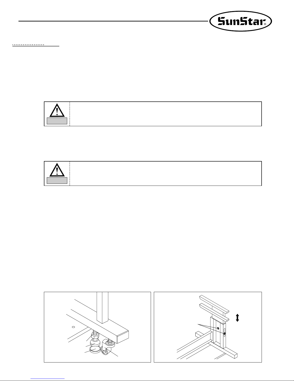
4.3) Table Installation
1) Table fixing
- Insert the shock absorbing rubber into the level adjuster and raise it until the caster freely moves.
- After the table is installed, tighten the nut to fix the level adjuster.
2) Table height adjustment
- Use the bolts attached to the table to adjust the height of the table to make sure that the users can smoothly and
conveniently work.
Nut
Level Adjuster
Shock Absorbing
Rubber
Caster
Bolt
To guarantee smooth operation of the product, the installation environment shall be prepared as
described in User’s Manual. Otherwise, unexpected damage might occur to the product.
Caution
The voltage shall be within 10% of the rated voltage.
Warning
 Loading...