

SunStar SPS/E-1306-GS-10, SPS/E-1306-GS-20, SPS/E-1507-GS-10, SPS/E-1306-GS-21, SPS/E-1306-GS-22 User Manual
...
1) FOR AT MOST USE WITH EASINESS,
PLEASE CERTAINLY READ THIS MANUAL
BEFORE STARTING USE.
2) KEEP THIS MANUAL IN SAFE PLACE
FOR REFERENCE WHEN THE MACHINE
BREAKS DOWN.
MMMMEE--110011002211
USER
’’
S MANUAL
R
SSuunnSSttaarr CCOO..,, LLTTDD..
SPS/E-1507 Series
Electronically Controlled
Pattern Sewing Machine
(Mechanical Part)


Best Quality
Best Price
Best Service
SSUUNNSSTTAARR CCOO..,, LLTTDD..
R
1.
Thank you for purchasing our product. Based on the rich expertise and
experience accumulated in industrial sewing machine production, SUNSTAR
will manufacture industrial sewing machines, which deliver more diverse
functions, high performance, powerful operation, enhanced durability, and
more sophisticated design to meet a number of user’s needs.
2. Please read this user’s manual thoroughly before using the machine. Make
sure to properly use the machine to enjoy its full performance.
3. The specifications of the machine are subject to change, aimed to enhance
product performance, without prior notice.
4.
This product is designed, manufactured, and sold as an industrial sewing
machine. It should not be used for other than industrial purpose.

4
Contents
1. MACHINE TYPE AND SPECIFICA TIONS
............................................................
6
1.1) Machine type
..........................................................................................................
6
1.2) Specifications of the machine
..............................................................................
7
2. SAFETY RULES
.........................................................................................................
8
2.1) Safety Stickers
.......................................................................................................
8
2.2) Machine Delivery
...................................................................................................
9
2.3) Machine Installation
............................................................................................
10
2.4) Machine Operation
..............................................................................................
10
2.5) Repair and Maintenance
....................................................................................
11
2.6) Devices for Safety
...............................................................................................
11
2.7) Location of Safety Labels
...................................................................................
12
2.8) Type of Safety Labels
.........................................................................................
12
3. ASSEMBLY
................................................................................................................
13
3.1) Name of Machine Parts
.....................................................................................
13
4. MACHINE INST ALLATION
....................................................................................
14
4.1) Installation Environment
.....................................................................................
14
4.2) Electricity Environment
.......................................................................................
14
4.3) Table Installation
.................................................................................................
14
4.4) Machine Installation
............................................................................................
15
4.5) Accessory Installation
.........................................................................................
17
5. PREP ARATIONS BEFORE OPERATING THE MACHINE
............................
19
5.1) How to Supply Oil
................................................................................................
19
5.2) needle
..................................................................................................................
20
5.3) Thread
..................................................................................................................
21
6. HOW TO REPAIR THE MACHINE
.......................................................................
25
6.1) Adjusting the Height of the Needle Bar
...........................................................
25
6.2) Adjusting the Needle and the Shuttle
...............................................................
25
6.3) Adjustment of Lower Shaft Gear and Oscillating Shaft
..................................
26
6.4) Adjustment of Shuttle Upside Spring Position
.................................................
26
6.5) Adjusting the Height of the Feed Plate
.............................................................
27
6.6) Adjusting the Presser Foot Devices
..................................................................
27
6.7) Adjusting the Parts for the Presser Plate
.........................................................
29
6.8) Adjusting the Parts for Thread Release
...........................................................
29
6.9) Adjusting Parts for the Wiper
.............................................................................
31
6.10) Adjusting the X-Y Parts
....................................................................................
32
6.1 1) How to Set the Original Point of X-Y
...............................................................
33
6.12) Adjusting the Trimming Parts
...........................................................................
34

5
6.13) Mounting the Direct Motor and Adjsuting Method
.........................................
37
6.14) Oil Supply
...........................................................................................................
37
6.15) Cleaning
.............................................................................................................
40
6.16) Handling of Waste Oil
.......................................................................................
40
7. CAUSES OF BREAK-DOWN AND TROUBLESHOOTING
..........................
41
8. SPS/E-1306(1507)-GS-10
.......................................................................................
43
8.1) Machine Specifications
.......................................................................................
43
8.2) How to Thread the Upper Thread
.....................................................................
43
9. SPS/E-1306(1507)-HS(GS)-20(21, 22,22-1,23)
.................................................
44
9.1) Machine Specifications
.......................................................................................
44
9.2) Infusion of Pressured Air and Adjustment of Pneumatic Pressure
...............
45
9.3)
Attaching the Pressure Plate Sheet and Adjusting the Height of the Slider Base
.......
45
9.4)
How to Adjust the Up and Down Movement of the Upper Feed Plate
...........
46
9.5) How to Use the Pedal Switch
............................................................................
47
9.6) Air System Ciruit Diagrams
................................................................................
49
10. DRAWING OF TABLE
............................................................................................
53
10.1) SPS/E-1306(1507) Series
...............................................................................
53
11. PNEUMATIC HOOK-TYPE CLOTH FEED
........................................................
54
1 1.1) Mechanical specifications
.................................................................................
54
1 1.2) How to operate
..................................................................................................
54
6
11
MACHINE TYPE AND SPECIFICATIONS
Series
E:Full Closed Pulse Motor Type
Sewing Area
Pattern Model
E:Full Closed Pulse Motor Type
Sewing Area
1507:X(150mm), Y(70mm)
Application Sewing Area
G:General Material
H:Heavy Material
E:Extra heavy materials
Stitch Type
S:Standard Stitch
Feeding Frame Type
10 : Motor-type Feed Frame
20 : Pneumatic Monolithic Feeding Frame
22 : Pneumatic Separately-Driven Feeding Frame
(22-1 : Pneumatic Separately-Driven Feeding Frame
wiht Two Step Stroke Device
23 : Pneumatic Separately-Driven Feeding Frame
with Inverting Clamp Device
(X)×150mm
(Y)×70mm
SunStar
Pattern
System
Feed plate Type
Stitch Type
Material Type
SPS / E - 15 07 - H S - 10
1.1) Machine type
7
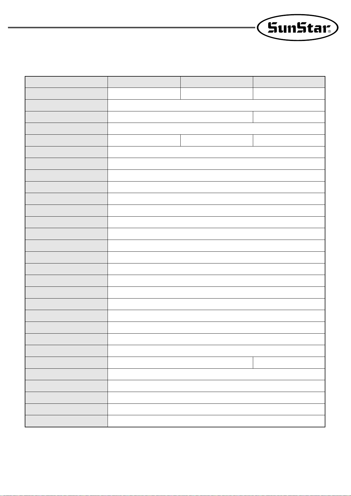
1.2) SPECIFICATIONS OF THE MACHINE
Series type
Usage
Sewing Area
Sewing Speed
Stitch Length
Needle
Needle Bar Stroke
Hook
Press Plate Lift
Adjusting the lowest position of the presser foot
Presser Foot Stroke
Lifting Amount of Presser Foot
Lifting Amount of Feeding Frame
Feeding System
Emergency Stop Function
Pattern Select Function
Memory
Memory Backup
Graphic OP
2nd Origin Function
Maximum Speed Limit
# of input stitches
Zoom-out/in ratio
Safety Device
Main Motor
Power Consumption
Recommended Temperature
Recommended Humidity
Power
Air Pressure
SPS/E-1507HS- SPS/E-1507GS- SPS/E-1507ES-
For heavy materials For general materials Extra heavy materials
150mm×70mm
Max. 2,700 spm (Stitich Length : 30mm or less)
Max. 2,000 spm (Stitich Length : 30mm or less)
0.05 ~ 12.7mm (Min. limit of resolution: 0.05mm)
DP×17 #18 DP×5 #14 DP×17 #23
41.2mm
Double capacity Shuttle Hook
Max. 25mm(Specifications : Max. 30mm)
Standard 0~3.5mm ( Max. 0~7mm)
Standard 4mm [0~7mm]
Max. 20mm
Max. 25mm
Full Closed Pulse Motor-based Feed
Available During Sewing Operation
Pattern No. Can be Selected from No.1 to No.999
USB Flash Drive
The Working Point is Stored in the Memory when the machine stops Abnormally
Options
Another Origin Point Can be Set by Using Jog Key
The Maximum Speed can be Limited from 200 to 2,700 spm
Max. 360,000 Stitches
1~400%(1% Step)
Emergency Stop Function, Maximum Speed Limit Function
Direct drive-type 550W AC servo motor
Direct drive-type 750W AC servo motor
600VA
5。C ~ 40。C
20% ~ 80%
1Ø : 100~240V, 3Ø: 200~440V, 50/60Hz
0.49Mpa(5kgf/㎠)
8
22
SAFETY RULES
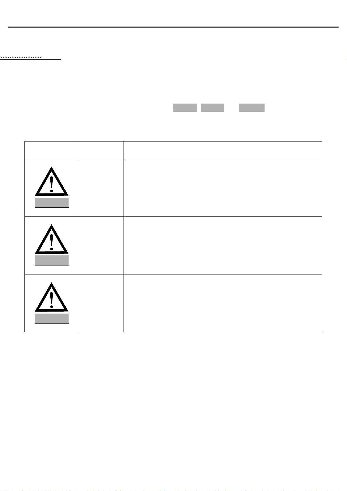
2.1) Safety Stickers
The safety stickers in this user’s manual are divided into , , and . They indicate that if
the safety rules are not kept, injury or damage to machine might occur as a result.
WarningDangerCaution
No. Name
Description
Caution
Warning
Danger
Caution
If the machine is not properly handled, it may cause injury to users or
physical damage to the machine.
If the machine is not properly handled, it may cause death or severe
injury to users.
If the machine is not properly handled, it may cause death or severe
injury to users, and the urgency of the danger is very high.
Warning
Danger
9
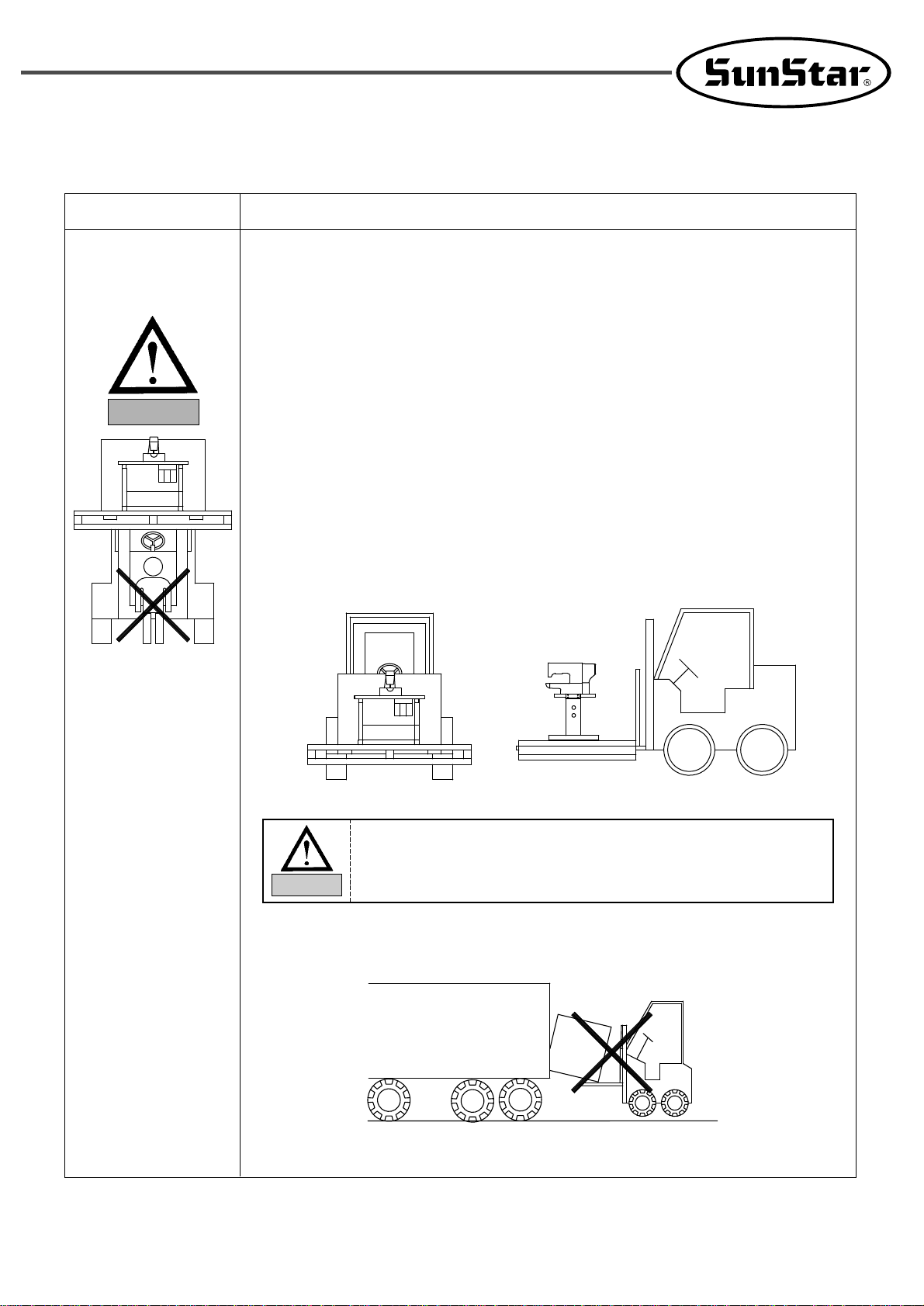
2.2) Machine Delivery
The machine delivery shall be conducted by the persons who are
knowledgeable about the safety instructions and rules. The following
safety rules must be observed:
2.2.1) Manual delivery
When the machine is delivered by persons, they shall wear special shoes and tightly
hold the machine on the left and right sides.
2.2.2) Forklift delivery
1) A forklift shall be big enough to endure the weight of the sewing machine and
carry the machine.
2) Use the palette when lifting the machine. Set the center of gravity of the machine
(center of the left and right sides) at the fork arm of the forklift and carefully lift
the machine.
Ban people from
standing under the
machine and remove
obstacles near the
machine.
Mark
Description
Danger
Make sure to maintain the balance of the machine when unloading the
machine by using a forklift or crane to prevent the deformation of the
machine or to prevent people from being exposed to danger.
Warning
10
Warning
2.3) Machine Installation
Caution
Depending on the installation environment, function errors, breakdown,
or other physical damage might result. Make sure to meet the following
conditions for machine installation:
1) The workbench or table where the machine is installed should be durable enough to
endure the weight of the machine (see the name plate).
2) Dust and humidity are the cause of machine pollution and erosion. Please install an air
conditioner and conduct regular maintenance of the machine.
3) Install the machine at the place where it is not exposed to direct sunlight (if the
machine is exposed to direct sunlight for a long time, it may cause discoloration or
deformation).
4) Secure the space around the machine. Place the machine at least 50cm away from the
left, right, and rear walls to secure sufficient space for maintenance activities.
5) Explosion risk : To prevent possible explosion, immediately stop the machine
operation if there are inflammable materials in the air.
6) Lighting : The machine does not offer lighting devices. When necessary, install needed
lighting.
7) Overturn risk : Do not install the machine on the unstable stand or table. If the machine
drops, it may cause injury or severe impact on the machine. If the machine is suddenly
stopped or the external impact is imposed, the machine might be capsized.
2.4) Machine Operation
The machine body is attached with and stickers at
each dangerous part to emphasize safety instructions. With the full
understanding of the safety instructions, make sure to observe the
following during machine operation:
1) Before turning on the power, read this manual thoroughly and have a full
understanding of machine operation.
2) Get properly dressed. Long hair, necklace, bracelet, or wide sleeve might be fed into the
machine during operation. W ear slip-free shoes to prevent slipping on the floor.
3) Check the moving scope of machine before its operation to find out whether the scope
is proper.
4) Keep hands and head away from the machine parts where accidents might occur
(needle, hook, thread take-up lever, pulley, etc.) during operation.
5) Do not remove the safety cover which protects pulley and shaft during machine
operation for user
’s safety.
6) Cut the power supply before disassembling the electric box such as the control box,
and double-check that the power switch is “Off.”
7) Make sure that the power switch is “Off”when the upper shaft is manually rotated.
8) Stop the machine when the needle is replaced or when inspecting the machine after
sewing work is done.
9) Make sure to follow the cautions below. Otherwise, physical damage to the machine
such as malfunction and breakdown might result:
- Do not put articles on the S/M table.
- Avoid using a crooked needle or the needle with damaged tip.
- Use the presser foot appropriate to working conditions.
WarningCaution
11
2.5) Repair and Maintenance
When machine repair is needed, it shall be conducted by SunStar A/S
engineers only who have finished the due training course.
1) For cleaning and repair, cut the main power supply. Wait for 4 minutes before starting
maintenance to make the machine completely discharged.
2) Do not modify the machine specifications or parts without substantial consultations with
SunStar. Otherwise, it may threaten safety during machine operation.
3) Use the parts manufactured by SunStar to repair or replace the machine parts during
A/S service.
4) When repairing is completed, re-install all the removed safety covers.
Danger
For main shaft motor and X,Y drive box, it takes 10 minutes before they
are completely discharged after the main power is cut.
Caution
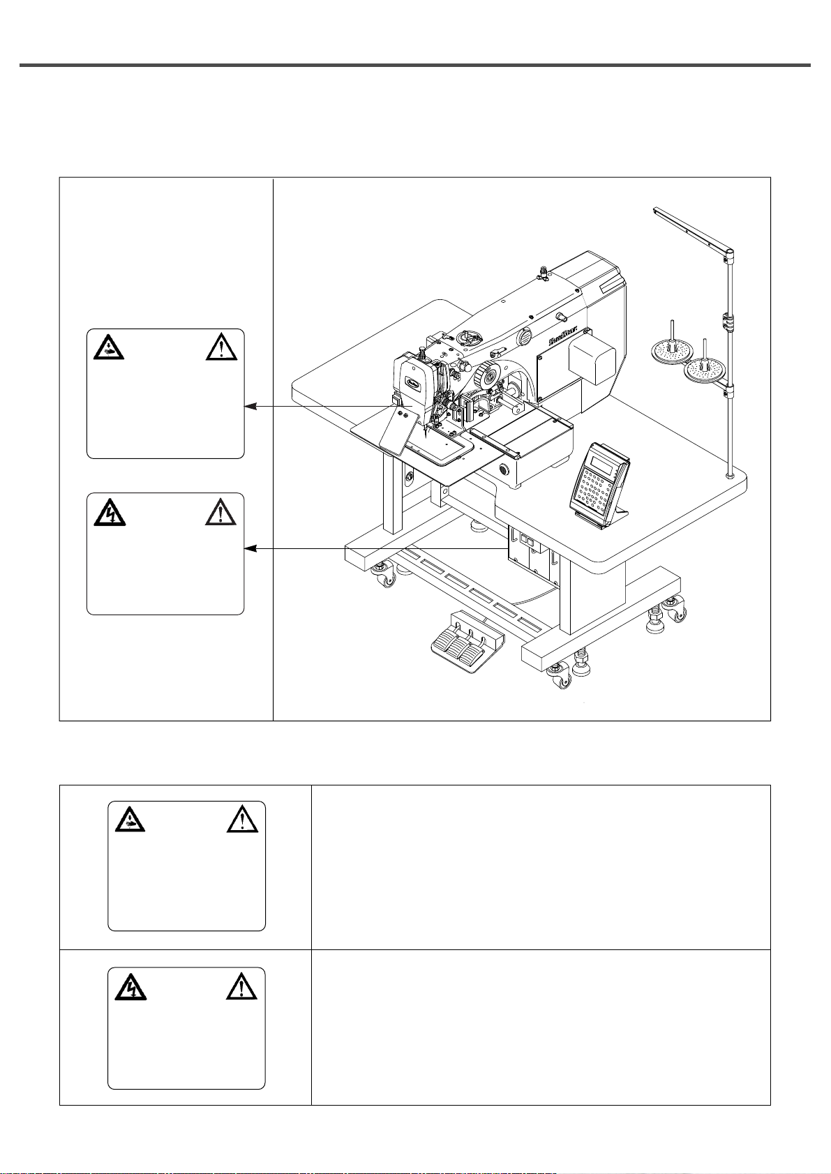
2.6) Devices for Safety
ⓐ Safety label : It describes cautions during operating the machine.
ⓑ Thread take-up lever : It prevents from any contact between body and take-up lever .
ⓒ Motor cover: Prevents any possible accidents while the motor is in motion.
ⓓ Step motor cover : It prevents from accidents during rotation of step motors.
ⓔ Label for specification of power : It describes cautions for safety to protect against
electric shock during rotating the motors.
ⓕ Safety plate : It protects eyes against needle breaks.
ⓖ Finger guard : It prevent from contacts between a finger and needle.
Caution
ⓒ
ⓑ
ⓐ
ⓐ
ⓔ
ⓕ
ⓖ
ⓓ
12
2.7) Location of Safety Labels
CAUTION
경고
Do not operate without finger guard and
safety devices. Before threading, changing
bobbin and needle, cleaning etc. switch off
main switch.
손가락 보호대와 안전장치 없이 작동하지
마십시오.
실, 보빈, 바늘교환시나 청소전에는 반드시
주전원의 스위치를 꺼 주십시오.
WARNING
경고
Hazardous voltage will cause injury.
Be sure to wait at least 360 seconds
before opening this cover after turn off
main switch and unplug a power cord.
고압 전류에 의해 감전될 수 있으므로 커버를
열 때는 전원을 내리고 전원 플러그를 뽑고 나
서 360초간 기다린 후 여십시오.
2.8) Type of Safety Labels
Do not operate without finger guard and safety devices. Before
threading, changing bobbin and needle, and cleaning, turn off the
main switch.
Hazardous voltage will cause injury .
Be sure to wait at least 360 seconds before opening this cover after
turn off main switch and unplug a power cord.
CAUTION
경고
Do not operate without finger guard and
safety devices. Before threading, changing
bobbin and needle, cleaning etc. switch
off main switch.
손가락 보호대와 안전장치 없이 작동하지
마십시오.
실, 보빈, 바늘교환시나 청소전에는 반드시
주전원의 스위치를 꺼 주십시오.
WARNING
경고
Hazardous voltage will cause injury.
Be sure to wait at least 360 seconds
before opening this cover after turn off
main switch and unplug a power cord.
고압 전류에 의해 감전될 수 있으므로 커버를
열 때는 전원을 내리고 전원 플러그를 뽑고 나
서 360초간 기다린 후 여십시오.
13
33
ASSEMBLY
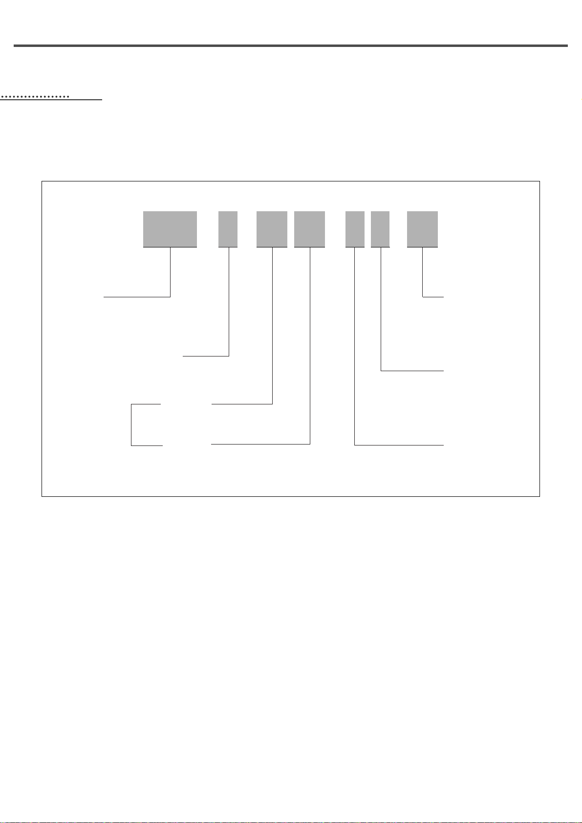
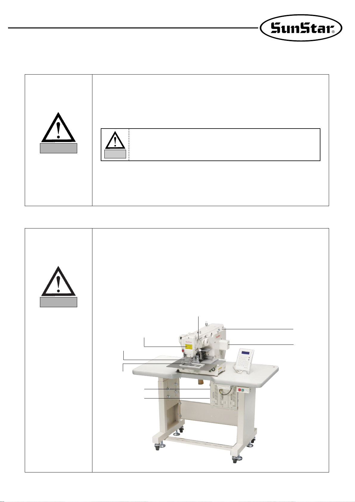
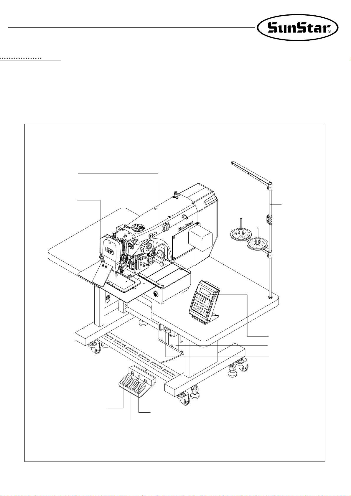
3.1) Name of Machine Parts
3.1.1) Name of Machine Parts
Arm
Emergency Switch
Sewing pedal
Manual pedal
Upper feed plate pedal
Power Switch
Control Box
OP Box
Thread Stand
14
44
Machine Installation
4.1) Installation Environment
1)
T o prevent accidents stemming from mal-operation, do not use the machine if the voltage is 10% above the rated voltage.
2) To prevent accidents stemming from mal-operation, make sure to check if the air pressure is proper before using
any air pressure devices such as air cylinder.
3) Proper temperature during machine operation : 0°~ 40°C (32°~ 104°F)
4) Proper temperature during machine storage : -25°~ 55°C (-13°~ 131°F)
5) Humidity : Relative humidity – within 45 ~ 85%
4.2) Electricity Environment
1) Power voltage
- The power voltage shall be within 10% of the rated voltage.
- It is recommended to use the power frequency within +/- 1% of the rated frequency (50/60Hz).
2) Noise of electromagnetic wave
- Do not share the power with the products which have either strong magnetic field or use high frequency. Make
the machine stay away from the products mentioned above.
3) Take care not to spill water and coffee on the machine.
4) Do not drop Control Box and the motor to the floor.
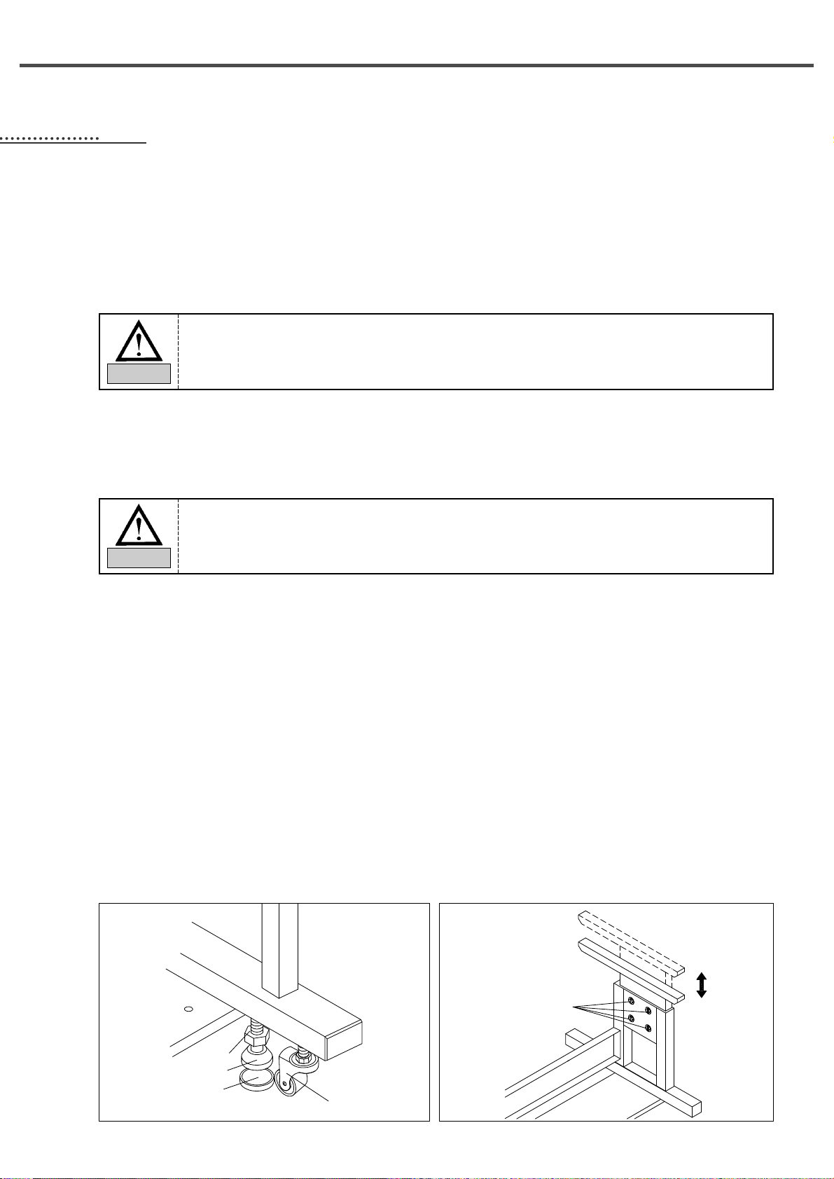
4.3) Table Installation
1) Table fixing
- Insert the shock absorbing rubber into the level adjuster and raise it until the caster freely moves.
- After the table is installed, tighten the nut to fix the level adjuster.
2) Table height adjustment
- Use the bolts attached to the table to adjust the height of the table to make sure that the users can smoothly and
conveniently work.
Nut
Level Adjuster
Shock Absorbing
Rubber
Caster
Bolt
To guarantee smooth operation of the product, the installation environment shall be prepared as
described in User’s Manual. Otherwise, unexpected damage might occur to the product.
Caution
The voltage shall be within 10% of the rated voltage.
Warning
15
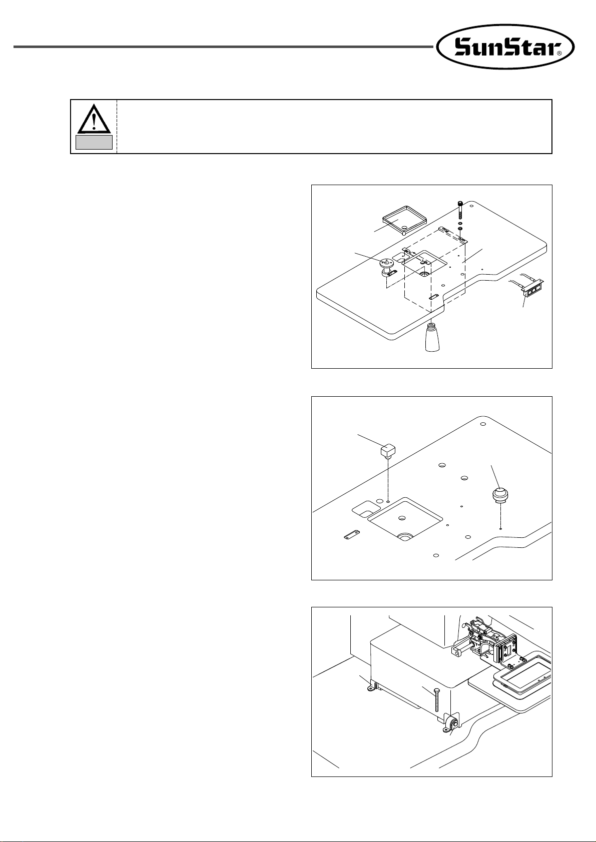
Hinge Rubber
4.4) Machine Installation
1) Install the waste oil can support, the oil dish, the
control box, and the power switch on the table.
2) Install the bed cushion rubber and the support
rubber for safety switch to prevent the machine
vibration and noises from occurring.
3) To fix the machine, attach the hinge and the hinge
rubber to the bed, and install them on the table by
using fixing bolts.
Fixing Bolt
To prevent safety accidents, at least two persons shall be assigned to machine installation or machine
delivery.
Caution
Cushion
Rubber
Safety Switch Rubber
Oil Dish
Waste Oil Can
Support
Control Box
Power Switch
Hinge
16
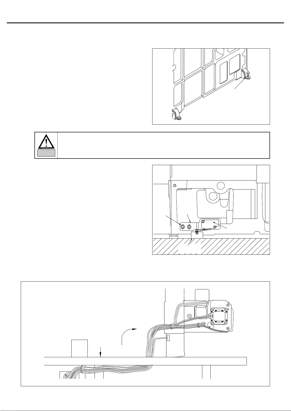
4) Since the machine has not been fully assembled,
take caution to lean the assembled machine on the
floor, and insert and fasten the bolt into the hinge
to completely fix the machine to the table.
Fixing Bolt
5) Install the safety switch and safety switch bracket on
the sewing machine, and then adjust the bracket
location of the safety switch to make sure that the
attached safety switch can properly operate.
To prevent safety accidents, at least two persons shall be assigned to machine installation or machine
delivery.
Caution
Safety Switch
Bracket
Safety Switch
Supporting Rubber
Tightening
Screw
Safety Switch
Table
6) Complete the cable connection between the machine and the control box, and fix the cables under the table as in
the figure (Set the length of the cables when fixing in consideration of the machine’s erection).
17
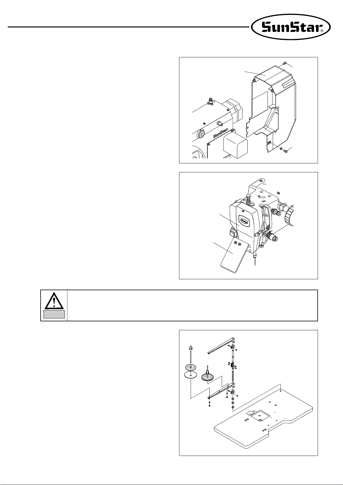
Fixing Screw
Fixing Screw
Motor Cover
4.5) Accessory Installation
4.5.1) Installation of Motor Cover
Attach the motor cover to the rear side of the
machine by using four fixing screws (4EA, small
size).
Safety Plate
Face Plate
4.5.2) Installation of Safety Plate
Attach the safety plate to the head.
4.5.3) Installation of Thread Stand
Assemble the thread stand and install it on the table.
Make adjustment to properly locate the thread stand.
To guarantee safety, make sure to install the safety plate before using the machine.
Caution
 Loading...