

SunStar SPS / D - B1254 H A - 20, SPS/D-B1254MA, SPS/D-B1254HA, SPS/D-B1254HA-BL, SPS/D-B1254MA-BL User Manual
...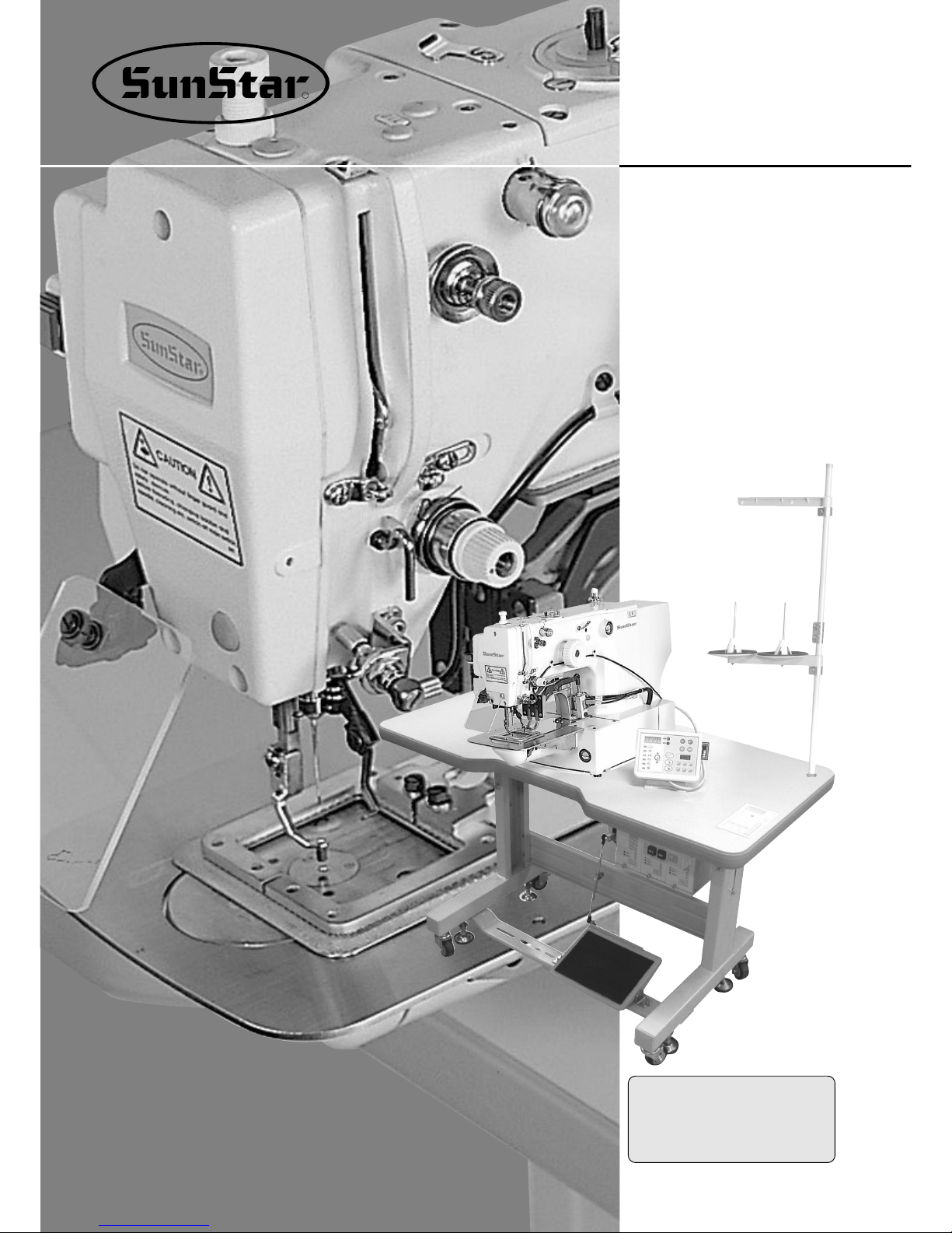
SSUUNNSSTTAARR MMAACCHHIINNEERRYY CCOO..,, LLTTDD..
DDiirreecctt DDrriivvee,, EElleeccttrroonniiccaallllyy
CCoonnttrroolllleedd DDeeccoorraattiivvee
PPaatttteerrnn TTaacckkiinngg MMaacchhiinnee
((MMeecchhaanniiccaall PPaarrtt))
USER’S
MANUAL
SPS/ D-B1254 Series
SPS/ D-B1263 Series
R
1) FOR AT MOST USE WITH EASINESS,
PLEASE CERTAINLY READ THIS MANUAL
BEFORE STARTING USE.
2) KEEP THIS MANUAL IN SAFE PLACE FOR
REFERENCE WHEN THE MACHINE BREAKS
DOWN.
MMMMEE--005511113300

Best Quality
Best Price
Best Service
SSUUNNSSTTAARR MMAACCHHIINNEERRYY CCOO..,, LLTTDD..
R
1.
Thank you for purchasing our product. Based on the rich expertise and
experience accumulated in industrial sewing machine production, SUNSTAR
will manufacture industrial sewing machines, which deliver more diverse
functions, high performance, powerful operation, enhanced durability, and
more sophisticated design to meet a number of user’s needs.
2. Please read this user’s manual thoroughly before using the machine. Make
sure to properly use the machine to enjoy its full performance.
3. The specifications of the machine are subject to change, aimed to enhance
product performance, without prior notice.
4.
This product is designed, manufactured, and sold as an industrial sewing
machine. It should not be used for other than industrial purpose.
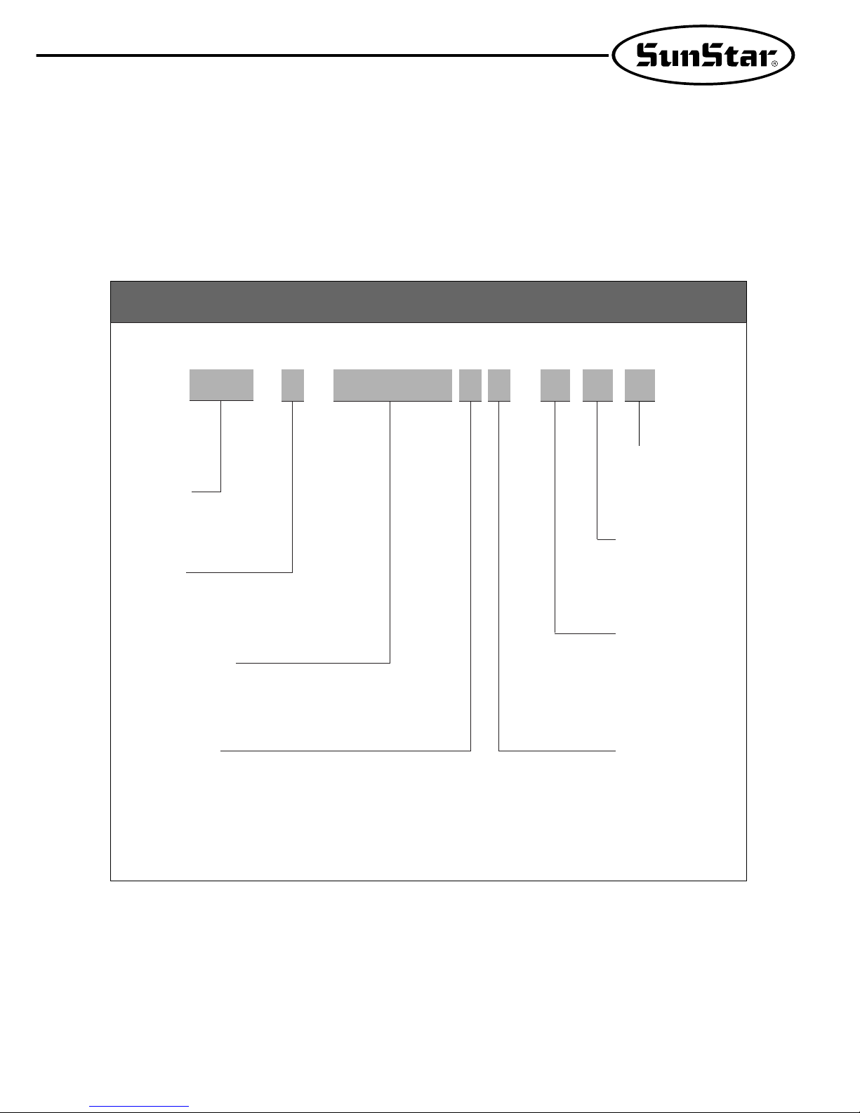
Organization of the Pattern Tacking S/M MODEL
SPS / D - B12
HA -
④ Material Type
H : Heavy Weight Material
M : Medium Weight Material
① SunStar
Pattern
System
② Series
D : Direct Drive Type
③ Pattern Tacking
Model Name
54 : 50×40mm
63 : 60×30mm
⑥ Feed Frame
Driven Type
20 : Mono Lithic Feed
Frame
22 Separately Driven
Feed Frame
⑦ Option
TH : Upper Thread
Holding Device
⑧ Hook Type
BL : Large Shuttle Hook
⑤ Pneumatic Type
(Standard)

4
Contents
1. Machine Safety Regulations 6
1) Machine Transportation 6
2) Machine Installation 6
3) Machine Repair 6
4) Machine Operation 7
5) Devices for Safety 7
6) Caution Mark Position 8
7) Contents of Marks 8
2. Machine Specifications 9
3. Machine Structure 10
1) Names of Each Part of the Machine 10
4. Machine Installation 11
1) Machine Installation Conditions 11
2) Electric Installation Conditions 11
3) How to Install the Table 11
4) The Assembly of Peripheral Parts 14
5) Installation Method of Air Pressure Specifications 15
5. Preparations Before Operating the Machine 18
1) How to Supply Oil 18
2) How to Install the Needle Bar 19
3) How to Thread the Upper Thread 20
4) Threading the Lower Thread 20
5) How to Take the Bobbin Case On and Off 20
6) How to Adjust the Tension of the Upper Thread and the Lower Thread 21
7) How to Wind the Lower Thread 21
8) How to Operate a Pedal (A-20 Type) 22
9) How to Operate a Pedal (A-22 Type) 22
10) Disposing the Waste Oil 22
11) Compressed Air Input and Air Pressure Adjusting Method 23
12) Adjusting Method of Upper Thread Holding Device (Option) 23

5
6. How to Repair the Machine 24
1) Adjusting the Height of the Needle Bar 24
2) Adjusting the Needle and the Shuttle 24
3) Adjusting the Lower Shaft Gear and the Rocking Shaft Gear 25
4) Adjusting the Position of Shuttle Upper Spring 25
5) Adjusting the Height of the Feed Plate 26
6) Adjusting the Height of the Presser Foot Devices 26
7) Adjusting the Presser Foot Devices 26
8) Adjusting the Parts for Thread Release 28
9) Adjusting the Wiper Parts 30
10) Adjusting the Parts for Trimming 31
11) Adjusting the Devices for Main Thread Adjustment 33
12) Adjusting the Winder Devices 33
13) Adjusting the Hand Pulley Device 34
14) Mounting the Direct Motor and Adjusting Method 34
15) Setting Up the X-Y Origin 35
7. Cause of Breakdown and Troubleshooting 36
1) Machine Part 36
8. Pattern List 37
9. Drawing of Table 39
10. Gauge List 40
11. Pneumatic Diagram 43
1) Drawing of the Pneumatic Hose of SPS/D-B1254A-20, SPS/D-B1263A-20 Machine
(for Monolithic Feed Frame)
43
2) Drawing of the Pneumatic Hose of SPS/D-B1254A-22, SPS/D-B1263A-22 Machine
(for Separately Driven Feed Frame)
44
6
11
MACHINE SAFETY REGULATIONS
Safety instruction on this manual are defined as Danger, Warning and Notice.
If you do not keep the instructoins, physical injury on the human body and machine damage might be occurred.
1-1) Machine Transportation
Danger
1-2) Machine Installation
Notice
1-3) Machine Repair
Danger
Those in charge of transporting the machine should know the safety regulations very
well. The following indications should be followed when the machine is being
transported.
ⓐ More than 2 people must transport the machine.
ⓑ To prevent accidents from occurring during transportion, wipe off the oil on the
machine well.
The machine may not work well or breakdown if installed in certain places, install the
machine where the following qualifications agree.
ⓐ Remove the package and wrappings starting from the top. Take special notice on the
mails on the wooden boxes.
ⓑ Dust and moisture stains and rusts the machine. Install an airconditioner and clean
the machine regularly.
ⓒ Keep the machine out of the sun.
ⓓ Leave sufficient space of more than 50㎝ behind, and on the rigth and left side of the
machine for repairing.
ⓔ EXPLOSION HAZARDS
Do not operate in explosive atmospheres. To avoid explosion, do not operate this
machine in an explosive atomsphere including a place where large quantities of
aerosol spray product are being used or where oxygen is being administered unless it
has been specifically certified for such operation.
ⓕ The machine were not provided with alocal lighting due to the feature of machine.
Therefore the illumination of the working area must be fulfilled by end user.
[Refer]Details for machine installment are described in 4. Machine Installment.
When the machine needs to be repaired, only the assigned troubleshooting engineer
educated at the company should take charge.
ⓐ Before cleaning or repairing the machine, close down the motive power and wait 4
minutes till the machine is completely out of power.
ⓑ Not any of the machine specifications or parts should be changed without consulting
the company.
Such changes may make the operation dangerous.
ⓒ Spare parts producted by the company should only be used for replacements.
ⓓ Put all the safety covers back on after the machine has been repaired.
Danger :
This indication should be observed definitely. If not, danger could be happen during the installation, conveyance
and maintenance of machines.
Warning :
When you keep this indication, injury from the machine can be prevented.
Notice :
When you keep this indication, error on the machine can be prevented.
7
ⓐ
ⓒ
ⓓ
ⓕ
ⓔ
ⓑ
SPS/D-B1254(B1263) Series is made to sew patterns on fabrics and other similar material for
manufacturing. Follow the following indications when operating the machine.
ⓐ Read through this manual carefully and completely before operating the machine.
ⓑ Wear the proper clothes for work.
ⓒ Keep hands or other parts of the body away from the machine operation parts(needle, shuttle,
thread take-up lever, and pulley etc.) when the machine is being operated.
ⓓ Keep the covers and safety plates on the machine during operation.
ⓔ Be sure to connect the earthing conductor.
ⓕ Close down the electric motive power and check if the switch is turned “off ”before opening
electric boxes such as the control box.
ⓖ Stop the machine before threading the needle or checking after work.
ⓗ Do not step on the pedal when turning the power on.
ⓘ Do not operate the machine with any cooling fan blocked.
The air-filter on control box must be cleaned once a week.
ⓙ If possible, install the machine away from source of strong electrical noise such as high
frequency welding machines
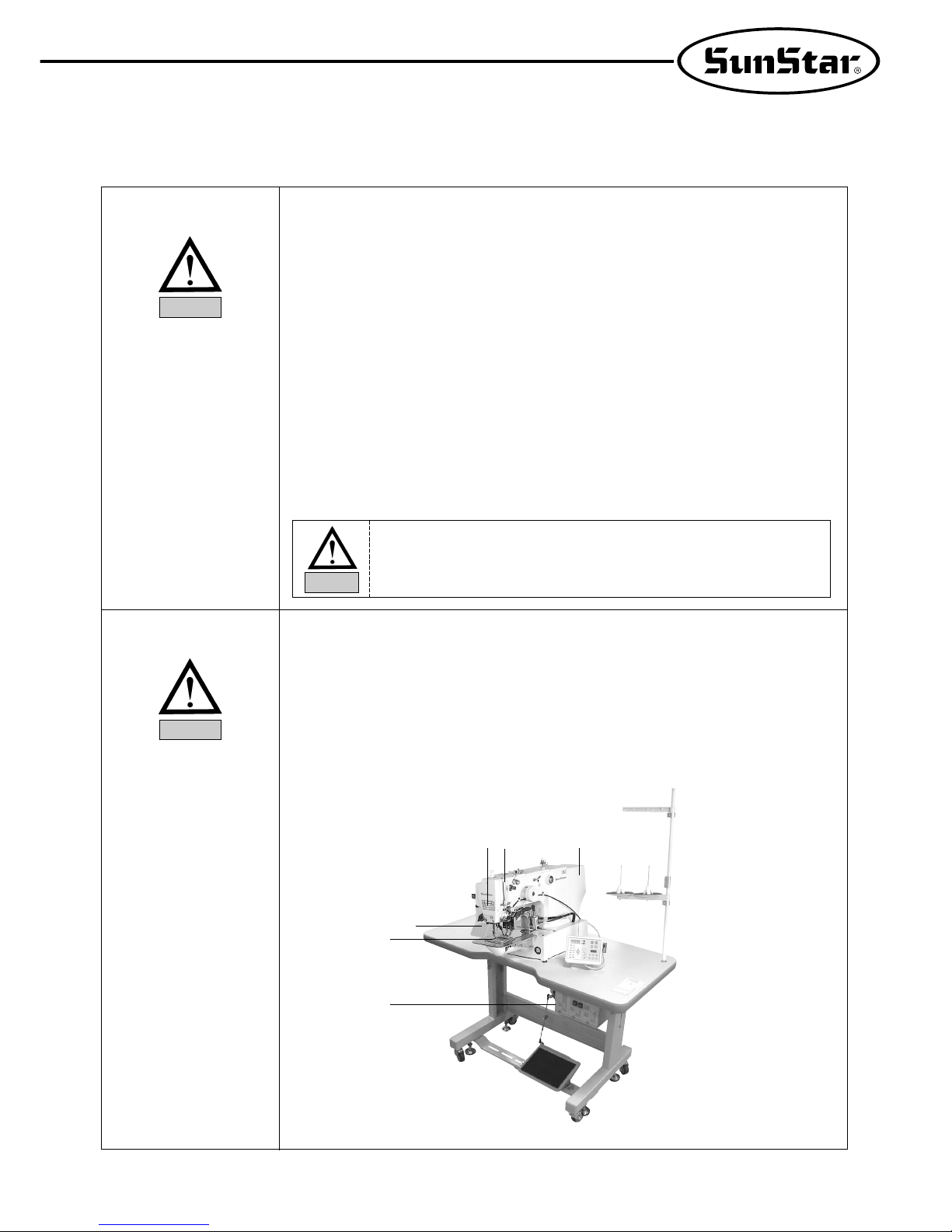
1-4) Machine Operation
Warning
ⓐ Safety label : It describes cautions during operating the machine.
ⓑ Thread take-up cover : It prevents from any contact between body and take-up lever.
ⓒ Motor cover : It prevents from insertion of hands.feet or clothes by motor.
ⓓ Label for specification of power : It describes caution for safety to protect against electric shock
during rotation the motors.
ⓔ Finger guard : It prevent from contacts between a finger and needle.
ⓕ Safety plate : It protect eyes against needle breaks.
1-5)
Devices for safety
Warning
Belt will crush or amputate finger or hand, keep cover in place before
operating, turn off power before inspecting or adjusting.
Warning
8
Caution mark is attached on the machine for safety.
When you operate the machine, obesrve the directions on the mark.
Position of Warning Mark
[View from the right-front]
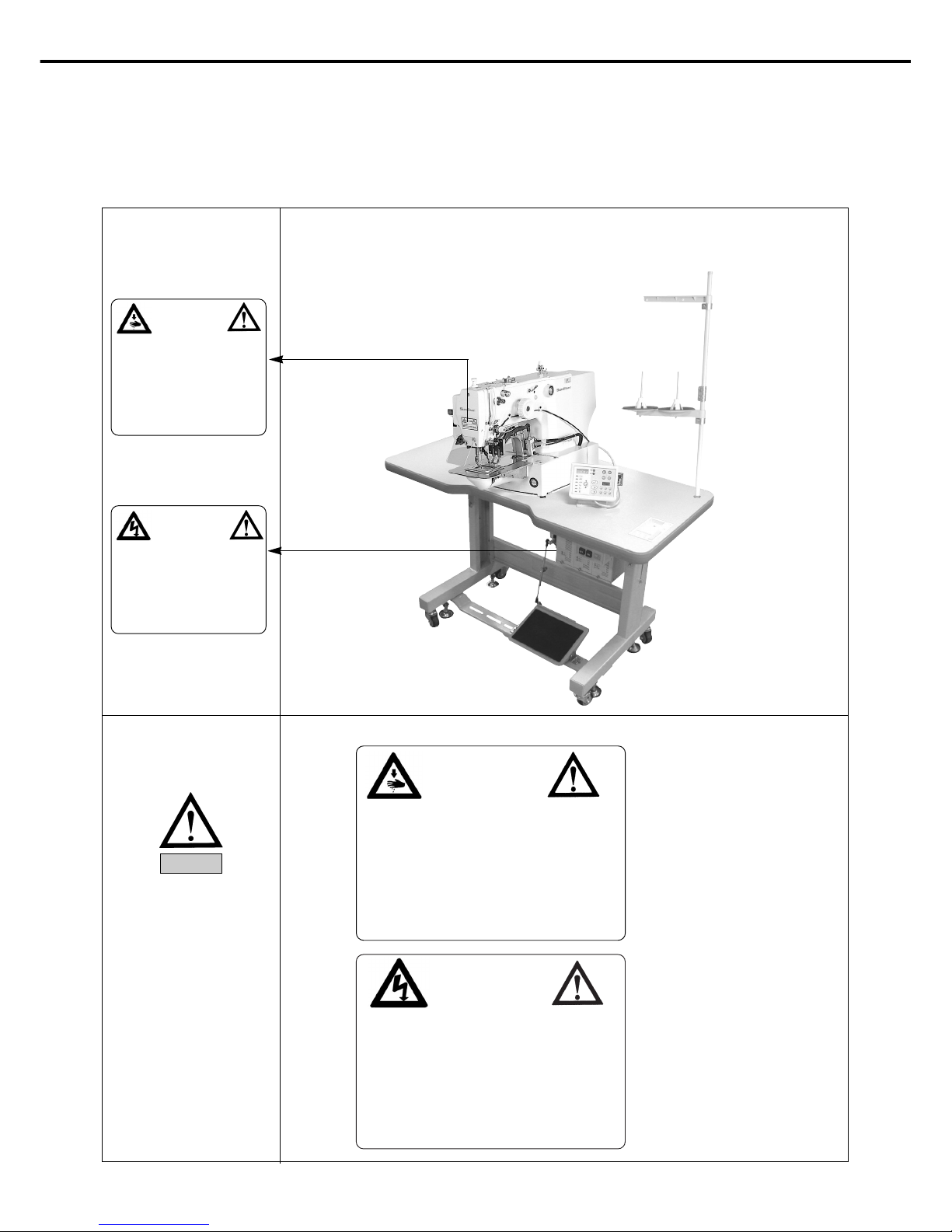
1-6) Caution Mark Position
Caution
1)
2)
1-7) Contents of Marks
Warning
CAUTION
주의
Do not operate without finger guard and
safety devices. Before threading, changing
bobbin and needle, cleaning etc. switch off
main switch.
손가락 보호대와 안전장치 없이 작동하지
마십시오.
실, 보빈, 바늘교환시나 청소전에는 반드시 주
전원의 스위치를 꺼 주십시오.
WARNING
경고
Hazardous voltage will cause injury.
Be sure to wait at least 360 seconds before
opening this cover after turn off main switch
and unplug a power cord.
고압 전류에 의해 감전될 수 있으므로 커버를
열 때는 전원을 내리고 전원 플러그를 뽑고 나
서 360초간 기다린 후 여십시오.
CAUTION
주의
Do not operate without finger guard
and safety devices. Before threading,
changing bobbin and needle, cleaning
etc. switch off main switch.
손가락 보호대와 안전장치 없이 작동하지 마
십시오.
실, 보빈, 바늘교환시나 청소전에는 반드시
주전원의 스위치를 꺼 주십시오.
WARNING
경고
Hazardous voltage will cause injury.
Be sure to wait at least 360 seconds
before opening this cover after turn
off main switch and unplug a power
cord.
고압 전류에 의해 감전될 수 있으므로 커버
를 열 때는 전원을 내리고 전원 플러그를 뽑
고 나서 360초간 기다린 후 여십시오.
9
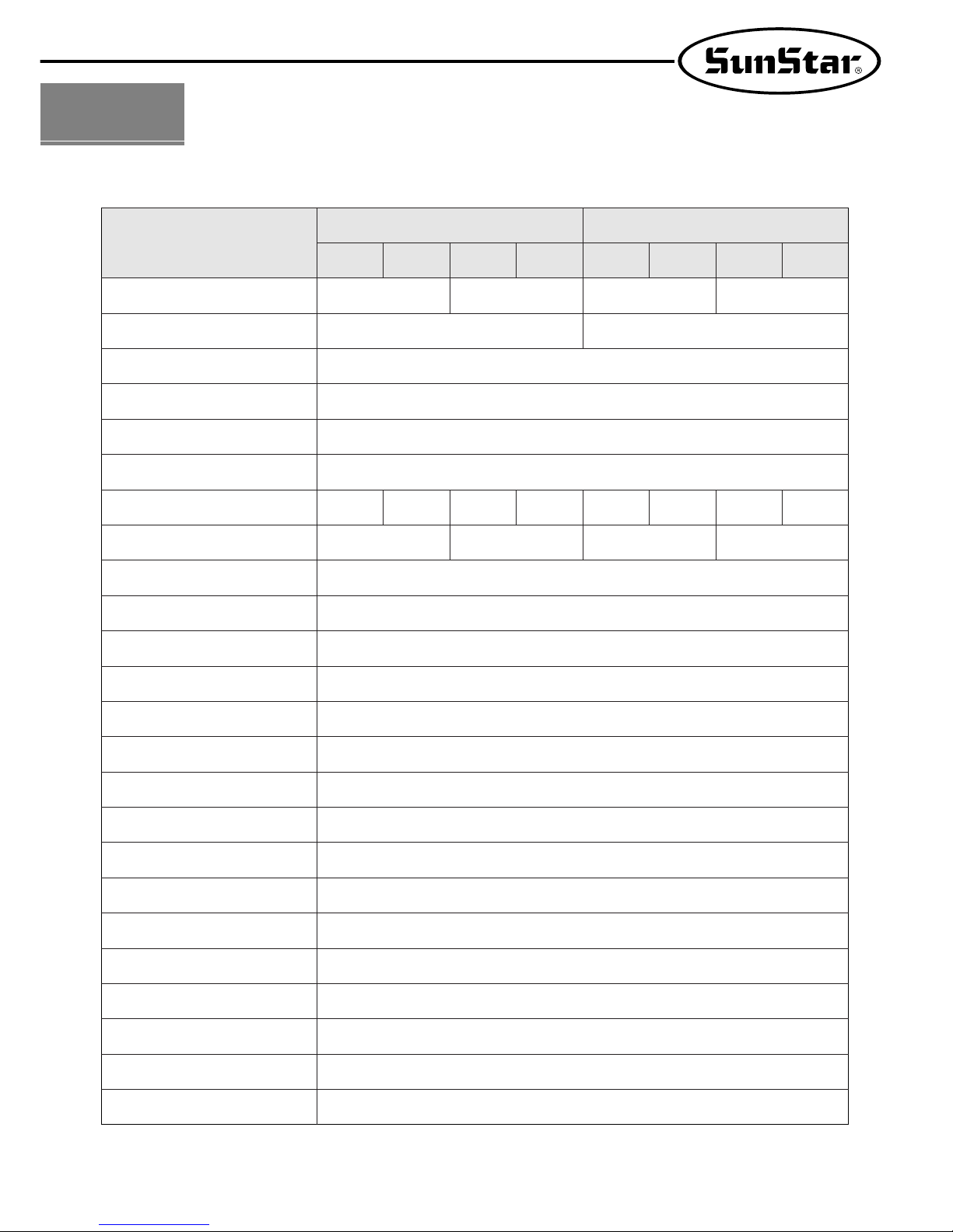
22
MACHINE SPECIFICATIONS
MODEL
HA
SPS/D-B1254
SPS/D-B1263
HA-BL MA MA-BL HA HA-BL MA MA-BL
50mm×40mm 60mm×30mm
Application
Sewing Area(X, Y)
Sewing Speed
Stitch Length
Feeding System
Stroke
Hook
Needle
Lifting Amount of Feeding Frame
Lifting Amount of Presser Foot
Thread Trimmer
Emergency Stop Switch
Wiper
No. of Stitches
Standard No. of Patterns
Number of Patterns
Memory
Enlarging/Reducing
Motor
Power Consumption
Recommended Temperature
Recommended Humidity
Power
Ariborne Noise Humidity
Max. 2,500spm (Stitch Length is 3mm or Less)
0.1∼10mm
Feeding by Pulse Motor
41.2mm
Max. 20mm
Max. 20mm
Standard
Standard
Standard (Electronically Solenoid Type)
Max. 10,000 Stitches
56 Patterns (Pattern : 24, Bartack : 32)
Max. 99 Pattems (Standard 56 Patterns)
EP-ROM
20%∼ 200% (1% Step)
Direct Drive AC Sero Motor
600VA
5°C∼40°C
20%∼ 80%
1-Phase: 100V∼240V, 3-Phases 200V∼440V, 50/60㎐
0.49MPa (5kgf/cm²)
For Heavy Weight
Materials
For Medium Weight
Materials
For Heavy Weight
Materials
For Medium Weight
Materials
DP×17 #19
(#19∼#23)
DP×5 #16
DP×17 #19
(#19∼#23)
DP×5 #16
Standard
Shuttle Hook
Large shuttle
hook
Standard
Shuttle Hook
Large shuttle
hook
Standard
Shuttle Hook
Large shuttle
hook
Standard
Shuttle Hook
Large shuttle
hook
10
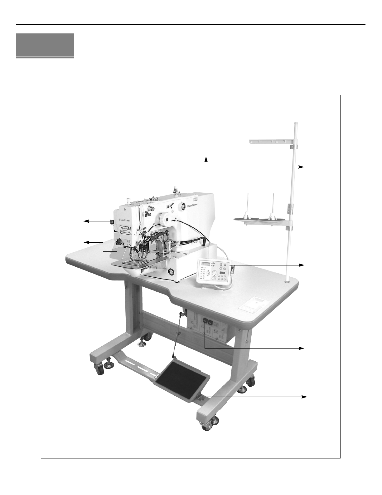
33
MACHINE STRUCTURE
1) Names of Each Part of the Machine
Thread Stand
Operation Box
Motor Cover
Power Switch
Pedal Switch
Arm
Emergency
Stop Switch
Safety Plate
Ass’y
11
44
MACHINE INSTALLATION
1) Machine Installation Conditions
A. Do not use the machine where the voltage is over regular voltage ±10% to prevent accidents
B. For safe operation of the machine, use the machine under the following conditions.
Surrounding Temperatuer During Operation : 5。~40℃ (41。F~104。F)
Surrounding Temperature During Maintenance : -10。~60℃(14。F~140。F)
C. Humidity : Between 20~80%(Relative humidity)
2) Electric Installation Conditions
A. Power Voltage
· The power voltage must be between regular voltage ±10%
· The frequency of the power should be regular frequency(50/60㎐) ±1%
B. Electromagnetic Wave Noise
Use separate power with strong magnetics of high frequency products, and do not leave the machine near them.
C. Ues low voltage when supplements or accessories are being adhered.
D. Be careful not to have water of coffee be spilled into the Controller and Motor.
E. Do not drop the Controller or Motor.
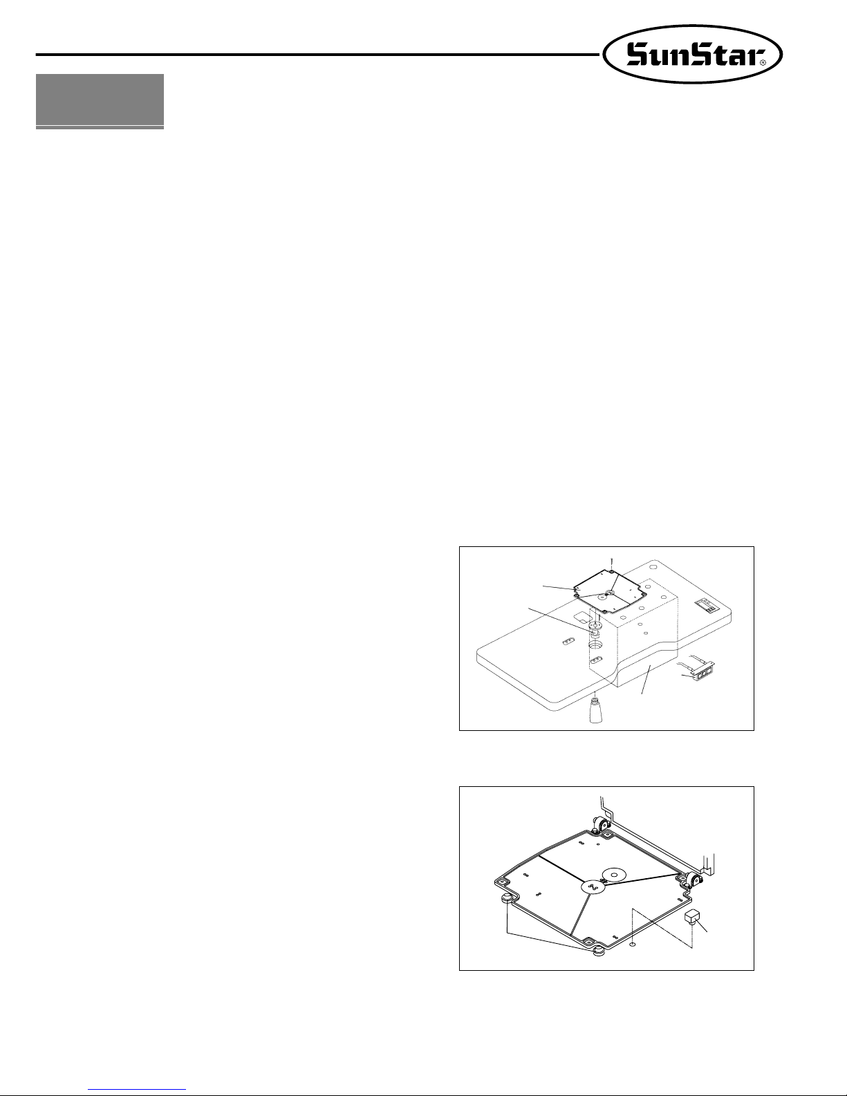
[ Fig. 1 ]
A. Please fix the oil tub support ①, the oil support ②, the
control box ③ and the power switch ④ on the table.
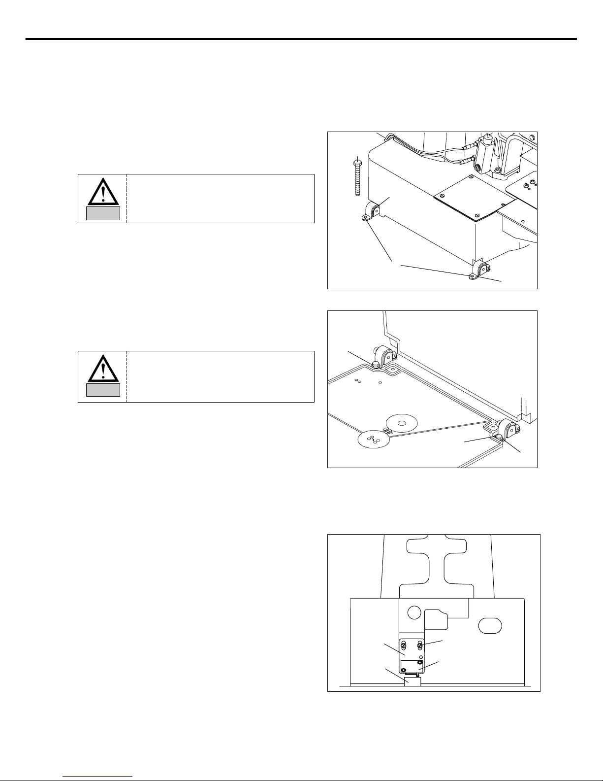
3) How to Install the Table
[ Fig. 2 ]
B. Attach the bed cushion rubber ① and safety switch
supporting rubber ② to the table.
①
①
②
②
③
④
12
C. Add the hinge metal and hinge rubber to the bed.
Then insert the fixing bolt into the hinge metal hole of
point ① and fix the table as shown in the picture.
D. Stand the machine as shown in the picture, and then fix
the machine on the table after inserting the fixing bolts
into the hinge metal holes of point ①.
[ Fig. 3 ]
[ Fig. 4 ]
Hinge Rubber
Bolt
①
Hinge
①
①
Bolt
E. Assemble the safety switch bracket ① on the bed as in
the figure. Move the safety switch bracket up and down to
make sure that the safety switch supporting rubber ② is
tightly pressed by the safety switch ③, and then fasten the
screw ④.
[ Fig. 5 ]
②
④
③
①
The machine should be carried by more
2 people for safety
Danger
Since the machine is not perfectly installed
on the table, extreme care is needed
when you make the machine stand up not
to have any accident occurred.
Danger
13
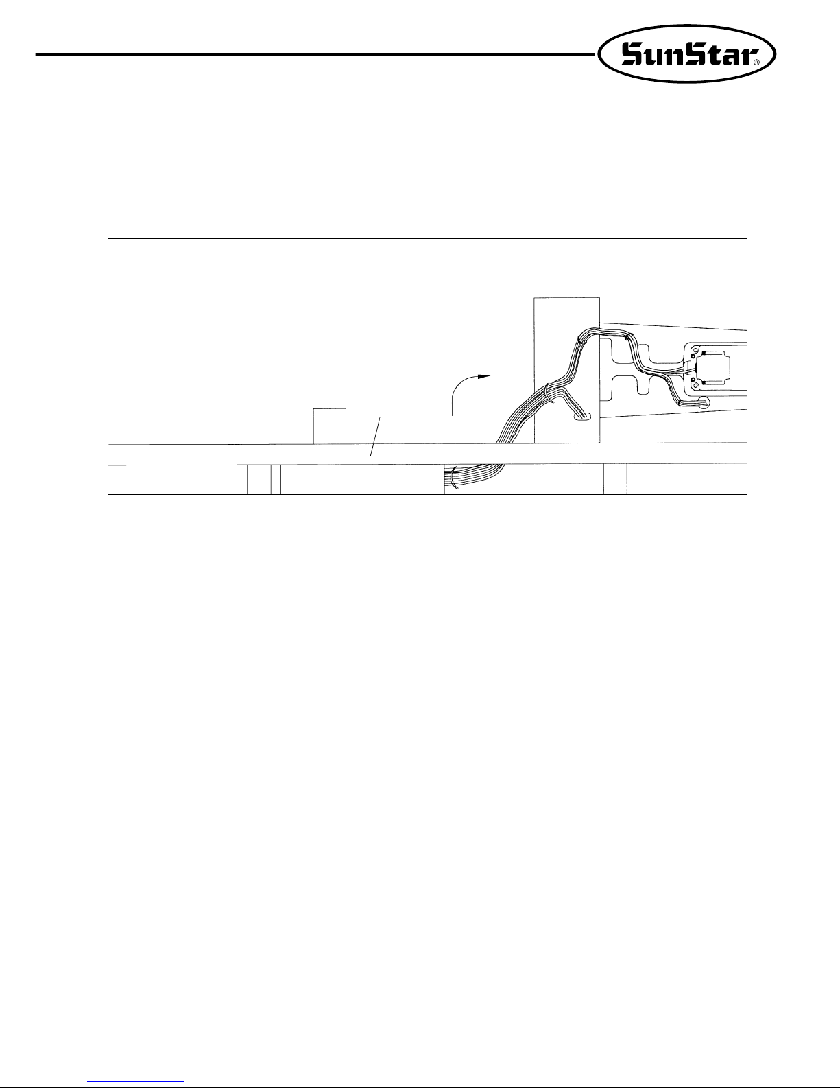
[ Fig. 6 ]
F. After the cable connections beween the machine and the control box is finished, fix the cable wiring under the table
as shown in the picture.
(Adjust the length of the wire considering the situation of standing the machine.)
Table
14
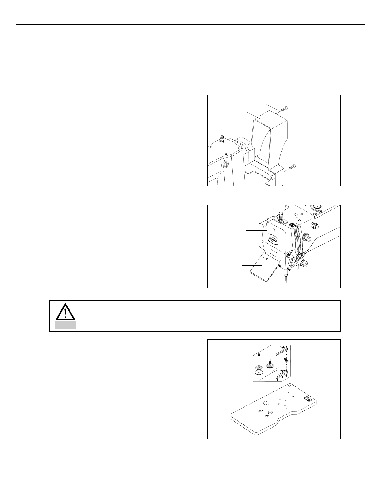
C. Install the thread stand on the table.
[ Fig. 9 ]
[ Fig. 7 ]
A. Attach the motor cover on the back side of the machine
(4 positions) by using the 4 joint screws.
4) The Assembly of Peripheral Parts
[ Fig. 8 ]
B. Attach the safety plate to the left side of machine by using
fixing bolt.
Motor Cover
Fixing Screw
Face Plate
Safety Plate
Ass’y
For safety, motor cover and safety plate should be attached to the machine.
Caution
 Loading...