


1) FOR AT MOST USE WITH EASINESS,
PLEASE CERTAINLY READ THIS MANUAL
BEFORE STARTING USE.
2) KEEP THIS MANUAL IN SAFE PLACE
FOR REFERENCE WHEN THE MACHINE
BREAKS DOWN.
MMEEEE--110011002200
USER
’’
S MANUAL
R
SSuunnSSttaarr CCOO..,, LLTTDD..
SPS/A-Pattern Series
SPS/B-Pattern Series
SPS/C-Pattern Series
Electronically Controlled
Pattern Sewing Machine
(Electronic Control Part)

Best Quality
Best Price
Best Service
SSUUNNSSTTAARR CCOO..,, LLTTDD..
R
1.
Thank you for purchasing our product. Based on the rich expertise and
experience accumulated in industrial sewing machine production, SUNSTAR
will manufacture industrial sewing machines, which deliver more diverse
functions, high performance, powerful operation, enhanced durability, and
more sophisticated design to meet a number of user’s needs.
2. Please read this user’s manual thoroughly before using the machine. Make
sure to properly use the machine to enjoy its full performance.
3. The specifications of the machine are subject to change, aimed to enhance
product performance, without prior notice.
4.
This product is designed, manufactured, and sold as an industrial sewing
machine. It should not be used for other than industrial purpose.
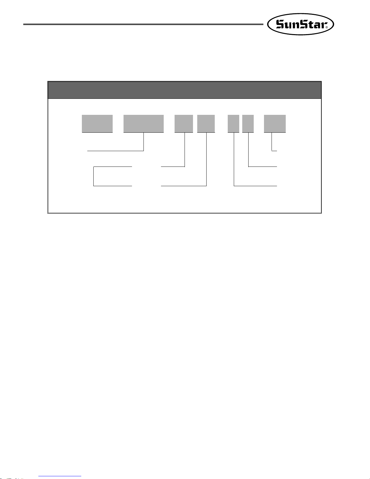
Pattern Type
A : Belt Type
B : Direct Type
C :
Separated upper and lower operation type
Sewing Type
1306 : X(130mm), Y(60mm)
1310 : X(130mm), Y(100mm)
1507 : X(150mm), Y(70mm)
1811 : X(180mm), Y(110mm)
2211 : X(220mm), Y(110mm)
2516 : X(250mm), Y(160mm)
3020 : X(300mm), Y(200mm)
5030 : X(500mm), Y(300mm)
5050 : X(500mm), Y(500mm)
8050 : X(800mm), Y(500mm)
Material Type
G:General Material
H:Heavy Material
Stitch
S:Standard Stitch
P:Perfect Stich
Feed Frame
10:Electronic
20:Pneumatic Monolithic Feeding Frame
22:Pneumatic Separately-Driven Feeding
23:Pneumatic Reverse Device
Attach/Separate Feed Frame
SPS/C-Series
01:Arm Lifting Type
02:Fixed Arm Type
Organization of the Pattern S/M Model
Series
Sewing Area
SPS / A,B,C - 13 0 6 - H S-10
(X)×10mm
(Y)×10mm
Feeding Frame
Type
Stitch Type
Material Type

1. Machine Safety Regulations …………………………………………………………… 6
2. I/O Board Dip Switch Setting ………………………………………………………… 9
3. Basic Operational Method ……………………………………………………………… 10
1) Name and roles of each key on operation unit……………………………………………… 10
2) Name and description of each display contents on general operation mode …………… 11
3) Flow chart of general operation ……………………………………………………………… 12
4) Work flow of pattern programming …………………………………………………………… 13
5) Operating after reading the patterns from USB flash drive ……………………………… 14
6) Confirming the working pattern read from the USB flash drive ………………………… 14
7) When a machine stops operating during sewing by the thread cut ……………………… 15
8) Emergency stop during operation ……………………………………………………………… 15
9) Winding the thread …………………………………………………………………………… 15
10) Safety Functions ………………………………………………………………………………… 16
4. Applicable Operation ……………………………………………………………………… 19
1) Pattern Data Generation Function………………………………………………………………………… 19
1-1) Program example 1 : Generating the square pattern ………………………………… 19
1-2) Program example 2 : Generating the circle pattern ………………………………… 21
1-3) Program example 3 : Generating the double curve pattern ………………………… 23
1-4) Program example 4 :
Pattern generation by using the second origin and pause
…… 26
1-5) Zigzag shape selecting function to generate zigzag …………………………………… 30
2) Pattern Data Edit Function …………………………………………………………………… 32
2-1) One stitch movement function …………………………………………………………… 32
2-2) Partial movement function of pattern data …………………………………………… 33
2-3) A fix number of stitch delete function ………………………………………………… 35
2-4) Partial pattern data delete function …………………………………………………… 36
2-5) Partial stitch width changing function ………………………………………………… 38
2-6) Pattern partial copy function …………………………………………………………… 39
2-7) Pattern data inserting function…………………………………………………………… 41
3) Pattern Data Application Function …………………………………………………………… 43
3-1) Operation after reading pattern data from USB flash drive and moving the second
temporary start point ……………………………………………………………………… 43
3-2) Program example 5 : Change of sewing speed within a pattern …………………… 44
3-2-1) Changing the sewing speed from an existing pattern data ………………… 44
3-2-2) Changing the sewing speed by making new pattern data…………………… 47
3-3) Program example 6 : Use of reversal ………………………………………………… 49
3-3-1) Pattern programming by using reversal………………………………………… 49
3-3-2) Adding the code to already programmed pattern …………………………… 52
3-4) Using the extension/reduction modes …………………………………………………… 54
3-5) Using the chain sewing mode …………………………………………………………… 56
3-6) Change/saving function of pattern data start point ………………………………… 58
3-7) Change/saving function of pattern 2nd original point ………………………………… 60
3-8)
Change/saving function of maximum pattern sewing speed and extension/reduction rate
…… 61
3-9) Symmetrical shape creating function of pattern ……………………………………… 63
3-10) Condensed sewing stitch inserting function …………………………………………… 64
3-11) Automatic Back Tack(B/T) inserting function ………………………………………66
3-12) OverLap sewing stitch inserting function ………………………………………………67
3-13) Automatic insertion of thread trimmer code when deleting stitches ……………… 69
3-14) Setting-up reference point for zooming ………………………………………………… 70
3-15) Embroidery design call function ………………………………………………………… 72
3-16) JUKI Design Call ………………………………………………………………………… 73
3-17) Sewing limit function …………………………………………………………………… 74
3-18) Quick origin search motion function for 1811 machines …………………………… 76
3-19) Setting origin search function of upper and lower shafts after finishing sewing
[only applied for SPS/C-Series]………………………………………………………… 77
3-20) Setting machine Head up or down function [Only for SPS/C-
Series
] …………… 78
3-21)
Setting reverse rotation after trimming [Only applied for SPS/
B/
C-Series]
………… 79
CONTENT

3-22)
Setting the angle of reverse rotation after trimming [
O
nly applied for SPS/B/C-Series]
…80
3-23) Setting output port [Only applied for SPS/C-Series] ……………………………… 81
3-24)
Setting time delay when output port is being used [
O
nly applied for SPS/C-Series]
…84
3-25) 3rd Thread Adjusting Device (TR3) Setting ………………………………………… 85
3-26) Basic Clamp Position Setting …………………………………………………………… 88
4) Pattern Data General Function ……………………………………………………………… 89
4-1) Checking and deleting the pattern number …………………………………………… 89
4-2) Making a copy the pattern to another number or diskette ………………………… 90
4-3) Function to copy saved patternS from interior memory to USB flash drive …… 91
4-4) Pattern information displaying function ………………………………………………… 92
4-5) Change of parameter related to general sewing ……………………………………… 93
4-6) Initialization of parameter related to general sewing ………………………………… 94
4-7) System program update …………………………………………………………………… 95
4-8) Confirmation for version of system program ……………………………………………96
4-9) Bobbin counter setting by design………………………………………………………… 97
4-10) Saving in the Internal Memory after Creating Pattern Designs…………………… 99
5. High Operating Method …………………………………………………………………100
1) Understanding the function of machine test ………………………………………………… 100
1-1) Encoder test …………………………………………………………………………………100
1-2) Step motor-main shaft motor test (X-Y Main Test) ……………………………… 100
1-3) Main motor test …………………………………………………………………………… 101
1-4) Interrupt test ……………………………………………………………………………… 102
1-5) PWM test…………………………………………………………………………………… 102
1-6) LCD test …………………………………………………………………………………… 103
1-7) Keyboard test ……………………………………………………………………………… 104
1-8) Input 0 test ………………………………………………………………………………… 104
1-9) Input 1 test ………………………………………………………………………………… 105
1-10) Input 2 Test ……………………………………………………………………………… 106
1-11) Input 3 Test ……………………………………………………………………………… 106
1-12) Input 4 Test [Only applied for SPS/C-Series] ……………………………………… 107
1-13) Input 5 Test [Only applied for SPS/C-Series] ……………………………………… 107
1-14) Input 6 Test [Only applied for SPS/C-Series] ……………………………………… 108
1-15)
Lower Shaft Encoder Test (Encoder1 Test) [Only applied for SPS/C-Series]
………… 109
1-16) Solenoid Test ……………………………………………………………………………… 109
1-17) Output 4 Test [Only applied for SPS/C-Series] ……………………………………110
1-18) Output 5 Test [Only applied for SPS/C-Series] ……………………………………111
1-19) Other output ports[only applied for SPS/C-Series] ………………………………… 111
1-20) Manual operation test of step motor (XY Jog Test) ……………………………… 112
1-21) Origin Test ………………………………………………………………………………… 112
1-22) Jump Test ………………………………………………………………………………… 113
1-23)
Communication test between the main shaft board and the CPU/IO board (Async Test)
…… 113
6. Description on Parameter Related to General Sewing Operation ………………115
1) Function no. related pattern programming …………………………………………………… 164
2) Pattern chart……………………………………………………………………………………… 166
3) Parameter number related to general sewing ………………………………………………… 167
4) Error list …………………………………………………………………………………………172
5) SPS/A/B/C-Series block diagram……………………………………………………………… 174
6) Table drawing …………………………………………………………………………………… 178
7) Basic Manual …………………………………………………………………………………… 179
7. Emergency Recovery………………………………………………………………………181
1) Emergency recovery when problems occur in flash memory ……………………………… 181
2) User's emergency self-restoration and operating program installation …………………… 182
8. Special Functions …………………………………………………………………………183
1) Auto Call Function ……………………………………………………………………………… 183
2) Design auto call through handy barcode……………………………………………………… 191
9. Parameter save function …………………………………………………………………194
1) Parameter Write ………………………………………………………………………………… 194
2) Parameter Read …………………………………………………………………………………195
6
11
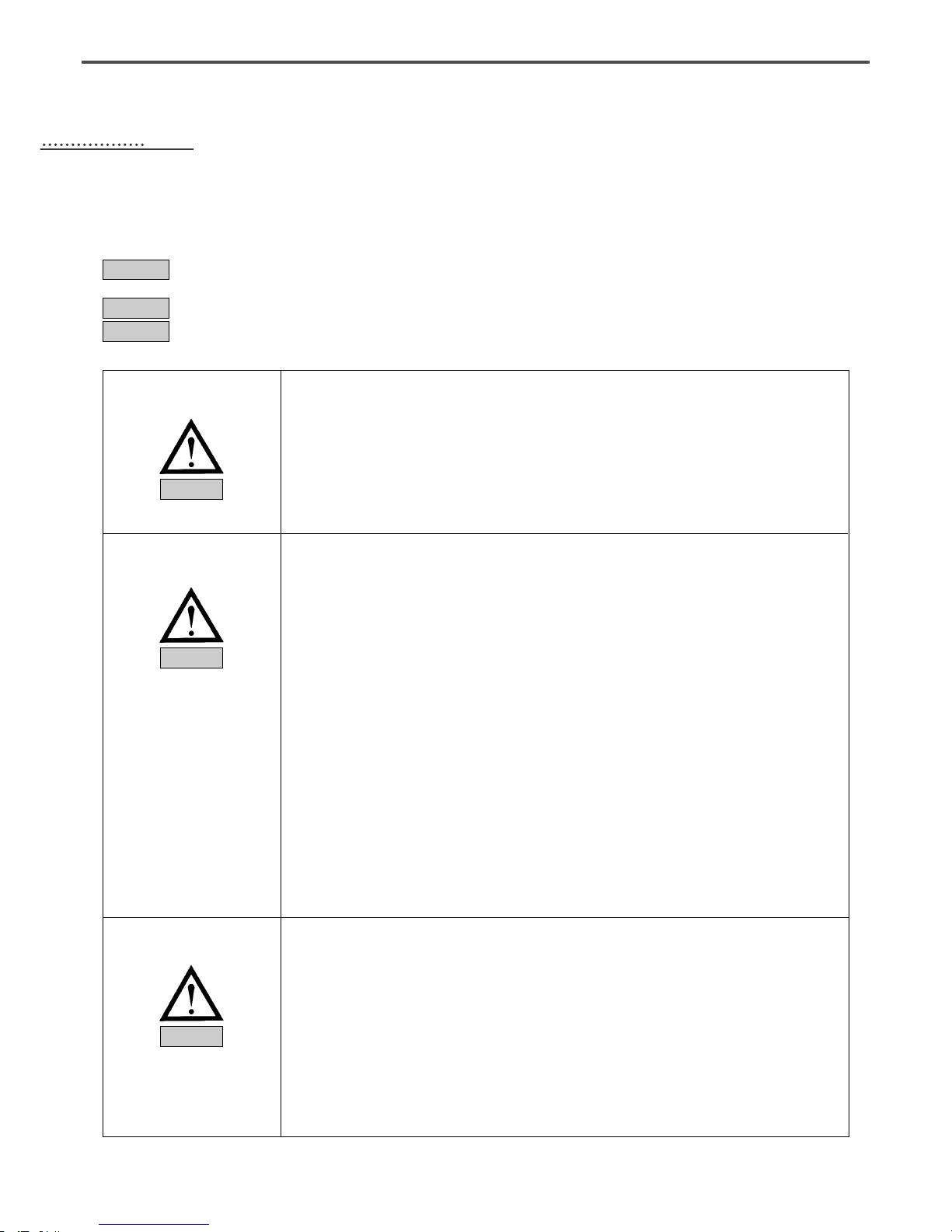
MACHINE SAFETY REGULATIONS
Safety instruction on this manual are defined as Danger, Warning and Notice.
If you do not keep the instructions, physical injury on the human body and machine damage might be occurred.
: This indication should be observed definitely. If not, danger could be happen during the installation,
conveyance and maintenance of machines.
: When you keep this indication, injury from the machine can be prevented.
: When you keep this indication, error on the machine can be prevented.
Danger
Warning
Notice
1-1) Machine
Transportation
Danger
1-2) Machine Installation
Warning
1-3) Machine Repair
Notice
Those in charge of transporting the machine should know the safety regulations very well.
The following indications should be followed when the machine is being transported.
ⓐ More than 2 people must transport the machine.
ⓑ To prevent accidents from occurring during transportation, wipe off the oil on the machine
well.
The machine may not work well or breakdown if installed in certain places, Install the machine
where the following qualifications agree.
ⓐ Remove the package and wrappings starting from the top. Take special notice on the nails
on the wooden boxes.
ⓑ Dust and moisture stains and rusts the machine. Install an airconditioner and clean the
machine regularly.
ⓒ Keep the machine out of the sun.
ⓓ Leave sufficient space of more than 50cm behind, and on the right and left side of the
machine for repairing.
ⓔ EXPLOSION HAZARDS
Do not operate in explosive atmospheres. To avoid explosion, do not operate this machine
in an explosive atmosphere including a place where large quantities of aerosol spray
product are being used or where oxygen is being administered unless it has been
specifically certified for such operation.
ⓕ The machine were not provided with a local lighting due to the feature of machine.
Therefore the illumination of the working area must be fulfilled by end user.
[Refer] Details for machine installment are described in Mechanical Structure Manual
4. Machine Installment.
When the machine needs to be repaired, only the assigned troubleshooting engineer educated at
the company should take charge.
ⓐ Before cleaning or repairing the machine, close down the motive power and wait 5
minutes till the machine is completely out of power.
ⓑ Not any of the machine specifications or parts should be changed without consulting the
company. Such changes may make the operation dangerous.
ⓒ Spare parts produced by the company should only be used for replacements.
ⓓ Put all the safety covers back on after the machine has been repaired.
7
A(B) Pattern Series is made to sew patterns on fabrics and other similar material for
manufacturing.
Follow the following indications when operating the machine.
ⓐ Read through this manual carefully and completely before operating the machine.
ⓑ Wear the proper clothes for work.
ⓒ Keep hands or other parts of the body away from the machine operation parts(needle,
shuttle, thread take-up lever, and pulley etc.) when the machine is being operated.
ⓓ Keep the covers and safety plates on the machine during operation.
ⓔ Be sure to connect the earthing conductor.
ⓕ Close down the electric motive power and check if the switch is turned “off”before opening
electric boxes such as the control box.
ⓖ Stop the machine before threading the needle or checking after work.
ⓗ Do not step on the pedal when turning the power on.
ⓘ Do not connect several motors to the same concent.
ⓙ If possible, install the machine away from loud noise such as high frequency welding
machines
ⓚ Be careful when the upper feed plate comes down to press. Otherwise, the finger or hand
might be hurt at smacking.
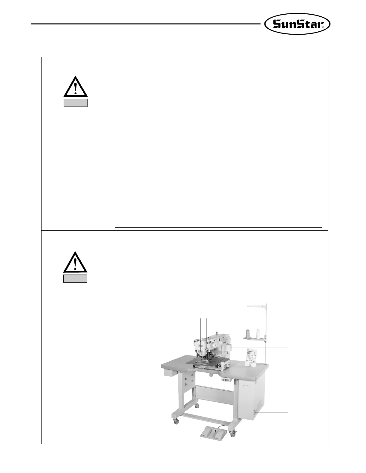
1-4) Machine Operation
Warning
ⓐ Safety label : It describes cautions during operating the machine.
ⓑ Thread take-up cover : It prevents from any contact between body and take-up lever.
ⓒ Belt Cover : It prevents from insertion of hands, feet or clothes by V-belt Motor.
ⓓ Step motor cover : It prevents from accidents during rotation of step motors.
ⓔ Label for specification of power : It describes cautions for safety to protect electric shock
during the motors’ rotation. (Voltage input / use Hz)
ⓕ Safety plate : It protects eyes against needle breaks.
ⓖ Finger guard : It prevent from contacts between a finger and needle.
1-5) Devices for Safety
[Warning]
Belt will crush or amputate finger or hand, keep cover in place before operating, turn off
power before inspecting or adjusting.
Notice
ⓐ
ⓑ
ⓓ
ⓐ
ⓔ
ⓒ
ⓕ
ⓖ
8
Caution
1)
2)
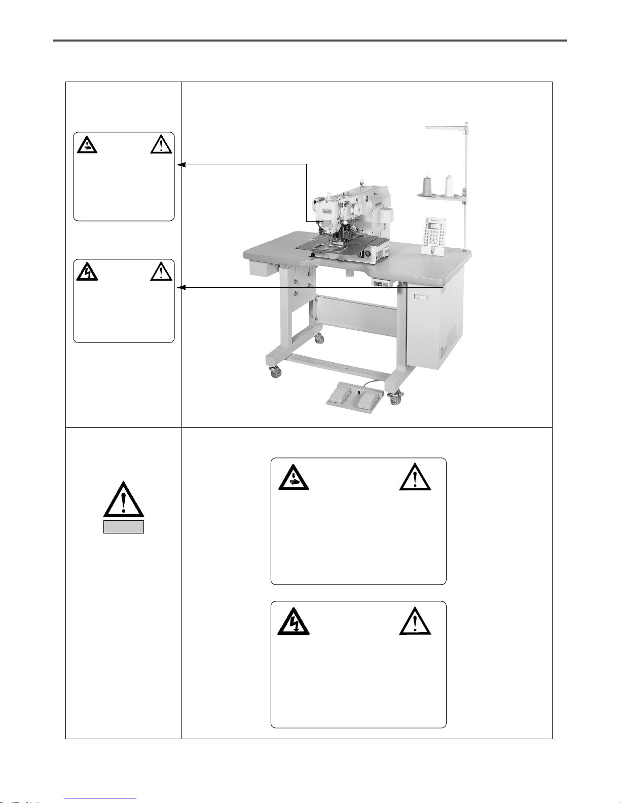
1-7) Contents of Marks
Warning
Caution mark is attached on the machine for safety.
When you operate the machine, observe the directions on the mark.
Position of Warning Mark
[View from the right-front]
1-6) Caution Mark
Position
CAUTION
경고
Do not operate without finger guard and
safety devices. Before threading, changing
bobbin and needle, cleaning etc. switch off
main switch.
손가락 보호대와 안전장치 없이 작동하지
마십시오.
실, 보빈, 바늘교환시나 청소전에는 반드시 주
전원의 스위치를 꺼 주십시오.
WARNING
경고
Hazardous voltage will cause injury.
Be sure to wait at least 360 seconds before
opening this cover after turn off main switch
and unplug a power cord.
고압 전류에 의해 감전될 수 있으므로 커버를
열 때는 전원을 내리고 전원 플러그를 뽑고 나
서 360초간 기다린 후 여십시오.
CAUTION
경고
Do not operate without finger guard
and safety devices. Before threading,
changing bobbin and needle, cleaning
etc. switch off main switch.
손가락 보호대와 안전장치 없이 작동하지 마
십시오.
실, 보빈, 바늘교환시나 청소전에는 반드시
주전원의 스위치를 꺼 주십시오.
WARNING
경고
Hazardous voltage will cause injury.
Be sure to wait at least 360 seconds
before opening this cover after turn
off main switch and unplug a power
cord.
고압 전류에 의해 감전될 수 있으므로 커버
를 열 때는 전원을 내리고 전원 플러그를 뽑
고 나서 360초간 기다린 후 여십시오.
9
22
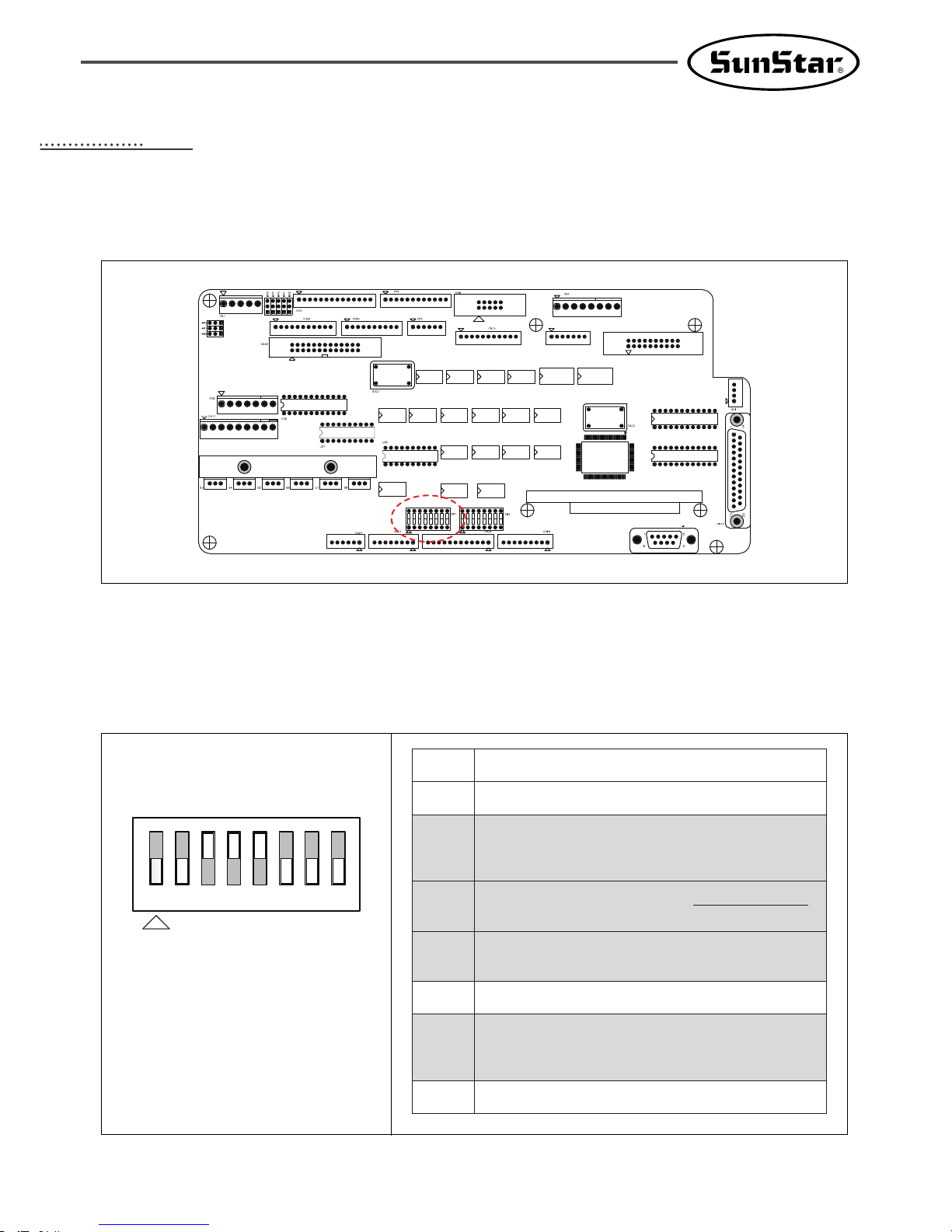
I/O Board Dip Switch Setting
This shows how to set up the dip switch(SW1) on the I/O board.
The figure above is based on the SPS/C-5050 I/O board.
The following describes each dip switch number.
SW1
1
2
Not used
Not used
3
Main shaft motor type
ON : Direct drive
OFF : Belt type
4
If the main shaft motor is a
ddiirreecctt ddrriivvee ttyyppee
,
activate the serial communication witht he CPU card.
5
6
7
8
New I/O board setting
(After REV 21)
Not used
Distinction between integrated and non-integrated versions
ON : Non-integrated version setting
OFF : Integrated version setting
Not used
10
33
BASIC OPERATIONAL METHOD
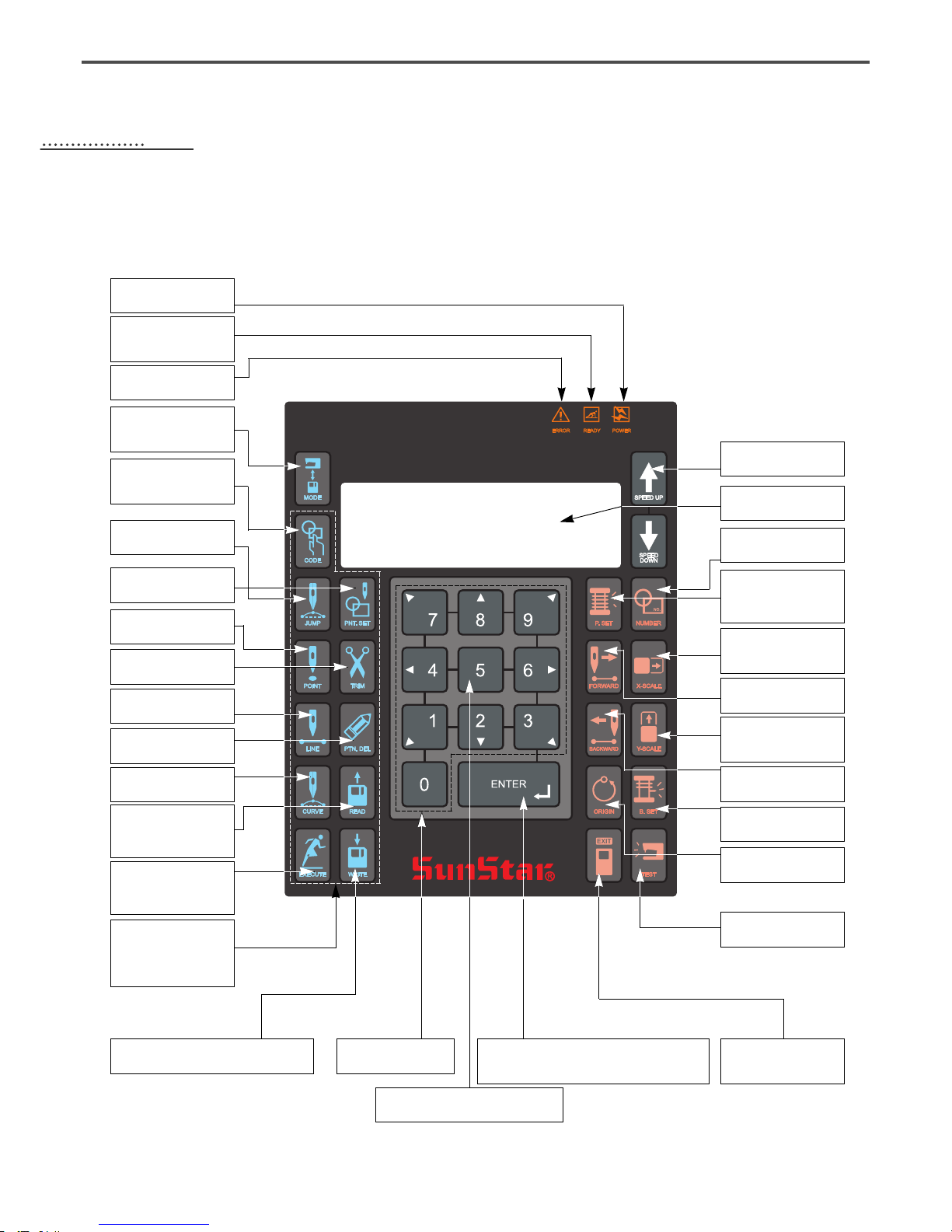
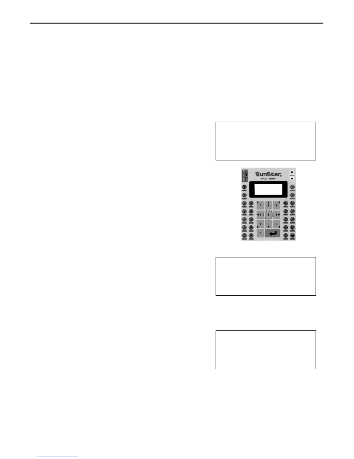
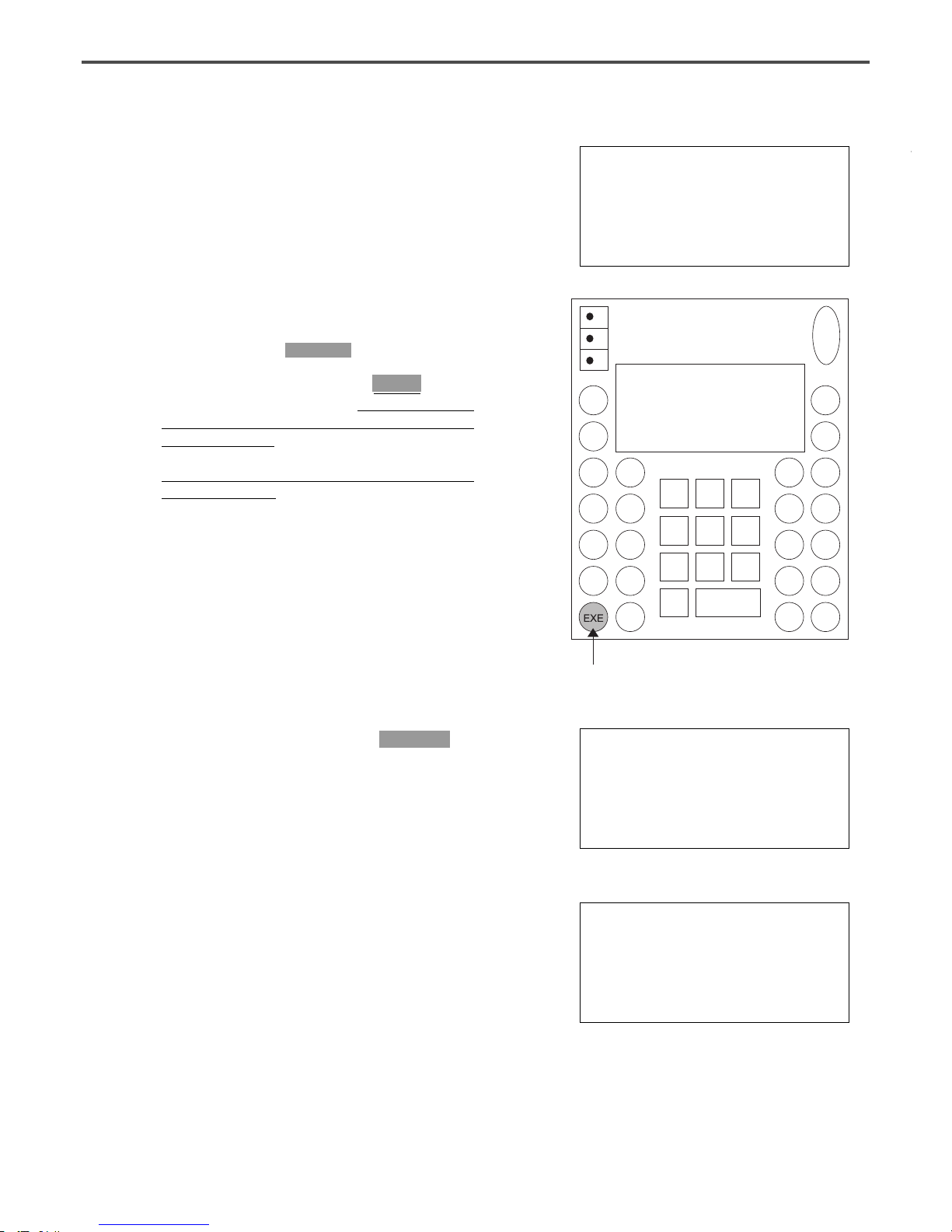
1) Name and Roles of Each Key on Operation Unit
POWER LED
Input of power
READY LED
Sewing available
condition
ERROR LED
Errors occurred
MODE KEY
Change of working
mode
CODE KEY
Selection of function
code
POINT KEY
Input of point code
JUMP KEY
Input of jump code
POINT-SET KEY
Input of point
TRIM KEY
Input of trim code
LINE KEY
Input of straight code
PATTERN-DELETE KEY
Delection of pattern code
CURVE KEY
Input of curve key
PUNCHING RELATED KEY
It can be used for pattern data generation
ENTER KEY
Pressed to cancle sewing function setups
or to end input
DIRECTION/DIGIT KEY
Threading and Unthreading Key
ESCAPE KEY
Cancle of function to
be selected
EXECUTION KEY
Designation of start
for code generation
WRITE KEY
Used to write the
pattern onto the
USB Flash Drive
READ KEY
Reading patterns from
a USB Flash Drive
NO. KEY
Input of pattern NO.
X_SCALE KEY
Use when it is extended or
reduced to the X direction
Y_SCALE KEY
Use when it is extended or
reduced to the Y direction
P. SET KEY
Counter setting for
working capacity
FORW KEY
1 Stitch forward
BACK KEY
1 Stitch backward
B. SET KEY
Counter setting of bottom thread
SPEED KEY
Change of sewing speed
LCD DISPLAY
Indication of contents
TEST KEY
Change to test sewing mode
ORIGIN KEY
Returning to origin
11
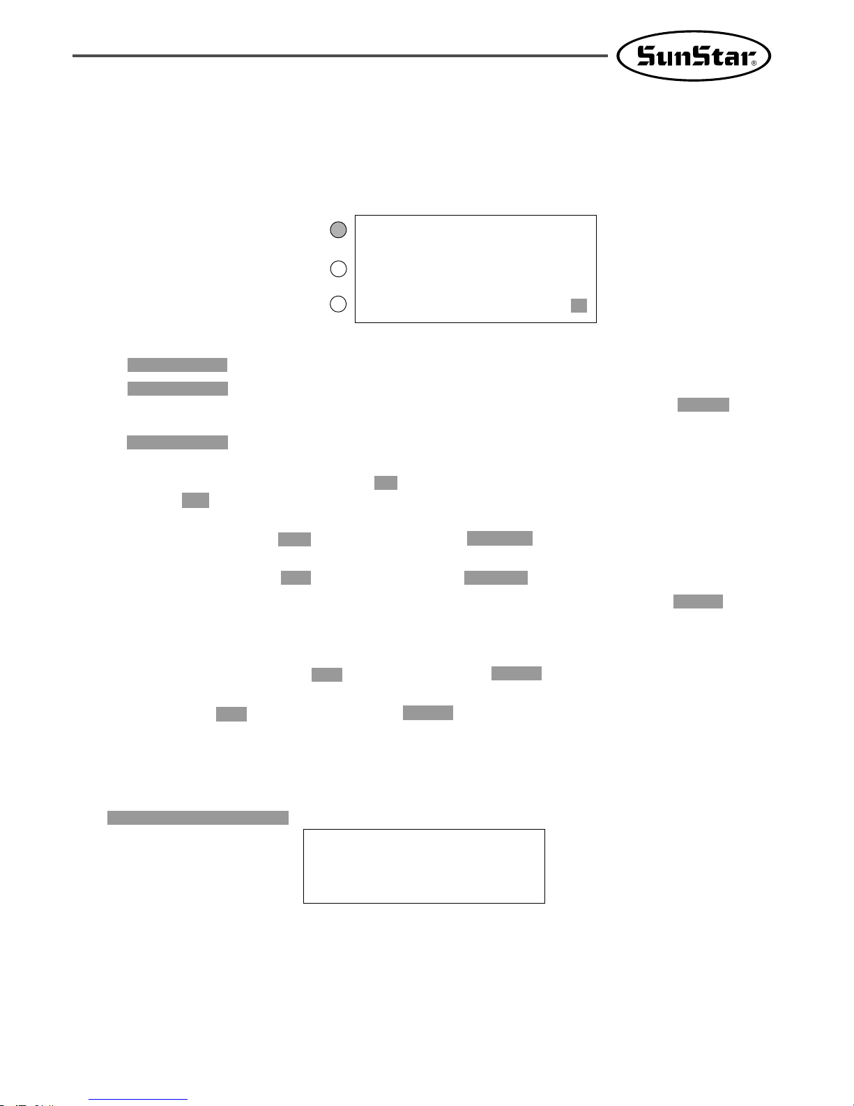
2) Name and Description of Each Display Contents on General Operation Mode
It is an initial screen when power is on for the first time, but display of screen can be changed according
to the general sewing related parameter.
A.
“POWER LED”:
When you turn on the power, this lamp also comes to light on.
B.“READY LED”:
This lamp comes to light on when a machine is ready to work by reading patterns.
During reading or writing the patterns, the lamp flickers. If you press ENTER, you
can get out of the “READY”state.
C.“ERROR LED”: When errors including sensing thread and emergency stop happen this lamp comes
to light on.
D.“NO”: It indicates pattern No. Press NO key and input the pattern number you want by pressing
digit keys. (000 ∼ 999)
E.“XS”: It indicates a rate of enlargement and reduction for width. You can change the value at your
option by using digit keys after pressing down X SCALE key. (001[%] ∼400[%])
F.“YS”: It indicates a rate of enlargement and reduction for length. You can change the value at your
option by using digit keys after pressing down Y SCALE key. (001[%] ∼400[%])
G.“SP”: It indicates sewing speed. You can change the speed you want by pressing down SPEED key.
(200[SPM] ∼2500[SPM])
※ Maximum sewing speed varies depending on the sewing machine. See “Setting-Up the Speed”.
H.“BC”: It indicates setting value of bottom thread exchange counter. You can change the value at
your option by using digit key after pressing down B. SET key. (000 ∼ 999)
I. “PC” : It indicates setting value of working capacity. You can change the value at your option by
using digit keys after pressing down P. SET key. (0000 ∼9999)
J. “NOR_SEW”: It shows working condition. General sewing and chain sewing are available.
“ NOR_SEW”indicates the general sewing and “CHN_XX”means chain sewing.
※ Reference : 00~15 are available in XX of “CHN_XX”
※ In case of SPS/C-series :
※ In case of SPS/C-series, when the power is on first, upper-lower shaft origin search motion will start. After
origin search motion, the highest position of thread take- up is set as the different way from the existing
pattern. Because origin search motion will perform to set upper-lower shaft hook time. This will not cause
problem during sewing or trimming. The position will be set as the existing pattern when the machine stops
or trims during sewing.
NO:000 NOR_SEW
XS:100%
YS:100% SP:1500
BC:000 PC:0000
POWER LED
READY LED
ERROR LED
Needle & Hook
Origin....
12
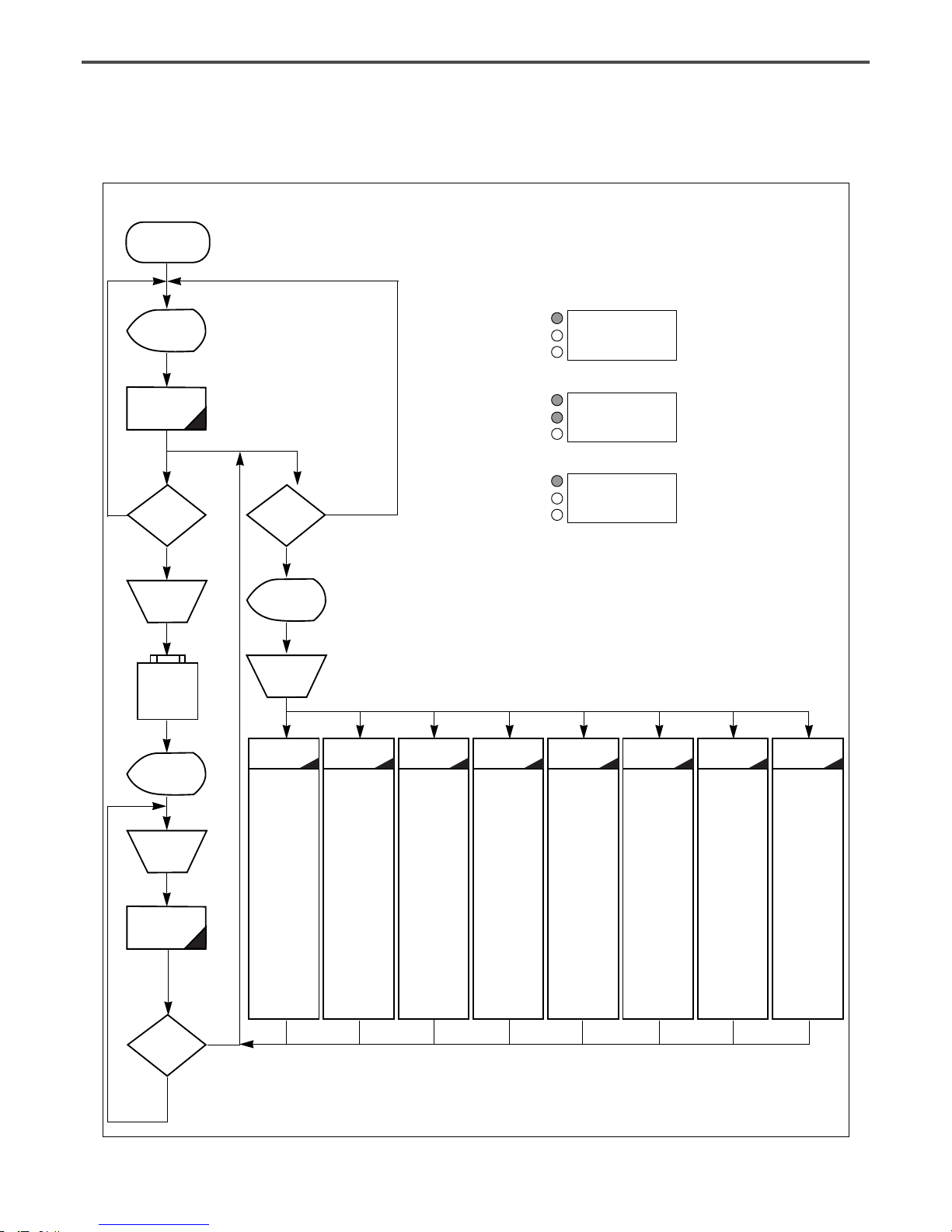
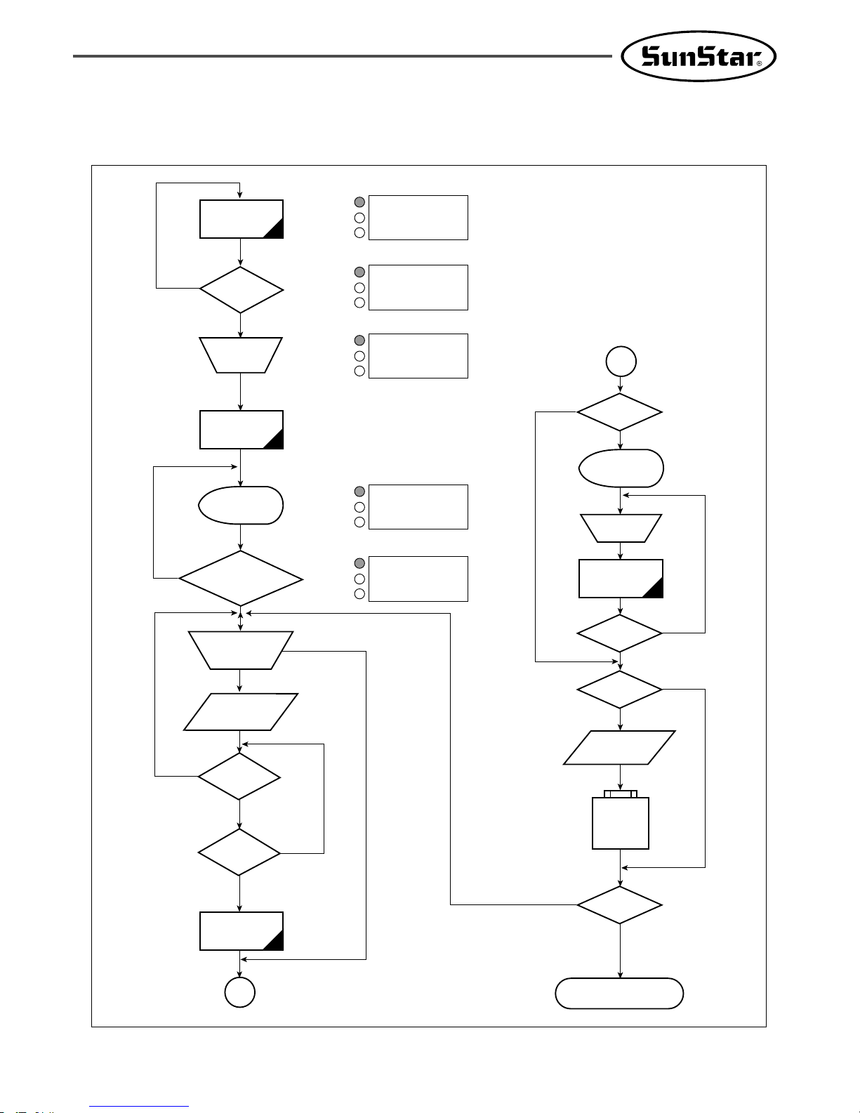
3) Flow Chart of General Operation
Power On
NO
NO
YES
NO
YES
YES
Indication of
general sewing
mode
General Sewing
mode
Is NO key
pressed?
Selection of
pattern No.
Read
USB flash
drive
Indication of
special working
mode
Selection of
working
mode
0:Initialization
1. S/W Version
2. Para. Init.
3. Sys. UpDate
4. Para Ptrn
1:Parameter
setting
0. JOG En/Dis
1. JOG Mode
2. Machine Org1
3. Machine Org2
4. Strt Ret Mod
5. Bobbin Counter
6. Prodct Counter
7. Pattern Read
8. Trim EM Stop
9. Slow Start
10. Max Speed
11. Feed End Pos
12. FF Operation
.
.
◎ Refer the
appendix 3.
2:Pattern
programming
0. TRIM
1. SEC_ORG
2. PAUSE
3. EMPTY
4. JUMP
5. POINT
6. LINE/CURVE
7. LINE
8. CURVE
9. ARC
10. CIRCLE
11. UMP SPD
12. STI SPD
.
.
◎ Refer the
appendix 4.
3:
Thread winding
4:Machine test
5:Pattern list
6:Embroidery
data conversion
7:JUKI Data
Conversion
0. Encoder Test
1. XY Main Test
2. MainMotor Test
3. Interrupt Test
4. PWM Test
5. LCD Test
6. Keyboard Test
7. Input0 Test
8. Input1 Test
9. Input2 Test
10. XY Jog Test
11. Solenoid Test
12. Origin Test
13. Jump Test
14. Asyne Test
(Direct Type)
0. Memory
1. USB
0. SWF
1. TAJIMA
JUKI(0)
Light On for
preparation
Operation of
pedal switch
Sewing
Is ENTER
key pressed?
Is MODE
key pressed?
NO:000 NOR_SEW
XS:100
%
YS:100%SP:2000
BC:000 PC:0000
POWER LED
READY LED
ERROR LED
POWER LED
READY LED
ERROR LED
POWER LED
READY LED
ERROR LED
NO:000 NOR_SEW
XS:100
%
YS:100%SP:2000
BC:000 PC:0000
<< Main Menu >>
0.Initialize
1.Parameter Set
2.Program
13
4) Work Flow of Pattern Programming
YES
NO
NO
NO
NO
YES
YES
YES
YES
YES
YES
NO
NO
NO
General
sewing mode
A
Is TEST key
pressed?
Light On for
preparation
Operation of
pedal switch
Test Sewing
Is TEST key
pressed?
Is WRITE key
pressed?
Input of Pattern
No.
Read
USB flash
drive
Is MODE key
pressed?
End of Programming Mode
Selection of
working mode
Pattern
Programming
Mode
Is CODE key or
punching related
key pressed?
Indication of
Programming
Mode
Selection of
Programming Code
Information Input of
Stitch Width and
Coordinates
Is ESC key
pressed?
Is EXE key
pressed?
Pattern Data
Generation
A
Is MODE key
pressed?
NO:000 NOR_SEW
XS:100
%
YS:100%SP:2000
BC:000 PC:0000
POWER LED
READY LED
ERROR LED
POWER LED
READY LED
ERROR LED
POWER LED
READY LED
ERROR LED
POWER LED
READY LED
ERROR LED
POWER LED
READY LED
ERROR LED
<< Main Menu >>
0.Initialize
1.Parameter Set
2.Program
<< Main Menu >>
2.Program
3.Bobbin Wind
4.Machine Test
ORIGIN
X:00000A N:00000
Y:00000A
Function Code?
<Function Code>
000:TRIM
001:SEC_ORG
002:PAUSE
14
5) Operating After Reading the Patterns from USB flash drive
A. Insert the USB flash drive stored sewing
patterns into the terminal.
B. After pressing NO key, input the pattern
number by using digit keys. (If you want to
work with “001”pattern, press [0][0][1])
C. Press ENTER key. Read the pattern and
change to sewing available mode.
D. At the moment, the upper thread plate comes
to descend, then ascend again after moving to
the sewing start point. The READY LED
comes to light on.
E.
Press SPEED key and adjust the speed properly.
F. If you step on the pedal switch on the right
side, the upper feed plate comes to descend, and
if you step on the pedal switch on the left side,
the machine starts relevant work.
G. When you finish operating, the machine backs to
the origin or sewing start point, and the upper
feed plate comes to ascend.
6) Confirming the Working Pattern Read from the USB flash drive
A. Insert a USB flash drive into the terminal.
B.
After pressing NO key, input the pattern number
by using digit keys. (If you want to work with
“001”pattern, press [0][0][1])
C. Press ENTER key. Read the pattern and
change to sewing available mode.
D. At the moment, the upper thread plate comes
to descend, then ascend again after moving to
the sewing start point. The READY LED
comes to light on.
E.
Press SPEED key and adjust the speed properly.
F. If you step on the pedal switch on the right
side, the upper feed plate comes to descend.
G.
If you press FORW and BACK keys to progress
and reverse 1 stitch, you can confirm the real
shape to be sewn. If you press continuously, it
moves to the start or to the end of pattern
data consecutively.
H.
If you want to finish working, press ORIGIN key.
I. If you want to continue sewing at the forward
or backward point, step on the left pedal switch.
J. When you finish operating, the machine backs to
the origin or sewing start point, and the upper
feed plate comes to ascend.
NO:001 NOR_SEW
XS:100%
YS:100% SP:2000
BC:000 PC:0000
NO:001 NOR_SEW
XS:100%
YS:100% SP:1500
BC:000 PC:0000
NO:001 NOR_SEW
XS:100%
YS:100% SP:2000
BC:000 PC:0000
NO:001 NOR_SEW
XS:100%
YS:100% SP:1500
BC:000 PC:0000
※ Caution : If READY LED turns on or upper feed plate is under, some keys are not available.
It happened, operate the keys after lifting the upper feed plate or pressing ENTER key.
15
7) When a Machine Stops Operating During Sewing by the Thread Cut
A.
You can get the screen like a figure on the right side.
B. If you want to sew continuously at the same
position, insert thread again, then step on the
left pedal switch. If you want to sew at the 1
stitch forward or backward point, after moving
by using FORW and BACK key and step on
the left pedal switch.
C. If you want to stop operation and restart
sewing from the beginning, press ORIGIN key.
The feed plate moves to the origin or sewing
start point and ascend.
D. When you finish operating, the machine backs to
the origin or sewing start point, and the upper
feed plate comes to ascend.
8) Emergency Stop During Operation
A. The machine stops operating immediately by
pressing EMERGENCY STOP switch during
sewing. Then you can get the screen like a figure
on the right side.
B.
If you want to restart sewing from the beginning
after discontinuing it, Press the EMERGENCY
STOP switch once more to perform trimming.
(When manual trimming is set after emergency
stop) then press ORIGIN key. The feed plate
moves to origin then comes to ascend.
C. If you want to continue sewing, step on the left
pedal switch. If you finish every working, a
needle moves to origin and the upper feed plate
ascends.
Err18
Thread Broken!
NO:001 NOR_SEW
XS:100%
YS:100% SP:2000
BC:000 PC:0000
Err17
Emergency Stop!
NO:001 NOR_SEW
XS:100%
YS:100% SP:2000
BC:000 PC:0000
9) Winding the Thread
A. Inset the empty bobbin into a head of the
sewing machine.
B. Press MODE key.
C. Move to “3. Bobbin Wind” by using direction
keys , then press ENTER key. At this
time, the upper feed plate comes to descend.
D. If you step on the left pedal switch, thread
winding starts to progress, and if you step on
the left pedal switch one more time, thread
winding comes to discontinue temporarily.
E. If you finish the thread winding work, complete
the thread winding with the left pedal switch
or ESC key.
<< Main Menu >>
3. Bobbin Wind
4. Machine Test
5. Pattern List
<<Bobbin Wind>>
16
A. Sewing ready position
NO:001 NOR_SEW
XS:100%
YS:100% SP:1500
BC:001 PC:0001
10) Safety Functions
10-1) Threading and Cancellation Key
When the sewing machine is in the ready position, press No. 5 key for threading (the presser foot and
the clamp descend). While threading, a user might mistakenly step on the operation pedal, and start the
operation, causing a safety problem. To prevent accidents, the function to freeze the operation after
threading was added.
However, the operation freeze status can be canceled by pressing the same No. 5 key again.
B. Press No. 5 key for threading. The following
message is displayed on the screen, and all keys
become disabled. The sewing operation pedal
switch is also disabled.
Threading...
To Release...
Press(5) again!
C. To cancel the freeze mode, press No. 5 key again.
D. When the safety mode is cancelled, the screen
returns to the original status.
NO:001 NOR_SEW
XS:100%
YS:100% SP:1500
BC:001 PC:0001
17
A. Press MODE and move to “Parameter Set”
on the Main Menu.
B. Press ENTER to get into “Parameter
Set”. Move to “095. Safety Mode”.
<< Main Menu >>
1. Parameter Set
2. Program
3. Bobbin Wind
<Parameter Set>
095.Safety Mode
096.Jump Speed
097.Auto Call
10-2) Emergency Stop, Thread Sensing or Pause Code.
In order to provide maximum safety to users, when a sewing machine is stopped due to emergency stop,
thread sensing or pause code, the operation of the pedal start switch, the clamp up/down switch and
the operation box keys become disabled. When the safety mode is cancelled, the keys are enabled again
and the sewing machine operation is back to normal.
To cancel the safety function, press the “
EXE”key on the left bottom of the OP Box. When this key
is pressed, the sewing machine operation will go back to normal.
When the sewing machine is stopped in relation to emergency stop, thread sensing or pause code, the
clamp takes the down position.
The safety mode can be set as follows:
C. The default value is 1) DISABLE.
095.Safety Mode
1) DISABLE <-
2) ENABLE
D. To activate the safety mode, move the cursor
to 2) ENABLE and press ENTER .
E. If the setting is completed, the safety mode
will be enabled in time of emergency stop,
thread sensing or pause code while sewing is
conducted.
095.Safety Mode
1) DISABLE
2) ENABLE <-
18
F. The following shows an example of situations
where the safety mode is activated. Thread is
broken in the middle of sewing.
When the thread is sensed, an alarm is issued
and the OP Box displays the following
message. While the message is displayed on
the OP Box screen, Pedal Start Switch,
Clamp Up/Down Switch, and Keys of the OP
Box remain disabled in order to protect users.
Only when the exit key is entered, the
functions mentioned above are operable. To
cancel the safety mode, press “
EXE” on the
left bottom of the OP Box. When this key is
pressed, the sewing machine operation will go
back to normal.
While the safety mode is effective, the clamp
is located down.
G. To cancel this function, press EXE Key on
the OP Box. This is the message you can
see on the OP Box screen.
After the function is cancelled, the sewing
machine can be operated again.
Err18
Thread Broken!
Press EXE Key
Sewing is ready
OK!
H. Sewing can be started by pressing the Pedal
Start Switch.
NO:003 NOR_SEW
XS:100%
YS:100% SP:2000
BC:100 PC:0000
NO:123 NOR_SEW
XS:100%
YS:100% SP:1500
BC:004 PC:9084
19
1) Pattern Data Generation Function
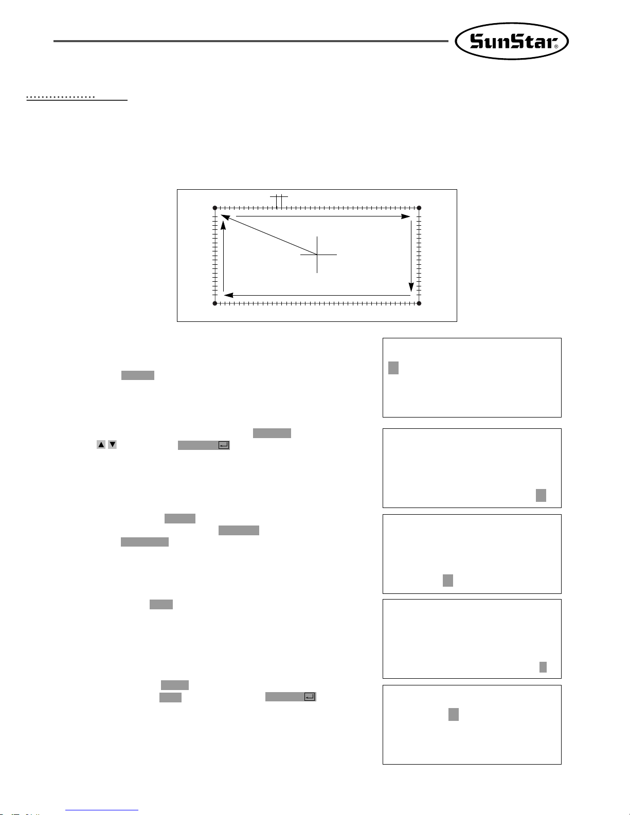
1-1) Program Example 1 : Generating the Square Pattern
(0,0)
Move
3mm
→
→
JUMP
P1
P4
P2
P3
(-650,-300) (650,-300)
(-650,300)
(650,300)
A. Insert a USB flash drive into the terminal.
B. Press MODE key.
C. Move to “2. Program” by using direction keys
, then press ENTER key. At this time,
the upper feed plate comes to descend.
D. After pressing JUMP key, move to the initial
point of square by using direction keys. Then,
press PNT SET key.
E.
If you press EXE key, the machine operates pattern
data, then the feed plate moves according to the
operated data.
F
.
After pressing LINE key, input the stitch width
by using the digit keys, then press ENTER
key. (For example, if you want to set the
stitch width as 3mm, input [0][3][0].)
<< Main Menu >>
2. Program
3. Bobbin Wind
4. Machine Test
ORIGIN
X:00000A N:00000
Y:00000A
Function Code?
JUMP NONE
X:-0650A N:00065
Y:00300A
Function Code?
007:LINE
WIDTH:030[0.1mm]
004:JUMP
X:-0650
Y:00300
N:001
44
APPLICABLE OPERATION
20
G. Move to each edge of the square by using
direction keys, then press PNT SET key to input
coordinates of each edge point. Whenever you
press the PNT SET key, the number on screen
will be increased.
H. If you press EXE key, the machine operates
pattern data, then the feed plate moves according
to the operated data.
I. Press TRIM key to input the trimming code.
Then, “000:TRIM”appears on the screen for a
little while, and you can see the screen like
a figure on the right side.
J.
If you press FORW and BACK keys to progress
and reverse 1 stitch, you can confirm the real
shape to be sewn. Whenever you once press the
keys, you can see the operating form and
coordinates
at that time. If you want to perform
test sewing, goes to the next step directly. If
you press continuously, it moves to the start or
to the end of pattern data consecutively.
K. Press TEST key.
The upper feed plate moves to origin and to the
sewing start point, then goes up again. READY
LED lights up. Press SPEED key and adjust
the speed properly. Then if you step on the
pedal switch on the right side, the upper feed
plate comes to descend, and if you step on the
pedal switch on the left side, the machine starts
test sewing. If the test sewing is finished, the
upper feed plate moves to the sewing start
point, then comes to ascend.
L. Press TEST key one more time and finish the
test sewing. Then, the upper feed plate comes to
descend and moves to origin with the turning
off the READY LED.
M. Press WRITE key and input the number you
want to save by using digit keys, then press
ENTER key. (For example, if you want to
save a pattern number as 300, input [3][0][0].)
It you do that, the generated pattern data will
be saved in a floppy disk to that number.
During
saving the pattern, the READY LED
flickers.
LINE NONE
X:-0650A N:00193
Y:00300A
Function Code?
TRIM NONE
X:-0650A N:00194
Y:00300A
Function Code?
<Test Sewing>
SP:1200
ORIGIN
X:00000A N:00000
Y:00000A
Function Code?
LINE NONE
X:-0650A N:00193
Y:00300A
Function Code?
015:PTRN WRITE
NO :300
007:LINE
X:-0650
Y:00300
N:004
21
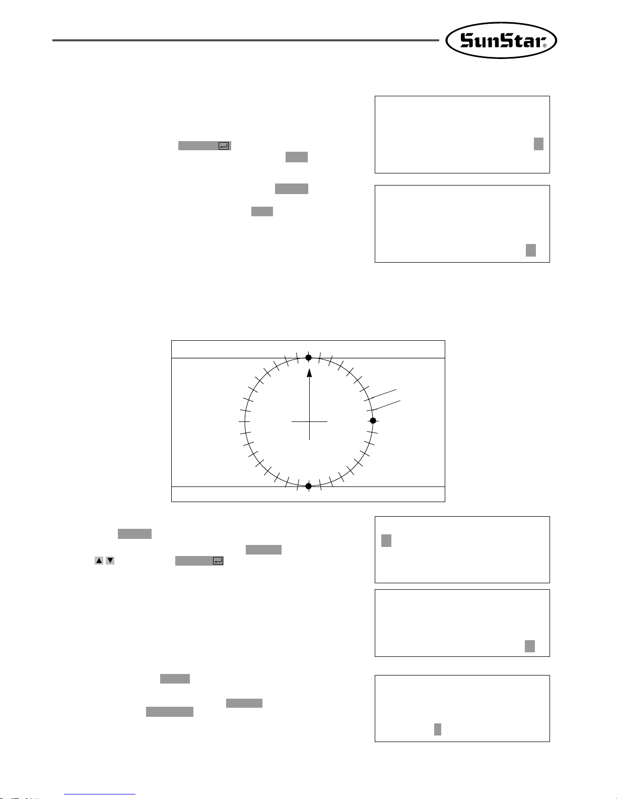
1-2) Program Example 2 : Generating the Circle Pattern
To generate circle patterns, input 3 random coordinates that pass on the circle.
A. Insert a USB flash drive into the terminal.
B. Press MODE key.
C. Move to “2. Program”by using direction keys
, then press ENTER key. At this time,
the upper feed plate comes to descend.
D. After pressing JUMP key, move to a random
coordinates (For example, X:00000, Y:00300)
that passes on circle by using direction keys.
Then, press PNT SET key.
O. For finishing a pattern generation, press MODE
key. Then, the upper feed plate moves to the
origin and comes to ascend. Press ESC key to
back to the initial screen.
N. If there already exists the pattern number that
you want to save in a USB flash drive, you can
see the screen like a figure on the right side. If
you
want to save the pattern with the same
number,
just press ENTER key, but if you
want to save it with another number, press ESC
key and save to the other number.
<< Main Menu >>
2. Program
3. Bobbin Wind
4. Machine Test
ORIGIN
X:00000A N:00000
Y:00000A
Function Code?
004:JUMP
X:00000
Y:00300
N:001
P1(0,300)
P1(0,-300)
P2(300,0)
(0,0)
↔
3mm
JUMP
Pattern Exist!
OverWrite?
Y(ENTER)/N(ESC)
ORIGIN
X:00000A N:00000
Y:00000A
Function Code?
22
JUMP NONE
X:00000A N:00027
Y:00300A
Function Code?
E. If you press EXE key, the machine operates
pattern data, then the feed plate moves according
to the operated data.
F. After pressing CODE key, if you know function
codes related to pattern programming, input three
digit number, but if not, move to “10. Circle”
by using direction keys after pressing
ENTER key, then press ENTER key again.
G. Input the stitch width by using the digit keys,
then press ENTER key. (For example, if you
want to set the stitch width as 3mm, input
[0][3][0].)
H. Move to the second random coordinates that
passes on a circle (For example, X:00300
Y:00000) by using direction keys, then press PNT
SET key.
Same as above,
move to the third
random coordinates that passes on a circle (For
example, X:00000 Y:-00300), then press PNT
SET key. Whenever you press PNT SET key,
the number of screen increases.
I. If you press EXE key, the machine operates
pattern data, then the feed plate moves according
to the operated data.
J. Press TRIM key to input the trimming code.
Then, “000:TRIM”appears on the screen for a
little while, and replace the screen like a
figure on the right side.
K.
If you press FORW and BACK keys to progress
and reverse 1 stitch, you can confirm the real
shape to be sewn. Whenever you once press the
keys, you can see the operating form and
coordinates
at that time. If you want to perform
test sewing, goes to the next step directly.
If you
press continuously, it moves to the start or to
the end of pattern data consecutively.
L. Press TEST key.
The upper feed plate comes to ascend and
moves to the origin or sewing start point, then
goes up. After that, READY LED turns on.
Press SPEED key and adjust the speed properly.
Then if you step on the pedal switch on the
right side, the upper feed plate comes to descend,
and if you step on the pedal switch on the left
side, the machine starts test sewing. If the test
sewing is finished, the upper feed plate moves to
origin and comes to ascend.
<Function Code>
010:CIRCLE <
011:JUMP SPD
012:STI SPD
010:CIRCLE
WIDTH:030[0.1mm]
010:CIRCLE
X:00000
Y:-0300
N:002
CIRCLE NONE
X:00000A N:00090
Y:00300A
Function Code?
CIRCLE NONE
X:00000A N:00090
Y:00300A
Function Code?
<Test Sewing>
SP:1500
TRIM NONE
X:00000A N:00091
Y:00300A
Function Code?
23
O. For finishing a pattern generation, press MODE
key. Then, the upper feed plate moves to the
origin and comes to ascend. Press ESC key to
back to the initial screen.
ORIGIN
X:00000A N:00000
Y:00000A
Function Code?
<< Main Menu >>
2. Program
3. Bobbin Wind
4. Machine Test
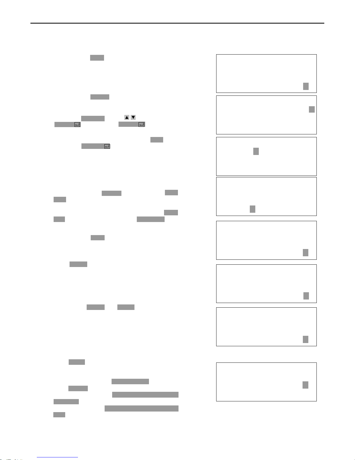
1-3) Program Example 3 : Generating the Double Curve Pattern
Input a curving spot that inclines largely among spots that pass on a curve. We give 5 curving lines for
examples here.
(-600,0)
(600,0)
(-300,200)
(300,-200)
(0,0)
A. Insert a USB flash drive into the terminal.
B. Press MODE key.
<< Main Menu >>
2. Program
3. Bobbin Wind
4. Machine Test
M.Press TEST key one more time and finish the
test sewing. Then, the upper feed plate comes to
descend and move to origin with the turning off
the READY LED.
N. Press WRITE key and input the number you
want to save by using digit keys, then press
ENTER key. Then, save the generated pattern
data in a USB flash drive as a relevant number.
(For example, if you want to save a pattern
number as 301, input [3][0][1].)
During saving the data, READY LED flickers.
If you want to save the pattern with the same
number, just press ENTER key, but if you
want to save it with another number, press ESC
key and save to the other number. After
finishing saving process, the upper feed plate
backs to the origin.
ORIGIN
X:00000A N:00000
Y:00000A
Function Code?
015:PTRN WRITE
NO :301
24
D. After pressing JUMP key, move to a random
coordinates (For example X:-0600, Y:00000)
that passes on a circle by using direction keys.
Then, press PNT SET key.
E. If you press EXE key, the machine operates
pattern data, then the feed plate moves according
to the operated data.
F. After pressing CODE key, If you know function
codes related to pattern programming, input
three digit number, but if not, move to “28.
Curve DBL”by using direction keys , after
pressing ENTER key, then press ENTER
key again.
G. Input the stitch width by using the digit keys,
then press ENTER key. (For example, if you
want to set the stitch width as 3mm, input
[0][3][0].) Input the distance between the two
curves by using digit keys, then press ENTER
key. (For example, if you want to set 5mm,
input [0][5][0].) Input a direction
from
standard curve by using digit keys, then
press
ENTER key. (For example, if you want to
place another curve on above the standard
curve, input [0].)
H. Move to the next coordinates (For example, X:-
0300 Y:00200) by using direction keys, then press
PNT SET key. Same as above, move to the
other three coordinates in turns by using direction
keys and press PNT SET key. At this time,
whenever you press PNT SET key, the number
of screen increases.
I. If you press EXE key, the machine operates
pattern data, then the feed plate moves
according to the operated data. At this time, the
sewing machine discontinues for a while.
JUMP NONE
X:-0600A N:00054
Y:00000A
Function Code?
<Function Code>
028:CURVE DBL <
029:ARC DBL
030:CIRCLE DBL
028:CURVE DBL
WIDTH:030[0.1mm]
OFSET:050[0.1mm]
DIR:0[0/1]
004:JUMP
X:-0600
Y:00000
N:001
028:CURVE DBL
X:00600
Y:00000
N:004
CURVE DBL NONE
X:-0635A N:00157
Y:00035A
Function Code?
C. Move to “2. Program”by using digit keys ,
then press ENTER key. At this time, the
upper feed plate comes to descend and moves to
the origin.
ORIGIN
X:00000A N:00000
Y:00000A
Function Code?
25
J. Press TRIM key to input the trimming code.
Then, “000:TRIM”appears on the screen for a
little while, and you can see the screen like
a figure on the right side.
K.
If you press FORW and BACK keys to progress
and reverse 1 stitch, you can confirm the real
shape to be sewn. Whenever you once press the
keys, you can see the operating form and
coordinates at that time. If you want to perform
test sewing, goes to the next step directly. If
you press continuously, it moves to the start or
to the end of pattern data consecutively.
L. Press TEST key.
The upper feed plate comes to ascend and moves
to origin, then goes up. After that, READY
LED lights up. Press SPEED key and adjust
the speed properly. Then if you step on the
pedal switch on the right side, the upper feed
plate comes to descend, and if you step on the
pedal switch on the left side, the machine starts
test sewing. If the test sewing is finished, the
upper feed plate moves to origin or sewing start
point and comes to ascend.
M. Press TEST key one more time and finish the
test sewing. Then, the upper feed plate comes to
descend and moves to origin with the turning on
the READY LED.
N. Press WRITE key and input the number you
want to save by using digit keys, then press
ENTER key. Then, save the generated
pattern data in a USB flash drive as a relevant
number.(For example, if you want to save a
pattern number as 302, input [3][0][2].)
During saving the data, READY LED flickers.
If you want to save the pattern with the same
number, just press ENTER key, but if you
want to save it with another number, press
ESC key and save to the other number. After
finishing saving process, the upper feed plate
backs to the origin.
O.
For finishing a pattern generation, press MODE
key. Then, the upper feed plate comes to ascend
after moving to origin. Press ESC key to
back to the initial screen.
CURVE DBL NONE
X:00600A N:00103
Y:00000A
Function Code?
<Test Sewing>
SP:1500
ORIGIN
X:00000A N:00000
Y:00000A
Function Code?
ORIGIN
X:00000A N:00000
Y:00000A
Function Code?
015:PTRN WRITE
NO :302
<< Main Menu >>
2. Program
3. Bobbin Wind
4. Machine Test
TRIM NONE
X:-0635A N:00158
Y:00035A
Function Code?
26
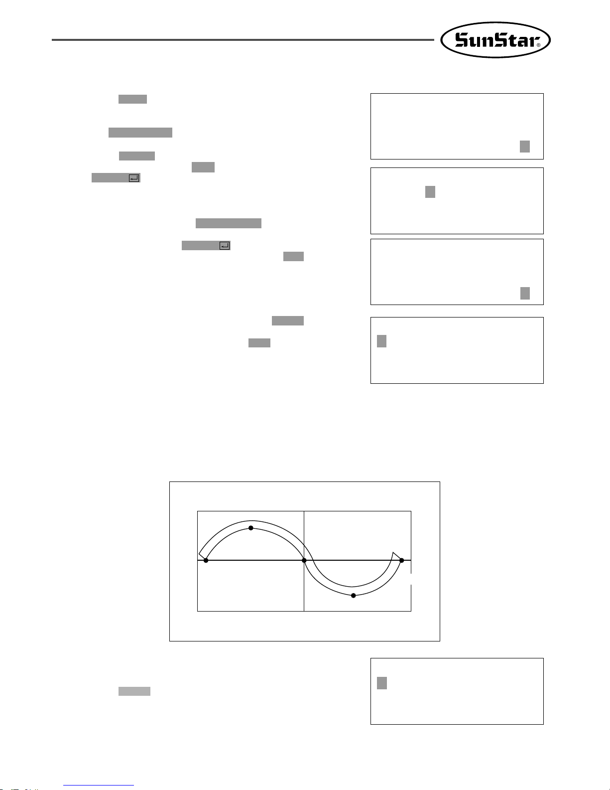
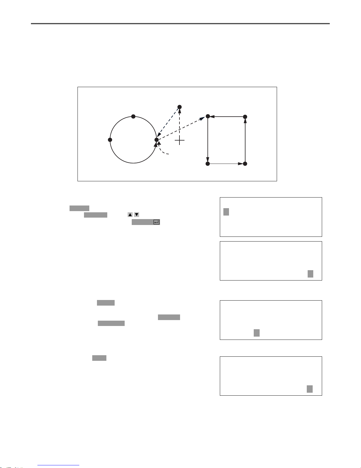
1-4) Program Example 4 : Pattern Generation by Using the Second Origin and Pause
To program as below, input as the following orders : JUMP → SEC_Org → JUMP → CIRCLE →
TRIM → PAUSE → JUMP → LINE → TRIM
P1
(PAUSE)
(0,0)
(JUMP)
D. After pressing JUMP key, make the second
origin move to the coordinates (For example,
X:00000 Y:00300) you want by using direction
keys, then press PNT SET key.
E. By pressing EXE key, after operating the
pattern data, the feed plate moves according to
the operated pattern data.
004:JUMP
X:00000
Y:00300
N:001
JUMP NONE
X:00000A N:00027
Y:00300A
Function Code?
ORIGIN
X:00000A N:00000
Y:00000A
Function Code?
A. Insert a USB flash drive into the terminal.
B. Press MODE key.
C. By using direction keys , move to “2.
Program” menu, then press ENTER key. At
this time the upper feed plate descends, and
moves to the origin.
<< Main Menu >>
2. Program
3. Bobbin Wind
4. Machine Test
(SEC_ORG)
P2
P3
(CIRCLE)
(LINE)
P5
P7
P4
P6
27
<Function Code>
001:SEC_ORG <
002:PAUSE
003:EMPTY
F. After pressing CODE key, input the three digit
numbers if you know the pattern programming
related function code, but if you don’t know it,
press ENTER key and move to “001: SEC_
ORG”by using direction keys , then press
ENTER key again.
G. After pressing JUMP key, move to one random
coordinates that passes through circle (for
example, X:-0100, Y:00000), then press PNT
SET key.
H. By pressing EXE key, the feed plate moves
according to the operated data after operating
the pattern data.
I. After pressing CODE key, input the three digit
numbers if you know the pattern programming
related function code, but if you don’t know it,
press ENTER key and move to “010: Circle”
by using direction keys , then press ENTER
key again.
J. By using digit keys, input the stitch width and
press ENTER key.
(For example, if you set up the stitch width as
3mm, input [0][3][0].)
K. By using direction keys, move to the second
random coordinates that passes through circle
(for example, X:-0300 Y:00200), then press
PNT SET key.
Likewise move to the third coordinates that
passes through circle (for example, X:-0500
Y:00000), then press PNT SET key.
At this time the number on screen increases
whenever you press PNT SET key.
JUMP NONE
X:-0100A N:00056
Y:00000A
Function Code?
<Function Code>
010:CIRCLE <
011:JUMP SPD
012:STI SPD
010:CIRCLE
WIDTH:030[0.1mm]
010:CIRCLE
X:-0500
Y:00000
N:002
004:JUMP
X:-0100
Y:00000
N:001
28
CIRCLE NONE
X:-0100A N:00098
Y:00000A
Function Code?
TRIM NONE
X:-0100A N:00099
Y:00000A
Function Code?
<Function Code>
002:PAUSE <
003:EMPTY
004:JUMP
004:JUMP
X:00100
Y:00200
N:001
JUMP NONE
X:00100A N:00125
Y:00200A
Function Code?
<Function Code>
007:LINE <
008:CURVE
009:ARC
L.
By pressing EXE key, the feed plate moves
according to the operated data after operating
the pattern data.
M.
By pressing TRIM key, input the code for trim.
Then, after appearing “00:TRIM”on the screen
for a moment, then a screen of the right side
appears.
N.
After pressing CODE key, input the three digit
numbers if you know the pattern programming
related function code, but if you don’t know it,
press ENTER key and move to “002: PAUSE”
by using direction keys , then press ENTER
key.
O.
After pressing JUMP key, move to the one
random coordinates of straight line (for example,
X:00100 Y:00200)by using direction keys, then
press PNT SET key.
P.
By pressing EXE key, the feed plate moves
according to the operated data after operating
the pattern data.
Q. After pressing CODE key.
If you know the function number related to
pattern programming, input three-figure number
and if you do not know the number, press
ENTER key and transfer to “007:Line”menu
by using direction key , and then press
ENTER key.
Ref.)“LINE”and “CURVE”function is set to
use with hot key on the operation
panel and so you may press this key.
29
007:LINE
WIDETH:030[0.1mm]
007:LINE
X:00100
Y:00200
N:004
LINE NONE
X:00100A N:00181
Y:00200A
Function Code?
TRIM NONE
X:00100A N:00182
Y:00200A
Function Code?
015:PTRN WRITE
NO :303
ORIGIN
X:00000A N:00000
Y:00000A
Function Code?
<< Main Menu >>
2. Program
3. Bobbin Wind
4. Machine Test
R.
By using the digit keys, input the stitch width
and press ENTER key.
(For example, if you set up the stitch width as
3mm, input [0][3][0].)
S.
By using direction key, move to the another
coordinates in turns that passes through line,
then press PNT SET key.
At this time the number on screen increases
whenever you press PNT SET key.
T.
By pressing EXE key, the feed plate moves
according to the operated data after operating
the pattern data.
U.
By pressing TRIM key, input the code for trim.
Then, after appearing “00:TRIM”on the screen
for a moment, then a screen of the right side
appears.
V.
After pressing WRITE key, input the number
you want to save by using digit keys. then
press ENTER key. Save the generated pattern
data in a USB flash drive as a relevant number.
(For example, if you want to save the pattern
number as 303, input [3][0][3].) During saving
the pattern, the READY LED flickers. When a
pattern of same number is in a USB flash drive
and if you want to save another pattern as
same number, press ENTER key. If you want
to save the pattern as another number, press
ESC key and save it as another number. After
finishing saving, the upper feed plate moves to
the origin again.
W.
For finishing pattern generation, press MODE
key. Then the upper feed plate moves to the
origin and ascends. Press ESC key to back to
the initial screen.
30
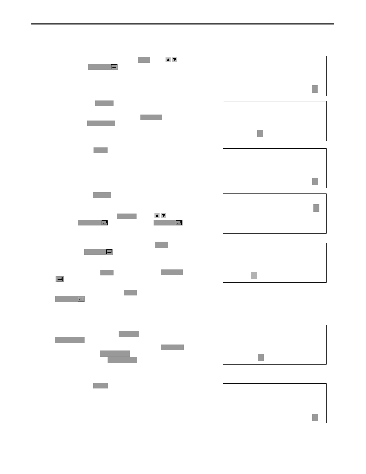
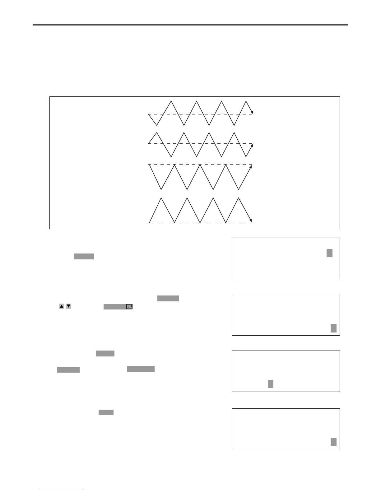
1-5) ZigZag Shape Selecting Function to Generate ZigZag
It was made to select 4 kinds of “DIR” values from existing 0/1 to 0/1/2/3 among three parameters
inputting to create Line ZigZag, Curve ZigZag, Arc ZigZag, Circle ZigZag and accordingly ZigZag shapes
are classified into 4 type.
JUMP
X:-0650A
Y:00000A
N:001
JUMP NONE
X:-0650A N:00000
Y:00000A
Function Code?
ORIGIN
X:00000A N:00000
Y:00000A
Function Code?
C. Move to “2. Program”menu by using direction key
and press ENTER key. Then, the upper
feed plate comes down and moves the original
point.
A. Insert a USB flash drive into the terminal.
B. Press MODE key.
D. After pressing JUMP key, move to the coordinate
(for example:X:-0650 Y:00000) to locate by using
direction key. Then, press PNT SET key.
E. If you press EXE key, after calculation on
pattern data, feed plate moves according to the
calculated data.
<< Main Menu >>
2. Program <
3. Bobbin Wind
4. Machine Test
For DIR=0
For DIR=1
For DIR=2
For DIR=3

31
<Function Code>
019:LINE ZIG <
020:CURVE ZIG
021:ARC ZIG
G. Input ZigZag width by using digit key, press
ENTER key and input ZigZag stitch width.
Then, press ENTER key and input DIR value
by using digit key to select ZigZag shape to
create. And press ENTER key.
H. Move ZigZag line (Ex: X: 00650 Y: 00000) to
the last sewing coordinate by using direction key
again and press PNT SET key.
F. After pressing CODE key, if you know the
function number related to pattern programming,
input three figure digit number and if you do
not know the number, press ENTER key. Then
after moving to “019: LINE ZIG” menu by
using direction key, press ENTER key.
J. Input thread trimmer key by pressing TRIM
key. Then “00:TRIM” screen appears for a
second and then the screen like the figure in the
right side appears again.
I. If you press EXE key, after calculation on
pattern data, feed plate moves according to the
calculated data.
K. You can confirm the shape to be actually sewed
by pressing FORW key and BACK key. Every
time you press once, it moves by one stitch and
show work mode and coordinate at the moment.
When you want to actually do initial sewing,
skip to next. If you press continuously, it moves
to the start or to the end of pattern data
consecutively.
L. Press TEST key. The upper feed plate moves to the
original point or sewing start point and goes up
and READY LED is turned on. After adjusting
appropriate initial sewing speed by pressing SPEED
key, step on the pedal switch in the right. Then, the
upper feed plate comes down and stepping on the left
pedal, it performs initial sewing. The upper feed plate
that completed initial sewing moves to the original
point or sewing start point and then goes up.
M. The order of saving and completion is the same
as the previous example.
017:LINE ZIG
X:00650
Y:00000
N:001
LINE ZIG NONE
X:00650A N:00000
Y:00000A
Function Code?
TRIM NONE
X:00650A N:00000
Y:00000A
Function Code?
LINE ZIG NONE
X:00650A N:00000
Y:00000A
Function Code?
<Test Sewing>
SP:1500
010:LINE ZIG
WIDTH:030[0.1mm]
PITCH:030[0.1mm]
DIR:3[0->3]

32
2) Pattern Data Edit Function
2-1) One Stitch Movement Function
It uses when correcting the location of one stitch in the formed sewing shape.
014:PTRN READ
NO :001
LINE
X:-0001A N:00059
Y:00000A
Function Code?
ORIGIN
X:00000A N:00000
Y:00000A
Function Code?
A. Insert USB flash drive containing the pattern to
change movement of a stitch.
B. Press MODE key.
C. After moving to “2. Program” menu by using
direction key , press ENTER key. At this
time, the upper feed plate comes down and
move the original point.
D. After pressing READ key, input the pattern
number to change movement of a stitch by
moving the digit key and read in the pattern by
pressing ENTER key. (For example, to read
pattern number 001, input [0][0][1]).
E. Go to the location of stitch to correct by using
FORW and BACK key.
<Function Code>
051:STITCH DRAG<
052:STITCH DEL
053:MOV SEWSTAR
F. After pressing CODE key, if you know the
function number 051 related to pattern
programming, input three figure of digit number
and if you do not know the number, press
ENTER key and move to “051:STITCH
DRAG”by using direction key . Then, press
ENTER key.
<< Main Menu >>
2. Program <
3. Bobbin Wind
4. Machine Test
Existing Location
Location Movement
New Location
< Before Location Change > < After Location Change >

33
051:STITCH DRAG
X:-00001
Y:-00060
N:000
H. If you press EXE key, change to new needle
location is completed.
I. Confirm if needle location was changed to the
desired location by using FORW and BACK
key.
G. Move to the location desired movement of one
stitch by using direction key.
※
X-Y coordinate value is different according
to location of needle.
A. Insert partial pattern data into the USB flash
drive containing the pattern to move and
change.
B. Press MODE key.
<< Main Menu >>
2. Program <
3. Bobbin Wind
4. Machine Test
LINE
X:-0001A N:00059
Y:-0060A
Function Code?
2-2) Partial Movement Function of Pattern Data
Move part of pattern to different location among the sewing shape.
End Point of Movement ScopeStart Point of Movement Scope
Scope to Move
Location to Move
< Before Movement > < After Movement >
ORIGIN
X:00000A N:00000
Y:00000A
Function Code?
C. After moving to “2. Program” menu by using
direction key , press ENTER key. At this
time, the upper feed plate comes down and
moves to the original point.

34
D. After pressing READ key, input the pattern
number to move and change partial pattern
data by using digit key and read in the pattern
by pressing ENTER key. (For example, input
[0][0][1] to read the pattern number 001.)
E. Go to the needle location to partially move by
using FORW and BACK key.
014:PTRN READ
NO :001
JUMP
X:00174A N:00070
Y:00183A
Function Code?
Reference) Location of the needle for partial movement
should be placed at the first start needle location that
actually sews. Therefore, if the sewing data that has
line property after jump appears, the last location of
JUMP data is the first start location of needle correction.
F. After pressing CODE key, if you know the
function number related to pattern programming,
input three figure digit number 046, but if you
do not know the number, press ENTER key.
Then after move to “046:MOV PTRN” by
using direction key , press ENTER key.
<Function Code>
046:MOV PTRN<
052:COPY PTRN
053:DEL PTRN
G. Go to the last location of pattern to move by
using FORW key.
※ The indicated values are different according
to current location.
<RANGE SETTING>
X:00174A N:00088
Y:00183A
H. If you press EXE key, it becomes the state
that the selected pattern for partial movement
can move to the optional location.
046:MOV PTRN
X:00174
Y:00183
N:000
I. Move to the location to move by pressing direction
key.
046:MOV PTRN
X:00174
Y:-0101
N:000
J. If you press EXE key, movement is completed.
K. Confirm if movement was properly made by
using FORW and BACK key.
LINE
X:00174A N:00096
Y:-00101A
Function Code?

35
A. Insert USB flash drive containing the pattern to
delete stitches.
B. Press MODE key.
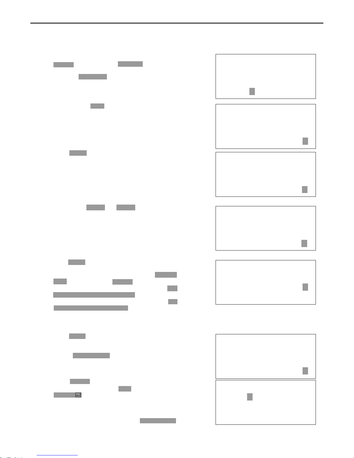
2-3) A Fixed Number of Stitch Delete Function
Delete 1-99 stitch in the pattern data shape after the start point to delete at present.
Delete Start PointDelete Start Point
Number of Stitch to delete Number of deleted Stitch
JUMP
< Before Delete > < After Delete >
ORIGIN
X:00000A N:00000
Y:00000A
Function Code?
C. After moving to “2. Program” menu by using
direction key , press ENTER key. At this
time, the upper feed plate comes down and
moves to the original point.
014:PTRN READ
NO :001
D. After pressing READ key, input the pattern
number to delete stitch by using the digit key
and read in the pattern by pressing ENTER
key. (For example, input [0][0][1] to read the
pattern 001.)
LINE
X:-0025A N:00059
Y:00000A
Function Code?
E. Go to needle location to delete by using FORW
and BACK key.
※ X-Y coordinate value is different according to
needle location.
<Function Code>
052:STITCH_DEL <
053:MOV SEWSTRT
054:MOV 2ndORG
F. After pressing CODE key, if you know the
function number 052 related to pattern
programming, input three-figure digit number
and if you do not know, press ENTER key.
Then after moving to “052:STITCH_DEL”by
using direction key , press ENTER key.

36
052:STITCH DEL
NUM:10[STITCH]
TRIM
X:-0233A N:00033
Y:00120A
Function Code?
G. Input the number of stitch to delete behind
from current location.
H. Press ENTER key.
I. Stitch is deleted as many as the input number.
J. Confirm if the stitches were deleted as many as
desired number by using FORW and BACK
key.
A. Insert USB flash drive containing the partial
pattern to delete.
B. Press MODE key.
Reference) After deleting as much as the number of
defined stitches, if end point and start point of two
sewing data existing at both sides do not match and
have distances, a jump is automatically made between
the two sewing data. If you want to input automatic
thread trimming, you can set up at “057:AUTO TRM”.
2-4) Partial Pattern Data Delete Function
Delete one of the generated pattern data shapes selectively (For example: Jump, Line, Curve, Arc, Circle).
LINELINE
LINE
LINE
LINE
CIRCLE
LINE
Needle Position
Needle Position
LINE
LINE
LINE
LINE
LINE LINE
LINE LINE
ARC ARC
ARC
CURVECURVE
CURVE CURVE
JUMP
< CIRCLE Delete > < LINE Delete >
< ARC Delete >
Needle Position

37
ORIGIN
X:00000A N:00000
Y:00000A
Function Code?
014:PTRN READ
NO :001
CIRCLE
X:-0067A N:00052
Y:-0092A
Function Code?
TRIM
X:-0220A N:00029
Y:00040A
Function Code?
C. After moving to “2. Program” menu by using
direction key press ENTER key. At this
time, the upper feed plate comes down and
moves to the original point.
D. After pressing READ key, input the pattern
number to delete partial pattern by using digit
key and read in the pattern by pressing
ENTER key. (For example, input [0][0][1] to
read the pattern number 001).
E. Go to the pattern that the shape to delete
exists by using FORW and BACK key.
※ X-Y coordinate value is different according
to needle location.
F. Delete is available by two methods as below.
- After pressing CODE key, input Function code
039 and press ENTER key.
- Or press PTN. DEL key of OP.
G. Press PTN.DEL key on operation box (OP).
Reference) After deleting as much as the number of
defined stitches, if end point and start point of two
sewing data existing at both sides do not match and
have distances, a jump is automatically made between
the two sewing data. If you want to input automatic
thread trimming, you can set up at “057:AUTO TRM”.
H. Confirm if desired partial pattern shape was
deleted by using FORW and BACK key. (Line
is deleted by once.)
I. Delete the partial pattern data to delete
repeatedly in the order of E-F-G.

38
2-5) Partial Stitch Width Changing Function
Change stitch width by selecting a fixed part from the pattern shape.
End Point of Stitch
Width Change
Start Point of Stitch
Width Change
End Point of Stitch
Width Change
Start Point of Stitch
width Change
Current Stitch Width 3.0mm
Current Stitch Width 2.0mm
< Before Partial Stitch Width Change > < After Partial Stitch Width Change >
ORIGIN
X:00000A N:00000
Y:00000A
Function Code?
014:PTRN READ
NO :001
A. Insert USB flash drive containing the pattern to
change stitch width.
B. Press MODE key.
C. After moving to “2. Program” menu by using
direction key , press ENTER key. At this
time, the upper feed plate comes to descend.
D. After pressing READ key, input the pattern
number to change stitch width by using digit
key and read in the pattern by pressing
ENTER key. (For example, input [0][0][1] to
read the pattern number 001.)
LINE
X:-0070A N:00021
Y:00140A
Function Code?
E. Go to the location to start change of stitch
width by using FORW and BACK key.
※ X-Y coordinate value is different according
to needle location.

39
<Function Code>
013:STI WIDT<
014:PTRN READ
015:PTRN WRITE
013:STI READ
WIDTH:020[0.1mm]
<RANGE SETTING>
X:00142A N:00029
Y:00089A
F. After pressing CODE key, if you know the
function number related to pattern programming,
input three-figure digit number 013, and if you
do not know, press ENTER key. Then after
moving to “013:STI WIDT”by using direction key
, press ENTER key.
G. Input the stitch width value to change and
press ENTER key.
H. Move to the location to complete stitch width
change by using FORW and BACK key.
ARC
X:00133A N:00052
Y:00061A
Function Code?
I. If you press EXE key, change of stitch width is
completed.
※ X-Y coordinate values are different
according to current location.
J. Confirm if change of stitch width was made
properly by using FORW and BACK key.
2-6) Pattern Partial Copy Function
Set a fixed part of pattern shape and copy to desired location.
Copy End Point
Copy Start Point
Scope to Copy
Location to Copy

40
ORIGIN
X:00000A N:00000
Y:00000A
Function Code?
014:PTRN READ
NO :001
A. Insert USB flash drive containing partial pattern
to make partial copy.
B. Press MODE key.
C. After moving to “2. Program” menu by using
direction key , press ENTER key. At this
time, the upper feed plate comes down and
moves to the original point.
D. After pressing READ key, input the pattern
number to copy partial pattern by using digit
key and read in the pattern by pressing
ENTER key. (For example, input [0][0][1] to
read the pattern number 001.)
JUMP
X:00174A N:00070
Y:00183A
Function Code?
<Function Code>
047:COPY PTRN<
048:DEL PTRN
049:REV SET
E. Go to copy start location by using FORW and
BACK key.
F. After pressing CODE key, if you know the
function number related to pattern programming,
input three-figure digit number 047, and if you
do not know the number, press ENTER ey.
Then, after moving to “047:COPY PTRN” by
using direction key , press ENTER key.
<RANGE SETTING>
X:00174A N:00088
Y:00183A
G. Go to the copy completing location of pattern
by using FORW key.
※ X-Y coordinate values are different
according to current location.
047:COPY PTRN
X:00174
Y:00183
N:000
H. If you press EXE key, it becomes the state to
move to the location to copy.
Reference) Location of the needle for partial copy should be
placed at the first start needle location that actually sews.
Therefore, if the sewing data that has line property next
jump appears, the last location of JUMP data is the first
start location of needle correction.

41
047:COPY PTRN
X:00174
Y:-0133
N:000
I. Move to the location to copy by pressing direction
key.
※ The indicated values are different according
to current location.
LINE
X:00174A N:00088
Y:00183A
Function Code?
J. If you press EXE key, copy is completed.
K. Confirm if copy was made properly by using
FORW and BACK key.
2-7) Pattern Data Inserting Function
It is the function made that pattern data inserting is available because the behind data is protected
though new pattern data is added in the middle of pattern data.
Inserting Point
Pattern Data
End Point
Pattern Data
Start Point
< After Pattern Data Insertion >
ORIGIN
X:00000A N:00000
Y:00000A
Function Code?
A. Insert USB flash drive containing the pattern to
insert.
B. Press MODE key.
C. After moving to “2. Program” menu by using
direction key , press ENTER key. At this
time, the upper feed plate comes down and
moves to the original point.
Inserting Point
Pattern Data
End Point
Pattern Data
Start Point
< Before Pattern Data Insertion >

42
014:PTRN READ
NO :001
D. After pressing READ key, input the pattern
number to insert pattern by using digit key and
read in the pattern by pressing ENTER key.
(For example, input [0][0][1] to read the
pattern number 001.)
LINE
X:-0012A N:00032
Y:00000A
Function Code?
<Function Code>
047:LINE <
048:CURVE
049:CIRCLE
E. Go to the location of data to insert by using
FORW and BACK key.
F. Select LINE of operation box (OP) of the
function code to insert. After pressing CODE
key, if you know the function number related to
pattern programming, input three-figure digit
number and if you do not know the number,
press ENTER key. Then after selecting the
function number by using direction key ,
press ENTER key.
007:LINE
WIDTH:020[01.mm]
G. Input stitch width and press ENTER key.
007:LINE
X:-0203
Y:-0207
N:001
H. Insert data of the shape to insert by using
direction key. (Same as sewing data generation by
using LINE)
LINE
X:-0209A N:00071
Y:00000A
Function Code?
I. If you input data of the shape to insert each,
press EXE key.
J. Confirm if new pattern data was inserted
properly by using FORW and BACK key.

43
3-1) Operation after reading pattern data from USB flash drive and moving the second temporary start point
It is possible to move to the sewing start point or the second origin by using direction keys in the sewing
available state. To decide the moving point, whether it is the sewing start point or the second origin, set
up 1) PNT_STR_POS or 2) SECND_ORG at the general sewing related parameter No. “001. Move to
starting point/the second origin manually.”
※ Note : It is available when READY LED turns on, and this function is used for movement to the
temporary sewing start point or the second origin. By setting up the second origin within
pattern data, the same position can be set up as the second origin.
A. Insert a USB flash drive into the terminal.
B. Press NO key, then input the pattern number
by using digit keys. (If you want to work with
“001”pattern, input [0][0][1].)
C. Press ENTER key to read a pattern and to
change to sewing available mode.
D. The upper feed plate comes to descend and
moves to the origin or sewing start point then
ascends. READY LED lights up.
E. Press SPEED key to adjust speed properly.
F.
If you step on the pedal switch on the right side,
the upper feed plate comes to descend.
G. After moving to a random second origin by
using direction keys, if you step on the pedal
switch on the left side, the machine moves to
the sewing start point or the second origin and
starts relevant works. At this time, be careful
not to exceed the transfer limit of feed plate.
H.
If the work is finished, a needle moves to the
origin or the sewing start point and the upper
feed plate comes to ascend. If you want to
back to the initial sewing start point or the first
origin, press ENTER key to read the pattern
to work one more time.
NO:001 NOR_SEW
XS:100%
YS:100% SP:2000
BC:000 PC:0000
NO:001 NOR_SEW
XS:100%
YS:100% SP:1500
BC:000 PC:0000
3) Pattern Data Application Function
Y
X
(0,0)
(-650,-300)
(650,300)

44
3-2) Program Example 5 : Change of Sewing Speed Within a Pattern
There are two ways to change sewing speed within a pattern.
1) Changing the sewing speed from an existing pattern data
2) Changing the sewing speed with creating new pattern data
※ Ref. : Several sections of speed change is available, but they should be within real sewing range.
Maximum speed varies depending on the pattern of the sewing machine.
3-2-1) Changing the Sewing Speed from an Existing Pattern Data
2000spm
P4
(0,0)
014:PTRN READ
NO :500
ORIGIN
X:00000A N:00000
Y:00000A
Function Code?
A. Insert the USB flash drive of a pattern that is
supposed to change the sewing speed.
B. Press MODE key.
C. By using direction keys , move to “2.
Program”menu, then press ENTER key.
At this time the upper feed plate descends, and
moves to the origin.
D. After pressing READ key, input the pattern
number that is supposed to change the sewing
speed by using digit keys, then press ENTER to
read the pattern.
(For example, to read the pattern number 500,
input [5][0][0].)
(1) Reading the Pattern that is Supposed to Change
the Sewing Speed
<< Main Menu >>
2. Program
3. Bobbin Wind
4. Machine Test
(0,0)
(JUMP)
(JUMP)
P3
P2
P1
P4
P3
P2
P1
R1
2000spm2000spm 2000spm
2000spm
500spm
2000spm
2000spm
Line
Line
2000spm 2000spm
R2
45
(2) Setting up the Range of Sewing Speed Change
A. By using FORW, BACK keys, move to the
start point (R1) of section that the sewing
speed is supposed to change.
B. After pressing CODE key,
input three digit numbers if you know the
pattern programming related function code, but
if you don’t know it press ENTER key and
move to the “012: STI SPD”by using direction
keys , then press ENTER again.
C. By using digit keys, input the sewing speed you
want to change, then press ENTER key.
(For example, if you want to change the speed
into 500spm, input [0][5])
D. By using FORW, BACK keys, move to the end
point (R2) of section that the sewing speed is
supposed to change.
Then after pressing PNT SET key, press EXE
key.
LINE
X:-0350A N:00075
Y:00300A
Function Code?
<Function Code>
CODE No : 012
012:STI SPD
STSPM:05[100spm]
<RANGE SETTING>
X:00360A N:00099
Y:00300A
Function Code?
(3) Test Sewing
A. Press Test key.
After moving to the origin, the upper feed plate
moves to the sewing start point, then ascends
and the READY LED turns on. After adjusting
proper test sewing speed by pressing SPEED
key, if you press down once the foot plate on
the right side, the upper feed plate descends,
and if press down once the plate on the left
side, the test sewing is performed.
After completing the test sewing, the upper feed
plate moves to the sewing start point, then
ascends.
<Test Sewing>
SP:1200
46
(4) Saving as New Pattern Number
A. After pressing WRITE key, input the number
you want to save by using digit keys. then
press ENTER key. Save the generated pattern
data in a USB flash drive as a relevant number.
(For example, if you want to save the pattern
number as 550, input [5][5][0].) During saving
the pattern, the READY LED flickers.
When a pattern of same number is in a USB
flash drive and if you want to save another
pattern as same number, press ENTER key. If
you want to save the pattern as another
number, press ESC key and save it as another
number.
After finishing saving, the READY LED turns
off, the upper feed plate moves to the origin
again.
B. For finishing pattern generation, press MODE
key. Then the upper feed plate moves to the
origin and ascends. Press ESC key to back to
the initial screen.
ORIGIN
X:00000A N:00000
Y:00000A
Function Code?
015:PTRN WRITE
NO :550
Pattern Exist!
OverWrite?
Y(ENTER)/N(ESC)
ORIGIN
X:00000A N:00000
Y:00000A
Function Code?
<< Main Menu >>
2. Program
3. Bobbin Wind
4. Machine Test
B.
By pressing TEST key, complete the test sewing.
The upper feed plate descends and moves to the
origin, then READY LED turns off.

47
3-2-2) Changing the Sewing Speed by Making New Pattern Data
<< Main Menu >>
2. Program
3. Bobbin Wind
4. Machine Test
ORIGIN
X:00000A N:00000
Y:00000A
Function Code?
004:JUMP
X:-0650
Y:00300
N:001
JUMP NONE
X:-0650A N:00065
Y:00300A
Function Code?
A.
Insert a USB flash drive into the terminal.
B.
Press MODE key.
C.
By using direction keys , move to “2.
Program” menu, then press ENTER key. At
this time the upper feed plate descends, and
moves to the origin.
D.
After pressing JUMP key, move to the initial
point of square by using direction keys, then press
PNT SET key.
E.
By pressing EXE key, the feed plate moves
according to the operated pattern data after
operating the data.
F.
After pressing LINE key, input the stitch width
by using digit keys, then press ENTER key.
(For example, if you want to set up the stitch
width as 3mm, input [0][3][0].)
(0,0)
(JUMP)
P4
P3
P2
P1
2000spm 2000spm
500spm
2000spm
Line
2000spm 2000spm
R1
R2
007:LINE
WIDTH:030[0.1mm]

48
007:LINE
X:00360
Y:00300
N:001
LINE NONE
X:00360A N:00099
Y:00300A
Function Code?
LINE
X:-0350A N:00075
Y:00300A
Function Code?
<Function Code>
CODE No : 012
012:STI SPD
STSPM:05[100spm]
G.
By using direction keys, move to the end point(R2)
of section that the sewing speed is supposed to
change and press PNT SET key.
H.
By pressing EXE key, the feed plate moves
according to the operated pattern data after
operating the data.
I.
By using FORW, BACK keys, move to the
start point (R1) of section that the sewing
speed is supposed to change.
J.
After pressing CODE key, input the three digit
numbers if you know the pattern programming
related function code, but if you don’t know it,
press ENTER key and move to “012. STI
SPD”by using direction keys , then press
ENTER key.
K.
By using digit keys, input the sewing speed you
want to change, then press ENTERkey.
(For example, if you want to change the speed
into 500spm, input [0][5])
L.
By using FORW, BACK keys, move to the end
point (R2) of section that the sewing speed is
supposed to change.
Then after pressing PNT SET key, press EXE
key.
<RANGE SETTING>
X:00360A N:00099
Y:00300A
Function Code?

49
<< Main Menu >>
2. Program
3. Bobbin Wind
4. Machine Test
M. Complete the program for the rest part of the
square by using LINE.
N. After performing test sewing, store the programmed
pattern with new number.
O. To complete pattern creation, press MODE key.
The upper feed plate moves up after returned to
the origin. Return to the initial screen by pressing
ESC key.
3-3) Program Example 6 : Use of Reversal
It is used when reversal devices is available. Careful attention must be paid to that reversal pressure plate
or reversal cylinder drive part is not to be interfered with needle bar when programming the pattern.
There are two ways to input the code for reversal (an order to drive the reversal devices), one is to add
only code for reversal after calling the already programmed pattern, and the other is to program newly.
3-3-1) Pattern Programming by Using Reversal
A. Insert a USB flash drive into the terminal.
B. Press MODE key.
C. By using direction keys , move to “2.
Program”menu, then press ENTER key.
At this time the upper feed plate descends, and
moves to the origin.
<< Main Menu >>
2. Program
3. Bobbin Wind
4. Machine Test
ORIGIN
X:00000A N:00099
Y:00000A
Function Code?
JUMP
P2
P3
P4
P5
P6
(0,0)
B
A
End
P1
Beginning of Program
Beginning of Sew
Turn on the Reverse Cylinder

50
004:JUMP
X:-0150
Y:00300
N:001
JUMP NONE
X:-0150A N:00028
Y:00300A
Function Code?
SEC_ORG NONE
X:-0150A N:00029
Y:00300A
Function Code?
<Function Code>
CODE No : 001
004:JUMP
X:00000
Y:00280
N:001
D.
After pressing JUMP key, move to the A point
by using direction key. Then press PNT SET key.
E.
By pressing EXE key, the feed plate moves
according to the operated pattern data after
operating the pattern data.
F.
After pressing CODE key, set up the second
origin by pressing [0][0][1] with digit keys.
G.
Press ENTER key.
H.
After pressing JUMP key, move to the sewing
start point P1 by using direction keys. Then press
PNT SET key.
I.
By pressing EXE key, the feed plate moves
according to the operated data after operating the
pattern data.
JUMP NONE
X:00000A N:00042
Y:00280A
Function Code?

51
007:LINE
WIDETH:030[0.1mm]
007:LINE
X:-0300
Y:00000
N:003
LINE NONE
X:-0300A N:00082
Y:00000A
Function Code?
<Function Code>
CODE No : 049
049:REV SET
POS : 1[0/1]
REV SET NONE
X:-0300A N:00083
Y:00000A
Function Code?
007:LINE
X:00020
Y:00280
N:002
J.
After pressing LINE key, input the sewing
width by using digit keys, then press ENTER
key.(For example, if you set up the stitch
width as 3mm, input [0][3][0].)
K.
Move to P2, P3, P4 by using direction keys, then
press PNT SET to input coordinates of each
edge.
L.
By pressing EXE key, the feed plate moves
according to the operated data after operating
the pattern data.
M.
After pressing CODE key,
input an order for reversal by pressing digit
keys, [0][4][9].
N.
Press ENTER key.
After pressing digit key 1, press ENTER key to
operate the reversal cylinder.
O.
After checking for sure, input the code for
reversal once again by pressing ENTER key.
P.
By using LINE key, make program the other
two points, P5, P6

52
TRIM NONE
X:00020A N:00105
Y:00280A
Function Code?
004:JUMP
X:-0100
Y:00280
N:001
JUMP NONE
X:-0100A N:00115
Y:00280A
Function Code?
015:PTRN WRITE
NO :551
Q.
By pressing TRIM key, input the code for trim.
“000:TRIM”appears on the screen for a while,
then replace it with the screen of the right side.
R.
After pressing JUMP key, move to the B point
by using direction keys.
Then press PNT SET key.
S.
By pressing EXE key, the feed plate moves
according to the operated data after operating
the pattern data.
T. Perform test sewing.
U.
After pressing WRITE key, input the number
you want to save by using digit keys. then
press ENTER key. Save the generated pattern
data in a USB flash drive as a relevant number.
(For example, if you want to save the pattern
number as 551, input [5][5][1]).
V.
For completing the pattern generation, press
MODE key. The upper feed plate moves to
origin and ascends. By pressing ESC key, back
to the initial screen.
<< Main Menu >>
2. Program
3. Bobbin Wind
4. Machine Test
<< Main Menu >>
2. Program
3. Bobbin Wind
4. Machine Test
ORIGIN
X:00000A N:00000
Y:00000A
Function Code?
3-3-2) Adding the Code to Already Programmed Pattern
(1) Reading the Pattern that does not have Code
for Reversal
A. Insert a USB flash drive holding a pattern that
you want to add.
B. Press MODE key.
C. By using direction keys , move to “2.
Program” menu, then press ENTER key. At
this time the upper feed plate descends, and
moves to the origin.

53
015:PTRN READ
NO :500
007:LINE
X:-0300A N:00085
Y:00000A
Function Code?
<Function Code>
CODE No : 049
049:REV SET
POS : 1[0/1]
REV SET NONE
X:-0300A N:00084
Y:00000A
Function Code?
<Test Sewing>
SP:1200
D. After pressing READ key, input the pattern
number that sewing speed is supposed to change,
then press ENTER key to read the pattern.
(For example, input [5][0][0] to read pattern
number 500.)
(2) Inserting the Code for Reversal
A. By using FORW, BACK keys, move to the
point P4 that you want to add code for
reversal.
B. After pressing CODE key, input an order for
reversal by pressing digit keys, [0][4][9].
C. Press ENTER key.
After pressing digit key, 1, and operate the
reversal cylinder by pressing ENTER key.
D. After checking for sure, input the code for
reversal once again by pressing ENTER key.
(3) Test Sewing
A. Press TEST key.
After moving to the origin, the upper feed plate
moves to the sewing start point, then ascends
and the READY LED turns on. After adjusting
the proper test sewing speed by pressing SPEED
key, if you press down once the foot plate on
the right side, the upper feed plate descends,
and if press down once the plate on the left
side, the test sewing is performed.
After completing the test sewing, the upper feed
plate moves to the sewing start point, then
ascends.

54
ORIGIN
X:00000A N:00000
Y:00000A
Function Code?
015:PTRN WRITE
NO :552
ORIGIN
X:00000A N:00000
Y:00000A
Function Code?
<< Main Menu >>
2. Program
3. Bobbin Wind
4. Machine Test
B.
By TEST key, complete the test sewing.
The upper feed plate descends and moves to the
origin, then READY LED turns off.
(4) Saving as New Pattern Number
A. After pressing WRITE key, input the number
want to save by using digit keys. then press
ENTER key. Save the generated pattern data
in a USB flash drive as a relevant number. (For
example, if you want to save the pattern
number as 552, input [5][5][2].) During saving
the pattern, the READY LED flickers. When
finishing the save, the READY LED turns off,
and the upper feed plate moves to the origin
again.
B. For finishing pattern generation, press MODE
key. Then the upper feed plate moves to the
origin and ascends. Press ESC key to back to
the initial screen.
3-4) Using the Extension/Reduction Modes
It is used when you want to extend or reduce the already programmed sewing patterns, and you should
be careful not to exceed the transfer limit during the setting for rate of extension/reduction. You can
extend or reduce with STITCH_LEN by the stitch width, and with STITCH_NUM by the numbers of
stitches. To use these functions, the parameter number related to general sewing, “053. Extension/Reduction
mode”should be set to “2)STITCH_LEN”or “3)STITCH_NUM”.
(1) Setting the Extension/Reduction Mode
A. Press MODE key.
B. Move to “1. Parameter Set”by using direction
keys .
<< Main Menu >>
1. Parameter Set
2. Program
3. Bobbin Wind

55
C. If you press ENTER , you can get the screen
like a figure on the right side, then input [0][6][3].
※ Appendix :
Refer “Parameter number related to general sewing.”
D. After pressing ENTER key, decide whether
you use extension/reduction or not by using
direction keys .
Here set we “2)STITCH_LEN: Extension/
Reduction by stitch length”.
E. Press ENTER key.
Press ESC key to back to the initial screen.
A. Press X SCALE and set the rate you want. For
example, if you want to reduce 70%, input [0][7][0].
B. Press Y SCALE and set the rate you want. For
example, if you want to reduce 50%, input[0][5]
[0].
<Parameter Set>
PARA No : 063
063:Scale MODE
1) DISABLE
2) STITCH_LEN <-
3) STITCH_NUM
<< Main Menu >>
1. Parameter Set
2. Program
3. Bobbin Wind
NO:001 NOR_SEW
XS:070%
YS:100% SP:2000
BC:000 PC:0000
NO:001 NOR_SEW
XS:070%
YS:050% SP:2000
BC:000 PC:0000
(2) Setting the Rate for Extension/Reduction
C. Press NO key and input the pattern number by
using digit keys. (For example, if you want to
work with “001”pattern, input [0][0][1].)
D. Press ENTER key to read patterns and to be
sewing available mode.
NO:001 NOR_SEW
XS:070%
YS:050% SP:2000
BC:000 PC:0000

56
(1) Setting the Chain Sewing Environment
A. Press MODE key.
B. Move to “1. Parameter Set“ by using direction
keys .
C. If you press ENTER key, you can get the
screen like a figure on the right side, then input
[0][6][4].
※ Appendix :
Refer “Parameter number related to general sewing.”
D. After pressing ENTER key, input the
number of chain sewing you want by using
direction keys . Here we input 2 for example.
<< Main Menu >>
1. Parameter Set
2. Program
3. Bobbin Wind
<Parameter Set>
PARA No : 064
064.Chain Number
2
3-5) Using the Chain Sewing Mode
It is used to work with the various patterns randomly. To use the function, the parameter number related
to general sewing, “054 Chain No.” should be set to the other numbers except “0”. Set the parameter
number related to general sewing, “055 Chain Select.”to be automatic or manual.
When you set the
number of
chain sewing as 2
When you set the
number of
chain sewing as 3
Chain No. 000
Pattern No.
001
Chain No. 000
Pattern No.
001
Chain No. 001
Pattern No.
002
Chain No. 002
Pattern No.
003
Chain No. 000
Pattern No.
001
Chain No. 001
Pattern No.
002
Chain No. 000
Pattern No.
001
Chain No. 001
Pattern No.
002
➜
➜
➜
➜
➜
➜
➜
➜
E. Press ENTER key. If you press ENTER
key again, you can get the screen like a figure
on the right side, then input [0][6][5].
※ Appendix :
Refer “Parameter number related to general sewing.”
<Parameter Set>
PARA No : 065

57
066:Chain Clamp
1.DISABLE <-
2.ENABLE
F. Input if you want an automatic operation or
manual for the change of chain number by using
direction keys , after pressing ENTER
key. Here we change automatically.
H. After pressing ENTER key, and press ESC
key to back to the initial screen.
065:Chain Select
1.MANUAL
2.AUTO <-
3.EXTERNAL
G. 066. Chain Clamp Setting selects up or down of
the clamp for chain work. In other words, if
user conducts a chain work having four patterns,
it is done in the order of 000, 001, 002, and 003.
If ‘1) DISABLE’is chosen, when the first
chain work of 000 is finished, it moves to 001
and the clamp ascends.
As such, when ‘1) DISABLE' is chosen, the
move to the next pattern occurs, and then the
clamp ascends.
If “2) ENABLE”is chosen, a cycle of a chain
work is completed and the chain number returns
to 000 to keep the clamp in the lifted position.
066:Chain Clamp
1.DISABLE
2.ENABLE <-
<< Main Menu >>
1. Parameter Set
2. Program
3. Bobbin Wind
(2) Correspondence of a Chain No. to a Pattern
A. Press No key. When the cursor is located on
“CHN_XX”, input [0][0]. At this time, input
less number than the number of chain sewing.
B. Press NO key. When the cursor is located on
“NO:XXX”, input the pattern No. that
corresponds to the chain No. ″00″. For example,
if you want to work with No.“001” pattern,
input [0][0][1].
C. Press ENTER key. Then the READY LED
comes to flicker. After reading a pattern, the
machine comes to be in sewing available mode.
D. Press ENTER key again.
NO:001 CHN__00
XS:100%
YS:100% SP:2000
BC:000 PC:0000
NO:001 CHN__00
XS:100%
YS:100% SP:2000
BC:000 PC:0000
NO:001 CHN__00
XS:100%
YS:100% SP:2000
BC:000 PC:0000

58
E. Press NO key. If a cursor is located on
“CHN_XX”, input [0][1] for chain No. At this
time, input less number than the number of
chain sewing.
NO:001 CHN__01
XS:100%
YS:100% SP:2000
BC:000 PC:0000
F. Press NO key. When the cursor is located on
“NO:XXX”, input the pattern No. that
corresponds to the chain No. ″00″. For
example, if you want to work with No. “002”
pattern, input [0][0][2].
G. Press ENTER key.
Then the READY LED comes to flicker. After
reading a pattern, the machine comes to be in
sewing available mode.
※ If you want to back to the general sewing mode
from the chain sewing mode, set “054 Chain No.”
should be set to “0”.
H. If the setting is conducted for all selected chains, press number keys and select the first CHN_00.
Press ENTER and return to the original position where the work was initially started for a new
work.
NO:002 CHN__01
XS:100%
YS:100% SP:2000
BC:000 PC:0000
NO:002 CHN__01
XS:100%
YS:100% SP:2000
BC:000 PC:0000
A. Insert USB flash drive containing the pattern to
change start point.
B. Press MODE key.
3-6) Change/Saving Function of Pattern Data Start Point
Change and save pattern data start point already set up when punching.
New Pattern Start Point
Pattern Start Point
Movement
Original Point
of Machine

59
014:PTRN READ
NO :001
D. After pressing READ key, input the pattern
number to change start point by using digit key
and read in the pattern by pressing ENTER
key. (For example, input [0][0][1] to read the
pattern number 001.)
JUMP
X:-0400A N:00038
Y:00200A
Function Code?
<Function Code>
053:MOV SEWSTAR<
054:MOV 2ndORG
055:AUTO TRIM
E. Go to sewing start point by using FORW and
BACK key.
F. After pressing CODE key, if you know the
function number related to pattern programming,
input three-figure digit number 053, and if you
do not know the number, press ENTER key.
Then, after moving to “053:MOV SEWSTRT”
by using direction key , press ENTER key.
※ X-Y coordinate value is different according
to sewing start point.
053:MOV SEWSTAR
X:-0400
Y:00200
N:000
053:MOV SEWSTAR
X:-0600
Y:00280
N:000
G. Move to new pattern start point by using
direction key.
JUMP
X:-0600A N:00056
Y:00280A
Function Code?
015:PTRN WRITE
NO :007
H. Complete input of new pattern start point by
pressing EXE key.
I. Confirm if change was made properly by using
FORW and BACK key.
J. Save the pattern of changed start point by
pressing WRITE key.
Reference) It does not matter if you place needle location
to change start point at the optional location of actual
sewing.
C. After moving “2. Program” menu by using
direction key , press ENTER key. At this
time, the upper feed plate comes down and
moves to the original point.
ORIGIN
X:00000A N:00000
Y:00000A
Function Code?
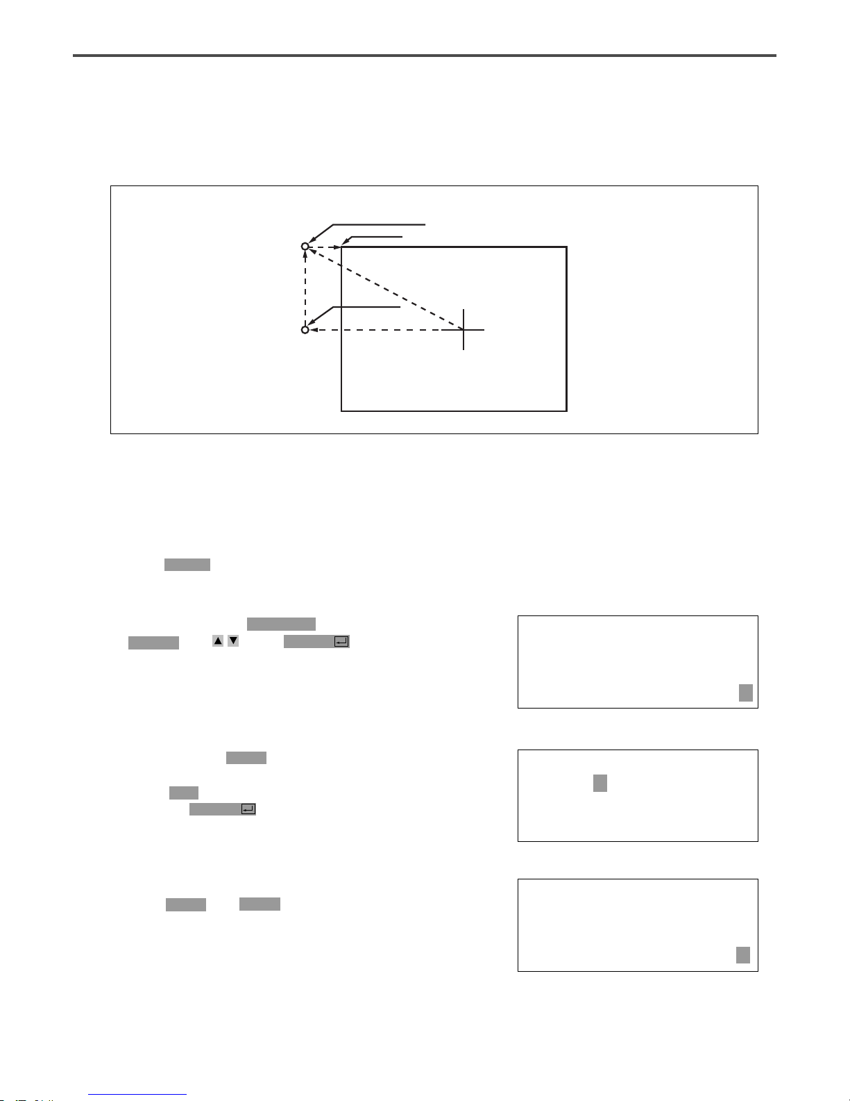
60
A. Insert USB flash drive containing the pattern to
change the 2nd original point.
B. Press MODE key.
C. After moving to “2. Program” menu by using
direction key , press ENTER Key. At this
time, the upper feed plate comes down and
moves to the original point.
ORIGIN
X:00000A N:00000
Y:00000A
Function Code?
3-7) Change/Saving Function of Pattern 2nd Original Point
Change the already setup 2nd original point to new 2nd original point and save it.
New 2nd Original Point
2nd Original Point
Sewing Start Point
Movement
Original Point
014:PTRN READ
NO :001
D. After pressing READ key, input the pattern
number to change the 2nd original point by
using digit key and read in the pattern by
pressing ENTER key. (For example, input
[0][0][1] to read the pattern number 001.)
SEC_ORG NONE
X:-0260A N:00025
Y:00120A
Function Code?
E. Go to the location of 2nd original point by
using FORW and BACK key.
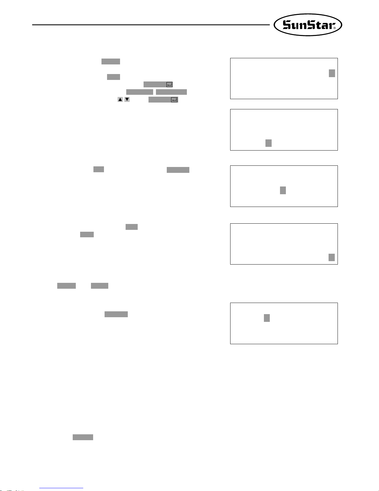
61
<Function Code>
054:MOV 2ndORG<
055:AUTO TRIM
056:SCALE REFER
F. After pressing CODE key, if you know the
function number related to pattern programming,
input three-figure digit number 054 and if you
do not know the number, press ENTER key.
Then, after moving to “054:MOV 2nd ORG”
by using direction key , press ENTER key.
※ X-Y position value may differ according to
the 2nd original point.
054:MOV 2ndORG
X:-0260
Y:00120
N:000
054:MOV 2ndORG
X:-0260
Y:-0050
N:000
G. Move to new 2nd original point by using direction
key.
JUMP
X:-0260A N:00023
Y:-0050A
Function Code?
H. Complete input of new 2nd original point by
pressing EXE key.
I. Confirm if change was made properly by using
FORW and BACK key.
015:PTRN WRITE
NO :008
J. Save the pattern of the changed 2nd original
point by pressing WRITE key.
3-8) Change/Saving Function of Maximum Pattern Sewing Speed and Extension/
Reduction Rate
Set up maximum sewing speed and extension/reduction rate by pattern.
A. Insert floppy diskette containing the pattern to
change maximum sewing speed and extension/
reduction rate.
B. Press MODE key.

62
C. After moving to “2. Program” menu by using
direction key , press ENTER key. At this
time, the upper feed plate comes down and
moves to the original point.
ORIGIN
X:00000A N:00000
Y:00000A
Function Code?
014:PTRN READ
NO :001
D. After pressing READ key, input the pattern
number to change maximum sewing sped and
extension/reduction rate by using digit key and
read in the pattern by pressing ENTER key.
(For example, input [0][0][1] to read the
pattern number 001.)
JUMP
X:-0400A N:00038
Y:00200A
Function Code?
E. Go to pattern data start location by using
FORW and BACK key.
<Function Code>
050:SPD CHNG<
051:STITCH DRAG
052:STITCH DEL
F. After pressing CODE key, if you know the
function number related to pattern programming,
input three-figure digit number 050 and if you
do not know, press ENTER key. Then, after
moving to “050:SPD CHNG”by using direction
key , press ENTER key.
050:SPD CHNG
STSPM:25[100spm]
G. Input maximum sewing speed value STSPM and
press ENTER key.
050:SPD CHNG
STSPM:25[100spm]
XSCAL:100%
H. Input XSCAL, the extension/reduction rate for
X-direction and press ENTER key.
050:SPD CHNG
STSPM:25[100spm]
XSCAL:100%
YSCAL:100%
I. Input YSCAL, the extension/reduction rate for
Y-direction and if you press ENTERkey, all
setting is completed.

63
3-9) Symmetrical Shape Creating Function of Pattern
Make three types of symmetrical shapes for optional point in X and Y axes.
<X-Axis
Symmetry>
<Y-Axis
Symmetry>
<Optional Point
Symmetry>
C. After moving to “2. Program” menu by using
direction key , press ENTER key. At this
time, the upper feed plate comes down and
moves to the original point.
ORIGIN
X:00000A N:00000
Y:00000A
Function Code?
A. Insert USB flash drive containing the pattern to
create symmetrical shape.
B. Press MODE key.
014:PTRN READ
NO :001
D. After pressing READ key, input the pattern
number to create symmetrical shape by using
digit key and read in the pattern by pressing
ENTER key. (For example, input [0][0][1] to
read the pattern number 001.)
CURVE
X:-0060A N:00005
Y:00059A
Function Code?
E. Go to pattern data start location by using
FORW and BACK key.
(Reference) You may place the needle location to create
symmetrical shape in X and Y axes at the optional needle
location to sew. However, symmetry by the optional point
becomes symmetric on the basis of the end point of
sewing data and so you should place needle location at the
end point of sewing data.
015:PTRN READ
NO :009
J. Save the pattern by pressing WRITE key.

64
<Function Code>
043:SYMMETRY X<
044:SYMMETRY Y
045:SYMMETRY P
F. After pressing CODE key, if you know the
function number related to pattern programming,
input three-figure digit number 043 and if you
do not know the number, press ENTER key.
Then, after moving to “043:SYMMETRY X”
by using direction key , press ENTER key.
-X-axis symmetry is Function Code 043
-Y-axis symmetry is Function Code 044
-Optional point symmetry is Function Code 045
CURVE
X:00000A N:00023
Y:00059A
Function Code?
G. Confirm if symmetrical shape was made properly
by using FORW and BACK key.
3-10) Condensed Sewing Stitch Inserting Function
It is the function to prevent stitches from being untangled by making stitch width condensed in sewing
start part and sewing end part of pattern data.
A. Insert USB flash drive containing the pattern to
insert condensed sewing stitch.
B. Press MODE key.
Initial Condensed Sewing 3 stitches
Sewing Start Point
Sewing End Point
Sewing Start Point
Sewing End Point
Initial Condensed Sewing
End Condensed Sewing 3 Stitches End Condensed Sewing
3.0mm 0.5mm
3.0mm 0.5mm
< Before Condensed Sewing Insertion > < After Condensed Sewing Insertion >
C. After moving to “2. Program” menu by using
direction key , press ENTER key. At this
time, the upper feed plate comes down and
moves to the original point.
ORIGIN
X:00000A N:00000
Y:00000A
Function Code?

65
014:PTRN READ
NO :001
D. After pressing READ key, input the pattern
number to insert condensed sewing stitch by
using digit key and read in the pattern by
pressing ENTER ey. (For example, input
[0][0][1] to read the pattern number 001.)
CURVE
X:-0060A N:00040
Y:00039A
Function Code?
E. Go to pattern data end location by using
FORW and BACK key.
<Function Code>
041:CNDNS STI<
042:OVLAP STI
043:SYMMETRY X
F. After pressing CODE key, if you know the
function number related to pattern programming,
input three-figure digit number 041 and if you
do not know the number, press ENTER key.
Then, after moving to “041:CONDNS STI” by
using direction key , press ENTER key.
041:CNDNS STI
SNUM:4[STITCH]
G. After inputting the number of initial condensed
sewing stitch(1~9 stitch), press ENTER Key.
041:CNDNS STI
SNUM:4[STITCH]
ENUM:4[STITCH]
H. After inputting the number of final condensed
sewing stitch(1~9 stitch), press ENTER key.
041:CNDNS STI
SNUM:3[STITCH]
ENUM:3[STITCH]
WIDTH:010[0.1mm]
I. After inputting condensed stitch width, if you
press EXE or ENTER Key, input of
condensed sewing stitch is completed.
※ The stitch width of the number of stitches set
up at sewing start point(the number of initial
condensed sewing stitch) and sewing end
point(the number of end condensed sewing stitch)
is changed into condensed stitch sixth.
LINE
X:-0160A N:00080
Y:00039A
Function Code?
J. Confirm if the number of condensed sewing
stitch was made properly by using FORW and
BACK key.

66
3-11) Automatic Back Tack(B/T) Inserting Function
You can apply automatic back tack inserting function for several pattern.
A. Insert USB flash drive containing the pattern to
insert automatic back tack.
B. Press MODE key.
Initial BackTack
End BackTack
Initial BackTack
End BackTack
C. After moving to “2. Program” menu by using
direction key , press ENTER key. At this
time, the upper feed plate comes down and
moves to the original point.
ORIGIN
X:00000A N:00000
Y:00000A
Function Code?
014:PTRN READ
NO :001
D. After pressing READ key, input the pattern
number to insert automatic back tack by using
digit key and read in the pattern by pressing
ENTER key. (For example, input [0][0][1] to
read the pattern number 001.)
LINE
X:-0160A N:00040
Y:00039A
Function Code?
E. Go to the location that pattern data ends by
using FORW and BACK key.
Origin Point of Machine

67
<Function Code>
040:BACK TACK<
041:CNDNS STI
042:OVLAP STI
F. After pressing CODE key, if you know the
function number related to pattern programming,
input three-figure digit number 040 and if you
do not know the number, press ENTER key.
Then, after moving to “040:BACK TACK” by
using direction key , press ENTER key.
040:BACK TACK
BTNUM:4[STITCH]
G. Input the number of back tack to insert and
press ENTER key.
040:BACK TACK
BTNUM:4[STITCH]
BTMOD:0[0/1]
H. Input back tack mode. Press ENTE key.
Mode Type
Mode 0:
Mode 1:
LINE
X:-0160A N:00040
Y:00039A
Function Code?
I. Confirm if back tack was made properly by
using FORW and BACK key.
3-12) OverLap Sewing Stitch Inserting Function
You can apply automatic overlap sewing stitch inserting function for several patterns.
OverLap function can apply to the pattern design of closed roof that start point and end point meet.
Except, though it is not closed roof type of pattern and start point and end point have 1mm of distance,
OverLap function can use.
Be able to select a maximum of 20 stitch.
5 Stitch OverLap
5 Stitch OverLap
Origin Point of Machine

68
A. Insert USB flash drive containing the pattern to
insert overlap sewing stitch.
B. Press MODE key.
C. After moving to “2. Program” menu by using
direction key , press ENTER key. At this
time, the upper feed plate comes down and
moves to the original point.
ORIGIN
X:00000A N:00000
Y:00000A
Function Code?
014:PTRN READ
NO :001
D. After pressing READ key, input the pattern
number to insert overlap sewing stitch by using
digit key and read in the pattern by pressing
ENTER key. (For example, input [0][0][1] to
read the pattern number 001.)
CIRCLE
X:00000A N:00030
Y:00100A
Function Code?
E. Go to the location that pattern data ends in
order to apply overlap function by using FORW
and BACK key.
<Function Code>
042:OVLAP STI<
043:SYMMETRY X
044:SYMMETRY Y
F. After pressing CODE key, if you know the
function number related to pattern programming,
input three-figure digit number 042 and if you
do not know the number, press ENTER key.
Then, after moving to “042:OVLAP STI” by
using direction key , press ENTER key.
042:OVLAP STI
OVNUM:4[STITCH]
G. Input the number of overlap stitch to insert and
press ENTER key.
CIRCLE
X:-0092A N:00034
Y:00037A
Function Code?
H. Confirm if back tack was made properly by
using FORW and BACK key.
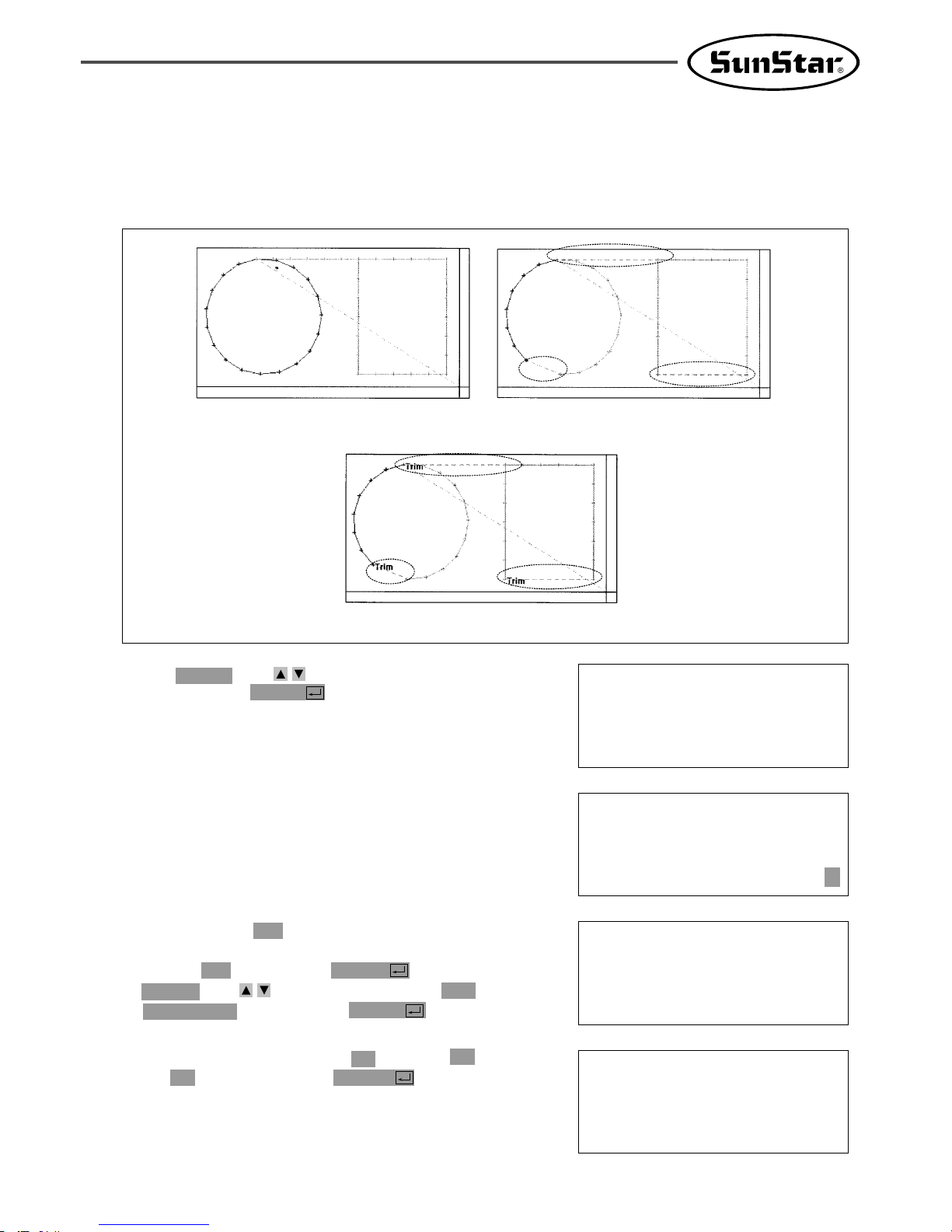
69
C. If the function code No. related to the pattern
programming were known, enter three digits of
number, 055. If not, press ENTER and use
direction key to move the cursor on “055:
AUTO TRIM”, and then press ENTER .
ORIGIN NONE
X:00000A N:00000
Y:00000A
Function Code?
<< Main Menu >>
2. Program
3. Bobbin Wind
4. Machine Test
3-13) Automatic Insertion of Thread Trimmer Code when Deleting Stitches
If the user deletes any section of pattern or the stitches, the user can define whether to insert thread
trimmer code on the related location.
A. Use direction key to select “2. Program”,
and then press ENTER .
B. Press code key again on the Operation Box.
D. On the following screen, press “1”to change “0”
to “1”, and then press ENTER to set
automatic thread trimmer function.
<Function Code>
CODE NO :055
055:AUTO TRIM
TRIM:1[0/1]
< Pattern Design >
< Deleted Stitches or Pattern (Before Setting-Up
Automatic Insertion of Thread Trimmer >
< After Setting-Up Automatic Insertion of Thread Trimmer >

70
3-14) Setting-Up Reference Point for Zooming
On the sewing mode, the user can zoom design based on machine origin, second origin, sewing starting
point or user-defined reference point. However, the second origin and user-defined reference point must be
set in the pattern design before zooming based on those reference points.
E. When deleting stitches or pattern, the user can
confirm the automatic insertion of thread
trimmer by either making new design or
retrieving the existing design saved in a USB flash
drive. Please refer to “2-3) Delete Number of
Stitches”and “2-4) Partially Delete Pattern Data”.
ORIGIN NONE
X:00000A N:00000
Y:00000A
Function Code?
<< Main Menu >>
1. Parameter Set
2. Program
3. Bobbin Wind
A. Press MODE.
B. Use direction key to select “1. Parameter
Set”menu.
<Parameter Set>
PARA No :076
C. Press ENTER to open a screen shown on
the right. Input [0][7][6] and press ENTER
to move onto the 076. Scale Refer item.
076. Scale Refer
1) MACHINE_ORG
2) SECOND_ORG
3) SEWING_STR
4) REFER_PNT
D. The following four items of zooming reference
point are displayed.
By default, it is set on MACHINE_ORG. Use
direction key to select the item desired, and
then press ENTER to set.
Descriptions of each item are as follows:
MACHINE_ORG : Zooming based on the machine origin.
SECOND_ORG : Zooming based on the second origin.
SEWING_STR : Zooming based on the sewing starting point.
REFER_PNT : Zooming based on the point defined by user at program code No. 076 of Function
Code.

71
E. Setting-Up Reference Point for Punching.
F. After setting-up the reference point item and the reference point, store the decided design into USB
flash drive, press ESC to return to the sewing mode, and then apply the scale desired.
The following illustration shows the zooming functions for each reference point item.
<Function Code>
Code No :076
① After creating any pattern design, use
back/forth stitch function to move it to the
reference point to be set, and then press code
key.
② Input 076 for the code No., and press
ENTER .
SCALE REFER NONE
X:-0300A N:00097
Y:-0300A
Function Code?
③ On the following SCALE REFER item, use
back/forth stitch function to confirm whether
the reference point would be inserted.
Sewing Start
MACHINE_ORG
SECOND_ORG
Sewing Start
2. Origin
2. Origin
New Sewing Start
New Sewing Start

72
Sewing Start
SEWING_START
REFER_PNT
Sewing Start
Reference Point
Reference Point
New Sewing Start
New Sewing Start
C. After moving to “6. EMB Call”by using direction
key , press ENTER key.
<< Main Menu >>
6. EMB Call
<< Main Menu >>
0. Initialize
1. Parameter Set
2. Program
3-15) Embroidery Design Call Function
It means the function converting to sew by calling SunStar’s “.SST Sewing Design File”and TAJIMA’s
“.DST Sewing Design File”.
A. Insert the USB flash drive stored embroidery
designs into the USB terminal.
B. Press MODE key.
D. The next screen appears and READY LED
light of operation box flickers. Select TAJIMA
sewing design by pressing Number 1 key.
Insert Disk
SWF(0)/TAJIMA(1)
To Exit (ESC)...
E. The next screen appears again. (Current screen
can be difference according to sewing design in
the diskette.) After selecting the design to
convert by using direction key, press ENTER
key.
<< FILE LIST >>
G013.dst <

73
I. Return to initial sewing screen by pressing ESC
key. (The screen in the next can be different
according to sewing design type, user’s working
order and environment.
NO:000 NOR_SEW
XS:100%
YS:100% SP:2500
BC:058 PC:0058
J. After inputting pattern file number saved in the
front by pressing No. key button on the
operation box, call the design by pressing
ENTER key.
NO:001 NOR_SEW
XS:100%
YS:100% SP:2500
BC:058 PC:0058
K. Fasten the working material by pressing foot
plate of right pedal and start sewing by
stepping start pedal.
F. Then screen changes again and input the design
number by using digit key to save into pattern
file. And press ENTER key.
Enter Number to
be stored
NO :001
G. Read the USB flash drive while blinking the
READY LED of the operation box continuously.
H. If you converted and read sewing design into
pattern file, the next screen appears.
<< Main Menu >>
6. EMB Call
3-16) JUKI Design Call
The function of converting JUKI's AMS-Series design files was added.
A. Select No. 7 “OtherPtrnCall" from the main menu.
Insert USB
JUKI/Press(0)
To Exit(ESC)...
<< Main Menu >>
7. OtherPtrnCall <
B. Insert a USB flash drive and press the No.0
key.
<< FILE List >>
100.M3 <
200.M3
300.M3
C. The list of JUKI files saved in the USB flash
drive shows up on the screen.
Move the cursor to the conversion target file,
and press “Enter."
74
3-17) Sewing Limit Function
This function for setting sewing limit is designed to expand the mechanical sewing limit of the machine.
First mechanically expand the X-Y feeding area of the machine, and set the sewing limit in the parameter
in accordance with the expanded area.
※In case of C-Series, the area can be expanded up to 25000×25000mm.
<< Main Menu >>
1. Parameter Set
2. Program
3. Bobbin Wind
A. Press MODE and select Parameter Set in Main
Menu.
Refer to the following for set-up.
< Parameter Set >
078. Sewing Limit
079. XPLUS Limit
080. XMINUS Limit
078.Sewing Limit
1) DISABLE <
2) ENABLE
B. Use the direction change cursor in the
Parameter Set and select 078. Sewing Limit.
C. Sewing Limit is defaulted at 1) DISABLE.
<< Main Menu >>
7. OtherPtrnCall <
E. When conversion is finished, the screen returns
to the original status.
<< Main Menu >>
5. Pattern List <
6. EMB Call
7. OtherPtrnCall
F. Press No. 5 “Pattern List" from the main
menu, and check whether the converted file
from the USB flash drive is properly saved.
Memory(0)/USB(1)
To Exit(ESC)...
G. Press No. 1.
<< Pattern List >>
001 <
H. The list of design patterns saved is displayed.
Enter Number to
be stored
NO:001
D. Enter a new name for the file, which will be
converted and saved, and press “Enter."

75
< Parameter Set >
079. XPLUS Limit
080. XMINUS Limit
081. YPLUS Limit
078.Sewing Limit
1) DISABLE
2) ENABLE <
079. XPLUS Limit
X:00065
D. Use the direction change cursor to select
2) ENABLE and press ENTER .
E. Use the direction change cursor to select
079. XPLUS Limit.
The default value is set at 65mm (for SPS-1306
machines). Use the up/down direction key
to increase the limit as desired.
※ In case of C-Series, the unit can be set by the
unit of [50mm]. As such, in case of 5050, it is
displayed as X : 00050. In other words,
50×50[mm] equals 2500mm. Likewise, if the
maximum expansion is X: 00250,
it means 250×50[mm]=12500mm.
※ Ex) If you increase the X-axis mechanical
feeding limit to a maximum 140mm, you can
set up to 70mm in the X-axis plus direction.
079. XPLUS Limit
X:00070
F. To increase limit in the opposite direction, select
080. XMINUS Limit.
The default value is set at -65mm (for SPS1306 machines). Use the up/down direction
key to increase the limit as desired.
※ Ex) If you increase the X-axis mechanical
feeding limit to a maximum 140mm, you can
set up to -70mm in the X-axis minus
direction.
< Parameter Set >
080. XMINUS Limit
081. YPLUS Limit
082. YMINUS Limit
080. XMINUS Limit
X:-00065
080. XMINUS Limit
X:-00070
G. If you increased the mechanical feeding limit of Y-axis, refer to the above instructions to expand the
feeding limit.
After setting the sewing limit in accordance with the mechanically expanded limit, you can check if the
machine feeds to the actual expanded limit. Use the X-Y Jog Test function in Machine Test function
to check whether the machine feeds to the actual expanded limit.
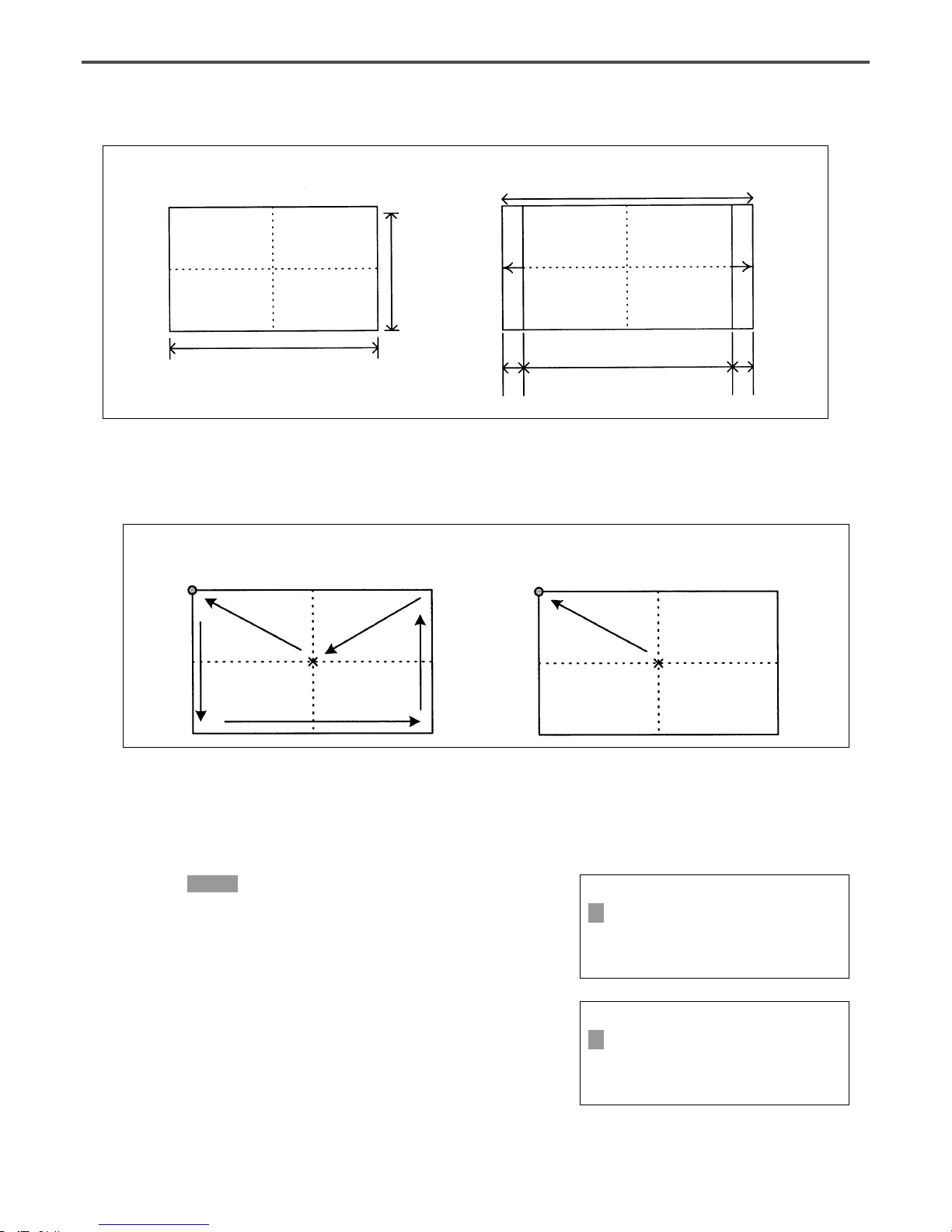
76
Caution) The sewing limit function is always defaulted at DISABLE and the sewing limit is set at the
standard size for each type at the factory.
3-18) Quick Origin Search Motion Function for 1811 Machines
< Before > < After >
As SPS-1811 machines is equipped with reverse devices, origin search motion is performed as shown in the
Before picture and feeds back to the starting point of sewing. However, if there is no reverse device,
search motion takes place very slowly. This quick origin search motion function ensures fast origin search
as shown in the After picture and feeding back to the starting point of sewing.
Starting point of sewing
Origin Origin
Starting point of sewing
130mm
< Before > < After >
60mm
X-axis expanded limit
130mm
140mm
5mm 5mm
<< Main Menu >>
1. Parameter Set
2. Program
3. Bobbin Wind
A. Press MODE to select Parameter Set in Main
Menu.
Refer to the following for set-up.
< Parameter Set >
083. FFOrign 1811
084.
AFC Down Time
085. AFC Up Time
B. Use the direction change cursor in Parameter
Set and select 083. FFOrign 1811.
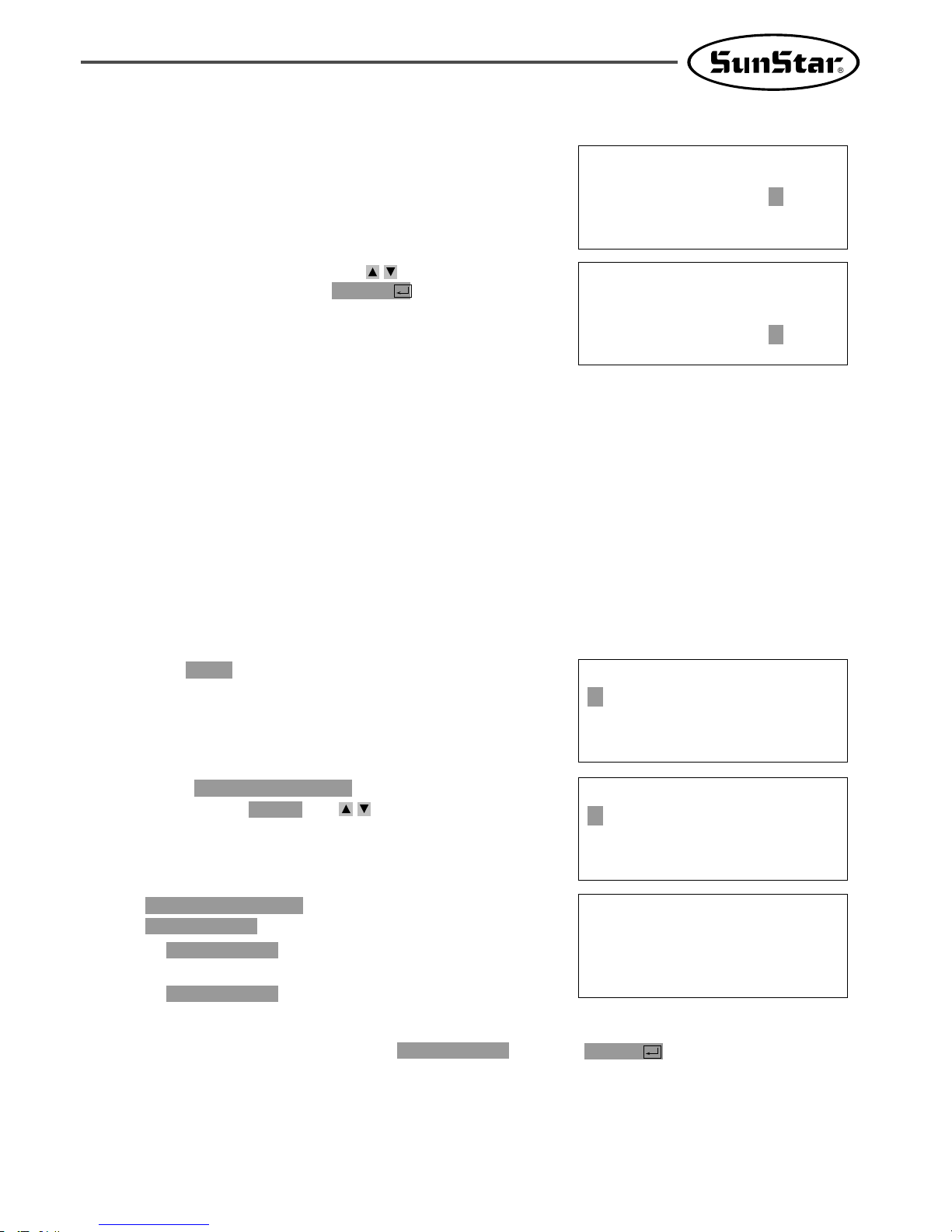
77
C. is originally set at
.
1) : After completion of sewing,
origin search motion gets deleted.
2) : After completion of sewing,
origin search motion gets set.
2)JOB_READY
1)JOB_SETUP
2)JOB_READY
084. HOOKORG MODE
084.HOOKORG MODE
1) JOB_SETUP
2) JOB_READY <
D. Deleting origin search motion move to and press key.
ENTER
1)JOB_SETUP
3-19) Setting Origin Search Function of Upper and Lower Shafts after Finishing
Sewing [only applied for SPS/C-Series]
How to set origin search motion of upper and lower shafts (hook timing) is described below. Upper and
lower shafts of SPS/5050 Series are separated with each other, operating independently, which means that
hook timing by the operation of both shafts is important. If the timing becomes improperly set during
operation or trimming process, this function can always guarantee the proper hook timing by resetting it
through origin search motion of upper and lower shafts after completion of sewing.
How to set origin search function of upper and lower shaft.
<< Main Menu >>
1. Parameter Set
2. Program
3. Bobbin Wind
A. Press key and select Parameter Set from
Main Menu.
MODE
< Parameter Set >
084. HOOKORG MODE
085. HEAD En/Dis
086. RevAfterTrim
B. Select from Parameter
Set by pressing keys .
direction
084. HOOKORG MODE
C. FFOrign 1811 is defaulted at 1) DISABLE.
This setting ensures slow origin search motion
all the time.
083.FFOrign 1811
1) DISABLE <
2) ENABLE
083.FFOrign 1811
1) DISABLE
2) ENABLE <
D. Use the direction change button to select
2) ENABLE and press ENTER . This
setting ensures fast origin search motion all the
time.

78
3-20) Setting Machine Head up or Down Function [only for SPS/C-Series]
How to set machine Head up or down function is described below. Vertical control of Head is easy,
because Head of SPS/C-Series is connected with air pressure cylinder. Parameter is originally set not to
raise machine Head after completion of sewing. However, change in setting will raise machine Head after
completion of sewing. This function is available, depending on material and operating environment.
How to set machine Head up or down function:
<< Main Menu >>
1. Parameter Set
2. Program
3. Bobbin Wind
A. Choose Parameter Set from Main Menu by pushing
.
MODE
C. When choosing, is set at
.
: After finishing sewing, leave the
Head of machine down.
: After finishing sewing, leave the
Head of machine up.
2)ENABLE
1)DISABLE
1)DISABLE
085. HEAD En/Dis
085.HEAD En/Dis
1) DISABLE
2) ENABLE <-
D. To up the Head, move to , and then key.
ENTER
2)ENABLE
< Parameter Set >
085. HEAD En/Dis
086. RevAfterTrim
087. ReverseAngle
B. Choose from Parameter Set
by using keys .
direction
085. HEAD En/Dis
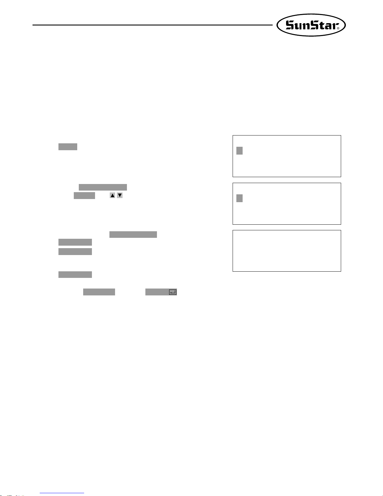
79
D. Move to and press key in order to use this function
ENTER2)ENABLE
C. When choosing, is set at
.
: After trimming, don’t use the
reverse rotation function after
trimming.
: After trimming, use the reverse
2)ENABLE
1)DISABLE
1)DISABLE
086. RevAfterTrim
086.RevAfterTrim
1) DISABLE
2) ENABLE <
3-21) Setting Reverse Rotation after Trimming [Only applied for SPS/B/C-Series]
Function of Reverse rotation after trimming is as follows. When sewing material is thick, the thick material
can interfere with needle if the needle is placed at the highest point of thread take-up. In that case, the
interference will be prevented if the needle is placed in reverse order. Therefore, after trimming, set the
point of reverse rotation as the applicable angle by using the reverse rotation function. If sewing material is
not thick, don’t use the function.
Setting method is as follows.
<< Main Menu >>
1. Parameter Set
2. Program
3. Bobbin Wind
A. Choose Parameter Set from Main Menu by pushing
key.
MODE
< Parameter Set >
086. RevAfterTrim
087. ReverseAngle
088. Oil Control
B. Choose from Parameter Set by
using keys .
direction
086. RevAfterTrim

80
D. Press key to save the reset angle.
ENTER
C. is originally set at .
The angle can be reset from .
Angle can be reset by pressing keys
on the OP box.
direction
1 to 40[degree]
15[degree]087. ReverseAngle
087.ReverseAngle
15[degree]
087.ReverseAngle
40[degree]
3-22) Setting the Angle of Reverse Rotation after Trimming [only applied for SPS/B/C-Series]
How to set the angle of reverse rotation, after trimming, is described below.
This function is available only when post-trimming reverse rotation function of mentioned
above is set at .
Enable
076. RevAfterTrim
Setting method is as follows.
<< Main Menu >>
1. Parameter Set
2. Program
3. Bobbin Wind
A. Press key and choose Parameter Set from
Main Menu.
MODE
< Parameter Set >
087. ReverseAngle
088. Oil Control
089. OillOffTime
B. Choose from Parameter Set by
pressing keys .
direction
087. ReverseAngle
[Post-trimming Reverse Rotation Function Setting In Case Of SPS/A-Series Belt-type Machine]
Fortuna S-II P/U
MD 8Pin
Connector
Encoder
1. Turn off the power and connect with Fortuna S-II P/U.
2. Turn on the power while pressing the Prog button of P/U.
3. Wait until the beep sound is heard.
4. Move the A-Group parameter by pressing the A button and the Prog button of
P/U at the same time.
5. Move to A-Group #60 by pressing the N2 button (to determine whether to use
the post-trimming reverse rotation function)
6. Press the C button to change the value from “0”to “1”.
7. Press the ENTER button to save the setting.
8. Press the N2 button again to go to A-Group #61 (to determine the volume of
post-trimming reverse rotation)
9. Press the C button to set the volume of post-trimming reverse rotation. The
maximum volume is 40.
10. Press the ENTER button to save the setting.
11. Press the Prog button to end the parameter setting.
12. Turn the power off and remove the cable.
13. Then, after trimming, the reverse rotation function will be applied according to
the set value.
※ For more information, see the Fortuna S-II P/U manual.

81
3-23) Setting Output Port [Only applied for SPS/C-Series]
The function is that a user can program devices that are set to certain places when punching. The list of
the devises is as follows.
NO Device
Content
00 PF Presser Feet
01 FF Feed Plate
02 TT Trimming
03 TH Thread Holder
04 WP Wiper
05 FF_L Left Feed Plate
06 TWO_STG Two-Step Stroke Feed Plate
07 REV_DEV Inverting Device
08 REAR_FF Rear Feed Plate
09 TR Thread Release
10 AFC Material Conveying Pressing Device
11 TR3 Thread Release 3
12 HEAD Machine Head
13 OP55~OP57 Other Ports [Don’t use]
14 OP60~OP67 Other Ports [Don’t use]
Line 1
Line 3
Line 4
TR3 : ON
Line 2
TR3 : OFF

82
The process of program to operate in specific range of general square pattern is as
follows.
thread control device 3
D. Pressing key will move feed plate according
to the computed data after computing pattern
data.
EXE
C. Press key and move to the original position
of the square by pressing keys .
And then press key.
PNT.SET
direction
JUMP
004:JUMP
X:-0650
Y:00300
N:001
JUMP NONE
X:-0650A N:00065
Y:00300A
Function Code?
E. Press key, input stitch width by pressing
number keys and then press key.
(Ex. Press to set stitch width at 3mm.)
[0][3][0]
ENTER
LINE
007:LINE
WIDTH:030[0.1mm]
F. Move to the first point position of LINE by
pressing keys .
Press key.
PNT.SET
direction
007:LINE
X:00650
Y:00300
N:001
G. Register the first point position of square by
pressing key. After computing pattern data,
feed plate will move according to the computed
data.
EXE
LINE NONE
X:00650A N:00104
Y:00300A
Function Code?
<< Main Menu >>
2. Program
3. Bobbin Wind
4. Machine Test
A. Press key.
MODE
ORIGIN
X:00000A N:00000
Y:00000A
Function Code?
B. Move to “2. Program”by pressing keys
and press key.
Upper feed plate will come down and move to
original point.
ENTER
direction

83
K. Return to the initial screen. To create ,
input switch width by using Line key.
Second Line
J. Pressing key shows the following
screen. Move to ON and then press
key.
At the same time, the is
programmed at the end of the .
created Line
thread control device 3
ENTER
ENTER
057:SET OP
TR3 :OFF
ON <
TR3 ON NONE
X:00650A N:00105
Y:00300A
Function Code?
L. Press key and then resister
by using key.
After computing pattern data, feed plate moves
according to the data.
EXE
Second Line
PNT.SET
LINE NONE
X:00650A N:00125
Y:-0300A
Function Code?
M. To program , press key. Function is
57. If the code number is not identified, press
key to indicate function code list and
move to by using keys
.
direction57 SET OP
ENTER
CODETR3
<Function Code>
057:SET OP <
058:CHK IP
059:TIME DELAY
N. Move to in the SET OP function
list by using key. Press
key.
ENTERENTER
number 11 TR3
057:SET OP
11:TR3 <
12:HEAD
13:OP55
<Function Code>
057:SET OP <
058:CHK IP
059:TIME DELAY
H. Press key to program
Function code is . If function code
number is not identified, press key to
see function code list and then move to
by pressing keys
.
direction
number 057 SET OP
ENTER
number 057
Release 3)
TR3(ThreadCODE
057:SET OP
11:TR3 <
12:HEAD
13:OP55
I. Move to in SET OP functions
list by pressing key. Press
key.
ENTERENTER
number 11 TR3

84
R. If there is no problem with sewing, press key again, and then press key to save design.
WRITE
TEST
Q. Create third and as the way the first and second lines are created. And then press TEST to check
whether is operating or not.
in the . TR3 will be at at the beginning of the and OFF
at the .
end of the second LINE
second LINEONfirst LINETR3 is set at OFF
TR3
fourth line
057:SET OP
TR3:OFF <
ON
O. Pressing key shows the following
screen. To delete the set , go to and
then press key. At the same time,
the is programmed at
the end of the created Line.
thread control device 3
ENTER
OFFTR3
ENTER
TR3 OFF NONE
X:00650A N:00126
Y:-0300A
Function Code?
P. Return to the initial screen.
3-24) Setting Time Delay when Output Port is Being Used [only applied for SPS/C-Series]
The function is to program applicable time delay when output port is being used.
The program will be explained later in .
J. of 3-23) Setting Output Port
057:SET OP
TR3:OFF
ON <
A. Pressing key will show following page.
Move to ON and press key. At the
same time, will be
programmed at the end of the created line.
thread control device 3
ENTER
ENTER
TR3 ON NONE
X:00650A N:00105
Y:00300A
Function Code?
B. Return to the initial page of program.
Program before creating second LINE.
Time Delay
C. Press key to program .
Function code is number 58. If function code number is
not identified, press key to see function
code list and then move to number
by pressing keys .
direction
059 TIME DELAY
ENTER
Time Delay
CODE
<Function Code>
059:TIME DELAY <
060:SET TR3
000:TRIM

85
D. Press key to set Time Delay.
.
. Set desired Time delay
by using number keys. Input . If 50[ms] is
input, the real Time Delay is .
200[ms]
50[ms]
Time delay unit is 4[ms]
Time Delay is originally set at 0[ms]
ENTER
059:TIME DELAY
DELAY:0050[x4ms]
E. Return to the initial screen.
To create Second Line, input switch width by
using Line key.
TIME DELAY NONE
X:00650A N:00106
Y:00300A
Function Code?
F. After pressing key, register Second Line
by using .
After computing pattern data, feed plate moves
according to the data.
EXE
PNT.SET
LINE NONE
X:00650A N:00126
Y:-0300A
Function Code?
G. The rest part is the same with .
L~R in 3-23) Output Port Setting Function
So, when time delay is programmed, will operate shortly before second Line sewing following first Line
sewing. And the operation will discontinue for shortly before sewing and then second Line sewing will
start. By doing so, a user can set delay time at each designated device and take motion when operating
device related output port.
200[ms]
TR3
3-25) 3rd Thread Adjusting Device (TR3) Setting
This function allows users to make additional adjustment of the upper thread tension for a certain section.
Line 1
Line 3
Line 4
TR3 : ON
Line 2
TR3 : OFF

86
<Function Code>
063:SET TR3 <
H. Press key to program
The concerned function code is 063. If you want
to search it from the function code list, press
and move to with
direction keys .
063 SET TR3
ENTER
Release 3)
TR3(ThreadCODE
D. Pressing key will move feed plate according
to the computed data after computing pattern
data.
EXE
C. Press key and move to the original position
of the square by pressing keys .
And then press key.
PNT.SET
direction
JUMP
004:JUMP
X:-0650
Y:00300
N:001
JUMP NONE
X:-0650A N:00065
Y:00300A
Function Code?
E. Press key, input stitch width by pressing
number keys and then press key.
(Ex. Press to set stitch width at 3mm.)
[0][3][0]
ENTER
LINE
007:LINE
WIDTH:030[0.1mm]
F. Move to the first point position of LINE by
pressing keys .
Press key.
PNT.SET
direction
007:LINE
X:00650
Y:00300
N:001
G. Register the first point position of square by
pressing key. After computing pattern data,
feed plate will move according to the computed
data.
EXE
LINE NONE
X:00650A N:00104
Y:00300A
Function Code?
<< Main Menu >>
2. Program
3. Bobbin Wind
4. Machine Test
A. Press key.
MODE
ORIGIN
X:00000A N:00000
Y:00000A
Function Code?
B. Move to “2. Program”by pressing keys
and press key.
Upper feed plate will come down and move to
original point.
ENTER
direction

87
J. Return to the initial screen. To create ,
input switch width by using Line key.
Second Line
I. When is pressed, the following screen
appears. Move the cursor to ON and press
. Upon striking ,
code is created at
.
the line
the end of line adjuster
the 3rd
ENTERENTER
ENTER
063:SET TR3
TR3 :OFF
ON <
TR3 ON NONE
X:00650A N:00105
Y:00300A
Function Code?
K. Press key and then resister
by using key.
The feed plate moves to the set position in
accordance with the data calculation result.
EXE
Second Line
PNT.SET
LINE NONE
X:00650A N:00125
Y:-0300A
Function Code?
L. To program , press key. Function is
63. The concerned function code is 063. If you
want to search it from the function code list,
press and move to
with direction keys .
063 SET TR3
ENTER
CODETR3
<Function Code>
063:SET TR3 <
063:SET TR3
TR3:OFF <
ON
M. When is pressed, the following screen
appears. To cancel the setting, move the
cursor to and press . At the
same time, the is
programmed at the end of the created Line.
thread control device 3
ENTEROFF
TR3
ENTER
TR3 OFF NONE
X:00650A N:00126
Y:-0300A
Function Code?
N. Return to the initial screen.
P. If there is no problem with sewing, press key again, and then press key to save design.
WRITE
TEST
O. Create third and as the way the first and second lines are created. And then press TEST to check
whether is operating or not.
in the . TR3 will be at at the beginning of the and OFF
at the .
end of the second LINE
second LINEONfirst LINETR3 is set at OFF
TR3
fourth line

88
3-26) Basic Clamp Position Setting
※This function is to set the basic position of the clamp. When parameters need to be changed, clamp’s
pneumatic lines shall be exchanged in accordance with conditions.
A and B
<< Main Menu >>
1. Parameter Set <-
2. Program
3. Bobbin Wind
A. Select .
Parameter Set
104 : Clmp Ref POS
1)Ref_UP
<-
2)Ref_DOWN
B. To change the basic position of the clamp to
, go to Parameter and
select .
(Default is .)
1) Ref_UP
2)Ref_DOWN
104. Clmp Ref POS
Down
※ Key Points
1. If the value of is changed to , the two pneumatic tubes connected to the
clamp shall be exchanged.
Ref_DOWN104.Clmp Ref POS

89
A. Press MODE key.
B. By using direction keys , move to “5.
Program List”menu.
C. If you press ENTER key, the screen of the
right sides appears. To check the pattern
number in inner memory, press digit key, 0, and
to check the pattern number in a USB flash
drive, press digit key, 1
D. If you press digit key, 1. the pattern number
in a USB flash drive is shown.
E. If a pattern number is not indicated on one
screen, check it by using direction key , with
moving forward and downward.
<< Main Menu >>
5.Pattern List
6.EMB CALL
Memory(0)/USB(1)
To Exit(ESC)...
<<Pattern List>>
002 <003
004
4-1) Checking and Deleting the Pattern Number
It is used to check or delete the pattern number in USB flash drive and inner memory.
4) Pattern Data General Function
<<Pattern List>>
004 <005
006
F. After moving to the pattern number that you
want to delete by using direction keys , if
you press PTN DEL key, the screen of the
right side appears. To delete the pattern, press
ENTER key, and to cancel, press ESC key.
G. By pressing ESC key, complete the check of
pattern number. By pressing ESC key, back to
the initial screen.
Are YOU Sure?
Y(ENTER)/N(ESC)

90
A. Insert a USB flash drive that you want to
make a copy.
B. Press MODE key.
C. By using direction keys , move to “2.
Program”menu, then press ENTER key.
At this time the upper feed plate descends, and
moves to the origin.
D. After pressing READ key, input the pattern
number that is to be copied by using digit keys.
(For example, to make a copy “001”, input [0]
[0][1].)
<< Main Menu >>
2. Program
3. Bobbin Wind
4. Machine Test
ORIGIN
X:00000A N:00000
Y:00000A
Function Code?
014:PTRN READ
NO :001
4-2) Making a Copy the Pattern to Another Number or Diskette
It is used to make a copy the pattern to another number or USB flash drive. It is available to check,
make a copy or delete the pattern number.
No. 1 USB
flash drive
No.001
No. 2 USB
flash drive
Make a copy the pattern to the
same USB flash drive as another
pattern number.
Make a copy the pattern to
another USB flash drive as same
pattern number or different one.
No.001
No.002
E. Press ENTER key. The READY LED flickers
during reading the pattern data.
ORIGIN
X:00000A N:00000
Y:00000A
Function Code?

91
F. After the READY LED turns off, if you want
to make a copy the pattern to the same USB
flash drive as another pattern number, press
WRITE key and input the pattern number that
is to be copied by using digit keys.
(For example, input [0][0][2] to make a copy
as“002”.)
In case of copying to another UBS flash drive,
insert another USB flash drive after pulling out
the original USB flash drive and press the
WRITE copy as number key.
(For example, input [0][0][1] to make a copy
as“001”.)
G. After leaving the programming menu by pressing
MODE key, back to the initial screen by
pressing ESC key.
※ Referring to “Pattern Number Check”, check
the copied pattern number.
015:PTRN WRITE
NO :002
<< Main Menu >>
2. Program
3. Bobbin Wind
4. Machine Test
4-3) Function to copy saved patternS from interior memory to USB flash drive
This function is designed to summon pattern design data stored in CPU memory and store it in the USB
flash drive while the machine is in sewing mode. In the past, users themselves punched designs in the
program mode and stored in USB flash drive, but could not call design data in CPU memory and store
them in USB flash drive during sewing mode.
Refer to the following for set-up.
A. To store design, the machine has to be in the
sewing mode.
B. While the machine is in the sewing mode, key
in the desired pattern design number and press
ENTER .
C. If the machine is in the sewing mode, a light
will come up in Ready LED located at the
upper left corner.
D. Press ENTER again. The sewing mode will be
turned off and the light will go off in Ready LED.
E. By following the step A, B, C, D only once,
stored designs in CPU memory can be stored in
USB flash drive.
F. Insert a USB flash drive into the USB terminal
and press the “Save”key on the lower left OP
Box.
G. In the LCD display of the OP Box, the sewing
mode will be changed to storing mode.
H. Key in desired design number and press
ENTER to store design in the USB flash
drive.
Ready LED
Write Key
015.PTRN WRITE
NO :100
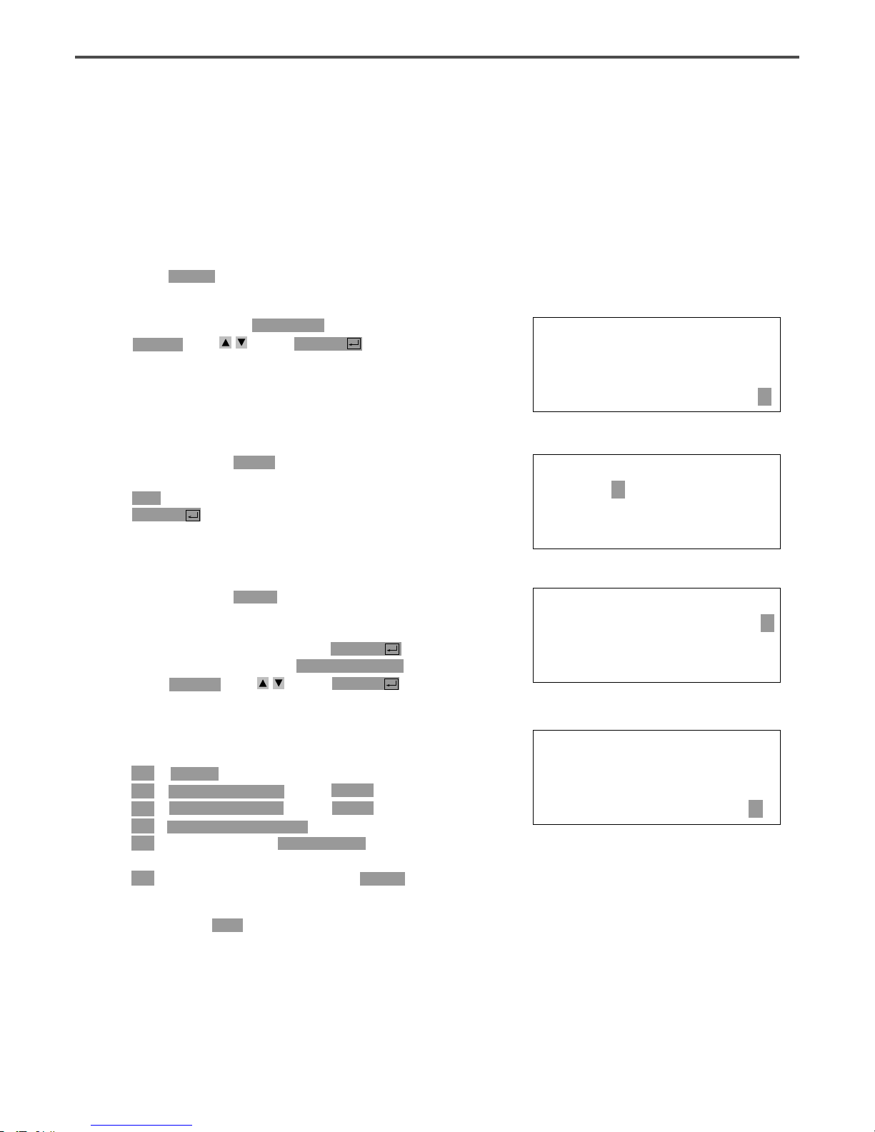
92
F. The meaning of information being displayed on
the screen is as follows:
NO - Pattern number
XS - Extension/reduction rate of X-axis direction.
YS - Extension/reduction rate of Y-axis direction.
SP - Maximum sewing speed
RV - Whether to use a reversal device.
NONE (not use) YES (use)
ST - Total number of actually sewed stitches
G. If you press ESC key, return to previous state.
017:INFO DISP
NO:000 SP:2000
XS:100% RV:NONE
YS:100% ST:00100
4-4) Pattern Information Displaying Function
Upon punching, it displays various information on the pattern currently saved in the memory.
C. After moving to “2. Program” menu by using
direction key , press ENTER key. At this
time, the upper feed plate comes down and
moves to the original point.
ORIGIN
X:00000A N:00000
Y:00000A
Function Code?
A. Insert USB flash drive containing the pattern to
use pattern information displaying function.
B. Press MODE key.
D. After pressing READ key, input the pattern
number to display pattern information by using
digit key and read in the pattern by pressing
ENTER key. (For example, input [0][0][1] to
read the pattern number 001.)
014:PTRN READ
NO :001
E. After pressing CODE key, if you know the
function number related to pattern programming,
input three-figure digit number 017 and if you
do not know the number, press ENTER key.
Then, after moving to “017:INFO DISP” by
using direction key , press ENTER key.
<Function Code>
017:INFO DISP<
018:CORD SIS
019:LINE ZIG

93
A. Press MODE key.
B. Move to “1. Parameter Set”by using direction
keys .
C. When you press ENTER key, you can get
the screen like a figure on the right side. If you
know the parameter number related to general
sewing, input the three digit parameter number.
For example, if you want to change “004:Strt
Ret Mod”, input [0][0][4]. At this time, you
should input [0] twice for the first and second
digits.
※ Appendix :
Refer “Parameter number related to general sewing.”
D. If you don’t know any relevant number, press
ENTER key to move to the parameter
number you want by using direction keys .
※ Appendix :
Refer “Parameter number related to general sewing.”
<< Main Menu >>
1. Parameter Set
2. Program
3. Bobbin Wind
<Parameter Set>
PARA No : 004
<Parameter Set>
004.Strt Ret Mod
005.Bobbin Count
006.Prodct Count
4-5) Change of Parameter Related to General Sewing
It is used when you want to change the working condition of electrically controlled pattern sewing machine
to be best for working efficiency and user’s need.
E.
After pressing ENTER key, change the setting
value or any state you want by using direction
keys .
004:Strt Ret Mod
1) SHORTEST <-
2) ORG_TO_STR
3) REV_ORG_STR
G.
If you want to back to the previous menu, press
ESC key.
H. Press ESC key to back to the initial screen.
※ You can confirm the machine backs to the sewing
start point directly without passing through the
origin after finishing sewing.
<< Main Menu >>
1. Parameter Set
2. Program
3. Bobbin Wind
F. If you press ENTER , the changed condition
will be valid and the machine backs to the
previous menu. If you don’t want any change,
press ESC to cancel it.
<Parameter Set>
004.Strt Ret Mod
005.Bobbin Count
006.Prodct Count

94
A. Press MODE key.
B. Press ENTER key.
C. After moving to “1. Para. Init.”menu by using
direction keys , press ENTER key. Then
you can see the screen like a figure on the
right side. When a parameter initialization is
finished, previous screen appears.
<< Main Menu >>
0. Initialize
1. Parameter Set
2. Program
<< Initialize >>
1. Para. Init.
2. Sys. UpDate
System Parameter
Initializing....
4-6) Initialization of Parameter Related to General Sewing
It is used for parameter related to general sewing to back to the factory-installed setting value. It is
recommendable that only professional A/S engineer handles it.
D. Press ESC key to back to the general sewing
mode.
NO:000 NOR_SEW
XS:100%
YS:100% SP:1500
BC:000 PC:0000

95
A. Insert a floppy disk having system program that
you want to update into a USB flash drive drive.
B.
After pressing MODE key, press ENTERkey.
※ Caution
If READY LED turns on or upper feed plate is
under, some keys are not available. It happened,
operate the keys after lifting the upper feed plate
or pressing ENTER keys.
C. Move to “2. Sys. Update”by using direction keys
, then press ENTER key.
D. You can see the screen like a figure on the right
side.
E. If you press any key, the system program will
be updated after reading a USB flash drive.
During updating, READY LED flicker.
※ Caution
During reading a floppy disk, do not take out the
floppy disk from a disk drive or do not turn off
the main power.
F. When update is finished, you can see the screen
like a figure on the right side. By rebooting
after turning off the power, the update on the
system program is completed.
<< Main Menu >>
0. Initialize
1. Parameter Set
2. Program
<< Initialize >>
2. Sys. UpDate
Insert System
USB...
Press Any Key
To Continue...
Updating......-
System Updated!
Power Off & On!
To Restart.....
4-7) System Program Update
It is used for the system program that handles electrically controlled pattern sewing machine to be
updated. Only professional A/S engineers allow to operate it.

96
A. Press MODE key.
※Caution
If READY LED turns on or upper feed plate is
under, some keys are not available. It happened,
operate the keys after lifting the upper feed plate
or pressing ENTER keys.
B. Press ENTER key.
C. If you press ENTER key, you can get the
screen like a figure on the right side. You can
confirm the date when the system program was
made.
※ Here XXXX means machine model.
D. Press any key to confirm the version, then back
to the initial screen by pressing ESC key.
<< Main Menu >>
0. Initialize
1. Parameter Set
2. Program
<< Initialize >>
0. S/W Version
1. Para. Init.
2. Sys. UpDate
<< Main Menu >>
0. Initialize
1. Parameter Set
2. Program
S/W Version
2000/01/02-XXXX
Press Any key
4-8) Confirmation for Version of System Program

97
There are two ways to set bobbin counter.
Method 1: Setting during design creation.
A. In the initial screen, press B.SET to set the
value of bobbin counter as the user desires.
B. Go to Program Mode in Main Menu.
C. Create a design as desired.
D. Save the design in USB.
E. In 001 design created, the value of bobbin
counter will be saved as 100.
When reading 001 design, the value of bobbin
counter in the initial screen will be set as 100.
NO:001 NOR_SEW
XS:100%
YS:100% SP:2000
BC:100 PC:0000
<< Main Menu >>
2. Program
3. Bobbin Wind
4. Machine Test
LINE
X:-0012A N:0032
Y:0000A
Function Code?
015:PTRN WRITE
NO :001
4-9) Bobbin counter setting by design
In the old versions, the value of bobbin counter, once set, stayed the same regardless of pattern design
unless the user changed the value. (Except for initialization) However, for updated versions, the user can
set and store the value of bobbin counter for the pattern design created.

98
Method 2: Setting by saving pattern stored in internal memory into USB flash drive.
A. Insert the USB flash drive stored designs into
the terminal.
B. Input pattern number you wish to read from the
initial screen, and press Enter to read design.
C. With READY LED activated on OP box, press
Enter to turn off READY.
D. Press B. SET bobbin counter button in the initial
screen to set the desired value of bobbin counter.
E. Click WRITE save button in the OP box to
save onto USB. Re-write under the same name,
or save under a different name.
F. New value of bobbin counter will be saved in
design
NO:003 NOR_SEW
XS:100%
YS:100% SP:2000
BC:100 PC:0000
NO:003 NOR_SEW
XS:100%
YS:100% SP:2000
BC:005 PC:0000
015:PTRN WRITE
NO :002

99
A. Press the MODE key to move to the Parameter
Set of the Main Menu.
B. Press Enter and move to 090. Save Type.
<< Main Menu >>
1. Parameter Set
2. Program
3. Bobbin Wind
<Parameter Set>
090.Save Type
091.DsgnOpnCtrl
092.Safty Mode
4-10) Saving in the Internal Memory after Creating Pattern Designs
Previously, users are required to save pattern designs, which are created with OP, in FDD only.
However, the added function can allow them to save the pattern designs in the internal memory.
Users can choose the place of storage from the parameter menu following the direction below.
Setting method is as follows.
C. The default value is set at 1) SAVE USB,
which is a previously used method.
090:Save Type
1) SAVE USB <-
2) SAVE FLASH
D. Move the cursor to 2) SAVE FLASH to save
the patterns in the internal memory and press
Enter .
E. Since the setting is complete, when users save
the pattern designs created using OP, they will
be saved in the internal memory (Flash
Memory), not in USB.
090:Save Type
1) SAVE USB
2) SAVE FLASH <-
F. Return to the main screen and press the number
of saved pattern and then Enter . The
concerned pattern design will be read for sewing.
NO:003 NOR_SEW
XS:100%
YS:100% SP:2000
BC:100 PC:0000

100
1)
Understanding the Function of Machine Test : The order can be different depending on SPS/A/B/C-Series.
1-1) Encoder Test
It is a test if input of encoder and synchronizer is proper along with the present position of needle bar.
A. Press MODE key.
B. After moving to “4. Machine Test” by using
direction keys , press ENTER key.
C. Press ENTER key. Upper feed plate comes
to descend, and moves to origin. At this time, if
you slowly turn the upper shaft pulley
manually, the pulse value of encoder, relative
position of the upper shaft synchronizer sensor,
and turning times of upper shaft will be marked.
D.
If you want to finish encoder test, press ESC key.
If you want to finish test menu, press ESC also.
E. Back to the general sewing mode by pressing
ESC key.
A. Press MODE key.
B. After moving to “4. Machine Test” by using
direction keys , press ENTER key.
C. After moving to “1. XY-Main Test” by using
direction keys , press ENTER key. The
upper feed plate descends and moves to the
origin.
<< Main Menu >>
4. Machine Test
5. Pattern List
6. EMB Call
<< Test Menu >>
0.Encoder Test
1.XY-Main Test
2.MainMotorTest
Enc Val = 00000
Pos Val = 00000
Syn Num = 00000
PulySize = 01150
<< Main Menu >>
4. Machine Test
5. Pattern List
6. EMB Call
<< Test Menu >>
1.XY-Main Test
2.MainMotorTest
3.InterruptTest
1-2) Step Motor-Main Shaft Motor Test (X-Y Main Test)
It is a test if a step motor and main shaft motor works properly at the same time.
HIGH OPERATING METHOD
55
 Loading...