

SunStar SPS/B-1811 SERIES, SPS/A-1811 SERIES, SPS/A-2211 SERIES, SPS/B-2211 SERIES User Manual

SSUUNNSSTTAARR MMAACCHHIINNEERRYY CCOO..,, LLTTDD..
R
((MMeecchhaanniiccaall PPaarrtt))
USER
’’
S
MANUAL
1) FOR AT MOST USE WITH EASINESS,
PLEASE CERTAINLY READ THIS MANUAL
BEFORE STARTING USE.
2) KEEP THIS MANUAL IN SAFE PLACE
FOR REFERENCE WHEN THE MACHINE
BREAKS DOWN.
SPS/B-1811 SERIES
SPS/A-1811 SERIES
SPS/B-2211 SERIES
SPS/A-2211 SERIES
MMMMEE--005500440011

Best Quality
Best Price
Best Service
SSUUNNSSTTAARR MMAACCHHIINNEERRYY CCOO..,, LLTTDD..
R
1.
Thank you for purchasing our product. Based on the rich expertise and
experience accumulated in industrial sewing machine production, SUNSTAR
will manufacture industrial sewing machines, which deliver more diverse
functions, high performance, powerful operation, enhanced durability, and
more sophisticated design to meet a number of user’s needs.
2. Please read this user’s manual thoroughly before using the machine. Make
sure to properly use the machine to enjoy its full performance.
3. The specifications of the machine are subject to change, aimed to enhance
product performance, without prior notice.
4.
This product is designed, manufactured, and sold as an industrial sewing
machine. It should not be used for other than industrial purpose.
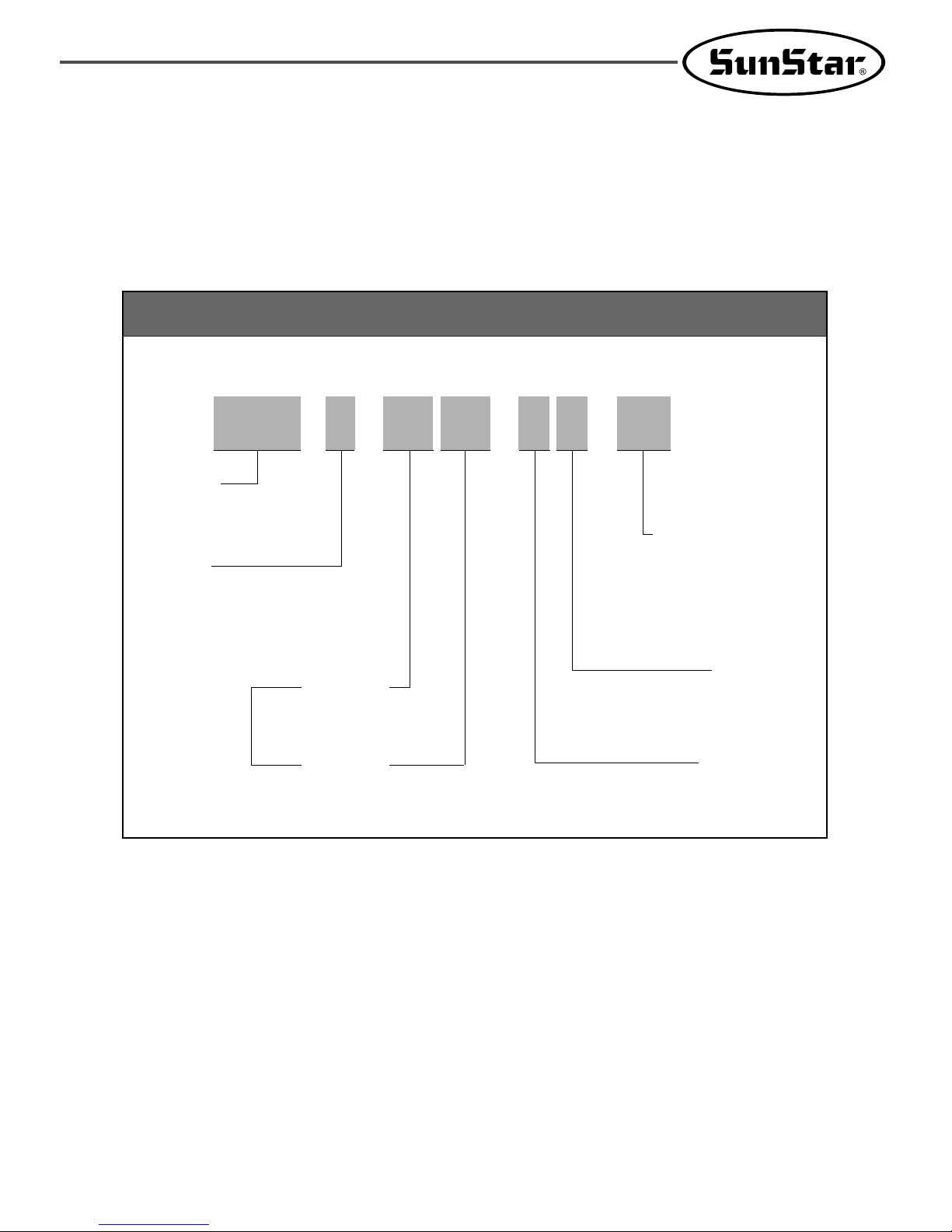
Organization of the SPS/B(A)-Series model
Series
A: Motor belt-type
B: Motor direct drive-type
SunStar
Pattern
System
Sewing area
SPS/B-18 11-H S-20
X : 180mm
Y : 110mm
Feeding Frame Type
Stitch Type
Application
Pattern Type
A : Belt Type
B : Direct Type
Sewing Type
1811 : X(180mm)×Y(110mm)
2211 : X(220mm)×Y(110mm)
Feeding Frame Type
10 : Magnet driven feeding frame
20 : Pneumatic monolithic feeding frame
21 : Pneumatic monolithic feeding frame with two step stroke device
22 : Pneumatic separately-driven feeding frame
23 : Pneumatic separately-driven feeding frame with inverting clamp device
Stitch Type
S : Standard stitch
P : Perfect stich
Applicaion
G : General material
H : Heavy material

1. Machine Safety Regulations 6
2. Specifications of Machine 9
3. Structure of the Machine 10
1) Names of Each Part of Machine 10
2) Inside Structure of ControlBox 11
4. Installation of the Machine 13
1) Environment for Machine Installation 13
2) Electric Installment Conditions 13
3) Assembly of Peripheral Construction Parts 13
5. Preparation Before Operating the Machine 16
1) Setting the Voltage 16
2) How to Supply Oil 17
3) How to Install the Needle Bar 18
4) How to Thread the Upper Thread 19
5) Threading the Lower Thread 19
6) How to Take the Bobbin Case On and Off 20
7) How to Adjust the Tension of the Upper Thread and the Lower Thread 20
8) How to Wind the Lower Thread 21
9) Adjusting the Height of the Presser Foot 21
10) Disposing the Waste Oil 21
11) How to Adjust the Air Pressure 22
12) Adjusting the Speed for Ascension and Descent of Upper Feed Plate 22
13) Standing the Sewing Machine 22
14) Attaching and Removing the V-Belt(A Series) 23
15) Caution When Using the Floppy Disks 24
6. How to Repair the Machine 25
1) Adjusting the Height of the Needle Bar 25
2) Adjusting the Needle and the Shuttle 25
3) Adjusting the Lower Shaft Gear and the Rocking Shaft Gear 26
4) Adjusting the Spring on the Upper Side of the Shuttle 26
5) Adjusting the Height of the Feed Plate 27
6) Adjusting the Presser Foot Devices 27
7) Adjusting the Presser Foot Lifter Cylinder 29
8) Adjusting Accessories for Thread Delay 29
9) Adjusting Accessories for the Wiper 31
10) Adjusting the Trimming Parts 32
11) Adjusting the Main Thread Control Device 35
12) Adjusting the Upper thread Detecting Devices 35
13) Adjusting the Hand Pulley Device 35
14) Adjusting the Winding Device 36
15) How to set the Position of Syncro(A Series) 36
16) Mounting the Direct Motor and Adjusting Method(B Series) 37
CONTENT

17) Adjusting the Height of Needle Plate Support Cover 38
18) Adjusting the Height of Slider 38
19) Adjusting the Upper Under stroke of Feed Plate 39
20) Adjusting the X-Guide Bracket 39
21) Adjusting the Under Feed Plate 40
22) Adjusting the Tension of X-Timing Belt 40
23) Setting the X-Y Origin 41
24) Adjusting the Position of Plastic Blank 42
25) SPS/B(A)-1811(2211)-HS-20 Air System Circuit Diagram 43
7. Cause of Break-Down and Troubleshooting 44
8. SPS/B(A)-1811(2211)-HS-21 46
1) Specification 46
2) Adjusting the Initial Position of Two-Step Stroke Air Cynlinder 46
3) Adjusting the Middle Stop Position of Upper Feed Plate 46
4) Adjusting the Speed for Ascension and Acent of Upper Feed Plate 47
5) How to Use the Pedal Switch 47
6) SPS/B(A)-1811(2211)-HS-21 Air System Circuit Diagram 48
9. SPS/B(A)-1811(2211)-HS-22 49
1) Specification 49
2) Adjusting the Angle of Upper Feed Plate(Both Right and Left) 49
3) Adjusting the Initial Position of Air Cyliner 49
4) Adjusting the Middle Stop Position of the Left Upper Feed Plate 49
5) Adjusting the Speed for Ascension and Descent of Upper Feed Plate 50
6) How to Use the Pedal Switch 50
7) SPS/B(A)-1811(2211)-HS-22 Air System Circuit Diagram 52
10. SPS/B(A)-1811(2211)-GS-20(21, 22, 23) 53
1) Machine Sepecifications 53
2) How to Hook the Upper Thread 53
11. SPS/B(A)-1811(2211)-HP(GP)-
54
1) Specifications 54
2) How to Attach the Needle 55
3) How to Hook the Upper Thread 55
4) How to Hook the Lower Thread 55
5) Adjusting the Spring on the upper Side of the Shuttle 56
6) Adjusting the Moving Knife and the Fixed Knife 56
12. Drawing of Table 57
6
11
MACHINE SAFETY REGULATIONS
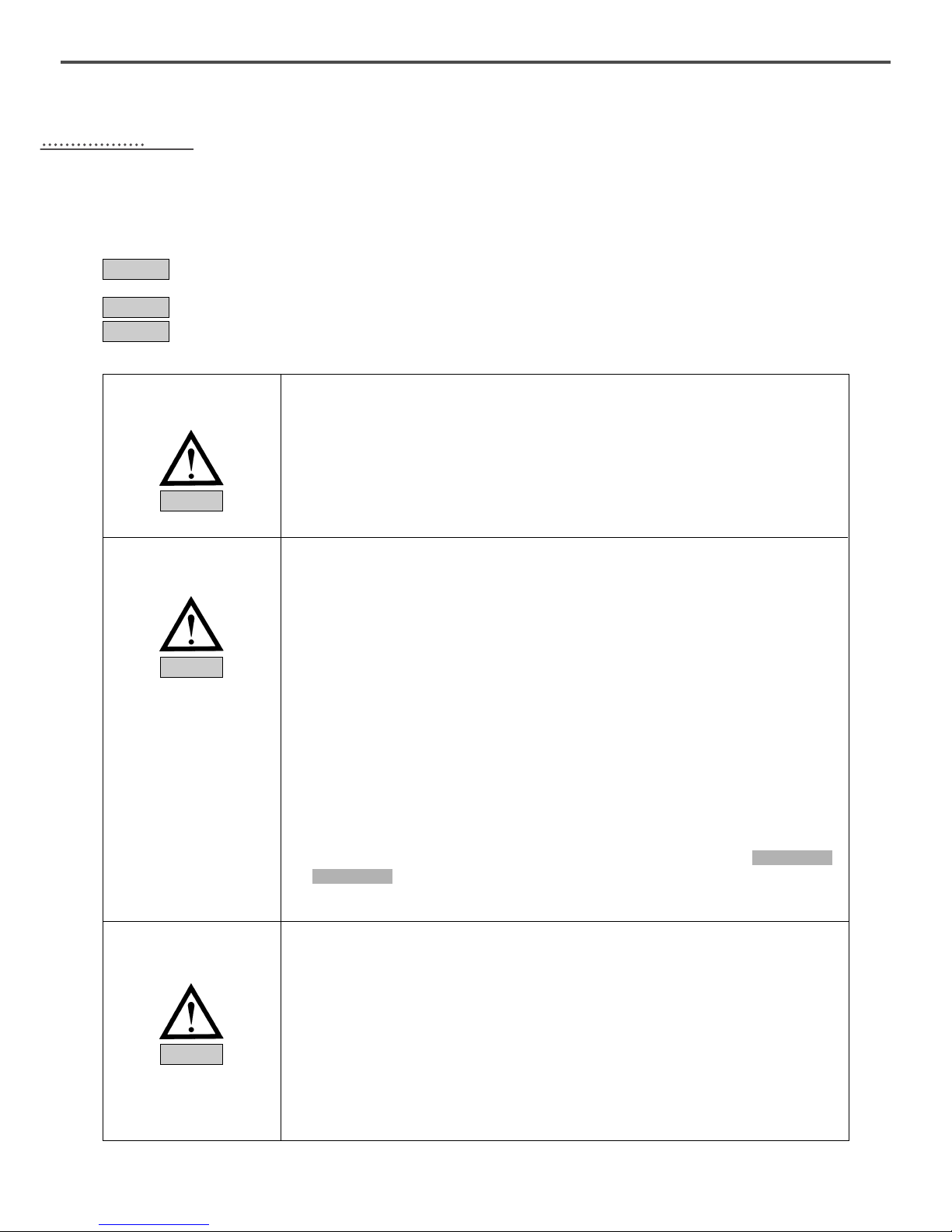
Safety instruction on this manual are defined as Danger, Warning and Notice.
If you do not keep the instructoins, physical injury on the human body and machine damage might be occurred.
: This indication should be observed definitely. If not, danger could be happen during the installation,
conveyance and maintenance of machines.
: When you keep this indication, injury from the machine can be prevented.
: When you keep this indication, error on the machine can be prevented.
Danger
Warning
Notice
Those in charge of transporting the machine should know the safety regulations
very well. The following indications should be followed when the machine is being
transported.
ⓐ More than 2 people must transport the machine.
ⓑ To prevent accidents from occurring during transportation, wipe off the oil on the
machine well.
1-1) Machine
Transportation
Danger
The machine may not work well or breakdown if installed in certain places, Install
the machine where the following qualifications agree.
ⓐ Remove the package and wrappings starting from the top. Take special notice
on the nails on the wooden boxes.
ⓑ Dust and moisture stains and rusts the machine. Install an airconditioner and
clean the machine regularly.
ⓒ Keep the machine out of the sun.
ⓓ Leave sufficient space of more than 50cm behind, and on the right and left side
of the machine for repairing.
ⓔ Do not operate in explosive atmospheres. To avoid explosion, do not operate
this machine in an explosive atmosphere including a place where quantities of
erosol spray product are being used or where oxygen is being administered
unless it has been specifically certified for such operation.
ⓕ The machines were not provided with a local lighting due to the feature of
machine.
Therefore the illumination of the working area must be fulfilled by end user.
[ Reference ] Details for machine installment are described in 4. Machine
Installment.
1-2) Machine
Installation
Notice
When the machine needs to be repaired, only the assigned troubleshooting
engineer educated at the company should take charge.
ⓐ Before cleaning or repairing the machine, turn off the Main power and wait
4 minutes till the machine is completely out of power.
ⓑ Not any of the machine specifications or parts should be changed without
consulting the company. Such changes may make the operation dangerous.
ⓒ Spare parts producted by the company should only be used for replacements.
ⓓ Put all the safety covers back on after the machine has been repaired.
1-3)Machine Repair
Danger
7
SPS/B(A)-1811(2211) Series are made for industrial use to perform pattern sewing
for fabrics or its similar materials. Please observe the following principles.
ⓐ Read the manual to understand on the operation of machine perfectly.
ⓑ Wear suitable clothes and cap for safe operation.
ⓒ During operation, don’t make you body close to operating part of machine such
as needle, hook, take-up lever or pulley.
ⓓ Do not remove a safety plate and covers during operation
ⓔ Be sure the grounding lines in connected.
ⓕ Before opening electricity box such as control box, cut off the supply of
electricity and confirm if the switch is “off”.
ⓖ When inserting thread into a needle or before inspecting after sewing, be sure
the machine is stopped.
ⓗ Do not turn on the power during pedaling.
ⓘ Do not use several motor per a electric outlet.
ⓙ Install the machine apart from noise occurrence area such as high frequency
welding machines as far as possible.
ⓚ Be careful-When the upper feed plate comes down to press. Otherwise, the
finger or hand hight be hurt at smacking.
1-4)Machine
Operation
Warning
Notice
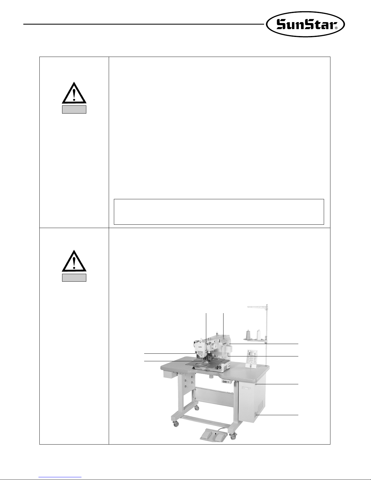
[ Warning ]
Belt will crush or amputate finger or hand, keep cover in place before
operating, turn off power before inspecting or adjusting.
ⓐ Safety label : It describes cautions during operating the machine.
ⓑ Thread take-up lever : It prevents from any contact between body and take-up
lever.
ⓒ Servo motor cover : It prevents from insertion of hands, feet or clothes by motor
and Y-drive shaft.
ⓓ Step motor cover : It prevents from accidents during rotation of step motors.
ⓔ Label for specification of power : It describes cautions for safety to protect
against electric shock during rotating the motors.
ⓕ Safety plate : It protects eyes against needle breaks.
ⓖ Finger guard : It prevent from contacts between a finger and needle.
1-5)Devices for
Safety
ⓐⓑ
ⓕ
ⓖ
ⓒ
ⓓ
ⓐ
ⓔ
8
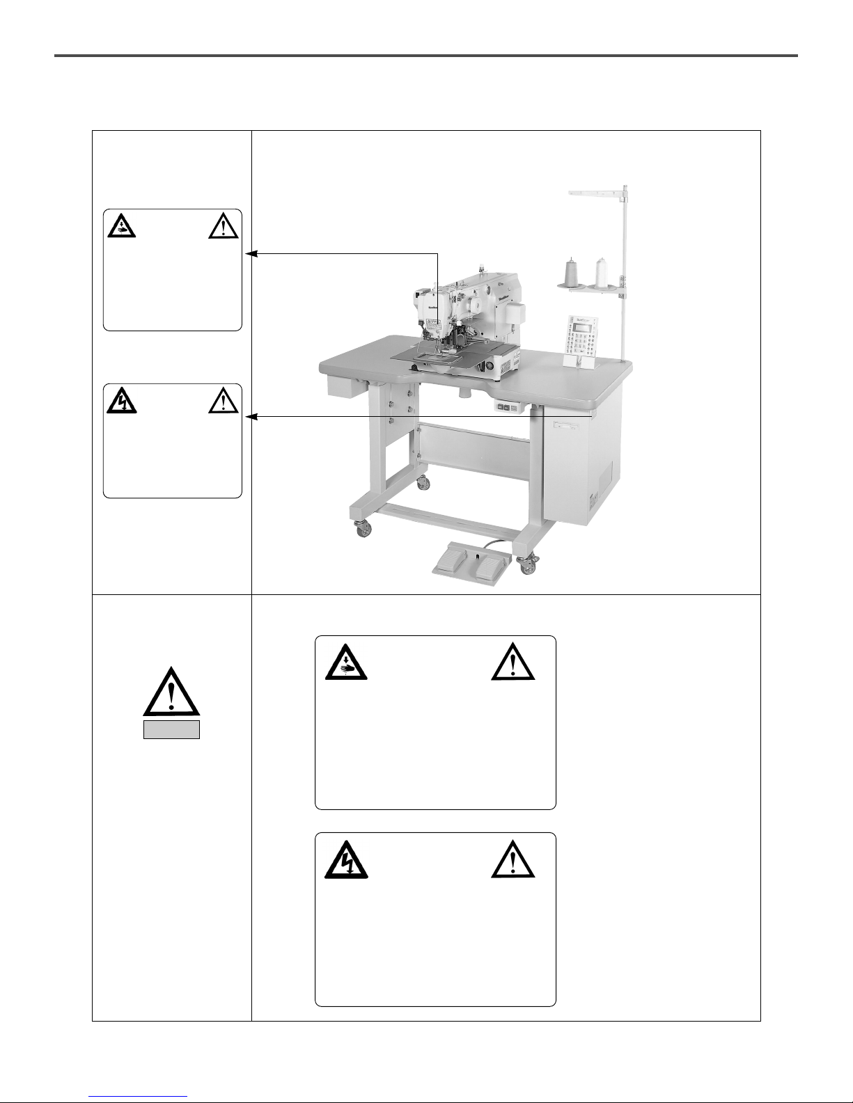
Caution mark is attached on the machine for safety.
When you operate the machine, observe the directions on the mark.
Position of Warning Mark
[ View from the right-front ]
1-6) Caution Mark
Position
Caution
1)
1-7) Contents of Marks
Warning
2)
CAUTION
경고
Do not operate without finger guard
and safety devices. Before threading,
changing bobbin and needle, cleaning
etc. switch off main switch.
손가락 보호대와 안전장치 없이 작동하지 마
십시오.
실, 보빈, 바늘교환시나 청소전에는 반드시
주전원의 스위치를 꺼 주십시오.
CAUTION
경고
Hazardous voltage will cause injury.
Be sure to wait at least 360 seconds
before opening this cover after turn
off main switch and unplug a power
cord.
고압 전류에 의해 감전될 수 있으므로 커버
를 열 때는 전원을 내리고 전원 플러그를 뽑
고 나서 360초간 기다린 후 여십시오.
CAUTION
경경 고고
Do not operate without finger guard and safety
devices. Before threading, changing bobbin and
needle, cleaning etc. switch off
main switch.
손가락 보호대와 안전장치 없이 작동하지
마십시오.
실, 보빈, 바늘교환시나 청소전에는 반드시 주전
원의 스위치를 꺼 주십시오.
CAUTION
경경 고고
Hazardous voltage will cause injury.
Be sure to wait at least 360 seconds before
opening this cover after turn off main switch and
unplug a power cord.
고압 전류에 의해 감전될 수 있으므로 커버를
열 때는 전원을 내리고 전원 플러그를 뽑고 나
서 360초간 기다린 후 여십시오.
9
22
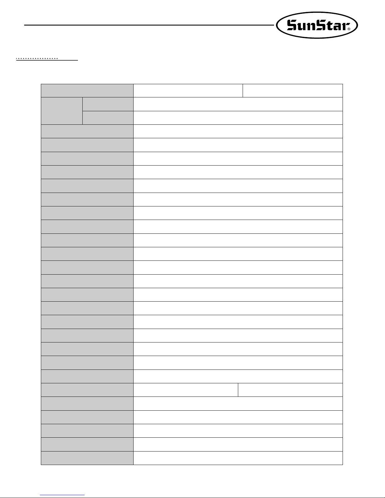
SPECIFICATIONS OF THE MACHINE
Series type
Sewing Speed
Stitch Length
Needle
Needle Bar Stroke
Hook
Bobbin Case
Bobbin
Presser Foot Stroke
Lifting Amount of Presser Foot
Lifting Amount of Feed Frame
Feeding System
Emergency Stop Function
Pattern Select Function
Memory
Memory Backup
2nd Origin Function
Maximum Speed Restriction
Number of Patterns
Safety Device
Main Motor
Power Consumption
Recommended Temperature
Recommended Humidity
Power
Pneumatic Pressure
X(horizontal)×Y(vertical) :180mm×110mm
X(horizontal))×Y(vertical) :220mm×110mm
Max. 2000spm(Stitch Length:3mm or less)
0.1~12.7mm
DP×17, DP×5
41.2mm
Semi-Rotary Large Shuttle Hook
Bobbin Case for Semi-Rotary Large Shuttle Hook
Bobbin for Large Shuttle Hook
Standard 4mm[0.5~10mm]
Max. 20mm
25mm [Max. 30mm]
Feeding by Pulse Motor
Available During Sewing Operation
Pattern No. can be Selected From No.1 to No.999
3.5”Floppy Diskette. (2HD)
The Working Point is Stored in the Memory when the Machine Stops Abnormally
Another Origin Point can be Set by Using Jog Key
The Maximum Speed can be Limited from 200 to 2.500spm
Max. 691 Patterns/Disk
Emergency Stop Function, Maximum Speed Limit Function
Direct Drive AC Servo Motor 550W Servo Motor
600VA
5℃~40℃(41。F~104。F)
20%~80%
1ф: 100~240V, 3ф: 200~40V, 50/60HZ
5~5.5 kgf/cm
2
(0.49~0.54Mpa)
Sewing Area
1811
2211
SPS/B-1811(2211)(Motor direct drive-type) SPS/A-1811(2211)(Belt drive-type)
10
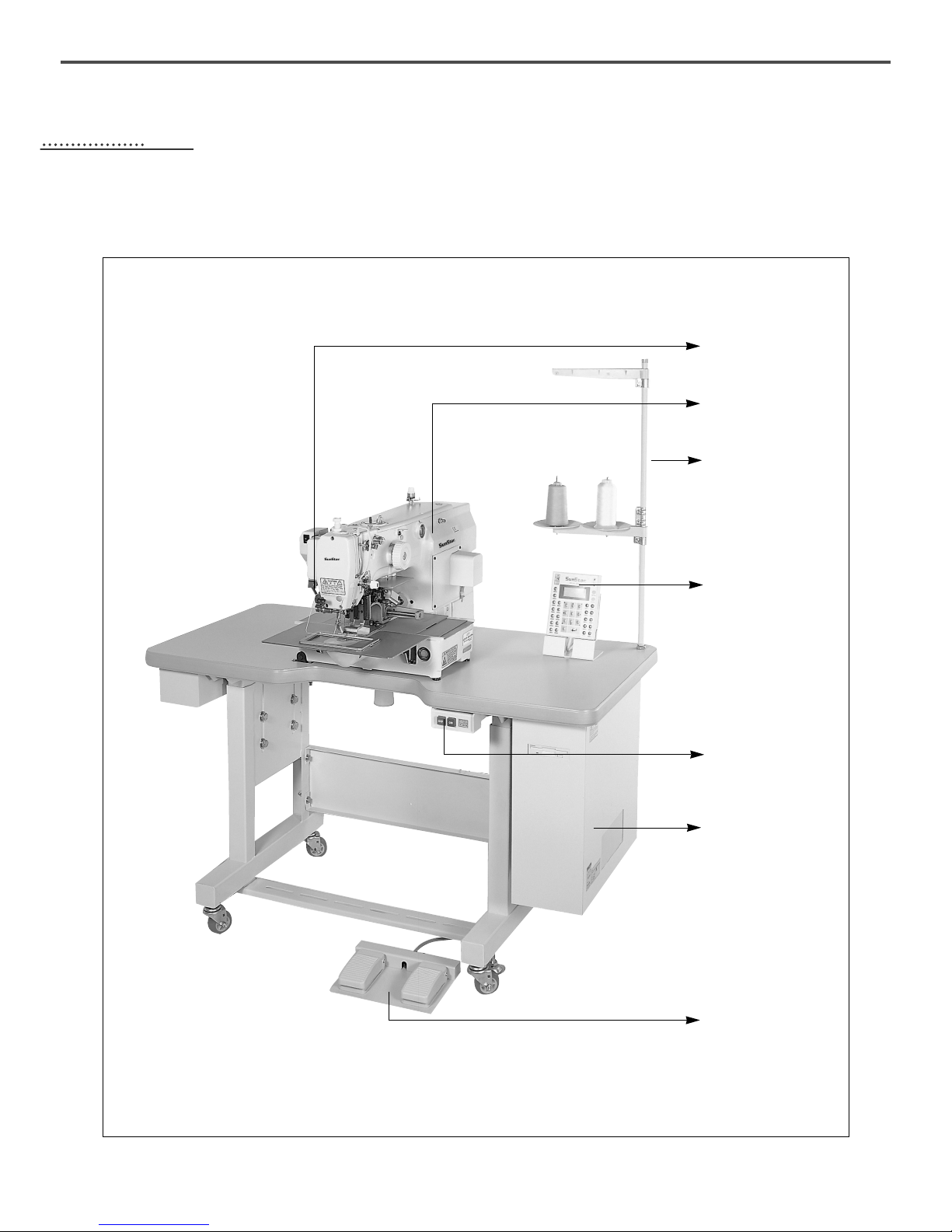
STRUCTURE OF THE MACHINE
1) Names of Each Parts of Machine
Pause Switch
Arm
Thread Stand
Operation Box
Power Switch
Control Box
Pedal Switch
33
11
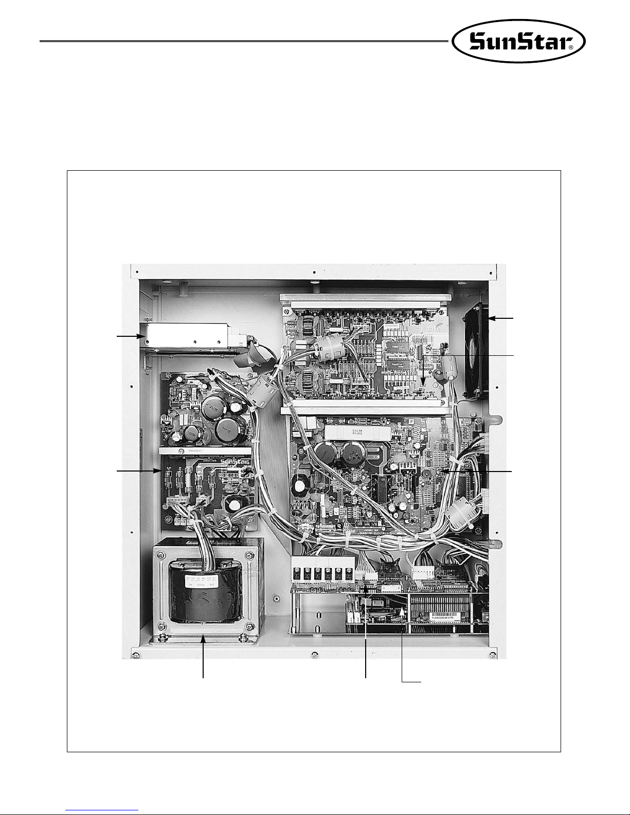
2) Inside Structure of Control Box
① SPS/B-1811(2211)
Floppy
Disk
Drive
Main
Board
Main Shaft
Motor
Drive
Board
Fan
Step Motor
Drive
Board
Transformer
IO Board
386 CPU Board
12
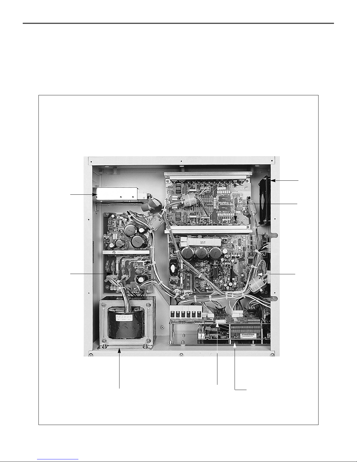
② SPS/A-1811(2211)
Floppy
Disk
Drive
Main
Board
Main
Shaft
Motor
Drive
Board
Fan
Step
Motor
Drive
Board
Trans
IO Board
386 CPU Board
13
44
INSTALLATION OF THE MACHINE
1) Environment for Machine Installation
A. Do not use the machine where the voltage is over regular voltage ±10% to prevent accidents.
B. Check the indicated pressure of the devices that use atmospheric pressure such as the air cylinder to
prevent any accidents from occurring.
C. For safe operation of the machine, use the machine under the following conditions.
Surrounding Temperature During Operation : 5℃~40℃
Surrounding Temperature During Maintenance : -10℃~60℃
D. Humidity : Between 20~80%(Relative humidity)
2) Electric Installment Conditions
A. Power Voltage
· The power voltage must be between regular voltage ±10%.
· The frequency of the power should be regular frequency (50/60HZ)±1%.
B. Electromagnetic Wave Noise
Use separate power with strong magnetics or high frequency products, and do not leave the machine near
them.
C. Use low voltage when supplements or accessories are being adhered.
D. Be careful not to have water or coffee be spilled into the Controller and Motor.
E. Do not drop the Controller or Motor.
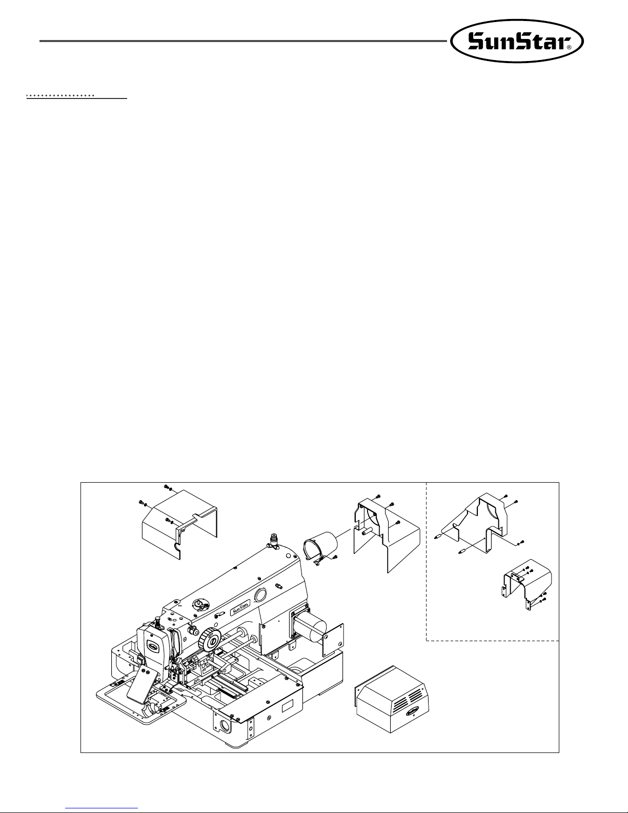
3) Assembly of Peripheral Construction Parts
A. Attach the X-motor cover, Y-motor cover, motor cover and belt cover to the back side of machine with using
fixing screws.
(In case of A series, attach the belt cover, the motor cover and the driving shaft cover to the back of the
sewing machine.)
[ Fig. 1 ]
Belt Cover
Belt Cover
Driving Shaft Cover
A series
Motor Cover
Y-Motor Cover
X-Motor Cover
14
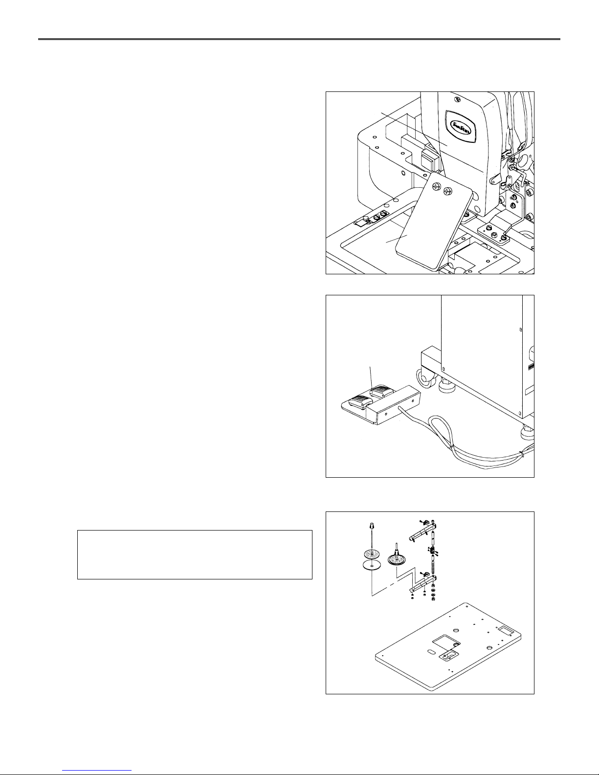
B. Attach the safe plate to the side plate.
(You should attach it to prevent from safe accident.)
C. Connect a plug of pedal switch with control box.
[ Fig. 2 ]
[ Fig. 3 ]
Safety Plate
Face Plate
Pedal Switch
[ Caution ]
You can be hurt by the dropping device during
installation so be careful about it.
[ Fig. 4 ]
D. Install a bobbin holder on a table.
15
[ Fig. 5 ]
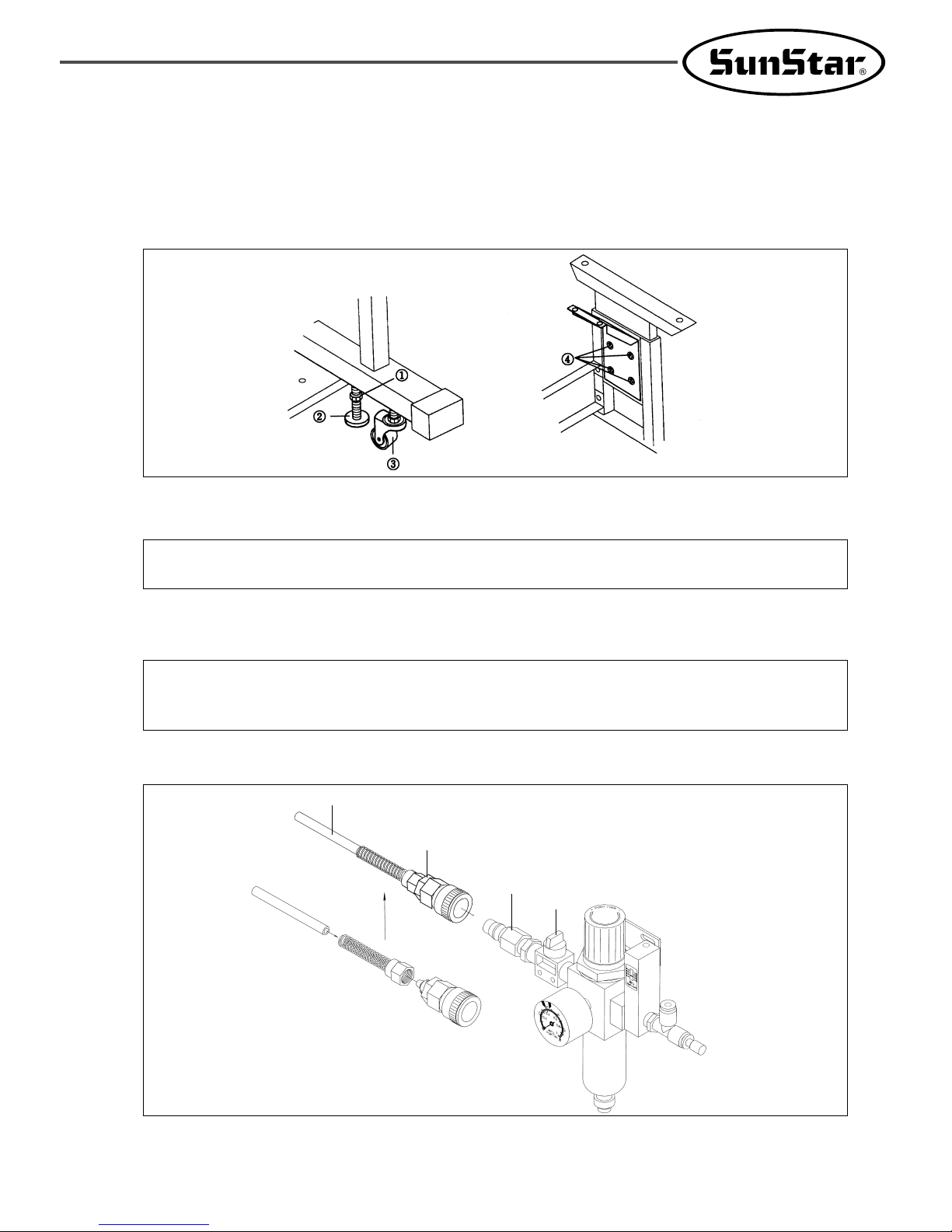
E. Table leg holder
▶ Method
ⓐ Loosening the nut ① and turn and raise the label adjuster ② until the caster ③ is raced.
ⓑ After installation, fasten the nut ① and fix the label adjuster ②.
ⓒ With the bolt ④, adjust the height of table by loosening 8 different spots.
F.How to attach the accessories for air pressure control.
ⓐ Connect air hose ② to quick joint socket.
ⓑ Connect quick joint socket ① and quick joint plug ③.
ⓒ Open finger valve ④ and flow air in. Then, adjust the air pressure to 0.49~0.54MPa(5~5.5kgf/㎠).
[ Coution ]
For safety, work with the power cut off.
[ Caution ]
When the air pressure goes down (under 4kgf/㎠), an error is indicated and the machine operation is stopped.
Error message : Err 24 (Low Pressure ! )
[ Note ] When the finger valve ④ is closed after use, the remaining air is rejected and the pressure is
adjusted to 0Mpa(0kgf/㎠ ).
[ Fig. 6 ]
④
①
②
③
16
55
PREPARATION BEFORE OPERATING THE MACHINE
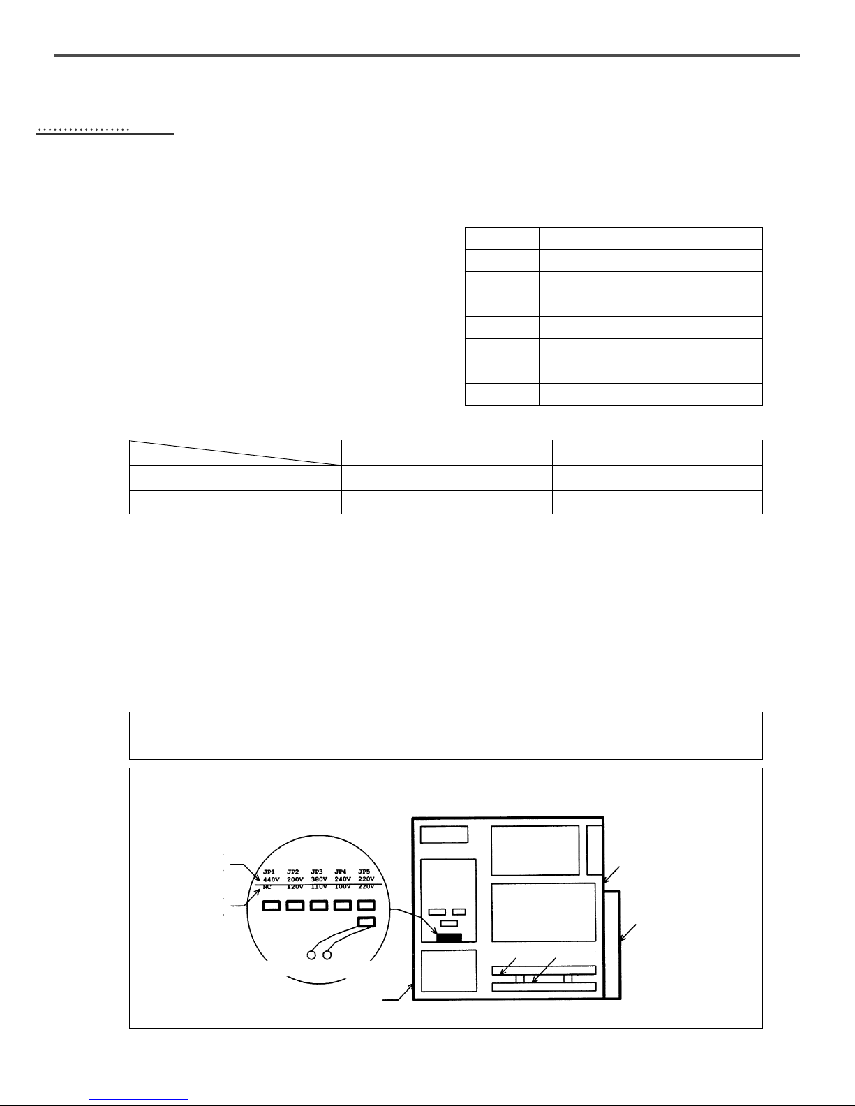
1) Setting the Voltage
A. If a cover of electronically controlled pattern sewing
machine is taken off, inside contents are as same as
[ Fig. 1 ].
B. Confirm the position of change connector of power
voltage on power board [Refer Fig. 1] and transformer
if they are properly selected for input voltage like
Table 1 and 2.
EX ) If power voltage is 220 V:
The model of used transformer is “SPS--
220”and it is normal for the change connector of
power voltage to be placed on “JP5”.
※ Sticker for transformer model is attached to the top
side of transformer.
C. Check if a power switch is for 1 phase and 3 phase.
D. If the setting of ② and ③ is not proper, damage from breakdown can be occurred. If there is any problem,
follow below direction.
ⓐ If the position of change connector is wrongly placed :
① Separate the connector linked to transformer from CN7, CN8 and CN9 of power borad.
② Insert the power change connector into a proper position on Table 1.
③ Reconnect the connector linked to transformer to CN7, C8 and CN9 of power board.
ⓑ If the specification of used transformer is not in a accord with that of power switch, ask to the place where
you purchased for troubleshooting.
[ Table 1. Position of change connector of voltage ]
[ Table 2. Modle of used transformer according to the input power voltage ]
[ setting of change connector of power voltage ]
[ Fig. 7 ]
Input Voltage
95V~105V
106V~115V
116V~125V
200V~230V
231V~245V
345V~415V
416V~480V
Position of Change Connector of Power Voltage
JP4
JP3
JP2
JP5
JP4
JP3
JP1
100V~120V
220V~440V
Power Voltage
SPS/B(A)-1306(1507,1310)-X X - X X
″SPS-1306-110″
″SPS-1306-220″
SPS/B(A)-1811(2211)-X X - X X
″SPS-1811-110″
″SPS-1811-220″
Model
[ Caution ]
Before turning on the power switch, air should be filled with.
If an Input Power
voltage is Over 220V
If an Input Power
Voltage is 110V
Change Connector of Power Voltage
Front-Side Cover
Floppy
Disk Drive
Power Board
Step Motor
Drive Board
Main Shaft
Motor Drive Board
Back-Side Cover
Back-Side Cable Cover
I/O Board
CPU Board
CN7
CN8
CN9
Transformer
Caution 1)
17
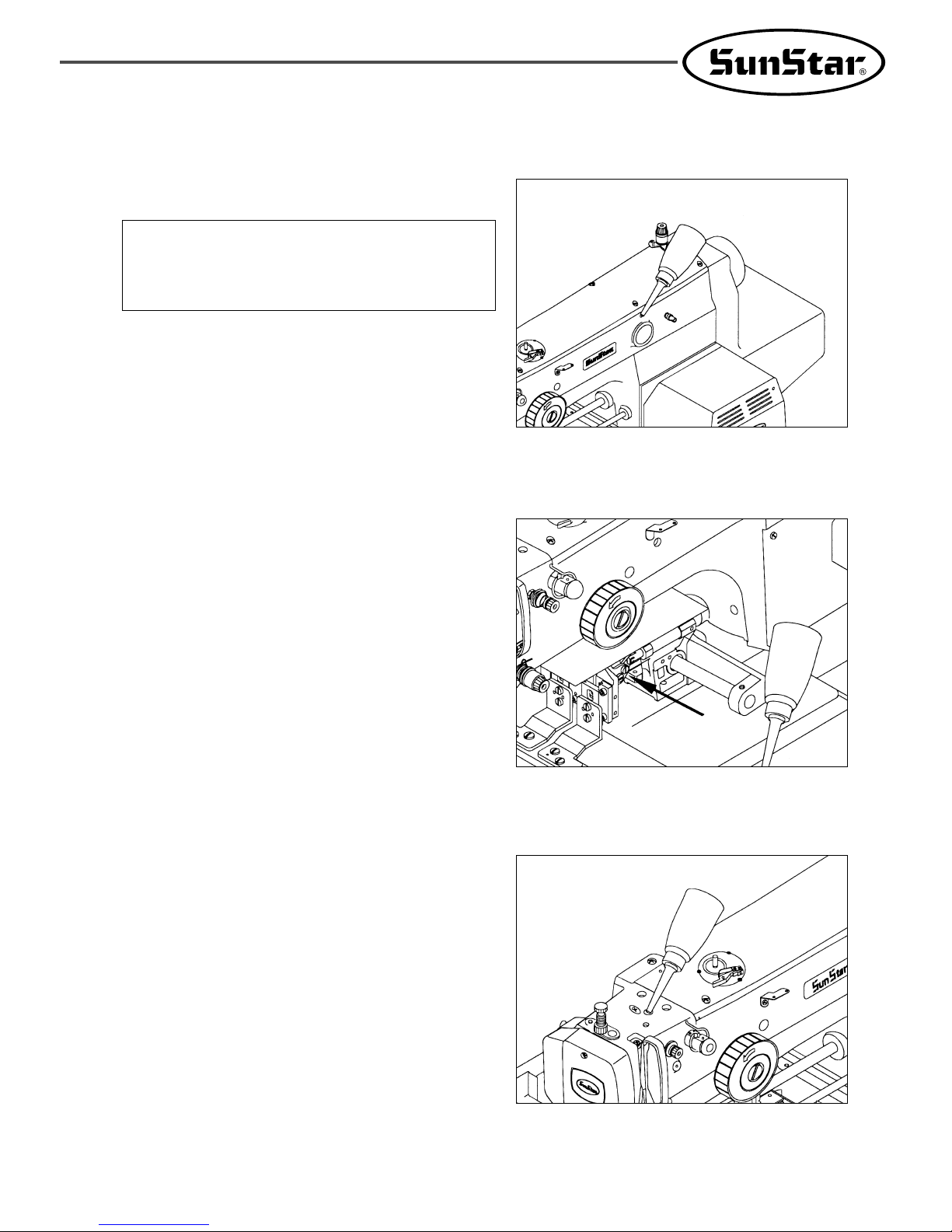
A. Check the amount of oil left in the oil tank which is
installed on the arm and supply oil sufficiently.
B. As shown in the picture, move the feed bracket in the
direction of “A”and supply oil into the bed oil window
through the hole on the bed cover.
C. Supply oil into the hole in the upper part of the arm.
[ Fig. 8 ]
[ Fig. 9 ]
[ Fig. 10 ]
[ Caution]
Be sure to supply oil when operating the machine
for the first time or when the machine has not
been used for long time.
2) How to Supply Oil
A

18
[ Fig. 12 ]
Sillicon Oil Tank
D. Open the hook cover and supply oil till the shuttle
race ring is surrounded by oil. Put the hook cover
back on after finishing.
E. Supply silicon oil into the silicon oil tank which is
installed on the right side of the arm.
[ Fig. 11 ]
Shuttle Race Ring
Hook Cover
[ Caution ]
For safety, keep the hook cover covered during operating.
3) How to Install the Needle Bar
Unfasten the needle fixing screw on the needle bar.
Then, with the needle groove facing forward, push the
needle until the upper end touches the needle hole of the
needle bar. Fix the needle in with the needle fixing screw.
[ Fig. 13 ]
Screw
Needle
 Loading...