

Sunstar SPS A-1306, SPS A-1811, SPS B-1507 User Manual

SuiiHtar
USSR'S
INVERTING
MRNURL
ClflMPD^VIC^S
SPS/R(B)-S€RI€S
Electronic
Pattern
Sewing
Machine
1)
2)
FOR
PLEASE
BEFORE
KE?
FOR
BREAKS
AT
MOST
CERTAINLY
STARTING
TH»
MANUAL
REF5)ENCE
DOWN.
USE
WHEN
WITH
READ
USE
IN
SAFE
EASINESS,
THIS
MANUAL
PLACE
THE
MACHINE

1.
Thank
experience
will
functions,
more
2.
Please
sure
3.
The
product
4.
This
machine.
you
manufacture
sophisticated
read
to
properly
specifications
product
for
purchasing
accumulated
industrial
high
performance,
design
this
user's
use
performance,
Is
designed,
It
should
manual
the
of
the
without
not
be
our
product.
in
industrial
sewing
powerful
to
meet a number
machine
machine
prior
manufactured,
used
for
sewing
machines,
thoroughly
to
enjoy
are
subject
notice.
other
Based
operation,
its
and
than
on
the
machine
which
enhanced
of
user's
before
using
full
performance.
to
change,
sold
as
industrial
rich
expertise
production,
deliver
needs.
the
aimed
an
industrial
purpose.
SUNSTAR
more
durability,
machine.
to
enhance
and
diverse
and
Make
sewing
SUNSTAR
CO.,
LTD.
COMTEMTS
1.
Notice
Before
2.
Inverting
1.
Installing
2.
Adjusting
3.
Installation
4.
Adjusting
5.
Removing
3.
Inverting
1.
Installing
2.
Adjusting
3.
Adjusting
4.
Adjusting
5.
Adjusting
6.
Adjusting
7.
Removing
Clamp
Clamp
Using
Devices
the
Inverting
the
Wiper
and
Adjustment
the
Reversal
the
Inverting
Devices
the
Inverting
the
Wiper
the
Inverting
the
Middle
the
Position
the
Label
the
Inverting
of
SPS/A-1306
Clamp
Devices
Parts
of
Pneumatic
Feeding
Clamp
Devices
of
SPS/A-1811
Clamp
Devices
Parts
Presser
Stop
Position
of
the
Inverting
Guide
Clamp
Devices
Frame
Plate
Feeding
of
Series
Control
Series
Frame
Reversal
Clamp
Feeding
Devices
Parts
Crank
Frame
-
-
4
5
5
6
7
8
9
10
10
10
10
12
12
13
13
4.
SPS/B-1507
1,
Specifications
2.
Structure
2,
Installation
5.
The
Use
of
1.
2.
6.
Parts
A.
B.
C.
D.
E.
F.
G.
H.
I.
Pattem
Adding
Programming
the
Book
Inverting
Inverting
Wiper & Presser
Pneumatic
Pneumatic
Pneumatic
Inverting
Inverting
Pneumatic
Series
Inverting
of
unit
of
machine
Inverting
Codes
Clamp
Clamp
Control
Control
Control
Clamp
Clamp
Control
Functions
by
for
Reversal
Devices
Devices
Foot
Mechanism
Mechanism
Mechanism
Mechanism
Devices
Devices
Mechanism
Clamp
Using
Mechanism
Mechanism
Mechanism
Mechanism
Devices
the
Inverting
to
the
Pattems
(SPS/A-1306
(SPS/A-1811
(SPS/A-1306
(SPS/A-1306
(SPS/A-1811
(SPS/A-2516
(SPS/B-1507HJ)
(SPS/B-1507HJ)
Code
Already
Programmed
Series)
Series)
Pneumatic
Electronic
Series)
Machine
Machine
Series)
Seires)
Series)
14
14
15
16
18
18
21
23
25
26
28
30
32
34
36
38
42
Attachments
1.
Pneumatic
2.
Pneumatic
3.
Pneumatic
circuit
diagram
circuit
diagram
circuit
diagram
for
SPS/A-1306
for
SPS/A-1811
for
SPS/B-1507
series
tumover
series
tumover
series
tumover
device
device
device
42
48
52
1
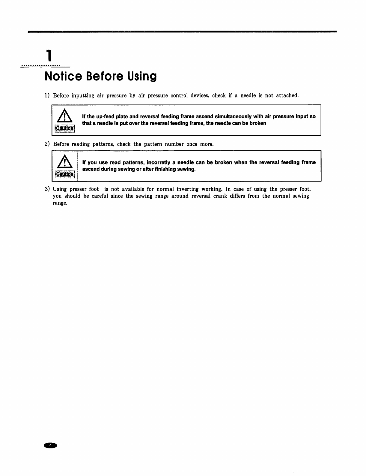
Notice
1)
Before
2)
Before
3)
Using
you
range.
inputting
A
reading
A
presser
should
If
that a needle
If
ascend
be
Before
air
pressure
the
up-feed
patterns,
you
foot
careful
use
read
during
is
not
since
plate
is
put
check
patterns,
sewing
available
the
Using
by
air
pressure
and
reversal
over
the
reversal
the
pattern
incorretly a needle
or
after
finishing
for
sewing
range
control
feeding
feeding
number
sewing.
normal
inverting
around
devices,
frame
ascend
frame,
once
can
reversal
check
simultaneously
the
needle
more.
be
broken
working.
In
crank
if a needle
can
when
case
differs
be
of
from
is
with
broken
the
reversal
using
not
air
pressure
the
the
normal
attached.
Input
feeding
presser
frame
foot,
sewing
so
Inverting
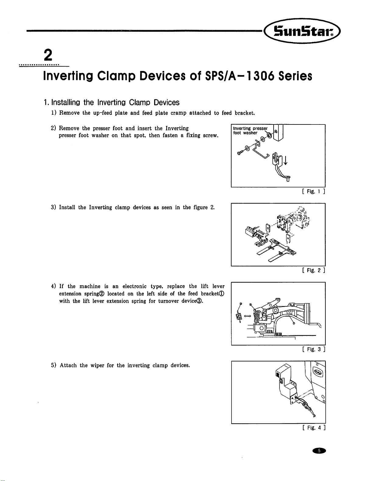
1.
Installing
1)
Remove
Clamp
the
Inverting
the
up-feed
Clamp
plate
and
Devices
of
Devices
feed
plate
cramp
attached
SPS/A-1306
to
feed
bracket.
Series
2)
Remove
presser
3)
Install
4)
If
the
extension
with
the
the
presser
foot
washer
the
Inverting
machine
spring®
lift
lever
foot
and
on
that
clamp
is
an
electronic
located
extension
on
spring
insert
the
spot,
then
devices
the
as
type,
left
side
for
Inverting
fasten a fixing
seen
in
the
figure
replace
of
turnover
the
the
feed
device®.
screw.
2.
lift
lever
bracket®
Inverting
foot
washer
presser
[
[
Fig.
1
Fig.
2
5)
Attach
the
wiper
for
the
inverting
clamp
devices.
[
Fig. 3 .
Fig. 4 ]
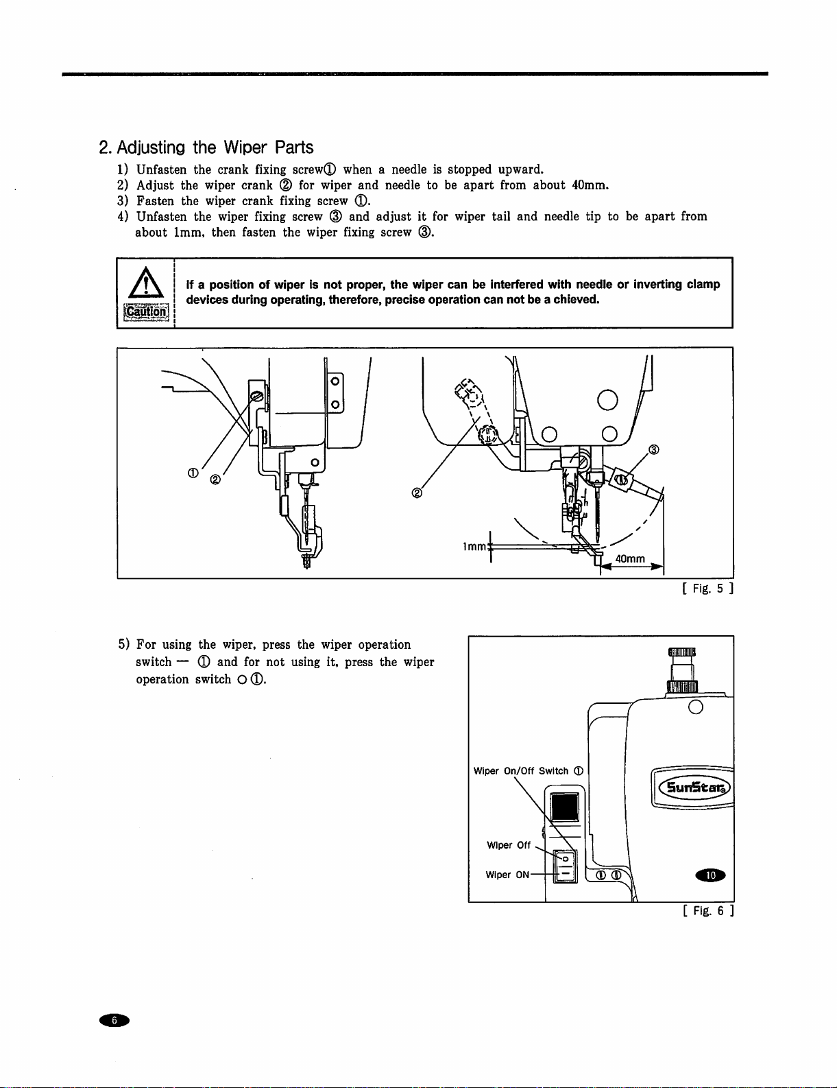
2.
Adjusting
1)
Unfasten
2)
Adjust
3)
Fasten
4)
Unfasten
about
the
the
the
the
the
1mm,
Wiper
crank
wiper
crank
wiper
crank
wiper
then
fasten
Parts
fixing
screw®
(D
for
fixing
fixing
screw
the
when a needle
wiper
and
screw
®.
(D
and
adjust
wiper fixing
screw
is
needle
to
it
for
d).
stopped
be
apart
wiper
tail
upward.
from
about
and
needle
40mm.
tip
to
be
apart
from
5)
For
using
switch — ®
operation
If a position
devices
the
and
switch
of
during
wiper,
press
for
O®.
wiper
is
not
operating,
not
therefore,
the
wiper
using
it,
proper,
the
precise
operation
press
the
wiper
operation
wiper
can
be
interfered
can
not
with
needle
be a chieved.
or
inverting
40mm
clamp
[
Fig. 5 ]
wiper
Wiper
Wiper
On/Off
Off
ON-
Switch
S
®
[
Fig.
6

3.
Installation
A
A.
For
1)
2)
3)
4)
5)
Make
safety
pneumatic
Attach
Remove
figure
Connect
Open
Pull
the
turned
pressure
6)
Pull
the
the ( + ) direction,
decreases.
and
Adjustment
sure
that
the
power
accidents.
type
the
pressure
the
plug®
below.
the
air
the
finger
pressure
in
the ( + ) direction,
decreases.
pressure
Set
adjusterQ
attached
hoses®,®
valve®
adjuster®
Set
adjuster®
the
the
air
pressure
the
pressure
Hand
to
and
handle
air
handle
e
of
Pneumatic
is
turned
off
during
to
the
rear
to
T(D,
and
the
corresponding
pass
the
air
for
the
the
pressure
pressure
for
at
upper
increases.
at
the
appropriate
Control
parts
instaiiation
side
of
the
table
insert
it
into
solenoid
to
move
in.
reverse
increases.
the
When
device
When
appropriate
feed
in
the
it
is
turned
level
Solenoid
Reverse
(0.5~0.55MPa)
Valve
Device
Parts
and
leg
using
T®.
Connect
entrances.
in
the
arrow
it
is
turned
level
of
0.5~0.55MPa
arrow
direction.
in
the
of
0.4-0.45MPa
for
adjustment
the
the
in
order
screw.
air
hose®
direction.
in
the
(-)
When
(-)
direction,
(4~4.5Kfg/crf).
Solenoid
Reverse
(0.4~0.45MPa)
to
prevent
as
in
the
When
it
is
direction,
the
(5~5.5Kgf/cril).
it
is
turned
the
pressure
Valve
Device
in
for
Handle
[
Fig. 7 ]
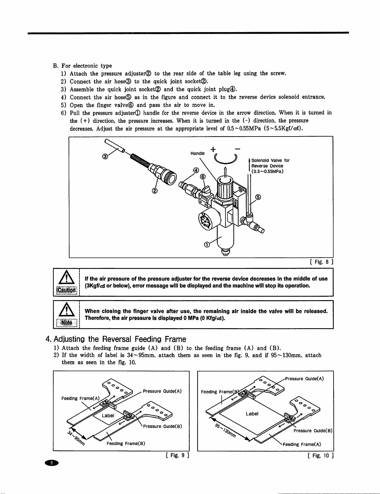
B.
For
electronic
1)
Attach
2)
Connect
3)
Assemble
4)
Connect
5)
Open
6)
Pull
the
decreases.
type
the
the
the
the
the
finger
the
pressure
(+)
direction,
Adjust
pressure
air
air
adjuster(D
hosed)
quick
joint
hosed)
valve®
adjuster®
the
pressure
the
air
to
the
to
the
quick
socket®
as
in
the
figure
and
pass
handle
for
increases.
pressure
at
rear
side
joint
socketd).
and
the
quick
and
connect
the
air
to
the
reverse
When
the
appropriate
Handle
of
joint
move
device
it
is
turned
the
table
plug®.
it
to
in.
in
level
of
leg
using
the
the
reverse
the
arrow
in
the
(-)
0.5~0.55MPa
device
direction.
direction,
(5~5.5Kgf/cnl).
Solenoid
Reverse
(0.5~0.55MPa)
screw.
solenoid
When
the
pressure
Valve
for
Device
entrance.
it
is
turned
in
aunon
A
4.
Adjusting
1)
Attach
2)
If
the
them
Feeding
•KN,.
If
the
air
(3Kgf/cd
When
ciosing
Therefore,
the
the
feeding
width
of
as
seen
in
Frame(A)
^
pressure
or
the
of
below),
error
the
finger
air
pressure
Reversal
frame
guide
label
is
34~95mm,
the fig.
10.
^
Label
Feeding
Frame(B)
the
pressure
message
valve
is
Feeding
(A)
adjuster
will
after
displayed 0 MPa
Frame
and
(B)
attach
^Pressure
^Pressure
Gulde(A)
Gulde(B)
for
be
displayed
use,
the
to
the
them
as
the
reverse
and
remaining
(0
Kfg/cd).
feeding
seen
in
Feeding
Frame
device
the
machine
air
Inside
frame
(A)
the fig.
decreases
will
stop
the
and
9,
and
if
Labe
In
the
middle
Its
operation.
valve
will
be
(B).
95~130mm,
Pressure
Pressure
Feeding
[
Fig.
of
use
released.
attach
Gulde(A)
Guide(B)
Frame(A)
8
[
Fig.
9
[
Fig.
10
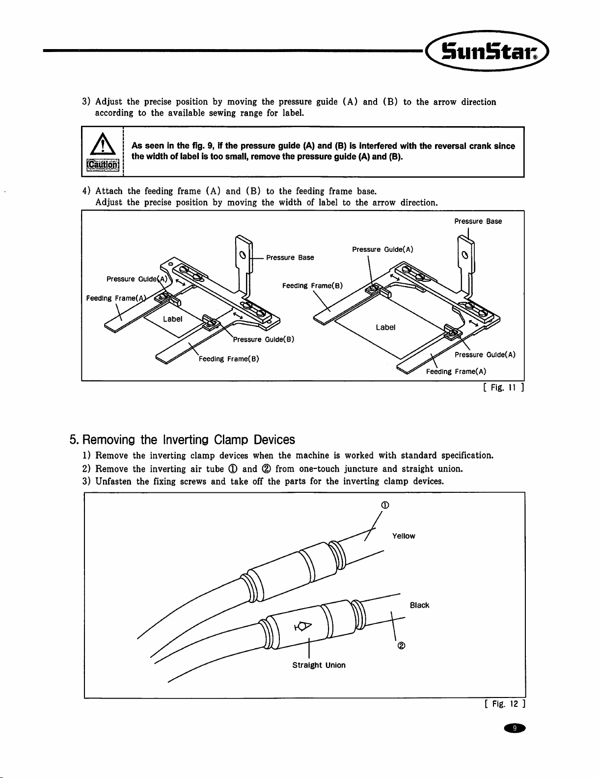
3)
Adjust
according
the
precise
to
position
the
available
by
moving
sewing
the
range
pressure
for
label.
guide
(A)
and
(B)
to
the
arrow
direction
f\ I As
A
4)
Attach
Adjust
Pressure
Feeding
I the
the
the
GuideCA)^
Frame(
seen
in
the
width
of
label
feeding
precise
frame
position
fig.
9,
if
is
too
(A)
by
Feeding
the
pressure
small,
remove
and
(B)
to
moving
Frame(B)
the
Pressure
Pressure
Gulde(B)
guide
(A)
and
the
pressure
the
feeding
width
of
Base
Feeding
Frame(B)
(B)
guide
frame
label
is
interfered
(A)
base.
to
the
Pressure
and
(8).
arrow
Guide(A)
Labe
with
direction.
the
reversal
Pressure
Pressure
Feeding
Frame(A)
crank
since
Base
Gulde(A)
[
Fig.
11
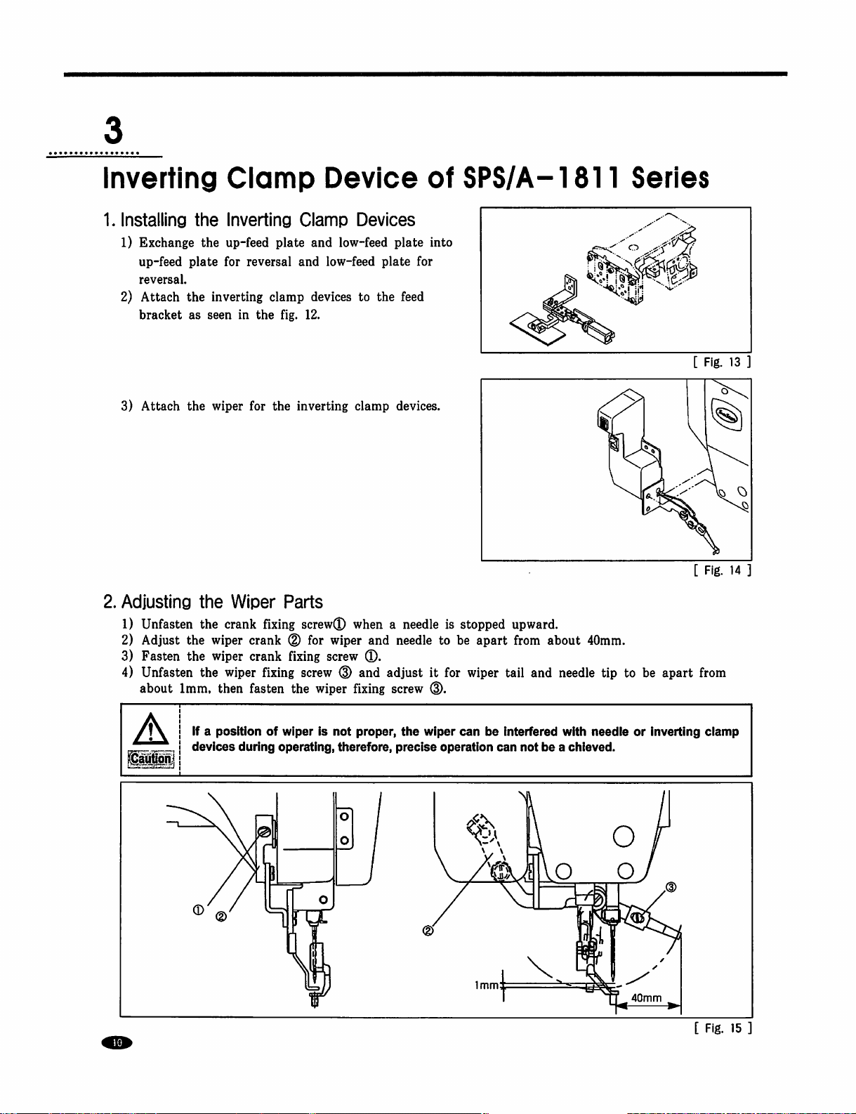
5.
Removing
1)
Remove
2)
Remove
3)
Unfasten
the
Inverting
the
inverting
the
inverting
the fixing
clamp
air
tube
screws
and
—
Clamp
devices
(D
and
take
Devices
when
the
(D
from
off
the
parts
machine
is
one-touch
for
the
straight
Union
worked
juncture
inverting
with
and
clamp
/
standard
straight
devices.
Yellow
Black
specification.
union.
[
Fig.
12
Inverting
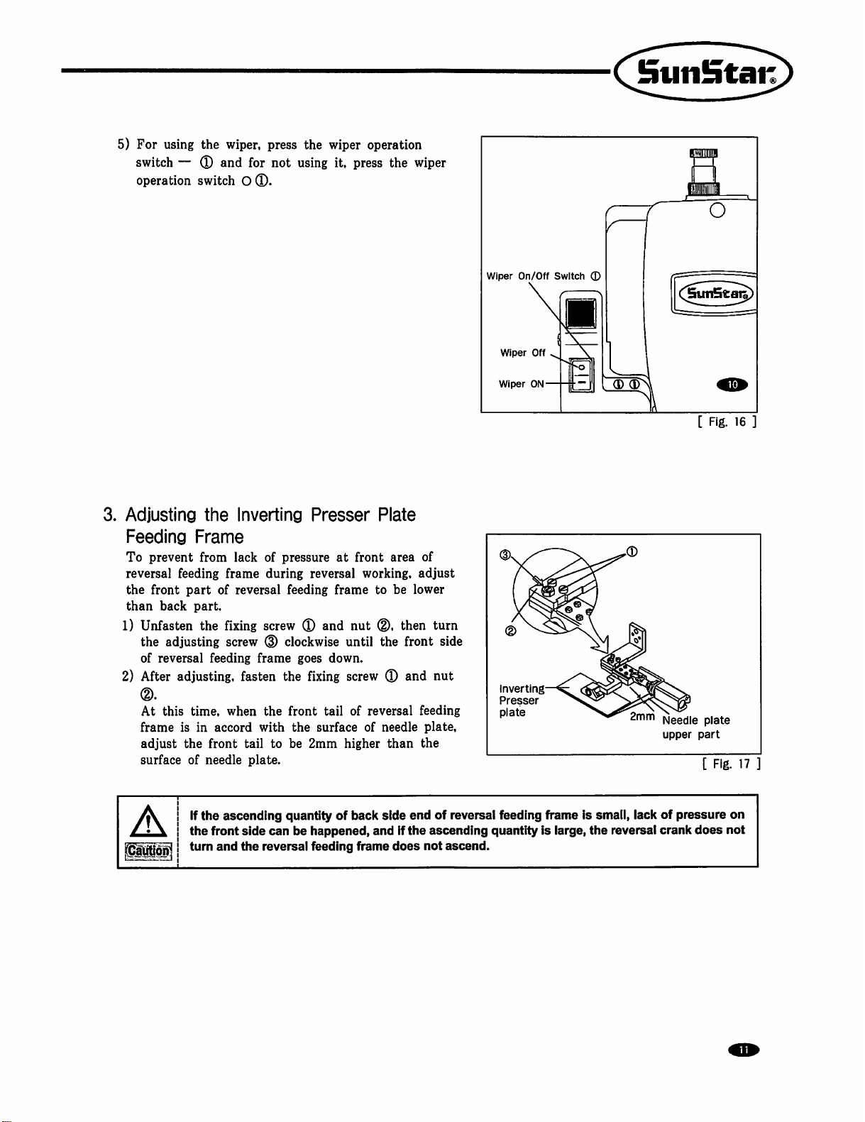
1.
Installing
1)
Exchange
up-feed
reversal.
2)
Attach
bracket
3)
Attach
Clamp
the
Inverting
the
up-feed
plate
for
the
inverting
as
seen
the
wiper
reversal
in
for
plate
clamp
the
fig.
the
Device
Clamp
and
and
devices
12.
inverting
Devices
low-feed
low-feed
to
clamp
plate
plate
the
feed
devices.
of
into
for
SPS/A-1811
Series
[
Fig.
[
Fig.
13
14
2.
Adjusting
1)
Unfasten
2)
Adjust
3)
Fasten
4)
Unfasten
about
A
the
Wiper
the
crank fixing
the
wiper
the
wiper
the
wiper
1mm,
then
If a position
devices
during
Parts
screw®
crank ® for
crank
fixing
screw
fixing
screw
fasten
the
wiper
of
wiper
is
operating,
when a needle
wiper
and
needle
®.
(D
and
adjust
fixing
screw
not
proper,
therefore,
the wiper
precise
is
stopped
to
be
it
for
wiper
(D.
can
operation
upward.
apart
from
tail
be
interfered
can
about
and
needle
with
not
be a chieved.
40mm.
tip
needie
to
be
apart
or
inverting
40mm
from
ciamp
[
Fig.
15
5)
For
switch — ®
operation
3.
Adjusting
Feeding
To
prevent
reversal
the
front
than
back
1)
Unfasten
the
of
reversal
2)
After
(D.
At
this
frame
adjust
surface
using
the
wiper,
and
switch O ®.
the
Frame
from
lack
feeding
adjusting
adjusting,
is
part
part.
the
feeding
time,
in
the
front
of
needle
frame
of
fixing
screw
when
accord
press
the
for
not
using
Inverting
of
during
reversal
Presser
pressure
reversal
feeding
screw ® and
(D
clockwise
frame
goes
fasten
the
with
tail
to
plate.
the
fixing
front
the
be
2mm
surface
wiper
operation
it,
press
Plate
at
front
working,
frame
down.
tail
to
nut
(D.
until
the
screw ® and
of
reversal
of
needle
higher
the
area
be
lower
then
front
than
wiper
of
adjust
turn
side
nut
feeding
plate,
the
Wiper
On/Off
Wiper
Wiper
ON-
(D
^<2^
Inverting—
Presser
plate
Off
Switch
■
c;
©
C[5un5t^)
(D
(D
[
Fig.
16
]
Needle
plate
upper
part
[
Fig.
17
If
the
aunon
ascending
the
front
turn
and
side
the
quantity
can
be
happened,
reversal
feeding
of
back
and
frame
side
end
If
the
does
of
reversal
ascending
not
ascend.
feeding
quantity
frame
is
is
smali,
large,
the
lack
of
reversal
crank
pressure
does
on
not
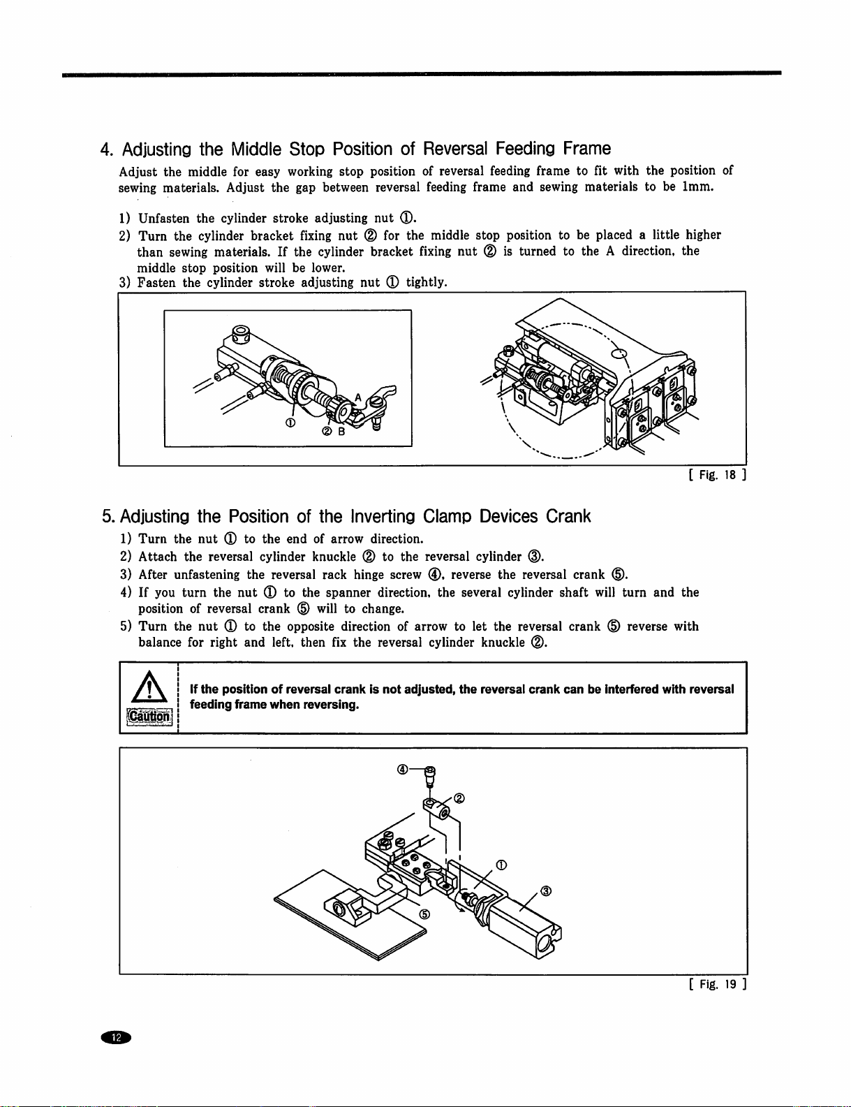
4.
Adjusting
Adjust
sewing
1)
2)
the
materials.
Unfasten
Turn
than
middle
3)
Fasten
5.
Adjusting
1)
Turn
2)
Attach
3)
After
4)
If
you
position
5)
Turn
balance
the
Middle
middle
the
sewing
stop
the
the
the
unfastening
turn
of
the
for
for
Adjust
the
cylinder
cylinder
bracket
materials.
position
cylinder
the
Position
nut ® to
reversal
the
the
nut ® to
reversal
nut ® to
right
and
Stop
easy
working
the
gap
stroke
will
stroke
the
cylinder
reversal
crank
the
left,
adjusting
fixing
If
the
be
lower.
adjusting
of
end
of
knuckle
the
d)
opposite
then
Position
stop
position
between
cylinder
the
arrow
rack
spanner
will
fix
reversal
nut
nut
(D
for
bracket
nut
(D
Inverting
direction.
(D
to
hinge
direction,
to
change.
direction
the
reversal
of
Reversal
of
feeding
®.
the
middle
fixing
tightly.
Clamp
the
reversal
screw
(D,
of
arrow
cylinder
Feeding
reversal
the
feeding
frame
stop
nut ® is
Devices
cylinder
reverse
several
to
let
the
knuckle
frame
and
sewing
position
turned
Crank
the
reversal
cylinder
reversal
(D.
Frame
to
fit
with
the
materials
to
be
placed a little
to
the A direction,
crank
shaft
will
crank
d).
turn
d)
reverse
to
and
position
be
1mm.
higher
the
[
Fig.
the
with
of
18
If
the
position
feeding
frame
of
reversal
when
reversing.
crank
is
not
adjusted,
the
reversal
crank
can
be
interfered
with
reversal
[
Fig.
19
]
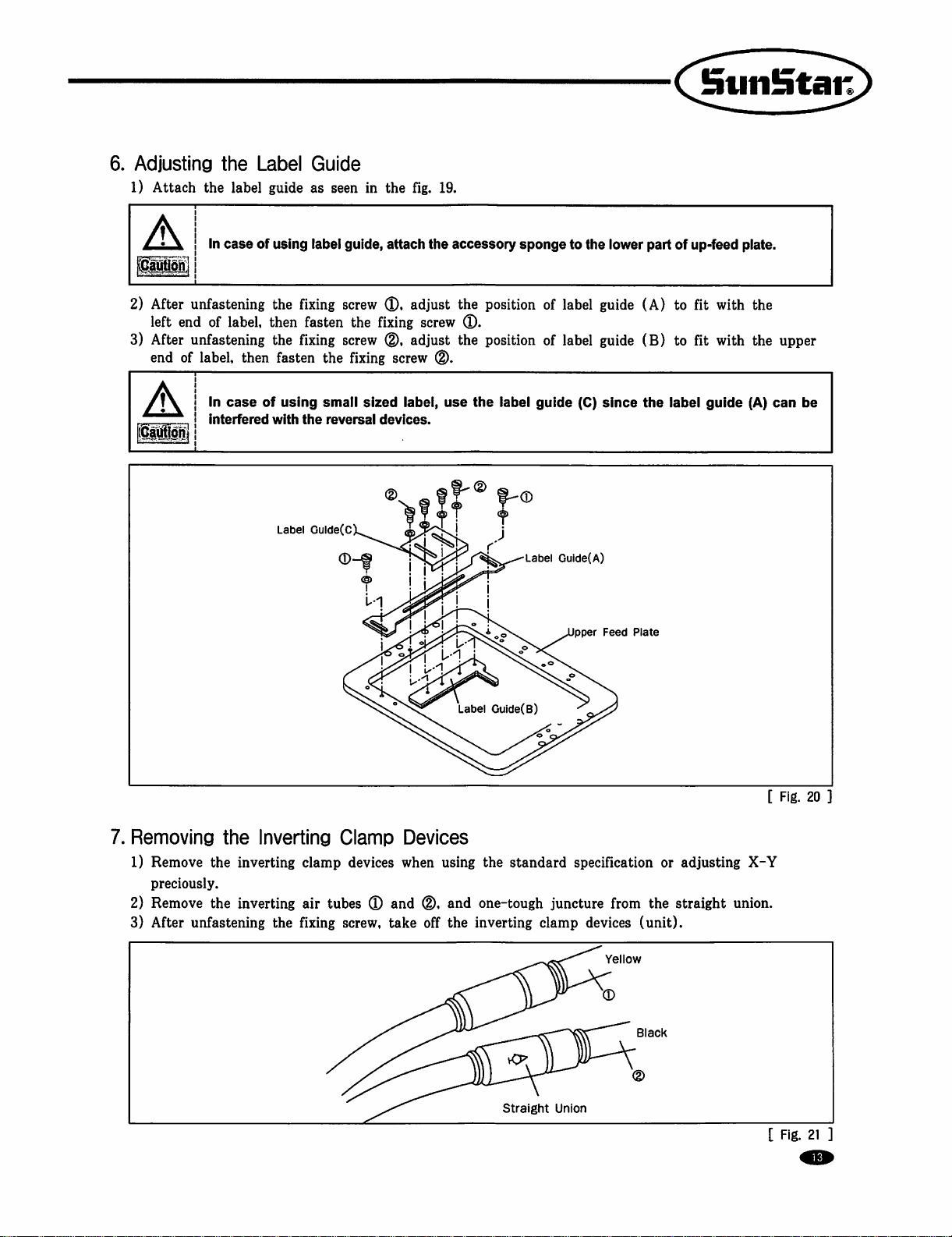
6.
Adjusting
1)
Attach
A
ICaliW]
2)
After
left
3)
After
end
A
the
Label
the
label
guide
In
case
of
unfastening
end
of
label,
then
unfastening
of
label,
then
In
case
of
interfered
Guide
as
using
label
the
fixing
fasten
the
fixing
fasten
using
with
the
Label
Gulde(C
seen
guide,
screw
the
screw
the
fixing
small
sized
reversal
in
the
attach
(D.
fixing
0,
screw
label,
devices.
fig.
19.
the
accessory
adjust
the
screw
0.
adjust
the
0.
use
sponge
position
position
the
label
guide
to
of
label
of
label
the
(C)
lower
guide
(A)
guide
(B)
since
the
C^^nSta^
part
of
up-feed
to
fit
to fit
iabel
plate.
with
with
guide
the
the
(A)
upper
can
be
7.
Removing
1)
Remove
preciously.
2)
Remove
3)
After
the
Inverting
the
inverting
the
inverting
unfastening
the
Clamp
clamp
air
fixing
devices
tubes ® and
screw,
Devices
when
(D,
take
off
Label
Guide(B)
using
the
and
one-tough
the
inverting
Label
Guide(A)
pper
standard
specification
juncture
clamp
Feed
Plate
from
the
devices
Ye
ow
(unit).
or
adjusting
straight
[
X-Y
union.
Fig.
20
Straight
Union
B
ack
[
Fig.
21
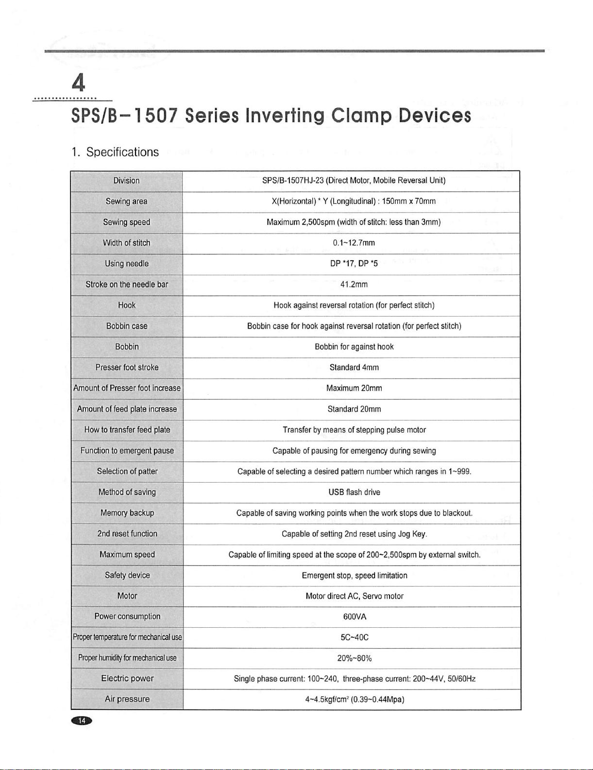
SPS/B-1507
1.
Specifications
Series
Inverting
Clamp
Devices
Sewing
Stroke
Presser
Amount
of
Amount
How
to
Function
Sewing
area
speed
Width
of
stitch
Using
needle
on
the
needle
Bobbin
case
foot
Presser
of
feed
plate
transfer
to
emergent
stroke
foot
increase
increase
feed
piate
pause
bar
SPS/B-1507HJ-23
X(Horizontal) * Y
Maximum
Bobbin
Hook
case
2,500spm
against
for
hook
Transfer
Capable
of
(Direct
Motor,
(Longitudinal):
(width
of
DP
*17,
DP
reversal
rotation
against
reversal
Bobbin
for
against
Standard
Maximum
Standard
by
means
pausing
4mm
20mm
20mm
of
stepping
for
emergency
Mobile
Reversal
150mm x 70mm
stitch:
less
*5
(for
perfect
rotation
hook
puise
during
than
stitch)
(for
perfect
motor
sewing
Unit)
3mm)
stitch)
Selection
Method
Memory
2nd
Maximum
Safety
Power
Proper
temperature
Proper
humidity
Electric
of
patter
of
saving
backup
reset
function
speed
device
consumption
for
mechanical
for
mechanicai
power
use
use
Capable
Capable
Capable
of
Single
phase
of
selecting a desired
of
saving
working
Capable
limiting
of
speed
setting
at
the
Emergent
Motor
current:
100-240,
4-4.5kgf/cm^
pattern
number
USB
flash
drive
points
when
2nd
reset
scope
of
200-2,500spm
stop,
speed
direct
AC,
Servo
5C-40C
20%-80%
three-phase
(0.39-0.44Mpa)
which
the
work
stops
using
Jog
limitation
motor
current:
ranges
in 1 ~999.
due
to
blackout.
Key.
by
external
200-44V,
50/60H2
switch.
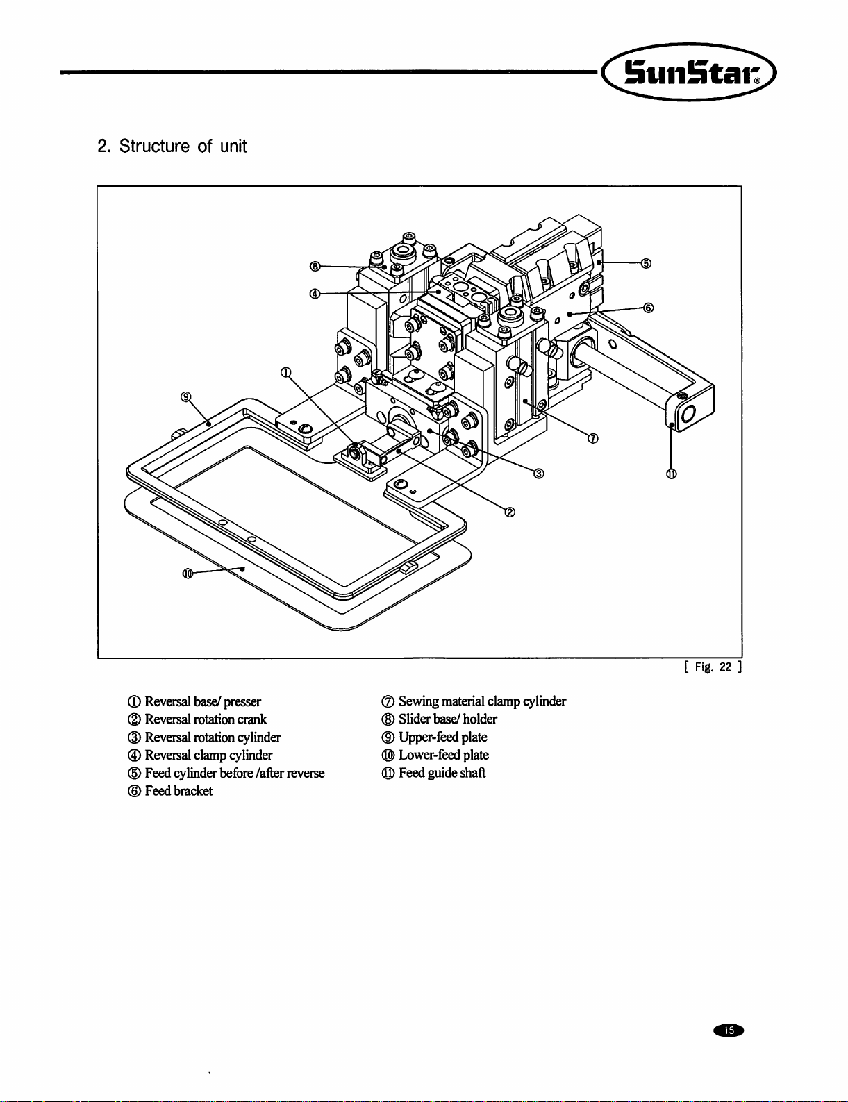
2.
Structure
of
unit
®
Reversal
(D
Reversal
(D
Reversal
®
Reversal
(D
Feed
(©
Feed
base/
presser
rotation
rotation
clamp
cylinder
bracket
before
crank
cylinder
Under
/after
reverse
®
Sewing
(H)
Slider
base/
(D
Upper-feed
®
Lower-feed
(Q)
Feed
guide
material
clamp
holder
plate
plate
shaft
cylinder
[
Fig.
22
3.
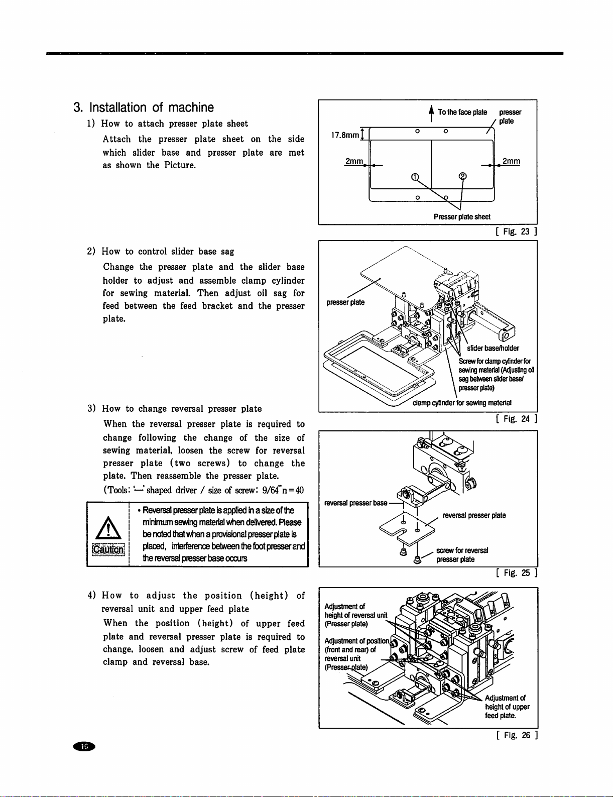
Installation
1)
How
to
Attach
which
as
shown
2)
How
to
Change
holder
for
sewing
feed
between
plate.
of
attach
the
presser
slider
base
the
Picture.
control
the
presser
to
adjust
material.
the
machine
presser
slider
plate
and
plate
and
feed
plate
base
assemble
Then
bracket
sheet
sheet
presser
sag
and
the
adjust
and
on
plate
slider
clamp
oil
the
the
side
are
met
base
cylinder
sag
for
presser
17.8mm|_
2mm^
presser
plate
o
A
To
the
'
o
Presser
face
plate
plate
sheet
slider
Screw
for
presser
/ plate
2mm
[
Fig.
base/holder
damp
cylinder
23
for
3)
How
to
change
When
the
reversal
change
sewing
presser
plate.
following
material,
plate
Then
(Tools: — shaped
Reversal
minimum
be
placed,
the
4)
How
to
adjust
reversal
When
plate
change,
clamp
unit
the
and
loosen
and
reversal
reversal
presser
the
loosen
(two
screws)
reassemble
driver / size
presser
plate
sevwng
material
noted
that
when a provisional
'(nterference
reversal
presser
the
and
upper
position
reversal
presser
and
(height)
adjust
base.
presser
change
the
plate
plate
of
screw
is
to
the
presser
of
screw:
Is
appl'ed
when
delivered.
presser
between
the
base
occurs
position
feed
(height)
plate
of
plate
is
screw
required
the
size
for
reversal
change
plate.
9/64"n=40
in a size
of
Rease
plate
toot
presser
upper
required
of
feed
to
of
the
the
is
and
of
feed
to
plate
reversal
presser
base
Adjustment
height
(Presser
Adjustment
(front
reversal
(Presse
of
of
reversal
plate)
of
and
rear)
unit
position^
of
unit
damp
cylinder
for
sewing
matenal
[
Fig.
24
—
J
1 ,
screw
presser
reversal
presser
for
reversal
plate
plate
[
Fig.
25
Adjustment
height
feed
plate.
[
Fig.
of
of
upper
26
 Loading...