

SunStar SPS/B-1306 SERIES, SPS/A-1306 SERIES, SPS/B-1507 SERIES, SPS/A-1507 SERIES, SPS/B-1310 SERIES User Manual
...
EElleeccttrroonniiccaallllyy CCoonnttrroolllleedd
PPaatttteerrnn SSeewwiinngg MMaacchhiinnee
((MMeecchhaanniiccaall PPaarrtt))
USER
’’
S
MANUAL
SPS/B-1306 SERIES
SPS/A-1306 SERIES
SPS/B-1507 SERIES
SPS/A-1507 SERIES
SPS/B-1310 SERIES
SPS/A-1310 SERIES
1) FOR AT MOST USE WITH EASINESS,
PLEASE CERTAINLY READ THIS MANUAL
BEFORE STARTING USE.
2) KEEP THIS MANUAL IN SAFE PLACE
FOR REFERENCE WHEN THE MACHINE
BREAKS DOWN.
MME-041129
SSUUNNSSTTAARR MMAACCHHIINNEERRYY CCOO..,, LLTTDD..
SSUUNNSSTTAARR MMAACCHHIINNEERRYY CCOO..,, LLTTDD..

Best Quality
Best Price
Best Service
SSUUNNSSTTAARR MMAACCHHIINNEERRYY CCOO..,, LLTTDD..
R
1.
Thank you for purchasing our product. Based on the rich expertise and
experience accumulated in industrial sewing machine production, SUNSTAR
will manufacture industrial sewing machines, which deliver more diverse
functions, high performance, powerful operation, enhanced durability, and
more sophisticated design to meet a number of user’s needs.
2. Please read this user’s manual thoroughly before using the machine. Make
sure to properly use the machine to enjoy its full performance.
3. The specifications of the machine are subject to change, aimed to enhance
product performance, without prior notice.
4.
This product is designed, manufactured, and sold as an industrial sewing
machine. It should not be used for other than industrial purpose.
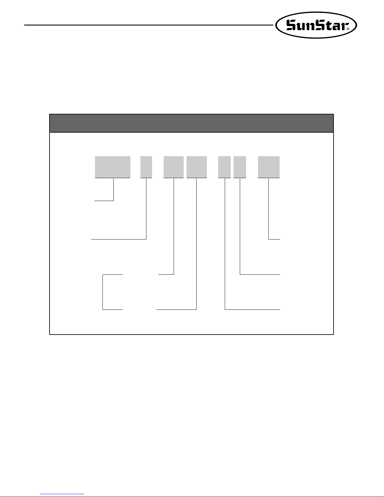
Organization of the Pattern S/M Model
Series
A: Motor belt-type
B: Motor direct drive-type
SunStar
Pattern
System
Sewing Area
SPS/B-1306-H S-10
X : 130mm
Y : 60mm
Feeding Frame
Type
Stitch Type
Material Type
Pattern Model
A : Belt Type
H : Drive Type
Sewing Area
1306 : X(130mm), Y(60mm)
1507 : X(150mm), Y(70mm)
1310 : X(130mm), Y(100mm)
1811 : X(180mm), Y(110mm)
2516 : X(250mm), Y(160mm)
5030 : X(500mm), Y(300mm)
ApplicationSewing Area
G:General Material
H:Heavy Material
Stitch Type
S:Standard Stitch
P:Perfect Stich
Feeding Frame Type
10 : Magnet-Driven Feeding Frame
20 : Pneumatic Monolithic Feeding Frame
21 : Pneumatic Monolithic Feeding Frame with Two Step
Stroke Device
22 : Pneumatic Separately-Driven Feeding Frame
(22-1 : Pneumatic Separately-Driven Feeding Frame wiht
Two Step Stroke Device
23 :Pneumatic Separately-Driven Feeding Frame with
Inverting Clamp Device

CONTENT
1. Machine Safety Regulations 6
1) Machine Transportation 6
2) Machine Installation 6
3) Machine Repair 6
4) Machine Operation 7
5) Devices for Safety 7
6) Caution Mark Position 8
7) Contents of Marks 8
2. Specifications of the Machine 9
3. Structure of the Machine 10
1) Names of each parts of the machine 10
2) Inside structure of control box 11
4. Installation of the Machine 13
1) Environment for machine installation 13
2) Electric installment conditions 13
3) How to install the table safety 13
4) The assembly of peripheral parts 17
5. Preparations Before Operating The Machine 20
1) How to supply oil 20
2) How to install the needle bar 21
3) How to thread the upper thread 22
4) Threading the lower thread 22
5) How to take the bobbin case on and off 23
6) How to adjust the tension of the upper thread and the lower thread 23
7) How to wind the lower thread 24
8) Adjusting the height of the presser foot 24
9) Disposing the waste oil 24
10) Model of transformer by voltage and setup of voltage 25
11) Caution when using the floppy disks 26
6. How to Repair the Machine 27
1) Adjusting the height of the needle bar 27
2) Adjusting the needle and the shuttle 27
3) Adjusting the lower shaft gear and the rocking shaft gear 28
4) Adjusting the spring on the upper side of the shuttle 28
5) Adjusting the height of the feed plate 29
6) Adjusting the presser foot devices 29
7) Adjusting the parts for the presser plate 31
8) Adjusting the parts for thread release 31
9) Adjusting the parts for the wiper 33
10) Adjusting the X-Y parts 34
11) Adjusting the trimming parts 35
12) Adjusting the main thread control device 38
13) Adjusting the upper thread detecting device 38
14) Adjusting the hand pulley device 38
15) Adjusting the winding device 39
16) How to Set the Position of Syncro (A Series) 39
17) Mounting the direct motor and adjusting method (B Series) 40
18) How to set the original point of X-Y 41
19) Exchanging the Fuse 42

7. Causes of Break-Down and Throubleshooting 43
8. SPS/B(A)-1306(1507)-GS-10 45
1) Machine specifications 45
2) How to thread the upper thread 45
9. SPS/B(A)-1306(1507)-HP(GP)-
46
1) Machine specifications 46
2) How to attach the needle 47
3) How to hook the upper thread 47
4) How to hook the lower thread 47
5) Adjusting the spring on the upper side of the shuttle 48
6) Adjusting the moving knife and the fixed knife 48
10.
SPS/B(A)-1306(1507)-HS(GS)-20(21, 22-1, 22, 23) and SPS/B(A)-1310-HS(GS)-20(22)
49
1) Machine specifications 49
2) How to attach the parts for air pressure control 50
3) How to adjust the air pressure 50
4) Attaching the pressure plate sheet and adjusting the height of the slider base 50
5) How to adjust the up and down movement of the upper feed plate 51
6) How to use the manual pedal switch 52
7) Air system ciruit diagrams 54
8) Setting and Adjustment of SPS/B(A)-1310 58
11. Drawing of Table 60

6
11
MACHINE SAFETY REGULATIONS
Safety instruction on this manual are defined as Danger, Warning and Notice.
If you do not keep the instructoins, physical injury on the human body and machine damage might be occurred.
: This indication should be observed definitely. If not, danger could be happen during the installation,
conveyance and maintenance of machines.
: When you keep this indication, injury from the machine can be prevented.
: When you keep this indication, error on the machine can be prevented.
Danger
Warning
Notice
Those in charge of transporting the machine should know the safety regulations very
well. The following indications should be followed when the machine is being
transported.
ⓐ More than 2 people must transport the machine.
ⓑ To prevent accidents from occurring during transportation, wipe off the oil on the
machine well.
1-1) Machine
Transportation
Danger
The machine may not work well or breakdown if installed in certain places, Install the
machine where the following qualifications agree.
ⓐ Remove the package and wrappings starting from the top. Take special notice on
the nails on the wooden boxes.
ⓑ Dust and moisture stains and rusts the machine. Install an airconditioner and clean
the machine regularly.
ⓒ Keep the machine out of the sun.
ⓓ Leave sufficient space of more than 50cm behind, and on the right and left side of
the machine for repairing.
ⓔ Do not operate in explosive atmospheres. To avoid explosion, do not operate this
machine in an explosive atmosphere including a place where quantities of erosol
spray product are being used or where oxygen is being administered unless it has
been specifically certified for such operation.
ⓕ The machines were not provided with a local lighting due to the feature of machine.
Therefore the illumination of the working area must be fulfilled by end user.
[ Reference ] Details for machine installation are described in 4. Machine Installation.
1-2) Machine
Installation
Notice
When the machine needs to be repaired, only the assigned troubleshooting engineer
educated at the company should take charge.
ⓐ Before cleaning or repairing the machine, Turn off the main power and wait
4 minutes till the machine is completely out of power.
ⓑ Not any of the machine specifications or parts should be changed without consulting
the company. Such changes may make the operation dangerous.
ⓒ Spare parts producted by the company should only be used for replacements.
ⓓ Put all the safety covers back on after the machine has been repaired.
1-3)Machine Repair
Danger
7
SPS/B(A)-1306(1507, 1310) Series are made for industrial use to perform pattern
sewing for fabrics or its similar materials. Please observe the following principles.
ⓐ Read the manual to understand on the operation of machine perfectly.
ⓑ Wear suitable clothes and cap for safe operation.
ⓒ During operation, don’t make you body close to operating part of machine such as
needle, hook, take-up lever or pulley.
ⓓ Do not remove a safety plate and covers during operation
ⓔ Be sure the grounding lines in connected.
ⓕ Before opening electricity box such as control box, cut off the supply of electricity
and confirm if the switch is “off”.
ⓖ When inserting thread into a needle or before inspecting after sewing, be sure the
machine is stopped.
ⓗ Do not turn on the power during pedaling.
ⓘ Do not use several motor per a electric outlet.
ⓙ Install the machine apart from noise occurrence area such as high frequency
welding machines as far as possible.
ⓚ Be careful-When the upper feed plate comes down to press. Otherwise, the finger or
hand hight be hurt at smacking.
1-4)Machine
Operation
Warning
Notice
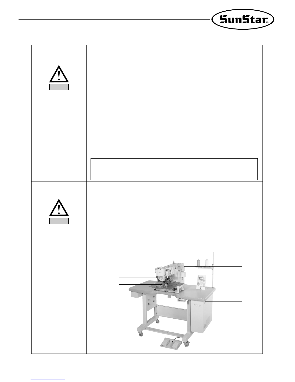
[ Warning ]
Belt will crush or amputate finger or hand, keep cover in place before operating, turn off
power before inspecting or adjusting.
ⓐ Safety label : It describes cautions during operating the machine.
ⓑ Thread take-up lever : It prevents from any contact between body and take-up lever.
ⓒ Servo motor cover : It prevents from insertion of hands, feet or clothes by motor and
Y-drive shaft.
ⓓ Step motor cover : It prevents from accidents during rotation of step motors.
ⓔ Label for specification of power : It describes cautions for safety to protect against
electric shock during rotating the motors.
ⓕ Safety plate : It protects eyes against needle breaks.
ⓖ Finger guard : It prevent from contacts between a finger and needle.
1-5)Devices for
Safety
ⓐⓑ
ⓕ
ⓖ
ⓒ
ⓓ
ⓐ
ⓔ
8
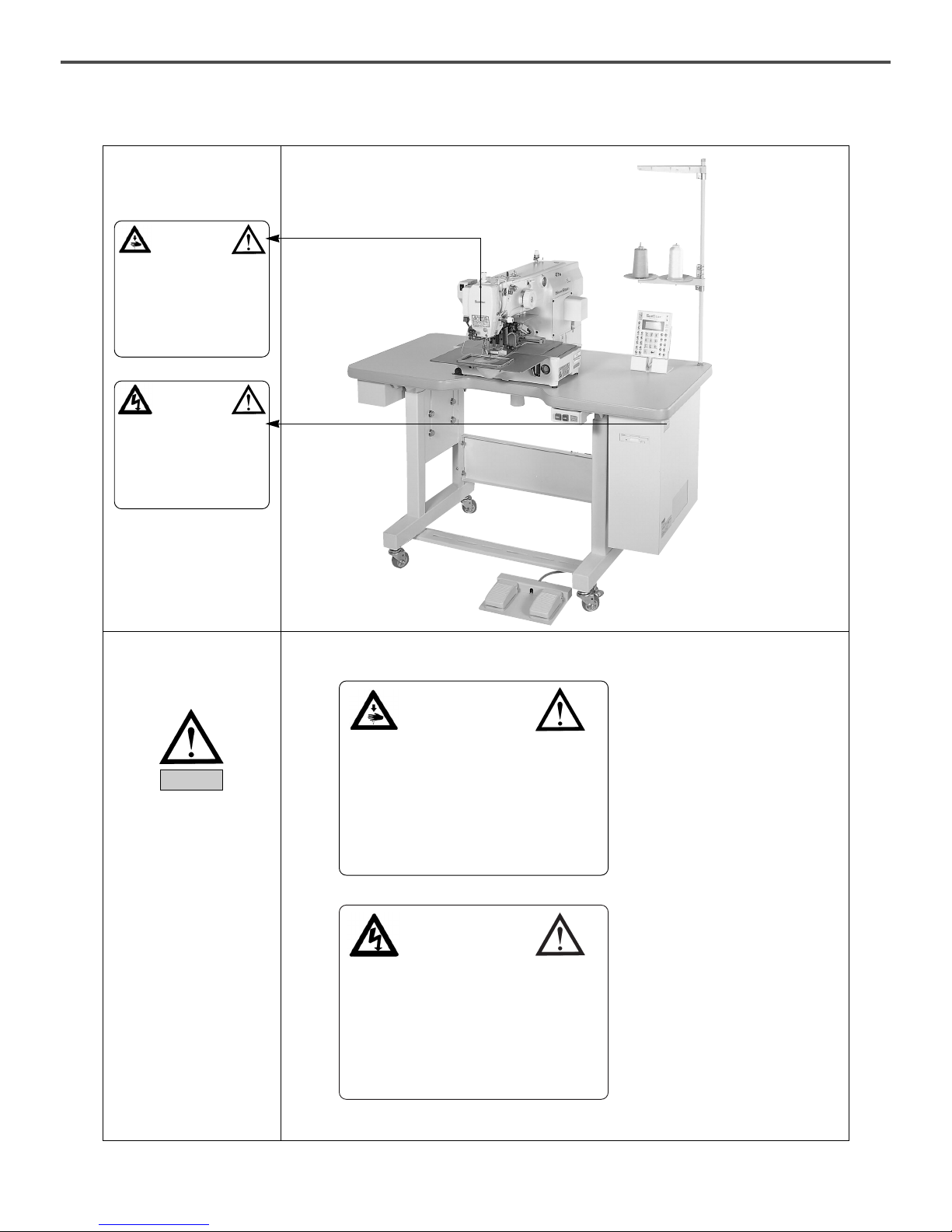
1-6)Caution Mark
Position
Caution
1)
2)
1-7) Contents of Marks
Warning
CAUTION
경고
Do not operate without finger guard
and safety devices. Before threading,
changing bobbin and needle, cleaning
etc. switch off main switch.
손가락 보호대와 안전장치 없이 작동하지 마
십시오.
실, 보빈, 바늘교환시나 청소전에는 반드시
주전원의 스위치를 꺼 주십시오.
CAUTION
경고
Hazardous voltage will cause injury.
Be sure to wait at least 360 seconds
before opening this cover after turn
off main switch and unplug a power
cord.
고압 전류에 의해 감전될 수 있으므로 커버
를 열 때는 전원을 내리고 전원 플러그를 뽑
고 나서 360초간 기다린 후 여십시오.
CAUTION
경고
Do not operate without finger guard and
safety devices. Before threading, changing
bobbin and needle, cleaning etc. switch off
main switch.
손가락 보호대와 안전장치 없이 작동하지
마십시오.
실, 보빈, 바늘교환시나 청소전에는 반드시 주
전원의 스위치를 꺼 주십시오.
CAUTION
경고
Hazardous voltage will cause injury.
Be sure to wait at least 360 seconds before
opening this cover after turn off main switch
and unplug a power cord.
고압 전류에 의해 감전될 수 있으므로 커버를
열 때는 전원을 내리고 전원 플러그를 뽑고 나
서 360초간 기다린 후 여십시오.
Caution mark is attached on the machine for safety.
When you operate the machine, observe the directions on the mark.
Position of Warning Mark
9
22
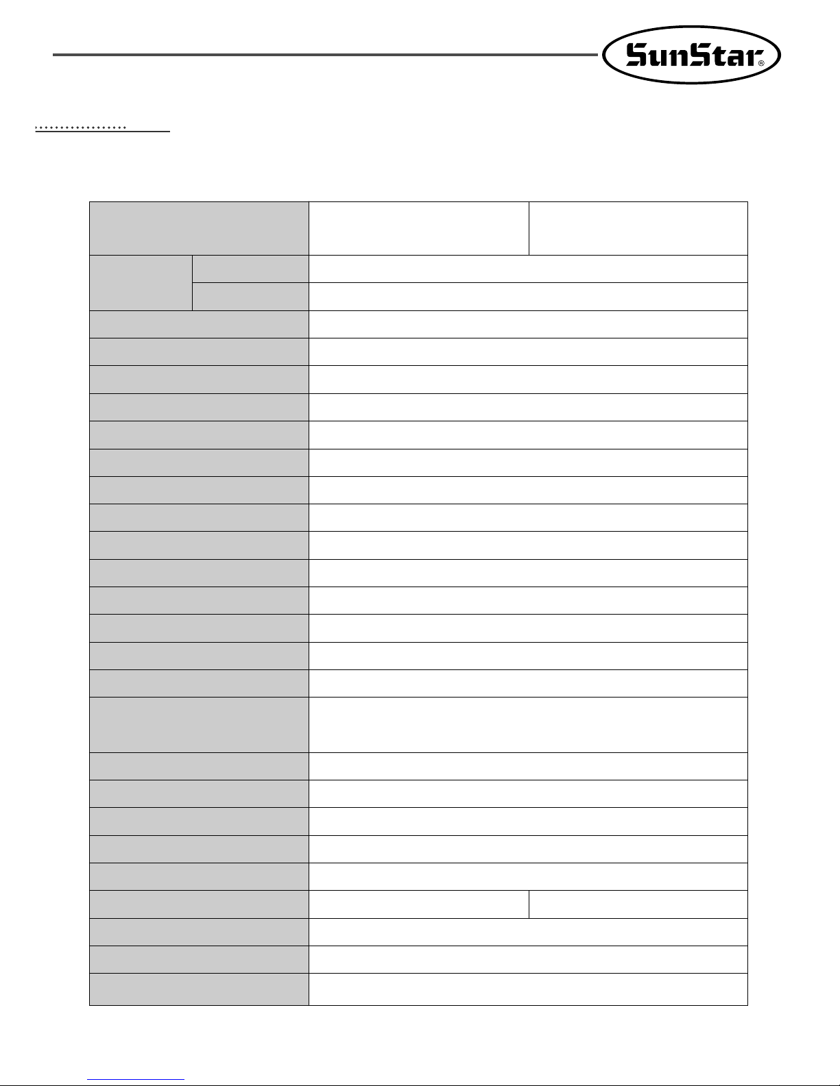
SPECIFICATIONS OF THE MACHINE
Series type
Sewing Area
1306
1507
Sewing Speed
Stitch Length
Needle
Needle Bar Stroke
Hook
Bobbin Case
Bobbin
Presser Foot Stroke
Lifting Amount of Presser Foot
Lifting Amount of Feeding Frame
Feeding System
Emergency Stop Function
Pattern Select Function
Memory
2nd Origin Function
Maximum Speed Limit
Number of Patterns
Safety Device
Main Motor
Power Consumption
Recommended Temperature
Recommended Humidity
Power
SPS/B-1306(1507) SPS/A-1306(1507)
(Motor direct drive-type) (Belt drive-type)
X (wide)× Y(length) : 130mm×60mm
X (wide)× Y(length) : 150mm×70mm
Max. 2,500 spm(Stitch Length : 3mm or shorter)
0.1~12.7
DP×17, DP×5
41.2mm
Semi-Rotary Large Shuttle Hook
Bobbin Case for Semi-Rotary Large Shuttle Hook
Bobbin for Large Shuttle Hook
Standard 4mm [ 0.5~10mm ]
Max. 20mm
22mm [ Max. 25mm ]
Feeding by Pulse Motor
Available During Sewing Operation
Pattern No. Can be Selected from No.1 to No.999
3.5″Floppy Diskette (2HD)
Another Origin Point Can be Set by Using Jog Key
The Maximum Speed can be Limited from 200 to 2,500 spm
Max. 691 Patterns / Disk
Emergency Stop Function, Maximum Speed Limit Function
Direct Drive AC Servo Motor
Direct Drive AC Servo Motor 550W Servo Motor
5。C~40。C
20%~80%
1ф : 100~240V, 3ф: 200~440V, 50/60Hz
The Working Point is Stored in the Memory when the
machine stops Abnormally
Memory Backup
10
33
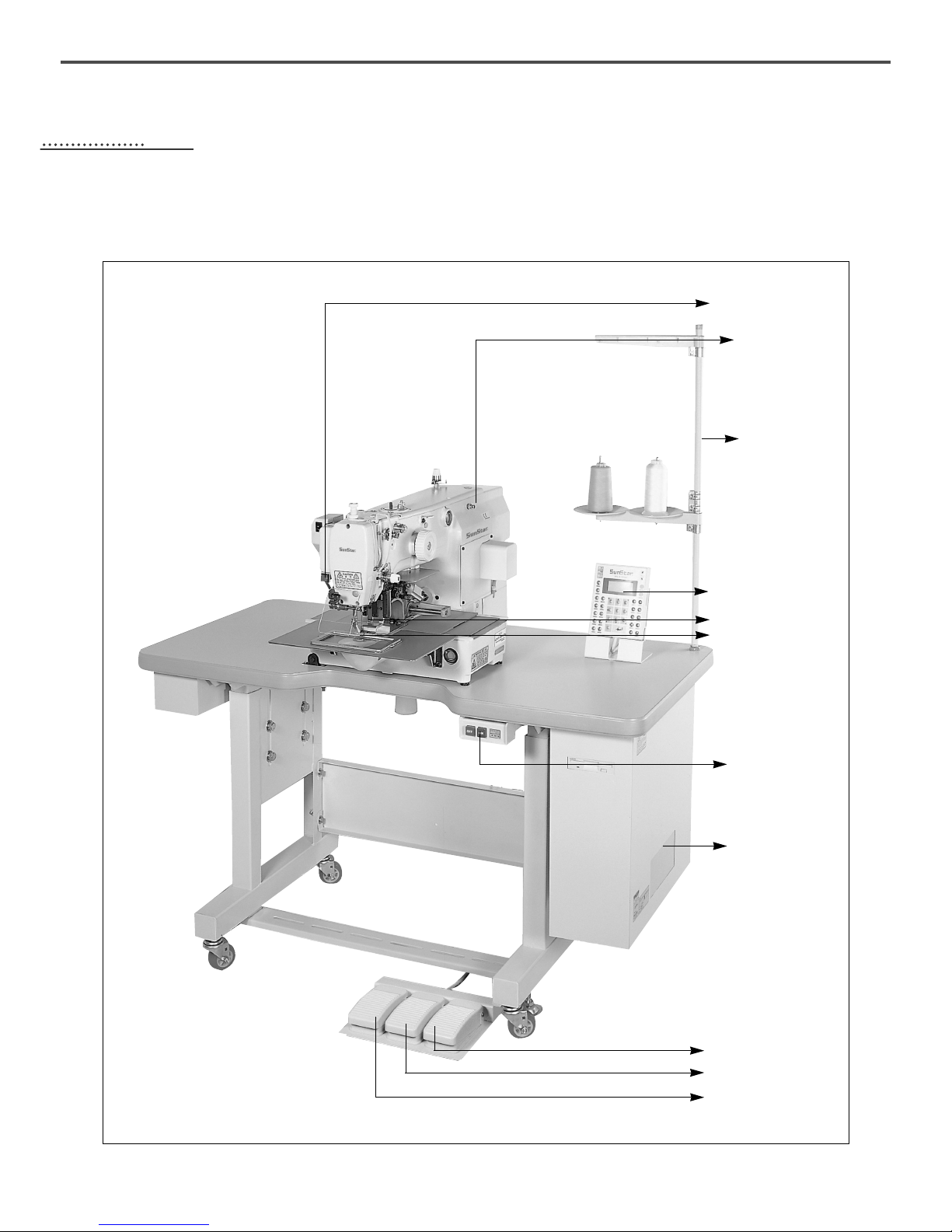
STRUCTURE OF THE MACHINE
1) Names of Each Parts of the Machine
Pause Switch
Arm
Thread Stand
Upper Feed Plate
Lower Feed Plate
Power Switch
Control Box
Upper feed plate pedal
Sewing pedal
Manual pedal
Operation Box
11
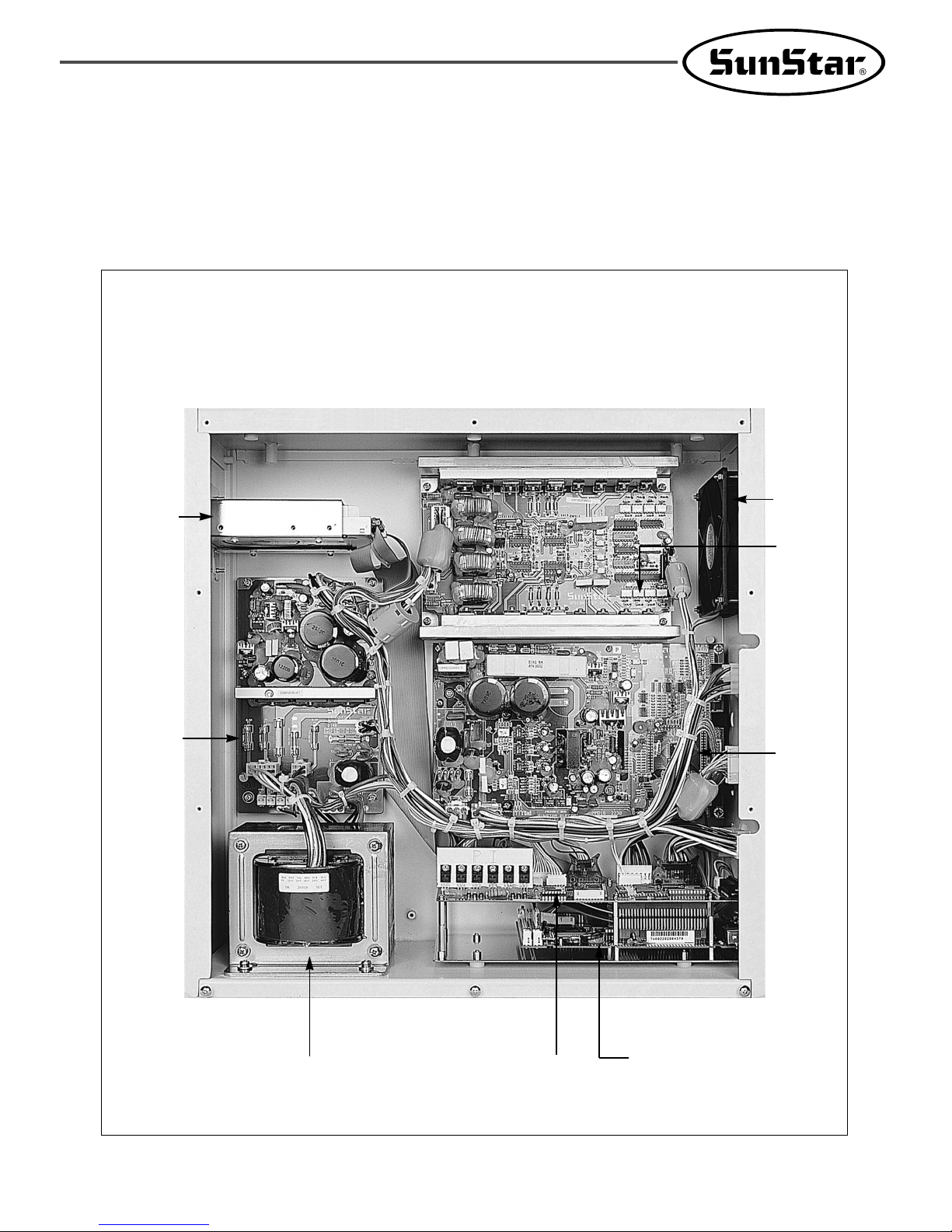
2) Inside Structure of Control Box
① SPS/B-1306(1507, 1310)
Floppy
Disk
Driver
Power
Board
Main
Shaft
Motor
Drive
Board
FAN
Step
Motor
Drive
Board
Transformer
IO Board
386 CPU Board

12
② SPS/A-1306(1507, 1310)
Floppy Disk
Driver
Power
Board
Main Shaft
Motor Drive
Board
FAN
Step Motor
Drive Board
Transformer IO Board
386 CPU Board
13
44
INSTALLATION OF THE MACHINE
1) Environment for Machine Installation
A. Do not use the machine where the voltage is over regular voltage ±10% to prevent accidents.
B. Check the indicated pressure of the devices that use atmospheric pressure such as the air cylinder to prevent any
accidents from occurring.
C. For safe operation of the machine, use the machine under the following conditions.
Surrounding Temperature During Operation : 5℃~40℃
Surrounding Temperature During Maintenance : -10℃~60℃
D. Humidity : Between 20~80%(Relative humidity)
2) Electric Installment Conditions
A. Power Voltage
·The power voltage must be between regular voltage ±10%.
·The frequency of the power should be regular frequency (50/60HZ)±1%.
B. Electromagnetic Wave Noise
Use separate power with strong magnetics or high frequency products, and do not leave the machine near them.
C. Use low voltage when supplements or accessories are being adhered.
D. Be careful not to have water or coffee be spilled into the Controller and Motor.
E. Do not drop the Controller or Motor.
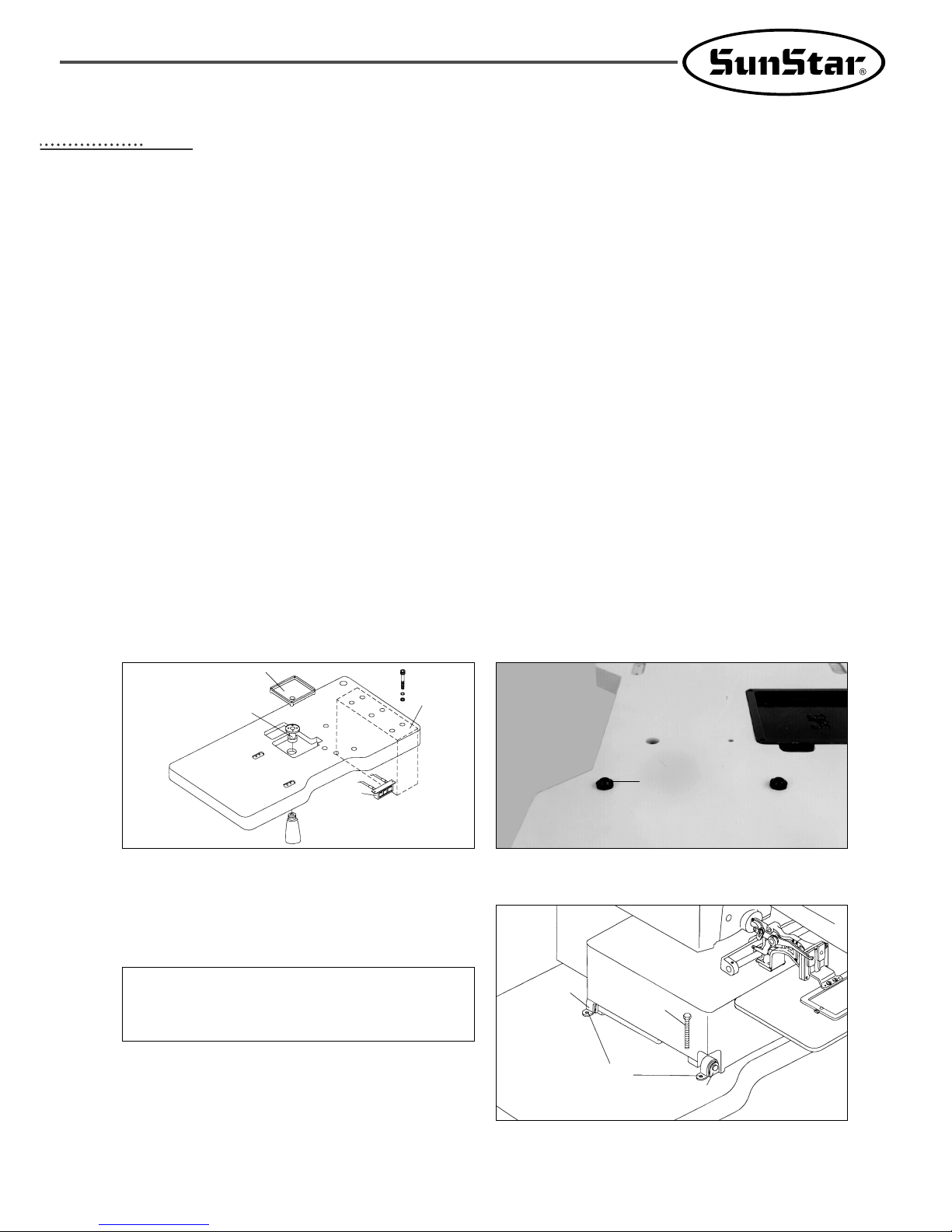
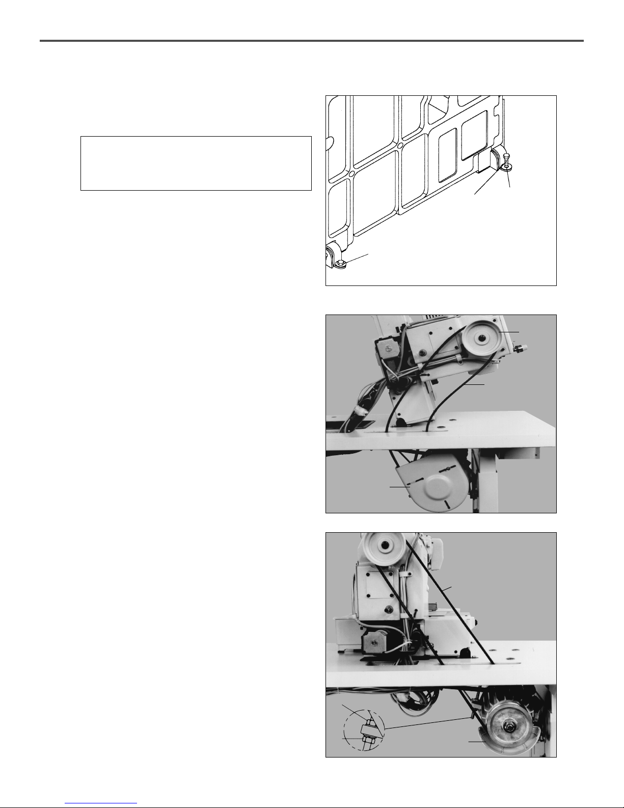
3) How to Install the Table Safety
B. Stick the bed cushion rubber onto the table.
A. Fix the oil tub holder ①, oil holder ②, control box ③
and main switch ④ on the table.
[ Fig. 1 ] [ Fig. 2 ]
C. Add the hinge metal and hinge rubber to the bed.
Then insert the fixing bolt into the hinge metal hole of
point ① and fix the table as shown in the picture.
[ Fig. 3 ]
[ Danger ]
The machine should be carried by more 2 persons for
safety.
Cushion Rubber
Bolt
Hinge
Hinge Rubber
①
①
②
③
④
14
D. Stand the machine as shown in the picture, and then
fix the machine on the table after inserting the fixing
bolts into the hinge metal holes of point ①.
[ Fig. 4 ]
[ Danger ]
Since the machine is not perfectly installed on the table,
extreme care is needed when you make the machine
stand up not to have any accident occurred.
Bolt
①
①
E. Put the “V”-Belt in between the pulley and the motor
while the machine is standing as in the picture.
(A Series)
[ Fig. 5 ]
Pulley
V-Belt
Motor Cover
[ Fig. 6 ]
F. After connecting the “V”-Belt, if the fixing nuts ① and
② are vertically unfastened sufficiently tension
occurs in belt “D”due to the weight of motor “C”.
At this point, first screw in fixing nut ①, then nut ② in
fixing screw tightly.(A Series)
D
C
①
②
15
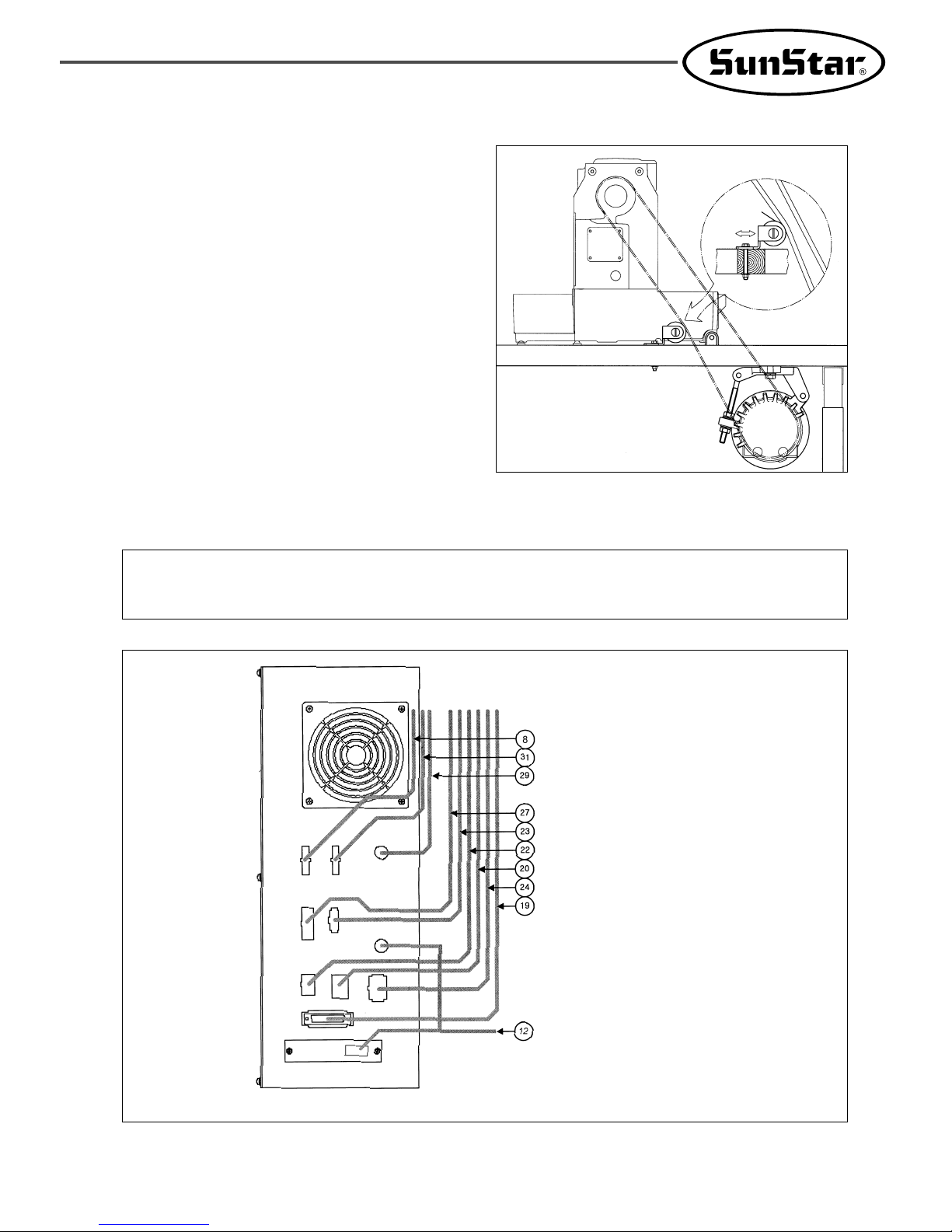
[ Fig. 8 ]
H. Method of Cable Connection
① SPS/B-1306(1507)
Power Supply Cable
Main Motor Cable
Encoder Cable
Step Motor Cable
Air Pressure Control Cable
Pedal Input Cable
Sensor Input Cable
Solenoid Output Cable
Operation Cable
Serial Communication Cable
Green
Backside of Control Box
※ The number in parentheses indicates cable number.
See the Electric Connection Wiring Diagram.
[ Caution ]
① Please turn off the power when you insert or pull out the cable connector.
② Please make sure that cable should not contact to machine parts.
[ Fig. 7 ]
G. As seen in the Fig. adjust the position of idler to
adjust the tension of belt. (A Series)
Idler
16
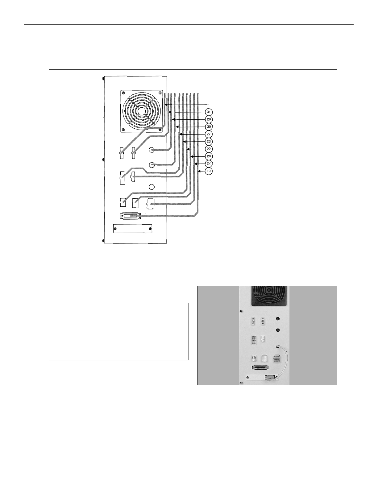
[ Fig. 9 ]
② SPS/A-1306(1507, 1310)
Power Supply Cable
Main Motor Cable
Encoder Cable
Synchro Cable
Step Motor Cable
Air Pressure Control Cable
Pedal Input Cable
Sensor Input Cable
Solenoid Output Cable
Operation Cable
Green
Black
Backside of Control Box
※ The number in parentheses indicates cable number.
See the Electric Connection Wiring Diagram.
[ Fig. 10 ]
I. Connect the connectors of the electric cords from the
machine to the control box.
[ Caution ]
① Hold the connector part to plug in and pull out the
cords.
② Have the power turned off before the cords are
plugged in or pulled out.
③ Make sure the plug cable does not get too close to
the “V”-Belt or other machine supplements.
Control Box
17
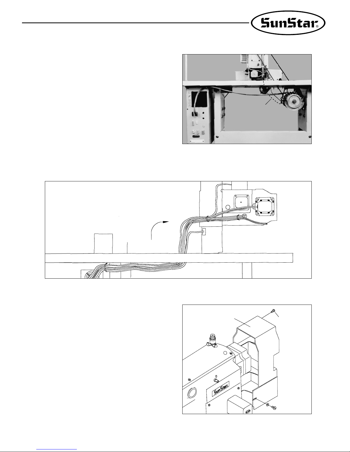
[ Fig. 12 ]
K. After the cable connections between the machine and the control box is finished, fix the cable wiring under the
table as shown in the picture.
(Adjust the length of the wire considering the situation of standing the machine.)
[ Fig. 13 ]
Table
Motor Cover
Fixing Screw
Fixing Screw
4) The Assembly of Peripheral Parts
A. Use the fixing screws to install the motor cover onto
the back of the machine.
(In case of A series, use the fixing screws to install
the belt cover onto the back of the machine.)
[ Fig. 11 ]
J. Be sure to connect the earthing conductor(green)
between the sewing machine and the motor. And
also, connect the earthing conduct or between the
control box and the motor.(A Series)
Conductor
18
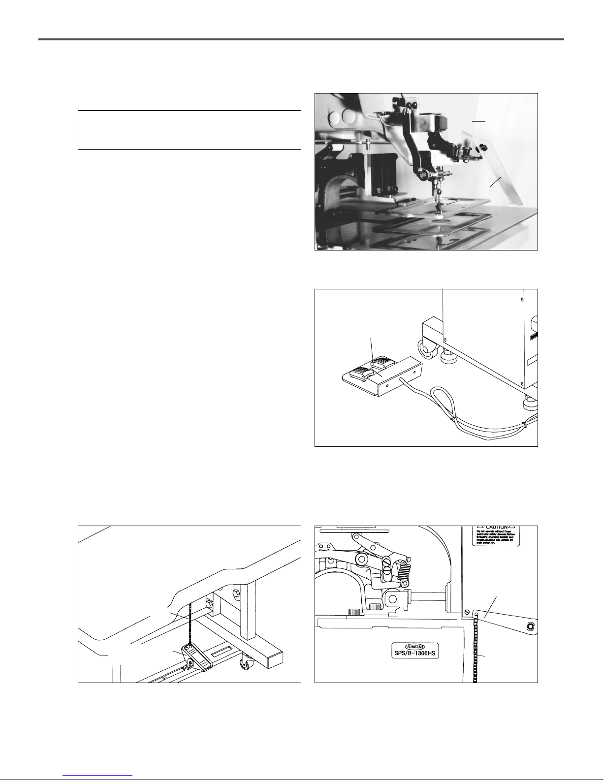
B. Install the safety plate on the side of the face plate.
[ Caution ]
For safety, have the plate on during operation.
C. Connect a plug of pedal switch with control box.
[ Fig. 14 ]
Safety Plate
Ass’y
Face Plate
[ Fig. 15 ]
Pedal Switch
D. Connect the chain between the manually operated pedal and the manual lowering lever.
If the distance between a manual pedal and linking chain is not fitted, unfasten the bolts and nuts of manual pedal
and adjust the manual pedal for proper distance.
[ Fig. 16 ]
Manually
operated Pedal
Linking Chain
Manual
Lowering Lever
Linking
Chain
19
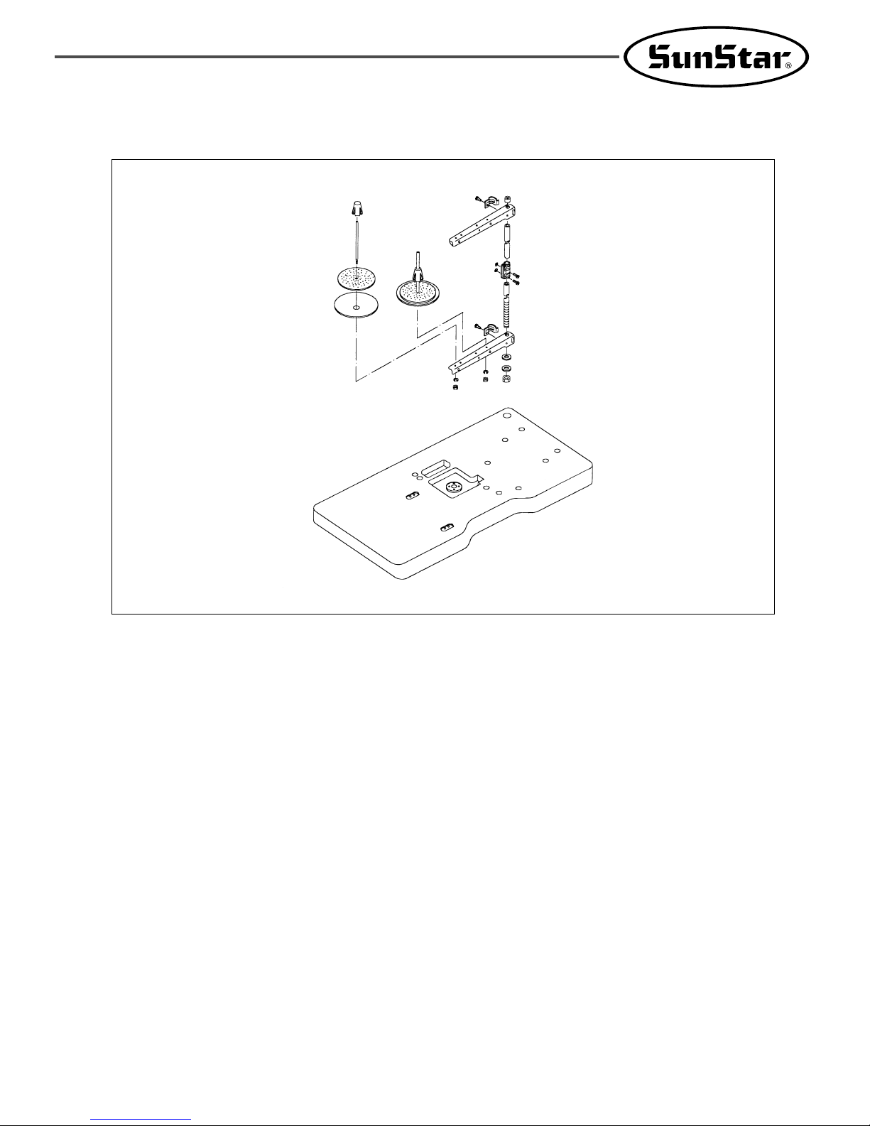
E. Install the Thread stand onto the table.
[ Fig. 17 ]
 Loading...