

Page 1

SuiiHtar
USSR'S
INVERTING
MRNURL
ClflMPD^VIC^S
SPS/R(B)-S€RI€S
Electronic
Pattern
Sewing
Machine
1)
2)
FOR
PLEASE
BEFORE
KE?
FOR
BREAKS
AT
MOST
CERTAINLY
STARTING
TH»
MANUAL
REF5)ENCE
DOWN.
USE
WHEN
WITH
READ
USE
IN
SAFE
EASINESS,
THIS
MANUAL
PLACE
THE
MACHINE
Page 2

1.
Thank
experience
will
functions,
more
2.
Please
sure
3.
The
product
4.
This
machine.
you
manufacture
sophisticated
read
to
properly
specifications
product
for
purchasing
accumulated
industrial
high
performance,
design
this
user's
use
performance,
Is
designed,
It
should
manual
the
of
the
without
not
be
our
product.
in
industrial
sewing
powerful
to
meet a number
machine
machine
prior
manufactured,
used
for
sewing
machines,
thoroughly
to
enjoy
are
subject
notice.
other
Based
operation,
its
and
than
on
the
machine
which
enhanced
of
user's
before
using
full
performance.
to
change,
sold
as
industrial
rich
expertise
production,
deliver
needs.
the
aimed
an
industrial
purpose.
SUNSTAR
more
durability,
machine.
to
enhance
and
diverse
and
Make
sewing
SUNSTAR
CO.,
LTD.
Page 3
COMTEMTS
1.
Notice
Before
2.
Inverting
1.
Installing
2.
Adjusting
3.
Installation
4.
Adjusting
5.
Removing
3.
Inverting
1.
Installing
2.
Adjusting
3.
Adjusting
4.
Adjusting
5.
Adjusting
6.
Adjusting
7.
Removing
Clamp
Clamp
Using
Devices
the
Inverting
the
Wiper
and
Adjustment
the
Reversal
the
Inverting
Devices
the
Inverting
the
Wiper
the
Inverting
the
Middle
the
Position
the
Label
the
Inverting
of
SPS/A-1306
Clamp
Devices
Parts
of
Pneumatic
Feeding
Clamp
Devices
of
SPS/A-1811
Clamp
Devices
Parts
Presser
Stop
Position
of
the
Inverting
Guide
Clamp
Devices
Frame
Plate
Feeding
of
Series
Control
Series
Frame
Reversal
Clamp
Feeding
Devices
Parts
Crank
Frame
-
-
4
5
5
6
7
8
9
10
10
10
10
12
12
13
13
4.
SPS/B-1507
1,
Specifications
2.
Structure
2,
Installation
5.
The
Use
of
1.
2.
6.
Parts
A.
B.
C.
D.
E.
F.
G.
H.
I.
Pattem
Adding
Programming
the
Book
Inverting
Inverting
Wiper & Presser
Pneumatic
Pneumatic
Pneumatic
Inverting
Inverting
Pneumatic
Series
Inverting
of
unit
of
machine
Inverting
Codes
Clamp
Clamp
Control
Control
Control
Clamp
Clamp
Control
Functions
by
for
Reversal
Devices
Devices
Foot
Mechanism
Mechanism
Mechanism
Mechanism
Devices
Devices
Mechanism
Clamp
Using
Mechanism
Mechanism
Mechanism
Mechanism
Devices
the
Inverting
to
the
Pattems
(SPS/A-1306
(SPS/A-1811
(SPS/A-1306
(SPS/A-1306
(SPS/A-1811
(SPS/A-2516
(SPS/B-1507HJ)
(SPS/B-1507HJ)
Code
Already
Programmed
Series)
Series)
Pneumatic
Electronic
Series)
Machine
Machine
Series)
Seires)
Series)
14
14
15
16
18
18
21
23
25
26
28
30
32
34
36
38
42
Attachments
1.
Pneumatic
2.
Pneumatic
3.
Pneumatic
circuit
diagram
circuit
diagram
circuit
diagram
for
SPS/A-1306
for
SPS/A-1811
for
SPS/B-1507
series
tumover
series
tumover
series
tumover
device
device
device
42
48
52
Page 4
1
Notice
1)
Before
2)
Before
3)
Using
you
range.
inputting
A
reading
A
presser
should
If
that a needle
If
ascend
be
Before
air
pressure
the
up-feed
patterns,
you
foot
careful
use
read
during
is
not
since
plate
is
put
check
patterns,
sewing
available
the
Using
by
air
pressure
and
reversal
over
the
reversal
the
pattern
incorretly a needle
or
after
finishing
for
sewing
range
control
feeding
feeding
number
sewing.
normal
inverting
around
devices,
frame
ascend
frame,
once
can
reversal
check
simultaneously
the
needle
more.
be
broken
working.
In
crank
if a needle
can
when
case
differs
be
of
from
is
with
broken
the
reversal
using
not
air
pressure
the
the
normal
attached.
Input
feeding
presser
frame
foot,
sewing
so
Page 5
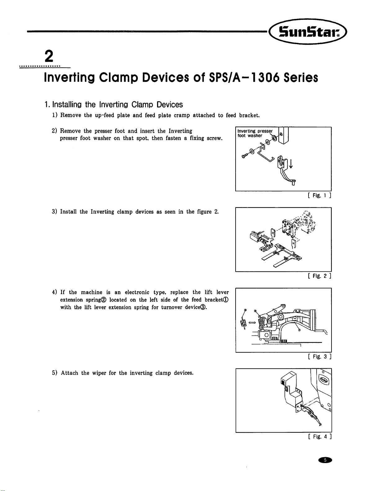
Inverting
1.
Installing
1)
Remove
Clamp
the
Inverting
the
up-feed
Clamp
plate
and
Devices
of
Devices
feed
plate
cramp
attached
SPS/A-1306
to
feed
bracket.
Series
2)
Remove
presser
3)
Install
4)
If
the
extension
with
the
the
presser
foot
washer
the
Inverting
machine
spring®
lift
lever
foot
and
on
that
clamp
is
an
electronic
located
extension
on
spring
insert
the
spot,
then
devices
the
as
type,
left
side
for
Inverting
fasten a fixing
seen
in
the
figure
replace
of
turnover
the
the
feed
device®.
screw.
2.
lift
lever
bracket®
Inverting
foot
washer
presser
[
[
Fig.
1
Fig.
2
5)
Attach
the
wiper
for
the
inverting
clamp
devices.
[
Fig. 3 .
Fig. 4 ]
Page 6
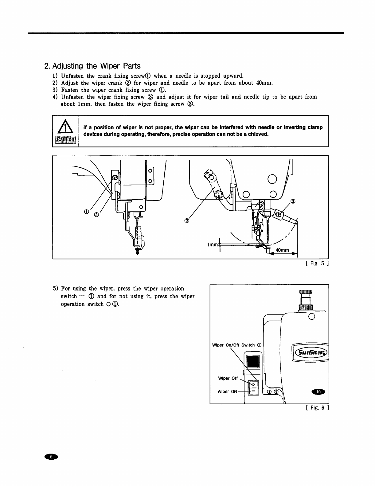
2.
Adjusting
1)
Unfasten
2)
Adjust
3)
Fasten
4)
Unfasten
about
the
the
the
the
the
1mm,
Wiper
crank
wiper
crank
wiper
crank
wiper
then
fasten
Parts
fixing
screw®
(D
for
fixing
fixing
screw
the
when a needle
wiper
and
screw
®.
(D
and
adjust
wiper fixing
screw
is
needle
to
it
for
d).
stopped
be
apart
wiper
tail
upward.
from
about
and
needle
40mm.
tip
to
be
apart
from
5)
For
using
switch — ®
operation
If a position
devices
the
and
switch
of
during
wiper,
press
for
O®.
wiper
is
not
operating,
not
therefore,
the
wiper
using
it,
proper,
the
precise
operation
press
the
wiper
operation
wiper
can
be
interfered
can
not
with
needle
be a chieved.
or
inverting
40mm
clamp
[
Fig. 5 ]
wiper
Wiper
Wiper
On/Off
Off
ON-
Switch
S
®
[
Fig.
6
Page 7

3.
Installation
A
A.
For
1)
2)
3)
4)
5)
Make
safety
pneumatic
Attach
Remove
figure
Connect
Open
Pull
the
turned
pressure
6)
Pull
the
the ( + ) direction,
decreases.
and
Adjustment
sure
that
the
power
accidents.
type
the
pressure
the
plug®
below.
the
air
the
finger
pressure
in
the ( + ) direction,
decreases.
pressure
Set
adjusterQ
attached
hoses®,®
valve®
adjuster®
Set
adjuster®
the
the
air
pressure
the
pressure
Hand
to
and
handle
air
handle
e
of
Pneumatic
is
turned
off
during
to
the
rear
to
T(D,
and
the
corresponding
pass
the
air
for
the
the
pressure
pressure
for
at
upper
increases.
at
the
appropriate
Control
parts
instaiiation
side
of
the
table
insert
it
into
solenoid
to
move
in.
reverse
increases.
the
When
device
When
appropriate
feed
in
the
it
is
turned
level
Solenoid
Reverse
(0.5~0.55MPa)
Valve
Device
Parts
and
leg
using
T®.
Connect
entrances.
in
the
arrow
it
is
turned
level
of
0.5~0.55MPa
arrow
direction.
in
the
of
0.4-0.45MPa
for
adjustment
the
the
in
order
screw.
air
hose®
direction.
in
the
(-)
When
(-)
direction,
(4~4.5Kfg/crf).
Solenoid
Reverse
(0.4~0.45MPa)
to
prevent
as
in
the
When
it
is
direction,
the
(5~5.5Kgf/cril).
it
is
turned
the
pressure
Valve
Device
in
for
Handle
[
Fig. 7 ]
Page 8
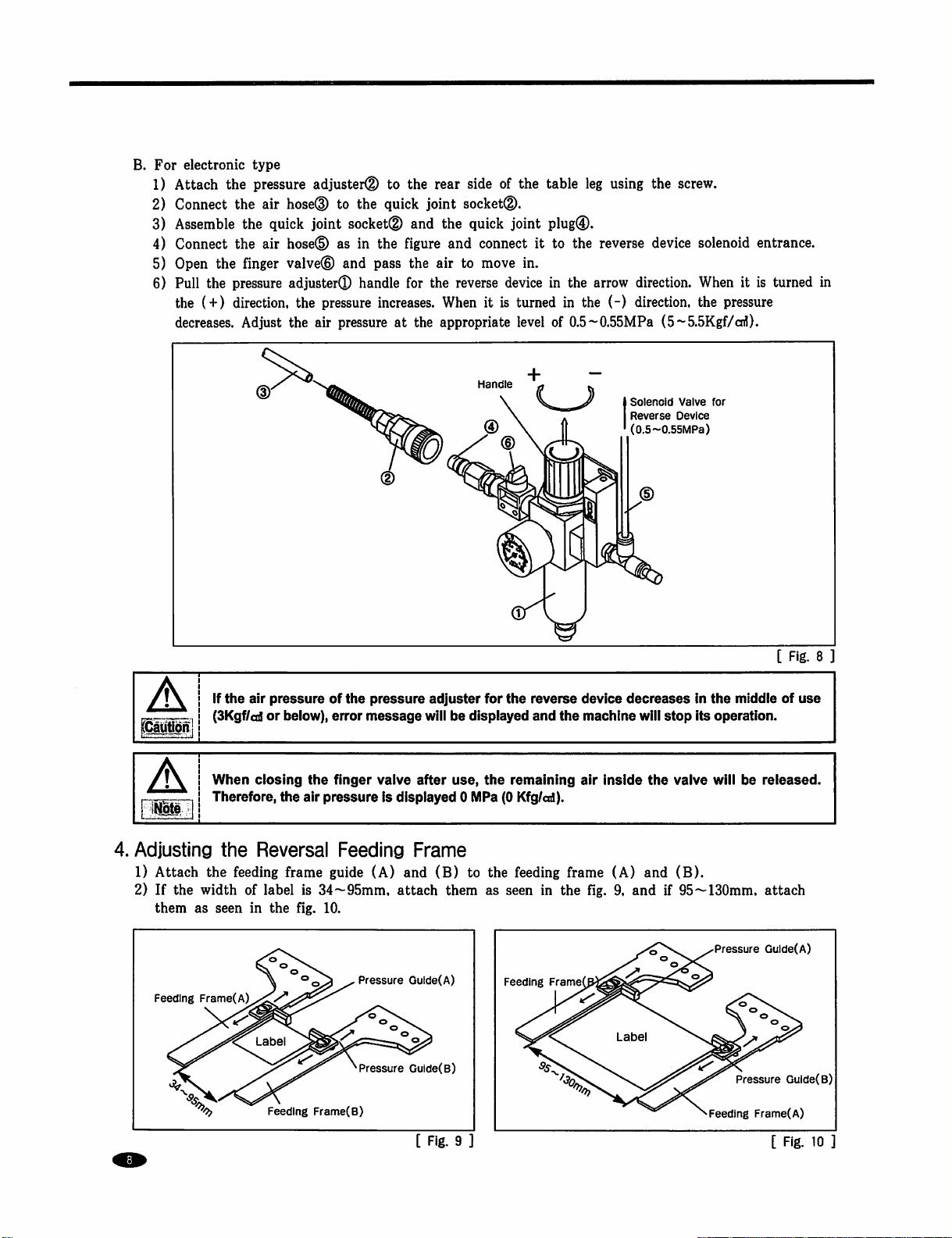
B.
For
electronic
1)
Attach
2)
Connect
3)
Assemble
4)
Connect
5)
Open
6)
Pull
the
decreases.
type
the
the
the
the
the
finger
the
pressure
(+)
direction,
Adjust
pressure
air
air
adjuster(D
hosed)
quick
joint
hosed)
valve®
adjuster®
the
pressure
the
air
to
the
to
the
quick
socket®
as
in
the
figure
and
pass
handle
for
increases.
pressure
at
rear
side
joint
socketd).
and
the
quick
and
connect
the
air
to
the
reverse
When
the
appropriate
Handle
of
joint
move
device
it
is
turned
the
table
plug®.
it
to
in.
in
level
of
leg
using
the
the
reverse
the
arrow
in
the
(-)
0.5~0.55MPa
device
direction.
direction,
(5~5.5Kgf/cnl).
Solenoid
Reverse
(0.5~0.55MPa)
screw.
solenoid
When
the
pressure
Valve
for
Device
entrance.
it
is
turned
in
aunon
A
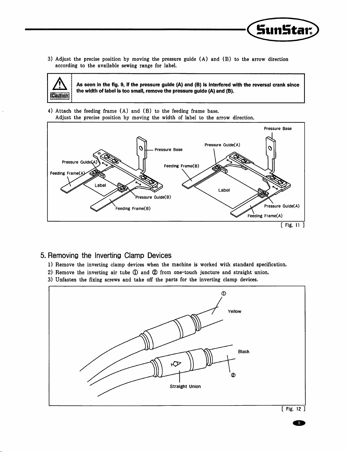
4.
Adjusting
1)
Attach
2)
If
the
them
Feeding
•KN,.
If
the
air
(3Kgf/cd
When
ciosing
Therefore,
the
the
feeding
width
of
as
seen
in
Frame(A)
^
pressure
or
the
of
below),
error
the
finger
air
pressure
Reversal
frame
guide
label
is
34~95mm,
the fig.
10.
^
Label
Feeding
Frame(B)
the
pressure
message
valve
is
Feeding
(A)
adjuster
will
after
displayed 0 MPa
Frame
and
(B)
attach
^Pressure
^Pressure
Gulde(A)
Gulde(B)
for
be
displayed
use,
the
to
the
them
as
the
reverse
and
remaining
(0
Kfg/cd).
feeding
seen
in
Feeding
Frame
device
the
machine
air
Inside
frame
(A)
the fig.
decreases
will
stop
the
and
9,
and
if
Labe
In
the
middle
Its
operation.
valve
will
be
(B).
95~130mm,
Pressure
Pressure
Feeding
[
Fig.
of
use
released.
attach
Gulde(A)
Guide(B)
Frame(A)
8
[
Fig.
9
[
Fig.
10
Page 9
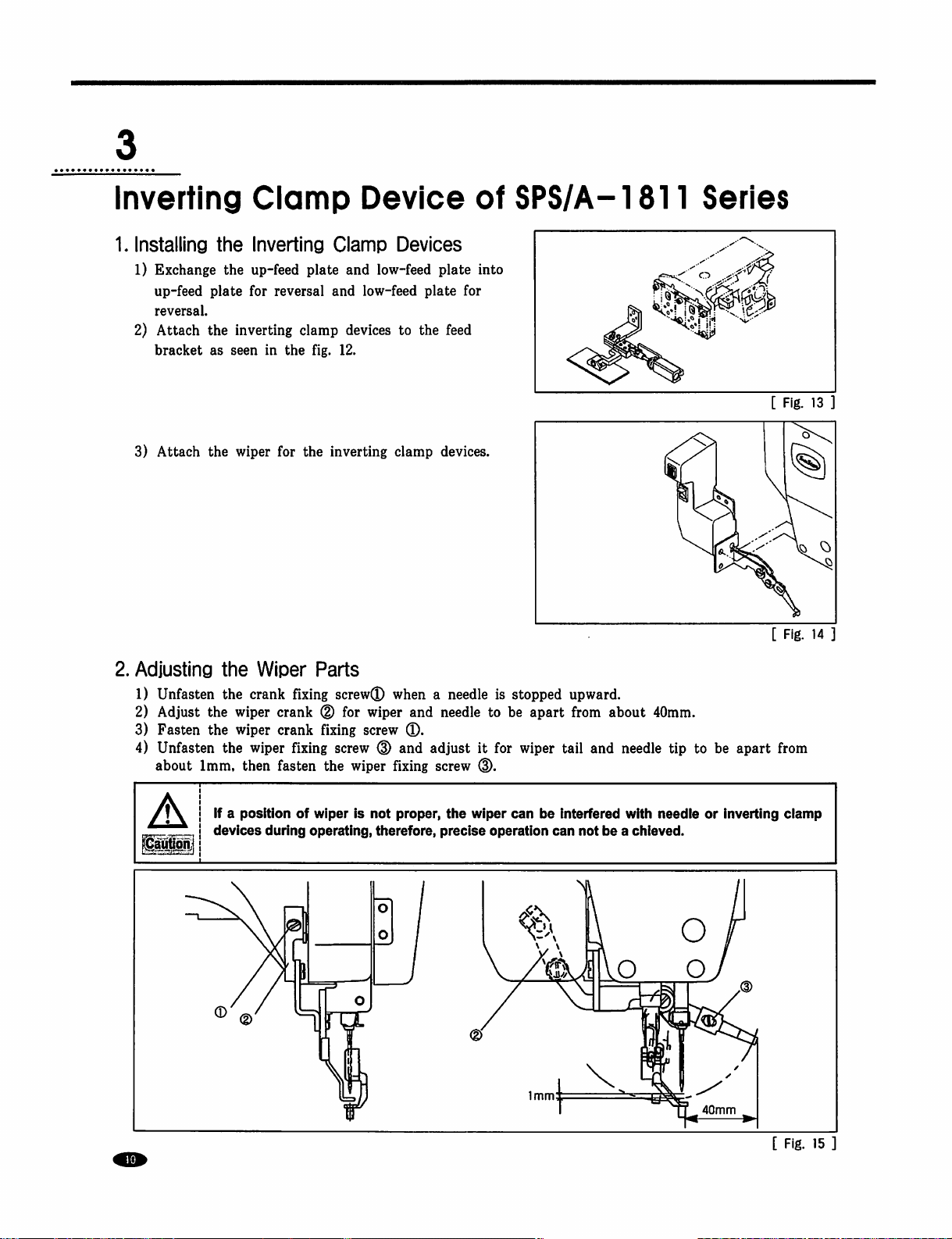
3)
Adjust
according
the
precise
to
position
the
available
by
moving
sewing
the
range
pressure
for
label.
guide
(A)
and
(B)
to
the
arrow
direction
f\ I As
A
4)
Attach
Adjust
Pressure
Feeding
I the
the
the
GuideCA)^
Frame(
seen
in
the
width
of
label
feeding
precise
frame
position
fig.
9,
if
is
too
(A)
by
Feeding
the
pressure
small,
remove
and
(B)
to
moving
Frame(B)
the
Pressure
Pressure
Gulde(B)
guide
(A)
and
the
pressure
the
feeding
width
of
Base
Feeding
Frame(B)
(B)
guide
frame
label
is
interfered
(A)
base.
to
the
Pressure
and
(8).
arrow
Guide(A)
Labe
with
direction.
the
reversal
Pressure
Pressure
Feeding
Frame(A)
crank
since
Base
Gulde(A)
[
Fig.
11
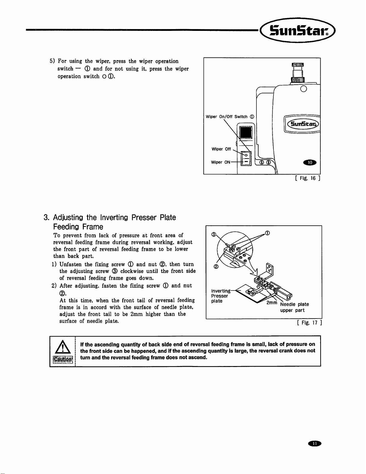
5.
Removing
1)
Remove
2)
Remove
3)
Unfasten
the
Inverting
the
inverting
the
inverting
the fixing
clamp
air
tube
screws
and
—
Clamp
devices
(D
and
take
Devices
when
the
(D
from
off
the
parts
machine
is
one-touch
for
the
straight
Union
worked
juncture
inverting
with
and
clamp
/
standard
straight
devices.
Yellow
Black
specification.
union.
[
Fig.
12
Page 10
Inverting
1.
Installing
1)
Exchange
up-feed
reversal.
2)
Attach
bracket
3)
Attach
Clamp
the
Inverting
the
up-feed
plate
for
the
inverting
as
seen
the
wiper
reversal
in
for
plate
clamp
the
fig.
the
Device
Clamp
and
and
devices
12.
inverting
Devices
low-feed
low-feed
to
clamp
plate
plate
the
feed
devices.
of
into
for
SPS/A-1811
Series
[
Fig.
[
Fig.
13
14
2.
Adjusting
1)
Unfasten
2)
Adjust
3)
Fasten
4)
Unfasten
about
A
the
Wiper
the
crank fixing
the
wiper
the
wiper
the
wiper
1mm,
then
If a position
devices
during
Parts
screw®
crank ® for
crank
fixing
screw
fixing
screw
fasten
the
wiper
of
wiper
is
operating,
when a needle
wiper
and
needle
®.
(D
and
adjust
fixing
screw
not
proper,
therefore,
the wiper
precise
is
stopped
to
be
it
for
wiper
(D.
can
operation
upward.
apart
from
tail
be
interfered
can
about
and
needle
with
not
be a chieved.
40mm.
tip
needie
to
be
apart
or
inverting
40mm
from
ciamp
[
Fig.
15
Page 11
5)
For
switch — ®
operation
3.
Adjusting
Feeding
To
prevent
reversal
the
front
than
back
1)
Unfasten
the
of
reversal
2)
After
(D.
At
this
frame
adjust
surface
using
the
wiper,
and
switch O ®.
the
Frame
from
lack
feeding
adjusting
adjusting,
is
part
part.
the
feeding
time,
in
the
front
of
needle
frame
of
fixing
screw
when
accord
press
the
for
not
using
Inverting
of
during
reversal
Presser
pressure
reversal
feeding
screw ® and
(D
clockwise
frame
goes
fasten
the
with
tail
to
plate.
the
fixing
front
the
be
2mm
surface
wiper
operation
it,
press
Plate
at
front
working,
frame
down.
tail
to
nut
(D.
until
the
screw ® and
of
reversal
of
needle
higher
the
area
be
lower
then
front
than
wiper
of
adjust
turn
side
nut
feeding
plate,
the
Wiper
On/Off
Wiper
Wiper
ON-
(D
^<2^
Inverting—
Presser
plate
Off
Switch
■
c;
©
C[5un5t^)
(D
(D
[
Fig.
16
]
Needle
plate
upper
part
[
Fig.
17
If
the
aunon
ascending
the
front
turn
and
side
the
quantity
can
be
happened,
reversal
feeding
of
back
and
frame
side
end
If
the
does
of
reversal
ascending
not
ascend.
feeding
quantity
frame
is
is
smali,
large,
the
lack
of
reversal
crank
pressure
does
on
not
Page 12
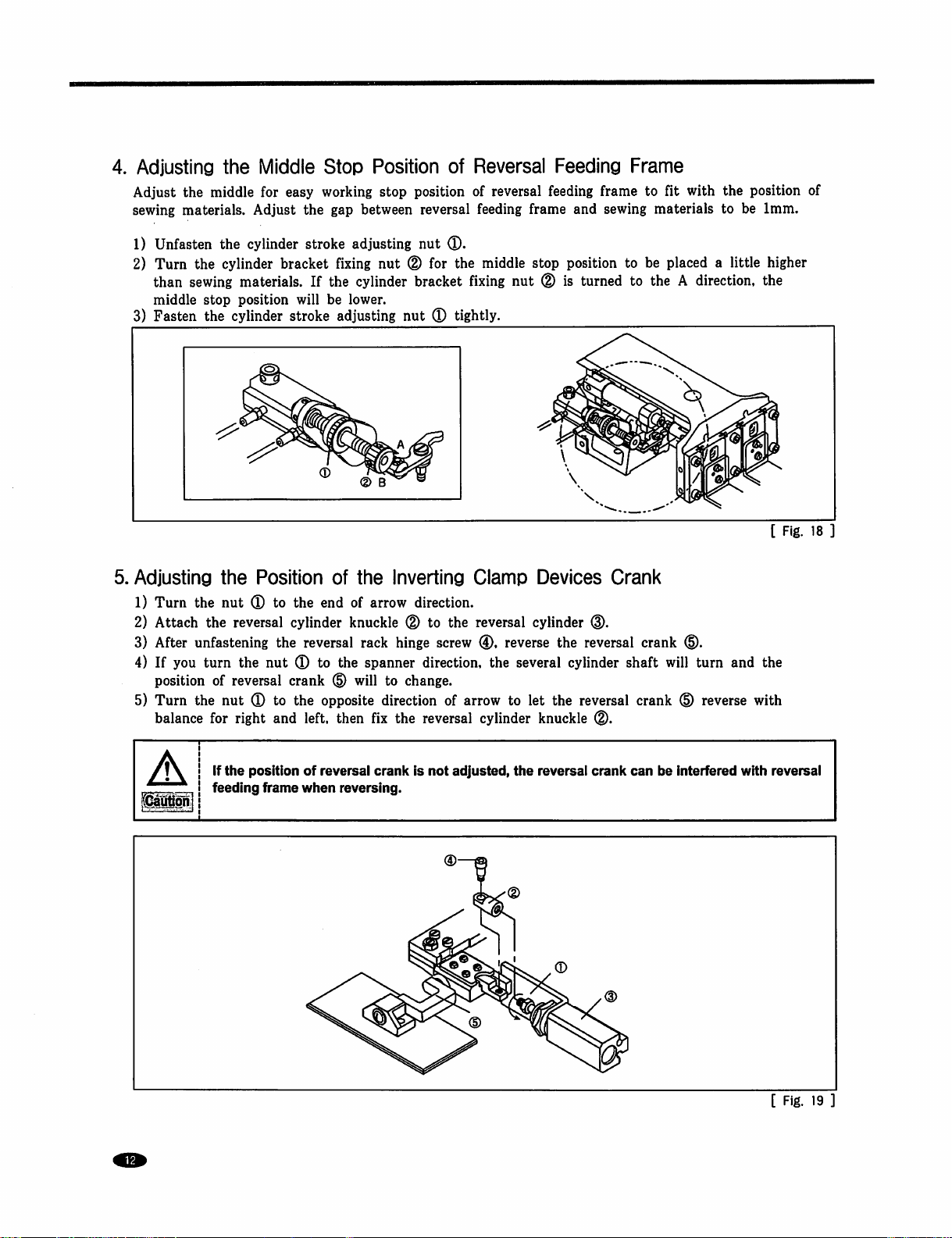
4.
Adjusting
Adjust
sewing
1)
2)
the
materials.
Unfasten
Turn
than
middle
3)
Fasten
5.
Adjusting
1)
Turn
2)
Attach
3)
After
4)
If
you
position
5)
Turn
balance
the
Middle
middle
the
sewing
stop
the
the
the
unfastening
turn
of
the
for
for
Adjust
the
cylinder
cylinder
bracket
materials.
position
cylinder
the
Position
nut ® to
reversal
the
the
nut ® to
reversal
nut ® to
right
and
Stop
easy
working
the
gap
stroke
will
stroke
the
cylinder
reversal
crank
the
left,
adjusting
fixing
If
the
be
lower.
adjusting
of
end
of
knuckle
the
d)
opposite
then
Position
stop
position
between
cylinder
the
arrow
rack
spanner
will
fix
reversal
nut
nut
(D
for
bracket
nut
(D
Inverting
direction.
(D
to
hinge
direction,
to
change.
direction
the
reversal
of
Reversal
of
feeding
®.
the
middle
fixing
tightly.
Clamp
the
reversal
screw
(D,
of
arrow
cylinder
Feeding
reversal
the
feeding
frame
stop
nut ® is
Devices
cylinder
reverse
several
to
let
the
knuckle
frame
and
sewing
position
turned
Crank
the
reversal
cylinder
reversal
(D.
Frame
to
fit
with
the
materials
to
be
placed a little
to
the A direction,
crank
shaft
will
crank
d).
turn
d)
reverse
to
and
position
be
1mm.
higher
the
[
Fig.
the
with
of
18
If
the
position
feeding
frame
of
reversal
when
reversing.
crank
is
not
adjusted,
the
reversal
crank
can
be
interfered
with
reversal
[
Fig.
19
]
Page 13
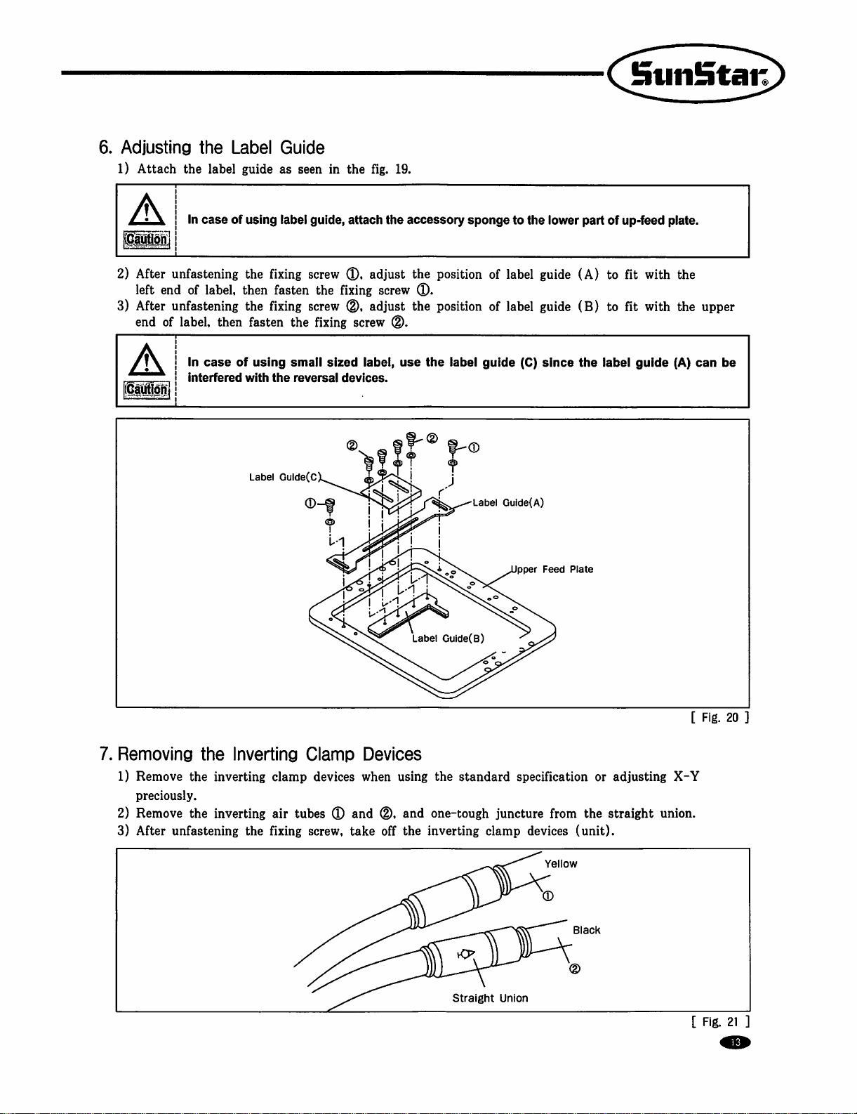
6.
Adjusting
1)
Attach
A
ICaliW]
2)
After
left
3)
After
end
A
the
Label
the
label
guide
In
case
of
unfastening
end
of
label,
then
unfastening
of
label,
then
In
case
of
interfered
Guide
as
using
label
the
fixing
fasten
the
fixing
fasten
using
with
the
Label
Gulde(C
seen
guide,
screw
the
screw
the
fixing
small
sized
reversal
in
the
attach
(D.
fixing
0,
screw
label,
devices.
fig.
19.
the
accessory
adjust
the
screw
0.
adjust
the
0.
use
sponge
position
position
the
label
guide
to
of
label
of
label
the
(C)
lower
guide
(A)
guide
(B)
since
the
C^^nSta^
part
of
up-feed
to
fit
to fit
iabel
plate.
with
with
guide
the
the
(A)
upper
can
be
7.
Removing
1)
Remove
preciously.
2)
Remove
3)
After
the
Inverting
the
inverting
the
inverting
unfastening
the
Clamp
clamp
air
fixing
devices
tubes ® and
screw,
Devices
when
(D,
take
off
Label
Guide(B)
using
the
and
one-tough
the
inverting
Label
Guide(A)
pper
standard
specification
juncture
clamp
Feed
Plate
from
the
devices
Ye
ow
(unit).
or
adjusting
straight
[
X-Y
union.
Fig.
20
Straight
Union
B
ack
[
Fig.
21
Page 14
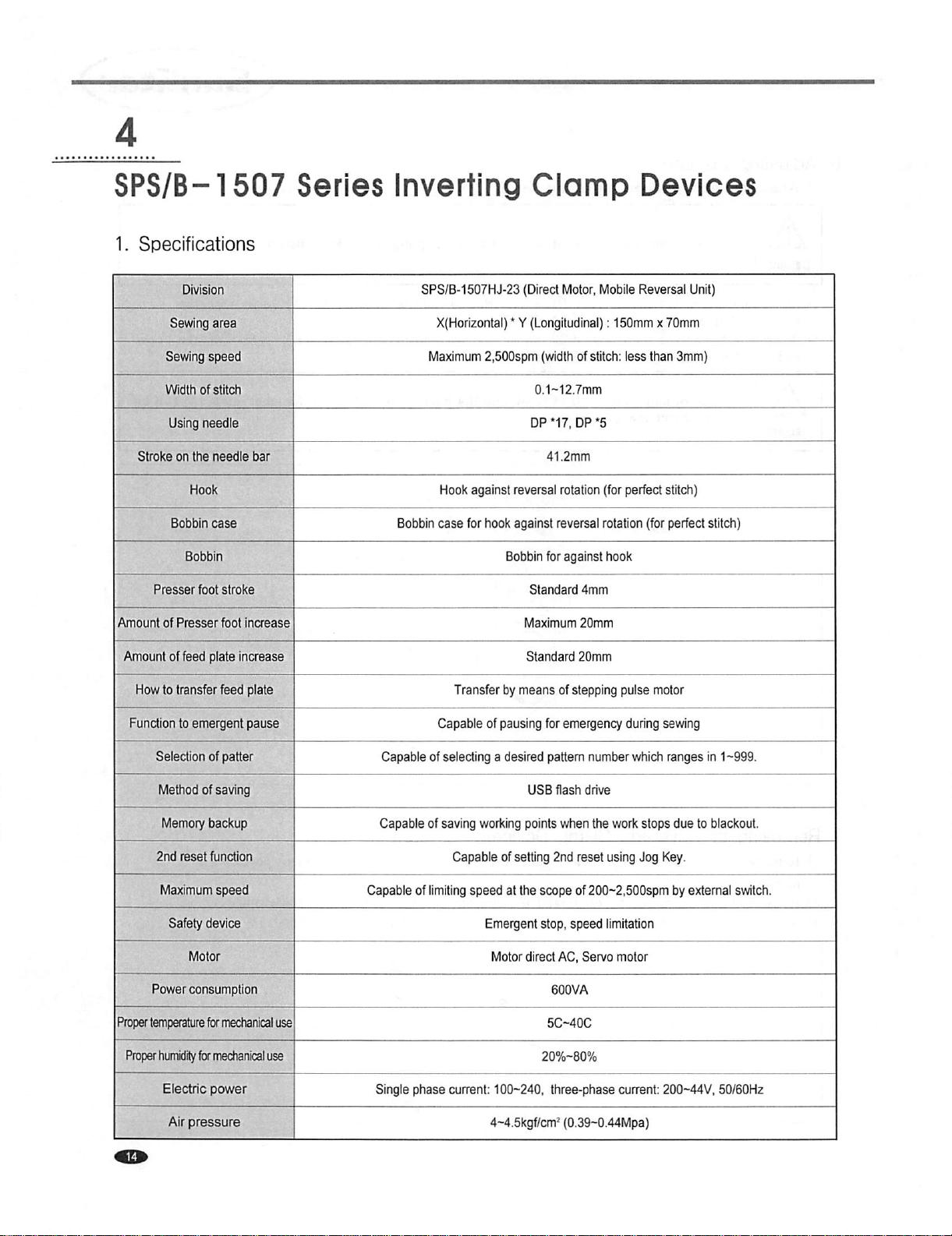
SPS/B-1507
1.
Specifications
Series
Inverting
Clamp
Devices
Sewing
Stroke
Presser
Amount
of
Amount
How
to
Function
Sewing
area
speed
Width
of
stitch
Using
needle
on
the
needle
Bobbin
case
foot
Presser
of
feed
plate
transfer
to
emergent
stroke
foot
increase
increase
feed
piate
pause
bar
SPS/B-1507HJ-23
X(Horizontal) * Y
Maximum
Bobbin
Hook
case
2,500spm
against
for
hook
Transfer
Capable
of
(Direct
Motor,
(Longitudinal):
(width
of
DP
*17,
DP
reversal
rotation
against
reversal
Bobbin
for
against
Standard
Maximum
Standard
by
means
pausing
4mm
20mm
20mm
of
stepping
for
emergency
Mobile
Reversal
150mm x 70mm
stitch:
less
*5
(for
perfect
rotation
hook
puise
during
than
stitch)
(for
perfect
motor
sewing
Unit)
3mm)
stitch)
Selection
Method
Memory
2nd
Maximum
Safety
Power
Proper
temperature
Proper
humidity
Electric
of
patter
of
saving
backup
reset
function
speed
device
consumption
for
mechanical
for
mechanicai
power
use
use
Capable
Capable
Capable
of
Single
phase
of
selecting a desired
of
saving
working
Capable
limiting
of
speed
setting
at
the
Emergent
Motor
current:
100-240,
4-4.5kgf/cm^
pattern
number
USB
flash
drive
points
when
2nd
reset
scope
of
200-2,500spm
stop,
speed
direct
AC,
Servo
5C-40C
20%-80%
three-phase
(0.39-0.44Mpa)
which
the
work
stops
using
Jog
limitation
motor
current:
ranges
in 1 ~999.
due
to
blackout.
Key.
by
external
200-44V,
50/60H2
switch.
Page 15
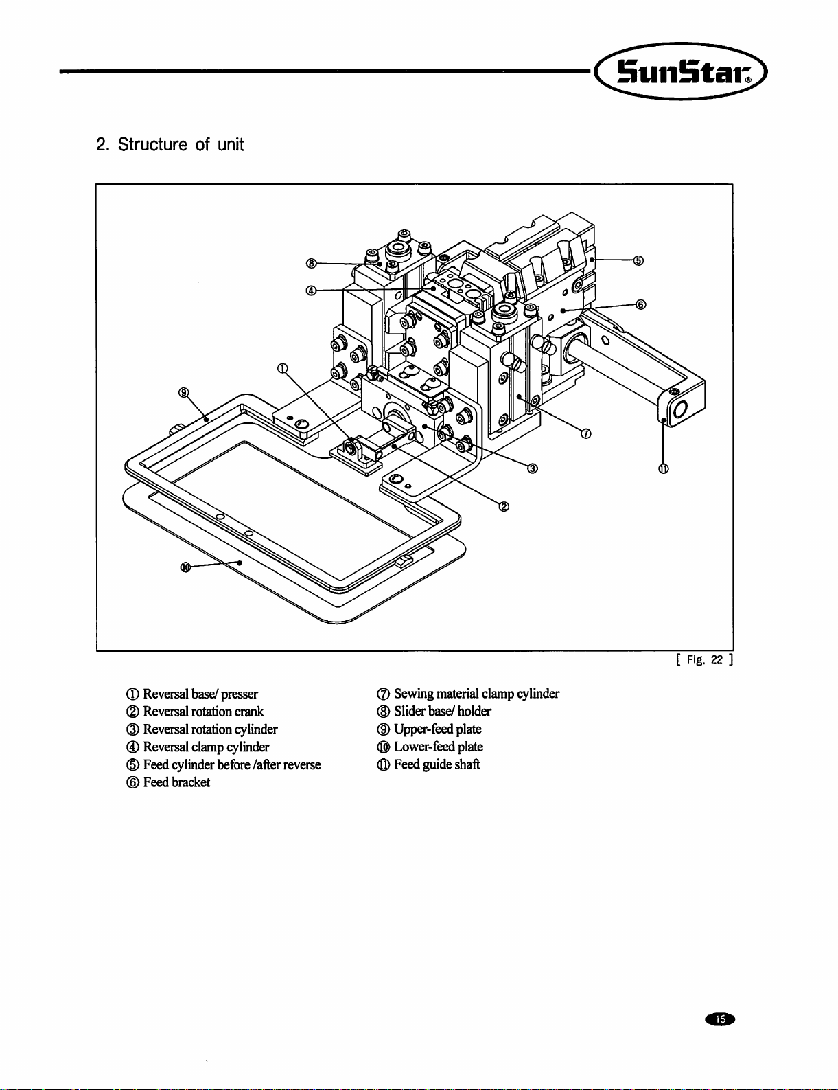
2.
Structure
of
unit
®
Reversal
(D
Reversal
(D
Reversal
®
Reversal
(D
Feed
(©
Feed
base/
presser
rotation
rotation
clamp
cylinder
bracket
before
crank
cylinder
Under
/after
reverse
®
Sewing
(H)
Slider
base/
(D
Upper-feed
®
Lower-feed
(Q)
Feed
guide
material
clamp
holder
plate
plate
shaft
cylinder
[
Fig.
22
Page 16
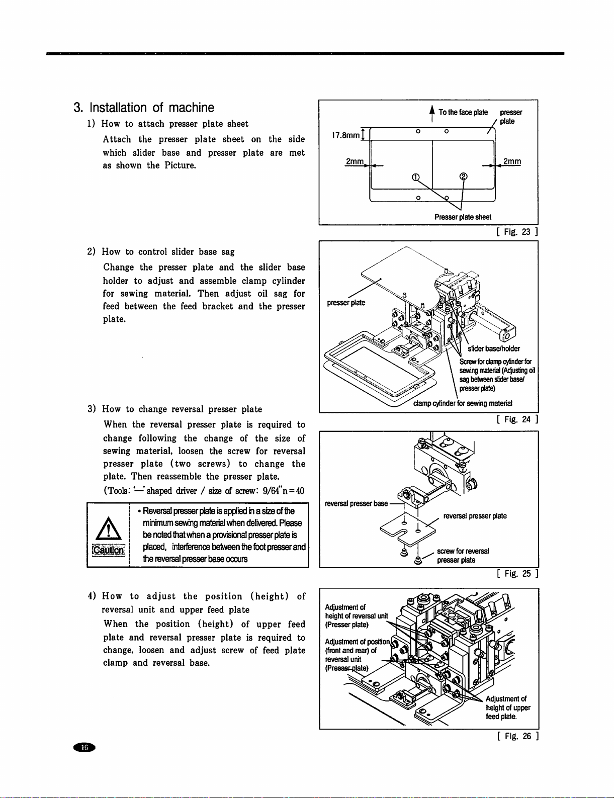
3.
Installation
1)
How
to
Attach
which
as
shown
2)
How
to
Change
holder
for
sewing
feed
between
plate.
of
attach
the
presser
slider
base
the
Picture.
control
the
presser
to
adjust
material.
the
machine
presser
slider
plate
and
plate
and
feed
plate
base
assemble
Then
bracket
sheet
sheet
presser
sag
and
the
adjust
and
on
plate
slider
clamp
oil
the
the
side
are
met
base
cylinder
sag
for
presser
17.8mm|_
2mm^
presser
plate
o
A
To
the
'
o
Presser
face
plate
plate
sheet
slider
Screw
for
presser
/ plate
2mm
[
Fig.
base/holder
damp
cylinder
23
for
3)
How
to
change
When
the
reversal
change
sewing
presser
plate.
following
material,
plate
Then
(Tools: — shaped
Reversal
minimum
be
placed,
the
4)
How
to
adjust
reversal
When
plate
change,
clamp
unit
the
and
loosen
and
reversal
reversal
presser
the
loosen
(two
screws)
reassemble
driver / size
presser
plate
sevwng
material
noted
that
when a provisional
'(nterference
reversal
presser
the
and
upper
position
reversal
presser
and
(height)
adjust
base.
presser
change
the
plate
plate
of
screw
is
to
the
presser
of
screw:
Is
appl'ed
when
delivered.
presser
between
the
base
occurs
position
feed
(height)
plate
of
plate
is
screw
required
the
size
for
reversal
change
plate.
9/64"n=40
in a size
of
Rease
plate
toot
presser
upper
required
of
feed
to
of
the
the
is
and
of
feed
to
plate
reversal
presser
base
Adjustment
height
(Presser
Adjustment
(front
reversal
(Presse
of
of
reversal
plate)
of
and
rear)
unit
position^
of
unit
damp
cylinder
for
sewing
matenal
[
Fig.
24
—
J
1 ,
screw
presser
reversal
presser
for
reversal
plate
plate
[
Fig.
25
Adjustment
height
feed
plate.
[
Fig.
of
of
upper
26
Page 17

5)
How
Turn
table
accelerate
A.
Control
B.
Control
C.
Control
6)
How
®
Check
If
(E)
Stroke
stroked)
©
How
®
®
®
to
control
clockwise
as
shown
the
speed.
the
the
operating
the
in
rotation
speed
pressure
to
use
the
stroke
out
that
not.
set
the
switch
for
is
for
to
use
Lower
the
upper
When
the
sewing
plate
and
then
middle
When
stroke
upper
speed
knob(D
the
Adjust
feed
of
parameter
parameter
three
operating
of
below
the
speed
cylinder
reversal
switch
(Function
at
strokes
reversal
feed
plate
material
fix
sewing
or
right
stroke
feed
plate
goes
of
reversal
speed
controller®
picture
in
proper
of
reversal
after/before
unit's
presser
no:
'4'
(Refer
is
provided:
press
by
pressing
is
properly
material.
to
the
down
to
unit
order
to
speed
and
cylinder
reversal
60)
related
to'
Change
Right
plate,
and
right
stroke®
positioned,
(In
order
full
once
the
bottom,
of
Solenoid
lower
the
then
fix
unit
to
general
of
Parameter
stroke®
left
stroke®
press
to
change
again.
Then
press
valve
speed.
with
is
for
is
to
fix
middle
the
it
left
stroke®
attached
Turning
the
screw®.
sewing
the
goes
is
for
General
operating
for
starting
position
stroke®
position
up
to
to
to
the
lower
counterclockwise
set
at
'4'
Sewing'of
upper
manual)
feed
plate,
sewing.
of
sewing
to
lower
of
sewing
the
start
material.
reversal
material,
initial
position.
sewing.
[
Fig.
part
of
is
to
27
middle
presser
press
CD
®
(D
©
(D
(D
©
[
Fig.
28
Page 18

The
They
attention
interfered
inverting
other
1.
Use
are
used
to
with
devices),
is
to
program
Pattern
(D
Insert a USB
d)
Press a BBIB
d)
By
using
menu,
upper
of
Inverting
when
inverting
that
inverting
needle
one
bar.
is
to
newly.
Program
input
clamp
There
Programming
flash
drive
Keys
then
press
feed
plate
descends
clamp
are
call
the
Starting
the
inverting
by
into
.
and
devices
is
interfered
two
ways
already
Ponit
AV.
\
Jump
Code
Using
the
USB
move
to
key.
At
move
to
Functions
are
available.
with
needle
for
inputting
programmed
Sewing
.
\
as
the
Starting
PI
P6
Sewing
'1'
Inverting
terminal,
"2.
Program"
this
time,
the
origin.
During
bar.
inverting
pattern
Point
Finishing
Code
the
programming
or
inverting
codes
to
add
<<
B•
3.
4.
the
cylinder
(the
the
inverting
Main
Program
Bobbin
Machine
patterns,
drive
orders
to
codes
pay
part
drive
and
Menu>>
Wind
Test
is
the
®
After
pressing
pressing
If
you
date,
then
operated
|^BB
j^BH^eys.
press
BbbI
key.
upper
feed
data.
key.
move
Then
the
plate
to
the A point
press
machine
moves
according
key.
operates
pattern
the
by
ORIGIN
X:OOOOOA
Y:
0 0 0 0 OA
Function
004:JUMP
X : ? ? ? ? ?
Y . 9 9 9 9 9
N:
OOlB
JUMP
X:?????A
Y:?????A
Function
NiOOOOO
Code?B
NONE
N:000??
Code?B
Page 19

<3)
After
pressing
pressing
ktMBftW
09
key.
set
up
[0][0][l].
the
2nd
origin
by
<Function
Stiiiiatai'
Code>
(Z)
Press
After
point
010
d)
If
data,
operated
pressing
PI.
by
you
press
then
upper
data.
^^^0
pressing
^^0
key.
feed
key,
BHH
plate
move
the
machine
moves
to
the
sewing
Then
press
operates
according
start
09
pattern
the
CODE
SEC
X:?????A
Y:
?????A
No
-ORG
Function
004:JUMP
X : ? ? ? ? ?
Y : ? ? ? ? ?
N : 0 0 1 ■
JUMP
X:?????A
:
ilO
N:000??
Code?|
N:000??
1
NO]
NONE
®
After
using
(For
width,
<0)
Move
then
coordinates
®
If
you
data,
operated
pressing
^9
example,
to
press
then
|H0
keys,
input
[0][3][0].)
the
P2.
of
press
vaama
upper
data.
if
each
key.
then
press
you
want
PS.
and
key
corner.
key.
feed
plate
input
the
^O^Bl^O
to
set
P4
by
each
time
the
machine
moves
stitch
key.
up
3mm
using
to
input
operates
according
width
by
as
stitch
keys,
the
pattern
the
007;LINE
WIDTH:l3
007;LINE
X : ? ? ? ? ?
Y : ?
? ? ? ?
N;
003
LINE
X:?????A
0
[0.Imm]
N:00???
NONE
Page 20

After
pressing
pressing
HIB
keys
[0][4]and
input
the
[9].
inverting
code
by
<Function
Code>
(g)
Press
pressing
(©
After
Program
S
confirming,
key.
P5
j
key.
key.
and
1.
input
P6
Operate
by
the
the
inverting
using
inverting
code
cylinder
by
by
pressing
CODE
049:REV
PCS
REV
X:?????A
Y:?????A
No
:
SET
Function
007:LINE
X : ?
? ? ?
Y • 9 9
A ♦ • • • • •
N:
0021
:
SET
CO/1]
NONE
N:00???
Code?!
?
9
©
Press
"000 I TRIM"
screen
using
If
data,
operated
After
you
on
pressing
press
then
key
the
keys.
upper
data.
to
input
appears
right
appears
key.
Then,
key.
feed
trimming
on
the
again.
move
press
the
machine
plate
moves
code.
screen,
then
to
the B point
operates
according
key.
the
pattern
the
by
TRIM
X:?????A
Y:?????A
Function
004:JUMP
X : ? ? ? ? ?
Y : ? ? ? ? ?
N:OOll
JUMP
X:?????A
NONE
N:00???
Code?|
NONE
N:00???
Page 21

BuiiHtai'
2.
Adding
1)
Perform
After
want
a
(For
input
For
key.
ascends.
test
pressing
to
save
USB
flash
example,
[5][5]and
completing
The
To
the
Reading
codes.
0
(D
d)
the
Insert a USB
added
Press
After
key.
upper
sewing.
KBytlii«a
by
using
key.
Save
drive
as
to
save
[l].)
pattern
upper
feed
back
to
Codes
pattern
flash
the
inverting
key.
moving
feed
to
praco
plate
key,
input
the
keys,
and
the
generated
the
relevant
the
pattern
data
plate
moves
the
initial
for
Reversal
that
does
drive
code.
"2^Progr^"
descends
number.
number
generation,
to
the
screen,
not
have
that
has a pattern
menu
L-ay
At
and
moves
number
press
pattern
as
press
origin,
press
to
the
data
inverting
by
using
this
time,
to
the
you
into
551,
_____
then
key.
Patterns
to
be
the
origin.
015
NO:
<<Main
E•Program
3.Bobbin
4.Machine
Already
Programmed
<<<Main
B.P
3.Bobbin
4.Machine
ORIGIN
iPTRN
151
rogram
WRITE
Menu>>
Wind
Test
Menu>>
Wind
Test
(D
After
pressing
number
change
to
(For
2)
Inserting
(D
Add
keys,
the
After
by
by
read
example,
[5][0][0].)
the
the
and
inverting
pressing
pressing
key,
that
contains a sewing
using
the
pattern.
to
inverting
inverting
move
code.
B
read
code
code
to
the
keys.
keys,
key.
input
speed
then
pattern
P4
[0][4]
by
number
using
that
input
and
the
pattern
you
press
MWIfcililri
500.
you
want
the
inverting
[9].
want
input
to
add
to
key
code
X:GOOOGA
Y:GGGGOA
Function
G14:PTRN
LINE
X:?????A
Y:?????A
Function
<Function
N:OOGOO
Code?E
READ
N:000??
Code?|
Code>
CODE
No
Page 22

Q)
Press
Operate
™waa
the
key.
inverting
cylinder
by
pressing
049:REV
3)
(©
Test
®
After
confirming,
inverting
code.
press
sewing
Press
upper
and
ascends
adjusting
once,
the
press
^SI^^B^^^Bswitch
sewing
sewing,
point
then
By
repressing
After
the
the
origin,
feed
proper
key,
upper
comes
the
upper
key.
plate
moves
to
turn
speed
if
you
feed
to
start.
up-feed
ascends.
BDD
feed
the
SBOBIRSS
After
moving
to
on
the
for
press
plate
After
plate
plate
key
to
to
the
the
sewing
test
sewing
descends,
once
completing
moves
complete
descends
and
more,
to
the
the
and
turns
off.
input
origin,
start
by
point
After
pressing
switch
if
you
the
test
the
test
sewing
test
sewing.
moves
the
the
start
to
POS
REV
X:?????A
y: ? ? ? ?
?A
Function
<Test
ORIGIN
XrOOOOOA
[0/1]
SET
N:00???
Code?|
Sewing>
SP : 12
N:00000
4)
Saving
(0)
©
iWi^BwwM
as
After
pressing
number
press
@!lS^Hikey.
data
into a USB
(For
example,
input
[5].[5]and
the
plate
moves
To
complete
feed
plate
press
£|gB|
new
pattern
you
want
to
the
key.
After
ascends.
key.
number
key,
to
save
Save
flash
drive
to
save
the
[2].)
During
flickers.
the
After
turns
origin.
pattern
moving
To
back
input
the
by
using
the
generated
as a relevant
pattern
number
saving
completing
off,
and
the
data
generation,
to
the
origin,
to
he
initial
pattern
key.
pattern
number.
as
the
pattern,
the
saving,
upper
feed
press
the
screen,
and
552,
upper
Y : 0 0 0 0
OA
Function
015:PTRN
NO
:i!52
ORIGIN
X:OOOOOA
y:OOOOOA
Function
<<Main
B.Program
3.Bobbin
4.Machine
Code?!
WRITE
N:00000
Code?l
Menu>>
Wind
Test
Page 23

Parts
book
WARNING
1.
soil
3114
4^'Hl
2.
-&
^4^
3.
4^
<^131
1.
The
parts
when
they
purchased
2.
This
is a parts
3.
Parts
are
Part
^0]
classified
are
as
Subject
71]
It]4
Book^^
44'^1
as
separtately
ass'y
items
book.
It
to
change
A)
4^1^
^
1
ass'y
items
assembled.
only.
cannot
be
used
in
Design
4^9^
^-£
may
4^
Sl^M4.
cause
Hence,
as a manual.
Without
^4^1
damage
when
Prior
to
they
Notice.
;^1|-|-
^^o]
7V-^tM4.
4^
•|-7]-tM4.
the
machine
are
ordered,
or
bad
they
can
^
^o]
sewing
be
Note
oI-eH
http:
//www.sunstarcs.com
7]-®]^
Slit
7l^£l
4i4-i-
4i44
You
can
make
an
http I //www.sunstarcs.com
You
can
request
In
parts
Management - Order
you
can
place
an
If
you
don't
know
In a download
This
parts
book
list,
is
it
4^4
i2lt
4444
order
for
parts
order
the
parts
you
can
classified
4o]i'Hl
4^
for
the
you
Management - Order
by
entering
number,
read
by
44-i
parts
want
after
the
click
parts
the
mechanism,
;a44>^]ol
s.at^
ti
of
Sunstar
login
part
the
book
-tl^t
4-S-4-b
44
machine
if
you
Registration
number
parts
book
by
searching
therefore
4^
ttt
4^
7)^4
?l:7]7i-
-§-<.1^44
to
connect
are a registered
and
quantity.
menu
model
you
bar.
can
Internet
entry,
you
use.
find
member.
part
address,
easily.
Page 24

R
Inverting
Clamp
Devices
Mechanism ( SPS/A-1306
Series
)
i
Page 25

Parts
No.
GP-036450-00
GP-048392-00
52A002S-306H
DSC-BJ0D4800
SW-0103-9011
52A005S-306H
SC-0524-4122
52A007S-306H
52A008S-306H
GP-036449-00
52A010S-306H
52A011S-306H
SC-0543-4525
22S021S-306H
52A014S-306H
52A015S-306H
SC-0502-4125
52A017S-306H
SC-0548-4122
PPP-CA005900
09A029S-811H
09A030S-811H
49A029S-811H
05A039S-8nH
01-017W-1600
GP-017759-02
09A021S-811H
09A023S-811H
52A022S-306H
Inverting
Base
Inverting
Crank
Inverting
Crank
Screw
{1/8"n=40)
Inverting
Crank
Screw
(0.33mm
Inverting
Inverting
Presser
Feeding
Feeding
Screw
Guide
Guide
Screw
Inverting
Screw
Inverting
Inverting
Inverting
Air
A"r
Inverting
Inverting
Plate
Frame
Frame
(0.46mm
Presser
Presser
(0.36mm
(0.13mm
Cylinder
Elbow
Hose
(M)
Lifting
Lever
Rack
Support
Cylinder
Cylinder
Rack
Presser
Presser
Base
n=44)
Base
Base
(A)
(B)
n=40)
(A)
(B)
n=40)
Bracket
n=28)
Ass'y
Knuckle
Hinge
Plate(A)
Plate(B)
Tension
Sprra
(CQ2B16-7.5D)
Screw
(Invert
Ctarm^
eta
Bfloi±
afs
3ga
eta
383
SUM(1/8"n=40)
"2W
m
383
mQ\±
eta
m
0!^
0!^
SUM
__
¥Se
mioi^:
iH[oi±
$BJI@J(A)
$BiSj(B)
7fOIE
(A)
7fOIE
(B)
"sum
m
SUAf
eia
m
ya ^ §!XIUM
OIIOI
0IICH2±
SIM
eia
m
SSeiBi
sBta
SJiia © (cq2bi6-7.5d)
ui
gjS¥
¥ie
(a)
¥ss
(b)
o|S
!ntiiiHtar
Notc)Part
A-28
marked
with a sign
if
is
exclusively
used
for
electronic
equipment.
Page 26

B
Inverting
Clamp
Devices
Mechanism ( SPS/A-1811
Series
)
Page 27

Ref.
B-1
B-8
B-9
B-10
B-11
No.
GP-048393-00
09-A017S-811H
09A026S-811H
09A021S-811H
09A011S-811H
09A010S-811H
SC-0183-4122
22A043S-811H
06-022W-2350
SC-0508-4515
SN-0120-4000
09A025S-811H
SC-0156-4118
SC-000458-00
09A013S-811H
09A015S-811H
09A016S-811H
09A018S-811H
09A019S-811H
SW-0120-1011
SC-0200-4123
09A020S-811H
09A021S-811H
09A022S-811H
SC-0120-4120
09A023S-811H
09A029S-811H
09A030S-811H
09A027S-811H
SC-0151-3118
09A028S-811H
49A003S-811H
05A039S-811H
09A-031S-811H
22A043S-811H
GP-013524-02
09A037S-811H
09A032S-811H
09A033S-811H
09A034S-811H
09A035S-811H
SC-0543-4525
01-017W-1600
Inverting
Inverting
Inverting
inverting
Inverting
Inverting
Screw
Screw
Washer
Screw
Nut
Inverting
Screw
Screw(B)
Washer
Invering
Invering
Washer
Screw
Inverting
Inverting
Inverting
Screw
Screw
Crank
Crank
Rack
Clamo
Clamp
Clamp
(0.61mm
For
(0.61mm
Rack
(0.36mm
For
Needle
Bearing(A)
Needle
Bearing(B)
Support
Support
(0.46mm
Presser
Presser
Presser
For
Inverting
For
Inverting
Cylinder
Inverting
Rack
Inverting
Cylinder
Screw
(0.61mm
Air
Cylinder
Air
Elbow
Air
Hose
(M)
Feed
Plate
Screw
Lower
Feed
Upper
Feed
Label
Guide
Label
Guide
Label
Guide
Seet
for
Label
Screw
(0.46mm
Washer
Shaft
Spacer
n=28)
Feed
Plate
n=28)
Cover
n=40)
Inverting
Base
Base
n=40)
Plate
Plate
Plate
Presser
Inverting
Presser
Knuckle
HIinge
Bracket
n=28)
Ass'
y
Clamp
(R)
Plate
Plate
(A)
(6)
(C)
Guide
(B)
n=40)
Base
Clamp
Clamp
"A"
"B"
"A"
"B"
"D"
Plate
Screw
B
"A.B"
Plate
"D"
yaasiE
e!|
SUAf
moiEa
m
asuM
am.
sia
as
iUM
m
ggs
UOIS
mm
UOIl
bilOig
m
^
m
iUAf
ya
¥S&"A"
ya
¥SS"B"
m
¥13
m
¥B®(A.B)
m
¥sa(D)
m
&E
Sij
iUAf
oilol
ma
oioi
OUCH
QIOIE
§UAf
81III0IE
^nioiE
Bfai
7I0IE
Biai
PfOlE
Biai
7fOIE
Bia
:'IOIE
SUAI
m
las
m
UM
(A)
(B)
8!I0I±"B-
"D"
lUM
u
SXILfM
(S
&
a
(A)
(B)
(C)
(B)
asm
(B)
[KT7108N]
[KT
71010]
SUAJ
A|e
fiiiiiHtai'
Page 28

c
Wiper & Presser
Foot
Mechanism
i
I
Page 29

Ref.
C-1
No.
Parts
No.
11S036S-306H
09A004S-811H
SC-0543-4525
09A005S-8
SC-0525-4122
09A001S-811H
09A006S-811H
SC-0330-4422
06-034W-7400
09A007S-811H
05A045S-811H
09A008S-811H
09A009S-811H
01-071W-1600
SC-0502-4125
09A002S-811H
09A036S-811H
06-040R-106L
Wiper
On/Off
Switch
Ass
y
Wiper
Cover
Screw
(0.46mm
Wiper
H
Base
Screw
(0,46mm
Wiper
Solenoid
Nut
{M4XP0.7)
Wiper
Crank
Screw
(0.61mm
Washer
Wiper
Connecting
Hinge
Screw
Wiper
installing
Wiper
Washer
Screw
(0.36mm
Emergency
Presser
Washer
Stud
for
Rubber
Foot
Wiper
for
Ass'
For
Plate
Switch
Stopper
\Woer
n=40)
n=40)
y
n=28)
Rod
B-11
n=28)
Stopper
etOIIH
Zfi
mm
lUAf
mm
§UAf
SIOIHI
ui
SfOlIB
33H
iuXi
m
suoiia
sa
SfOIQj
2foiia
m
m
^5^
m
SfOia
±£IB
2fOI3Il
±91*1®
m
diioi±
dEllkOIE(£)
SE
SUAf
BUM
±SIB
H
Page 30

D
Pneumatic
(
SPS/A-1306
Control
Mechanism
Pneumatic
Machine
Seires
)
Page 31

Ref.
D-1
No.
Parts
No.
49A001S-811H
05A052S-811H
49A006S-811H
49A009S-811H
49A014S-811H
02031SC-2113
10-010W-7507
SN-0115-2000
49A017S-811H
49A018S-811H
22A060S-306H
49A013S-811H
49A1005-811H
49A015S-811H
49A020S-811H
Urethane
Urethane
Regulator
Tee
Elbow
Union
Screw
(M5xp0.8)
Washer
Nut
M5XP0.8)
Solenoid
Valve
Taoping
Screw
Solenoid
Valve
Straight
Union
Check
Va
Hose
Nipple
Silencer
Hose
Hose
ve
(M)
(f
Bracket
6)
■m
■m
8/^
sa^j
a
auw
m
ue
^BilkOjE
aa
m
ft
BlhiOiE
±^Hom
m
Ufi
±s5i
^±(*6)
{i»4)
iM
IM
^us
StiiiHtan
Mau
Page 32

€
Pneumatic
(SPS/A-1306
Control
Electronic
Mectianism
Machine
Series)
1
Page 33

49A004S-811H
49A005S-811H
49A006S-8
49A008S-811H
10-010W-7507
49A009S-811H
49A007S-811H
49A011S-811H
49A013S-811H
05A052S-811H
22A060S-306H
49A014S-811H
49A020S-811H
52A0
4S-306H
52A015S-306H
49A015S-811H
49A018S-811H
49A001S-811GH
49A
00S-811H
49A013S-811H
fStiiiHtar:
Quick
Joint
Plug
Ass
y
Finger
Valve
1H
Filter
Regulator
Screw
Nut
(M5XP0.8)
Air
Pressure
MSxpO.S)
Switch
Plug(A)
Air
Hose
{^
6)
Manifold
Block
Elbow
Union
Plug
(B)
Solenoid
Tapping
Check
Straight
Hose
Air
Nipple
Hose
Va
Valve
Screw
(^4)
ve
Union
m
saE
sstn
5S7I
HSUA
IBia
(A)
OllOj
(^6)
OHUgE
sa7l
(B)
^atoiE"aa
i±~us
EMS
UAt
OIIOI
(#4)
(1@)
Page 34

F
Pneumatic
Control
Mechanism ( SPS/A-1811
Series
)
Page 35

Ref.
No.
Parts
No.
49A001S-811H
49A017S-811H
51A048S-81H2
49A013S-811H
49A100S-811H
49A015S-811H
Urethane
Solenoid
Manifold
Straight
Union
Check
Valve
Hose
Nipple
Hose
valve
Block
(#4)
(^4)
^eilhiOlE
DUUgE
gq
±iaioiESul
nB.
Ufi
HuliStai'
Page 36

G
Inverting
Clamp
Devices
Mechanism ( SPS/A-2516
Series)
Page 37

Ref.
No.
GP-048393-01
GP-048393-00
09A017S-811H
09A026S-811H
09A021S-811H
09A011S-811H
GP-027965-00
SC-0183-4
SC-0508-4515
SC-0156-4118
SC-000458-00
09A013S-811H
09A015S-811H
09A016S-811H
09A018S-811H
09A019S-811H
SW-0120-1011
SG-0200-4123
GP-027935-00
09A029S-811H
09A030S-811H
09A027S-811H
SC-0151-3118
09A028S-811H
49A003S-811H
05A039S-811H
GP-027964-00
GP-027967-00
GP-027959-00
GP-027936-00
GP-027958-00
09A034S-811H
GP-027957-00
SC-0543-4525
50-006A-2516
22A039S-811H
50-003W-2516
06-002W-2350
22S014S-306H
22S026S-306H
SN-0121-7400
SC-0508-1230
StiiiHtai'
Inverting
Inverting
inverting
Inverting
Inverting
inverting
Inverting
22
Screw
Screw
Inverting
Screw
Screw(B)
Washer
Invering
Invering
Washer
Screw
Saew
Screw
Crank
Crank
Crank
Rack
Clamp
Clamp
Clamp
(0.61mm
{0.61mm
Nut
Rack
{0.36mm
For
Needle
Bearing(A)
Needle
Bearing(B)
Support
Support
{0.46mm
Inverting
Presser
For
Inverting
For
Inverting
Inverting
Cylinder
Inverting
Rack
Inverting
Cylinder
Screw
(0.61mm
Air
Cylinder
Air
Eltxjw
Air
Hose
(0
Feed
Plate
Lower
Feed
Upper
Feed
Label
Guide
Label
Guide
Label
Guide
Seet
for
Label
Screw
(0.46mm
Washer
Air
Slide
Table
Screw
Spring
Washer
Washer
Giude
Pin
Scrw
Nut
Screw
Shaft
Spacer
n=28)
n=28)
Cover
n=40)
Inverting
Base
Base
n=40}
Plate
Presser
Presser
Knuckle
Hlinge
Bracket
n=28)
Ass'y
4)
Clamp
(R)
Plate
Plate
(A)
(B)
(C)
Guide
n=40)
holder
Base
Clamp
"A"
"B"
'A"
Screw
(B)
Plate
"A,8'
Rate
"D"
HIS
eij
m
muE ^ mioi±
iUAf
m
s?
SUM
m
gas
UOIl
bilOlil
UOIl
tHI0(S
2IM
&E
SIS
¥S
m
SUM
m
^S5f"A"
m
¥SSf(A,B)
&E
iFl5}(D)
&E
m
SS
SUM
oaoi
oaoTiH?
OUCH
niOlE
9SS(¥)
SflllGIE
^inoiE
sia
:'foiE
aa
7I0IE
aa
7I0IE
aa
:'(oiE
SUM
m
OllOj
^aOlE
SUM
S(M
"sTm
y\o\s
E
as
UA(
"ui
as
UAf
m
uAi
(A)
(B)
ti
llOI±"A"
HIIOI:i-B"
SUAf
US
§!X|UAf
(S
E
e
(A)
(B)
(c)
(B)
^st
EIIOIB
(B)
[KT7108NJ
(KT
71010]
SUAf
Km
SDI
Mar.08.12
Jan.25.09
Page 38

H
Inverting
Clamp
Devices
H-32
H-27
Mechanism
H-34
H-33
Jf"
(SPS/B-1507HJ)
Page 39

H-1
H-2
H-3
H-4
H-5
H-6
H-7
H-8
H-9
H-10
H-11
H-12
H-13
H-14
H-15
H-16
H-17
H-18
H-19
H-20
H-21
H-22
H-23
H-24
H-25
H-26
H-27
H-28
H-29
H-30
H-31
H-32
H-33
H-34
H-35
H-36
H-37
H-3a
H-39
H-40
H-41
H-42
H-43
H-44
H-45
H-46
H-47
CCP-BB039600
DSC-BB008100
DSC-AA003100
CPR-LF000200
DGR-AF002600
CCP-BJ014600
CCP-BB039203
DSC-CB000300
CCP-BB048801
CCP-BB039104
PBR-AA014400
DPN-AD014502
CCP-BB039002
DSC-BB008300
PPP-CA009600
PPP-AA002500
PPP-AD000100
PPP-AD001000
CCP-BB038901
PSC-AC003900
CCP-BB038802
PSC-AG000800
'
PSC-CB005700
PSC-AC004900
PWS-CA000900
PWS-AA000200
CCP-BB038702
PSC-AC025100
PPP-CA010100
PPP-AA000100
PSC-AC025000
PWS-AA002100
CCP-BB038603
PSC-AC007100
PPP-CA010200
PPP-AA000200
CCP-BB044101
PSC-AC007100
PSC-AC013400
CCP-BB045102
PSC-AC002800
CCP-BB045002
PSC-AC013000
CCP-BB039503
PSC-AC013200
PWS-CA000800
CCP-BB044001
Name
of
Presser
Plate
Screw{3/16"
Bolt{3/16"
Presser
Rack
Inverting
Inverting
Set
Screw
Inverting
Inverting
Ball
Pin
Inverting
Screw(9/64"
Air
Cylinder
Fitting
Air
Hose(TU-0425)
Air
Hose(TU-0425-Y}
inverting
n=32.
Plate
Gear
Crank
Crank
(11/64"
Base
Presser
Bearing
(NSK
Presser
(CRJB1-180)
(M-3ALU-4)
Cylinder
n=32)
L=10)
Coating
Washer
n=40,
Spacer
Plate
MF74)
Plate
n=40,
L=5)
Base(CRJB1-180)
Bolt(M5xP0.8,L=15)
Inverting
Bolt
Set
Bolt
Spring
Washer
Cylinder
Bo!t(M3xP0.5.
Air
Fitting
Bolt
Washer
Cylinder
Bolt
Air
Fitting
Guide
Bolt
Bolt
Cylinder
Bolt
Cylinder
Bolt
Feed
Bolt
Spring
Guide
Base
(M5*P0.8,L=10)
Screw
(M5xP0.8,L=4)
(M4xP0.7,L=12)
Washer
Bracket
(MXS8-20)
L=12)
Cylinder
MXS8-20
(M-5HL-4)
(M3xP0.5.
Base
(MXH10-40)
L=20)
(M4xP0.7,L=10}
Cylinder
{MXH10-40)
{M-5H-4)
Block
B
(M4xP0.7,L=10)
(M3xP0.5,L=10)
Guide
(M3xP0.5,L=8)
Guide
Rail
(M4xP0.7.L=8)
Bracket
B
(M5xP0.8,L=15)
Washer
Block
A
Parts
Film
Base
L=5)
S!|
y\oi
ya
e>a
aa
gAl
OljOl
as
o||cH
o||cH
ya
as
Oijot
as
•ygq
0\\0\
SIS
•ygq
£.
aisa fifAi
Hijoi^A.
>;i[HoiAH
a
Ysa
-ygici
s.±
s.±
HiiO|±;
saw
Saf-M
uijol^.
^aq
^
B
MB
7^0|H
aii^
B
Jan.17.13
2 Oct.19.12
Oct.19.12
Page 40

H
Inverting
Clamp
Devices
Mechanism
(SPS/B-1507HJ)
Page 41

Ref.
H-48
H^50
H^si
hIs
H-54
hIs
H-56
H-57
H^58
h19
H^60
H^ei
fTii
H-63
H-64
H-65
H-66
H-67
H-68
H-69
H-70
H^TI
H^72
No.
PSC-AC013000
CCP-BB044201
PPP-CA009800
PPP-AA001100
PSC-AC009800
CCP-BB039300
CCP-BF000700
PSC-AC004900
PWS-AA000200
ACP-PS004401
CCP-BB038301
DPN-BB000500
ACP-PS004301
CCP-BB038201
PSC-AC004900
PWS-CA000900
PWS-AA000200
CCP-BJ014300
DSC-BF003600
PWS-AAD00200
CGA-GJ001601
PSG-AA002600
PWS-AA000600
CCP-BB039402
DPN-AA026400
PSC-AC001700
PSC-AC003200
PWS-AA000600
PBR-FA000400
CGA-GC026901
CMB-LD028100
Bolt
M4xP0.7.L=8)
Air
Cylinder
Fitting
(KJL04-M5)
Bolt
(M4xP0.7,L=30)
S
ider
Base
Clamp
Shaft
Bolt
(M4xP0.7.L=12)
Washer
Feed
Plate
Feed
Plate
Locating
Pin
Feed
Plate
Feed
Plate
Bolt
(M4xP0.7.L=12)
Spring
Washer
Washer
upper
Feed
Screw
11/64*
Washer
Lower
Feed
Bolt
(M6xP1.
Washer
Feed
Bracket
Pin
Bolt
(M5xP0.8,L=10)
"ioit
Washer
Linear
Bushing
Presser
Fool
Model
Mark
Holder
Clamp
Assembly(L)
Clamp(L)
Clamp
AssembMU
Clamp(R)
Plate
Bracket
n=40.
Plate
L=12)
A
(SDM
L=8
10UU)
m
MME ^ £01
m
mm
moiE E iiMKJo
moiE E iiasm)
mmsE
GIOIE
E
niOlE
E
y
mo
ES
saa
gis
mm
51
ffl
OIEe!
SE
§iS
SStfAt
moiE
aa?i
a
moiE
EU
SJUOI
sai
gtsEj
mm
¥AI
QB
StinStai'
8
1
1
2
Page 42

I
Pneumatic
Control
Mechanism
(SPS/B-1507HJ)
m
Page 43

Ref.
1-1
1-2
1-3
[-4
[-5
1-6
1-7
1-8
1-9
1-10
1-11
1-12
1-13
1-14
1-15
1-16
1-17
1-18
1-19
1-20
1-21
1-22
1-23
1-24
1-25
No.
Parts
AAR-PS000200
PPP-AG000100
PPP-BD000100
1 PPP-BG000100
PPP-AA000400
PPP-AAOOOSOO
DSC-HB000700
PSC-AG002300
PWS-AA001000
PPP-AF000200
PSC-AC001700
DWS-AA002100
PSN-AA000700
AAR-PS009500
PPP-BF000100
PPP-AB000200
PPP-BA000400
PPP-BB000400
PPP-BCOOOlOO
PPP-AAOOOSOO
PPP-AA001100
PPP-AF000100
CAR-BB000100
PSC-DD000100
PSC-BA000200
No.
Filter
Finger
Filter
Air
Pressure
Fitting
Fitting
Stud
Screw
Bolt
Washer
"Phjg
Nut
Solenoid
Pressure
Speed
Solenoid
Manifold
Silencer
Fitting
Fitting
Tiug
Manifold
Tapping
Screw
Name
Regulator
Valve
Regulator
Switch
Valve
Assembly
Reducing
Controller
Valve
Bracket
Screw
of
Parts
Assembly
Valve
lEiaiSaiOiEKS)
S7i
ieaiioii
nig
Qjg
m
:^xiuM
m
mm
Isa
^2t?glgOI
UM
seihiOiE
S21
iM(E)
ZiiEsisBi
SMEOEiM
lUSE
iiTi
m
li
iiia
lUgESBm
aauM
aui
zfguM
SuiiStar
^
Page 44

Attachments
1.
Pneumatic
1)
SPS/A-1306-HS-10
circuit
diagram
for
SPS/A-1306
series
turnover
device
Inverting
Cyl'd
I
I
AIR
IN
—
ity
L J
Page 45

2)
SPS/A-1306-HS-20
Inverting
Cyl'd
<y
Feed
Frame
Cyrd(R)
€]►
E
Feed
Frame
Cyrd(L)
AIR
IN
s
m
S78
m
,
I
I
EA
L.
L J
0
S34F
{m
EA
CZl
I
—,
I
<CD-
in
in
o
I
in
L
I
I
I
I
I
Page 46

Cyrd(L)
m
d
d
4
Device
Stroke
2-Step
Cyl'dfR)
Device
Stnke
2-Slep
Cyl'dfL)
Prame
Peed
€
<E]i
S56S
S34F
3
SB
tB
u
IZ12
CZK-
1
<nni
1.
J
I
^
I
-T-'
L
Cyl'dlR)
Prame
Peed
Cyl'd
Inverting
SPS/A-1306-HS-21
3)
S76I
3
[ZS
CD-
I
I
<CD-
Mi
1.
IN
AIR
J
L
Page 47

4)
SPS/A-1306-HS-23(SPS/A-1306-HS-22)
Inverting
Cyl'd
Feed
Frame
CyI*d(R)
<E
Feed
Frame
Cyl'd(L)
AIR
IN
S78
m
<cz>
czy
0
S34R
|3
EB
BA
—
1
BA
S34L
EeE
3
SB
BA
<CZH
c:z^
L
I
I
£
in
in
o
■T
in
.
9
L
I
L
J
Page 48

(|yi'd
Device
a
1
BB
Inverting
device
Cj^'d(L)
Frame
Feed
turnover
series
Cyrd(R)
Frame
Peed
SPS/A-1811
S78I
}_
ca-r
<nn
J
S34F
3
SB
P
[Z12
_■
11
L
0
V
w
for
2
Cyl'd
diagram
Foot
Presser
S12P
132
circuit
SPS/A-1811-HS-20
Pneumatic
1)
2.
B8
P
IN
AIR
i_
<cii
CZh
Page 49

CylM
Device
L
Inverting
Gjl'd
Deiice
Stnke
2-Step
Cyl'diL)
Frame
Feed
S7BI
EE
CJ
L
3
S56S
EE
EB
P
u
J--
J
5J
1.
4-
3
V
w
ZB
P
:
J1
L
w
Cjrd(R)
S34F
IZE
Ffame
Feed
SB
Cyl'd
P
€
Foot
Presser
€'
SPS/A-1811-HS-21
2)
S12F
[as
CZh
IN
AIR
i.
<cz]
Page 50

Cyl'd
Device
-\
3
EB
InvertiDg
l^'d
Sefice
^ke
2-Step
Cyrd(L)
Frame
Feed
Cyrd(R)
Frame
Feed
L
S7BI
[32
h
'
I
'
4
IB
P
J
5J
S56S
132
£
IB
S34L
S34R
P
[m
IB
P
[ZJ2
V
w
€
V
W
L
L
J1
IN
AIR
0
Cyl'd
€
Foot
5^
Presser
SPS/A-1811-HS-22
3)
Ci
S12P
EE
E8
P
I
I
CZF
cz]
Page 51

d
Cyl
Device
bTertrng
d
Cjl
Device
Stroke
2-Siep
Cyl'dCL)
Frame
Feed
Cyl'dCR)
Frame
Feed
S34R
Cyl'd
Foot
Presser
SPS/A-1811-HS-23
4)
IN
AIR
Page 52

3.
Pneumatic
1)
SPS/B-1507-HJ-23
Inverting
Clamp
w
V
circuit
diagram
Cyl'd
for
Inverting
Moving
SPS/B-1507
Cyl'd
Feed
series
Frame
turnover
Cyl'd
device
Inverting
Rotating
Cyl'd
RC
SE
<CZ3-h
<IIZH
I
AIR
2S
{zm
EA
P
EB
IN
w
I
B
EA
^B
LC
izm
M
N1
{zm
EA
PEB
j
EA
P
EB
1
 Loading...