

SunStar SPS150-N5, SPS50-N5, SPS175-N5, SPS200-N5, SPU75-N5 Installation And Operation Instructions Manual
...
INSTALLATION AND OPERATION INSTRUCTIONS
OWNER / INSTALLER: For your safety this manual must be carefully and thoroughly read and
understood before installing, operating or servicing this heater.
INFRARED RADIANT TUBE HEATER
Single Stage Push Through System (Positive Pressure)
Models:
SPS SERIES: (40, 50, 75, 100, 125, 150, 175, 200) – N5/L5
SPU SERIES: (40, 50, 75, 100, 125, 150, 175, 200) – N5/L5
!INSTALLER: This manual is the property of the owner. Please present this manual to the
owner when you leave the job site.
▲WARNING: Improper installation, adjustment, alteration, service, or maintenance can
cause property damage, injury or death. Read the installation, operation and maintenance
instructions thoroughly before installing or servicing this equipment.
IF YOU SMELL GAS: FOR YOUR SAFETY
! DO NOT try to light any appliance.
! DO NOT touch any electrical switch; DO NOT use any
telephone in your building.
! IMMEDIATELY call your gas supplier from a neighbor's
telephone. Follow the gas supplier's instructions. If you
cannot reach your gas supplier, call the fire department.
DO NOT store or use gasoline or other
flammable vapors and liquids in the vicinity of
this or any other appliance.
!IMPORTANT: SAVE THIS MANUAL FOR FUTURE REFERENCE.
Post Office Box 36271 (28236) • 306 West Tremont Avenue (28203) • Charlotte, North Carolina
SUNSTAR HEATING PRODUCTS, INC.
Phone (704) 372-3486 • Fax (704) 332-5843 • www.sunstarheaters.com • email: info@sunstarheaters.com
Manufactured for:
Form #43343320
Mar 09

TABLE OF CONTENTS
SECTION DESCRIPTION PAGE
1.0)
2.0)
3.0)
4.0)
5.0)
6.0)
6.1)
7.0)
7.1)
8.0)
8.1)
8.2)
9.0)
10.0)
10.1)
10.2)
10.3)
11.0)
11.1)
11.2)
11.3)
12.0)
12.1)
13.0)
14.0)
15.0)
16.0)
17.0)
17.1)
18.0)
19.0)
20.0)
21.0)
22.0)
23.0)
23.1)
23.2)
23.3)
23.4)
24.0)
25.0)
This heater complies with ANSI Z83.20 (current standard) and CSA 2.34. Copies of the National Fuel Gas Code (ANSI
Z223.1-latest edition) are available from the CSA at 8501 East Pleasant Valley Road, Cleveland, Ohio 44131 or 55 Scarsdale
Road, Don Mills, Ontario M3B 2R3. All NFPA codes are available from the National Fire Protection Association, Batterymarch
Park, Quincy, Massachusetts 02269.
Safety ................................................................................................................................................... 2
Installer Responsibility ...................................................................................................................... 2
General Information...........................................................................................................................2
Minimum Clearances to Combustibles........................................................................................... 4
Specifications......................................................................................................................................5
Packing List......................................................................................................................................... 5
Accessory Packages ..........................................................................................................................9
Typical Layouts – SPS/SPU Series ................................................................................................11
Typical Assembly Layout.................................................................................................................12
Dimensions – SPS Series................................................................................................................13
Dimensions – SPU Series ...............................................................................................................14
Heater Assembly / Joining of Tube Sections ...............................................................................15
Typical Suspension Methods ..........................................................................................................17
Assembly of Tube Sections.............................................................................................................18
Assembly of Extension Section ......................................................................................................19
Inserting Turbulators........................................................................................................................20
Adding Body Reflectors...................................................................................................................21
Adding Optional 90º Elbow (SPS Only) ........................................................................................22
Adding Optional Corner Reflector (SPS Only) .............................................................................22
Adding 180º U-Bend (SPU Only)....................................................................................................23
Adding Optional U-Bend Reflector (SPU Only) ............................................................................23
Attaching Burner Box Assembly.....................................................................................................24
Connecting the TISS System ..........................................................................................................25
Gas Connections and Regulations.................................................................................................28
Instructions for Pressure Test Gauge Connection.......................................................................30
Electrical Connections .....................................................................................................................31
Venting ...............................................................................................................................................34
Air for Combustion ...........................................................................................................................38
Direct Outside Air for Combustion.................................................................................................38
Lighting and Shutdown Instructions..............................................................................................40
Sequence of Operation....................................................................................................................40
Control Component Location..........................................................................................................41
Cleaning and Annual Maintenance ...............................................................................................42
Troubleshooting Guide ....................................................................................................................43
Replacing Parts ................................................................................................................................46
Removal of Main Burner and Electrodes......................................................................................46
Removing Gas Valve and Manifold Assembly .............................................................................47
Air Switch Pressure Check ..............................................................................................................47
Ignition System Checks...................................................................................................................48
Installation Data...............................................................................................................................49
Replacement Parts Guide...............................................................................................................50
Form #43343320
Mar 09 -1-
1.0) SAFETY
This heater is a self-contained infrared radiant tube heater. Safety information required during installation and
operation of this heater is provided in this manual and the labels on the product. The installation, service and
maintenance of this heater must be performed by a contractor qualified in the installation and service of gas
fired heating equipment.
All personnel in contact with the heater must read and understand all safety information, instructions and labels
before operation. The following symbols will be used in this manual to indicate important safety information.
Warning instructions must be followed to prevent or avoid hazards which
may cause serious injury, property damage or death.
Caution instructions must be followed to prevent incorrect operation or
installation of the heater which may cause minor injury or property
damage.
2.0) INSTALLER RESPONSIBILITY
The installer is responsible for the following:
• The heater and venting, as well as electrical and gas supplies must be installed in accordance with these
installation instructions and any applicable codes and regulations.
• Every heater shall be located with respect to building construction and other equipment so as to permit
access to the heater.
• Each installer must follow the clearances to combustible materials for the heaters.
• Install the heater so that the supports and hangers are correctly spaced in accordance with these
instructions. The heater must be supported by materials having a working load limit of at least 115lbs.
• Ensure that the tube integrity safety system TISS™ supplied is installed in accordance with these instructions
and that the tension is correct.
• Supply the owner with a copy of these Installation and Operation Instructions.
• Where unvented heaters are used, gravity or mechanical means shall be provided to supply and exhaust at
least 4 CFM per 1,000 Btu/hr input of installed heaters.
• Never use the heater as a support for a ladder or other access equipment. Do not hang anything from the
heater.
• Supply all installation materials necessary that are not included with the heater.
• Check the nameplate to make sure that the burner is correct for the gas type in the building and the
installation altitude.
3.0) GENERAL INFORMATION
This heater is a self-contained infrared radiant tube heater for use in locations where flammable gases or vapors
are not generally present (as defined by OSHA acceptable limits) and is intended for the heating of
nonresidential spaces.
INSTALLATION REQUIREMENTS
The installation must conform to local building codes or in the absence of local codes, with the National Fuel Gas
Code ANSI Z223.1/NFPA54 or the Natural Gas and Propane Installation Code CSA B149.1. Heaters shall be
installed by a licensed contractor or licensed installer. Clearances to combustibles as outlined in this manual
should always be observed. In areas used for storage of combustible materials where they may be stacked
below the heater, NFPA54 requires that the installer must post signs that will “specify the maximum permissible
stacking height to maintain the required clearances from the heater to combustibles.”
Every heater shall be located with respect to building construction and other equipment so as to permit access
to the heater. Each installer shall use quality installation practices when locating the heater and must give
consideration to clearances to combustible materials, vehicles parked below, lights, overhead doors, storage
areas with stacked materials, sprinkler heads, gas and electrical lines and any other possible obstructions or
hazards. Consideration also must be given to service accessibility.
-2- Mar 09
Form #43343320
The heater, when installed in aircraft hangars and public garages, must be installed in accordance with
ANSI/NFPA 409-latest edition (Standard for Aircraft Hangars), ANSI/NFPA 88a-latest edition (Standard for
Parking Structures), and ANSI/NFPA 88b-latest edition (Standard for Repair Garages) with the following
clearances:
a. At least 10 feet above the upper surfaces of wings or engine enclosures of the highest aircraft that may be
housed in the hangar and at least 8 feet above the floor in shops, offices, and other sections of hangars
communicating with aircraft storage or service areas.
b. At least 8 feet above the floor in public garages. ▲WARNING: Minimum clearances marked on the heater
must be maintained from vehicles parked below the heater.
(FOR CANADA ONLY)
a. Installation of this appliance is to be in accordance with latest edition of CSA B149.1 (Natural Gas and
Propane Installation Code).
b. For installation in public garages or aircraft hangars, the minimum clearances from the bottom of the
infrared heater to the upper surface of the highest aircraft or vehicle shall be 50 percent greater than the
certified minimum clearance, but the clearance shall not be less than 8 feet.
Although these heaters may be used in many applications other than space heating (e.g., process heating),
SunStar will not recognize the warranty for any use other than space heating.
This heater is for Indoor Installation and Covered Patio Installation only and can be used in either Vented or
Unvented mode. The term Unvented actually means Indirect Vented. While the products of combustion are
expelled into the building, national codes require ventilation in the building to dilute these products of
combustion. This ventilation may be provided by gravity or mechanical means.
This heater is not an explosion proof heater. Where the possibility of exposure to volatile and low flash point
materials exists, it could result in property damage or death. This heater must not be installed in a spray booth
where the heater can operate during the spraying process. Consult your local fire marshal or insurance company.
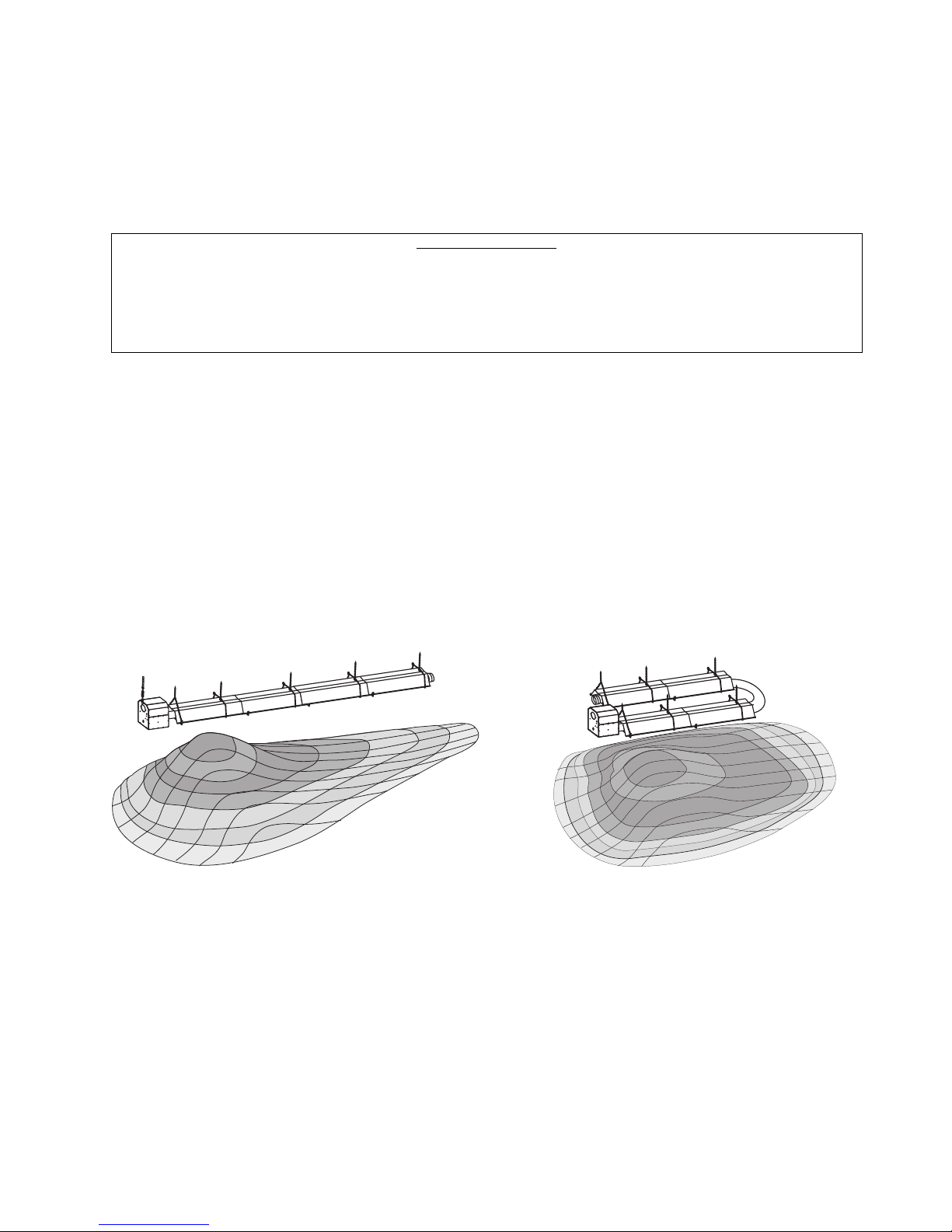
SPS Series Only: Since straight tube heaters are always hotter at the control end than at the flue terminal end,
always observe the minimum recommended mounting heights shown on the specification sheets and in Section
5.0) of this manual. Use U-tube configuration instead of straight tubes for spot or area heating (e.g., where a
single heater is utilized for space heating).
HOT
WARM
High Altitude:
Appliances are supplied as standard for altitudes of O to 2,000 feet (0-610 m). High-altitude ratings are obtained
by a change in the orifice size. When ordered for high altitude installations, burners are supplied by the factory
ready for high altitude installation. Check the nameplate for altitude before proceeding with the installation. In
Canada the adjustment for altitude is made in accordance with Standard CGA 2.17, Gas-Fired Appliances for Use
at High Altitudes.
WARM
HOT
WARM
WARM
Form #43343320
Mar 09 -3-
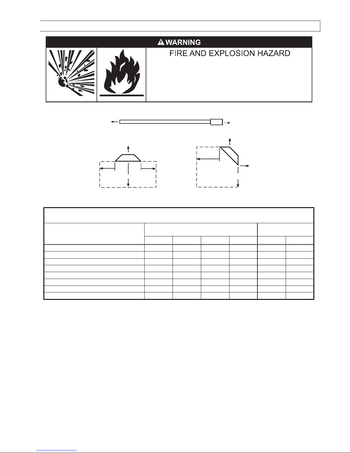
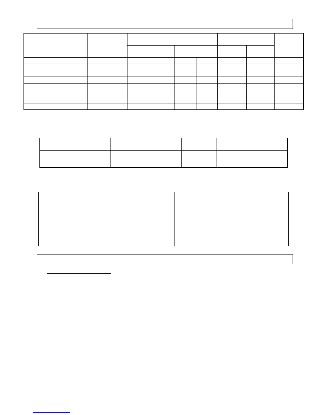
4.0) MINIMUM CLEARANCES TO COMBUSTIBLES
Combustible material must be located outside the
clearance dimensions listed.
Failure to do so may result in death, serious injury or
property damage.
Minimum clearances to combustibles shall be measured from the outer surfaces as shown in the following
diagram:
End
* Ceiling
End
Ceiling
Side
Below
Horizontal
Side
Front
Below
45° Angle (Maximum)
Rear
MINIMUM CLEARANCES TO COMBUSTIBLES
Angle Mounted at
Model No.
Mounted Horizontally
Sides Ceiling* Below Ends 45º Front 45º Rear
45º
SPS/SPU 40 27” 6” 40” 30” 48” 12”
SPS/SPU 50 27” 6” 40” 30” 48” 12”
SPS/SPU 75 27” 6” 60” 30” 48” 12”
SPS/SPU 100 66” 6” 88” ** 40” 66” 20”
SPS/SPU 125 66” 6” 101” ** 40” 66” 20”
SPS/SPU 150 84” 6” 106” ** 48” 84” 24”
SPS/SPU 175 84” 6” 106” ** 48” 84” 24”
SPS/SPU 200 84” 6” 106” ** 48” 84” 24”
* When used indirect vented, minimum clearance for CEILING must be: 12” for SPS/SPU 50-75 and 18” for
SPS/SPU 100-200. If optional corner and u-bend reflectors are not used, the clearance must be 18”.
** Maximum clearance below reduces to 72” once you are 20ft. downstream from the burner box.
▲WARNING: Certain materials or objects, when stored under the heater, will be subjected to radiant heat and
could be seriously damaged. Observe the Minimum Clearances to Combustibles listed in the manual and on the
heater at all times.
NOTE:
1. The clearances specified above must be maintained to combustibles and other materials that may be
damaged by temperatures 90ºF above ambient temperature. Clearances to combustibles are posted on the
burner box. In areas used for storage of combustible materials where they may be stacked below the heater,
NFPA54 requires that the installer must post signs that will “specify the maximum permissible stacking height
to maintain the required clearances from the heater to combustibles.” SunStar recommends posting these
signs adjacent to the heater thermostat or other suitable location that will provide enhanced visibility.
2. The stated clearance to combustibles represents a surface temperature of 90 ºF (32 ºC) above room
temperature. Building materials with a low heat tolerance (such as plastics, vinyle siding, canvas, tri-ply, etc.)
may be subject to degradation at lower temperatures. It is the installer’s responsibility to assure that adjacent
materials are protected from degradation.
-4- Mar 09
Form #43343320
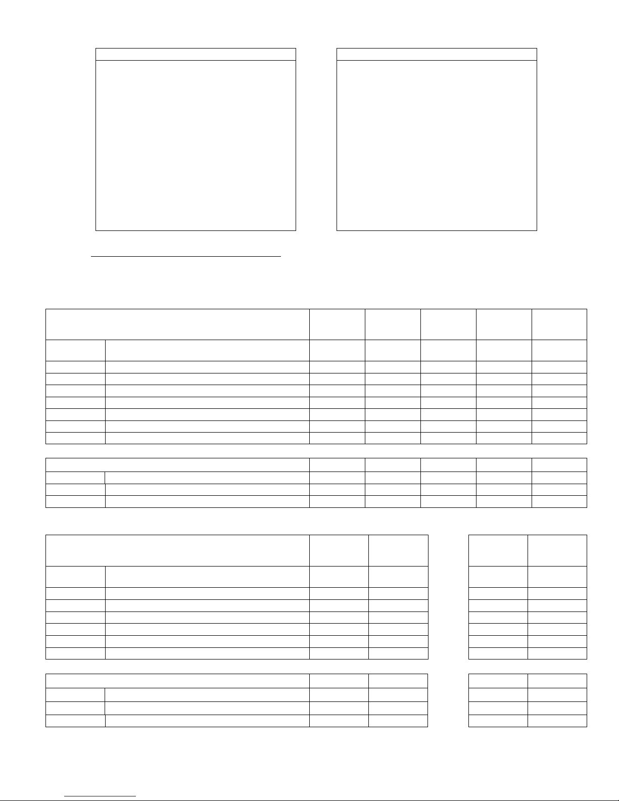
5.0) SPECIFICATIONS
Minimum *
Combustion Air
Plate
Part #
Natural Gas Propane Gas @ Horizontal @ 45º Angle
Model No.
Btu/hr
Input
SPS/SPU 40 40,000 #44140061 #32 (0.116) #49 (0.073) 10 ft. 9 ft. 4
SPS/SPU 50 50,000 #44140064 3.5mm (0.138) 46 (0.081) 11 ft. 10 ft. 5
SPS/SPU 75 75,000 #44140063 #21 (0.159) 2.5mm (0.098) 13 ft. 12 ft. 5
SPS/SPU 100 100,000 #44140062 #12 (0.189)) #32 (0.116) 14 ft. 13 ft. 3
SPS/SPU 125 125,000 #44140066 #4 (0.209) #30 (0.129) 14 ft. 13 ft. 7
SPS/SPU 150 150,000 #44140067 “A” (0.234) #27 (0.144) 15 ft. 14 ft. 4
SPS/SPU 175 175,000 #44140067 “E” (0.250) #23 (0.154) 16 ft. 15 ft. 0
SPS/SPU 200 200,000 #44140068 6.9mm (0.272) 4.1mm (0.161) 18 ft. 16 ft. 1
* MOUNT HEATERS AS HIGH AS POSSIBLE. Minimums are shown as a guideline for human comfort and uniform
energy distribution for complete building heating applications. Consult your SunStar representative for the
particulars of your installation requirements.
Type
Gas
Gas Pipe
Connection
Tube
Diameter
Orifice Size
Flue
Connection
1
Connection1
Fresh Air
Mounting Height
Electrical
Supply
Turbulator
Qty.
Current
Rating
Natural
or Propane
½” MPT
(Male) 4” 4” Round 4” Round
120 Volt, 60Hz,
1 Phase 1.74 Amp
1
See Section 16.0) for vent sizes when multiple heaters are connected into a common vent
Module Electrical Rating: Ignition System (direct spark):
Input Power-Control: 18-30 VAC 50/60 Hz (class 2
transformer)
Input Power-Line: 120 VAC (L1, IND contacts only)
Gas Valve Rating: 2.0 A @ 24 VAC (max.)
Combustion Blower Rating: 3.0 FLA @ 120 VAC
15 second trial for ignition period
15 second pre-purge period
60 second inter-purge period
30 second post-purge period
3 tries for ignition (separate flame sensor).
0.0233 H.P. Motor
Flame Sensitivity: 0.7 microamps minimum
6.0) PACKING LIST
A. SPS/SPU Burner Package
Part Description QTY
Burner Box Assembly (Refer to the following chart for Package Part Numbers) ..........................1
4”ID x 4”Lg Flue Adapter Collar (#30504500) ..................................................................................1
Fastener Kit – Burner Box Attachment/Flue Adapter Collar (#42907040) ..................................1
Containing: #10 x 1/2” Self-Drilling Screws (#02189020) ....................................................2
¼ - 20 Locknuts (#02167010) ..............................................................................3
Tube Flange Gasket (#42921000)...........................................................................1
Turbulator 24” Long (#44152240) *See chart above for required quantities. ..............................*
Installation & Operation Instructions .................................................................................................... 1
Turnbuckle (#43343320).........................................................................................................................1
Gas connector 5/8” OD x 36” (#30302360) ........................................................................................1
Form #43343320
Mar 09 -5-
BURNER PACKAGE NUMBERS
NATURAL GAS PROPANE GAS
MODEL NO. PART NO. MODEL NO. PART NO.
SPS/U 40-N5........................ #44150010 SPS/U 40-L5 .........................#44150020
SPS/U 50-N5........................ #44150030 SPS/U 50-L5 .........................#44150040
SPS/U 75-N5........................ #44150050 SPS/U 75-L5 .........................#44150060
SPS/U 100-N5 ..................... #44150070 SPS/U 100-L5.......................#44150080
SPS/U 125-N5 ..................... #44150090 SPS/U 125-L5.......................#44150100
SPS/U 150-N5 ..................... #44150110 SPS/U 150-L5.......................#44150120
SPS/U 175-N5 ..................... #44150130 SPS/U 175-L5.......................#44150140
SPS/U 200-N5 ..................... #44150150
SPS/U 200-L5.......................#44150160
B. SPS 40-200 Body Package Descriptions
(Package Part Number is indicated on the outside of each corresponding carton.)
20 Ft. pkg
44135000
20Ft.
System
10Ft.
Systems
SPS Body Packages – Aluminized/Hot Rolled or
Alumi-Therm/Hot Rolled
Part # Each Body Package Includes: Qty. Qty. Qty. Qty. Qty.
42912080 10 Ft. Tube with 24 Hole Flange (Aluminized) 1 1 1 - 42912169 10 Ft. Tube with 6 Hole Flange (Alumi-Therm) - - - 1 1
41932101 10 Ft. Tube less Flanges (Hot Rolled) - 1 2 3 4
43319100 Reflector, 9’ 11½” 1 2 3 4 5
30462980 Tube Coupling - 1 2 3 4
43318000 Tube Hanger/Support Bracket, 13” 1 2 3 4 5
43980010 Wire Hanger 1 2 3 4 5
System
10 Ft. pkg
44134020
System
30 Ft. pkg
44136000
30Ft.
System
40 Ft. pkg
44137100
40Ft.
System
50 Ft. pkg
44138100
50Ft.
Body Fastener Kit (included in body packages) 42907280 42907190 42907200 42907210 42907220
42873000 U-Bolt 1 2 3 4 5
02127110 Hex Nut, 5/16-18 3 5 6 8 10
02189020 HWHSM Screw, #10-16 x ½” TEKS 4 8 10 14 18
Systems 60Ft. System 70Ft. System
SPS Body Packages – Alumi-Therm/Hot Rolled
Part # Each Body Package Includes: Qty. Qty. Qty. Qty.
42912169 10 Ft. Tube with 6 Hole Flange (Alumi-Therm) 1 - 1 41932101 10 Ft. Tube less Flanges (Hot Rolled) 3 2 3 3
43319100 Reflector, 9’ 11½” 4 2 4 3
30462980 Tube Coupling 3 2 3 3
43318000 Tube Hanger/Support Bracket, 13” 4 2 4 3
43980010 Wire Hanger 4 2
Body Fastener Kit (included in body packages) 42907210 42907190 42907210 42907200
42873000 U-Bolt 4 2 4 3
02127110 Hex Nut, 5/16-18 8 5 8 6
02189020 HWHSM Screw, #10-16 x ½” TEKS 14 8
40 Ft. Pkg
44137100
20 Ft. Pkg
44135010
40 Ft. Pkg.
44137100
4 3
30 Ft. Pkg
44136040
-6- Mar 09
14 10
Form #43343320
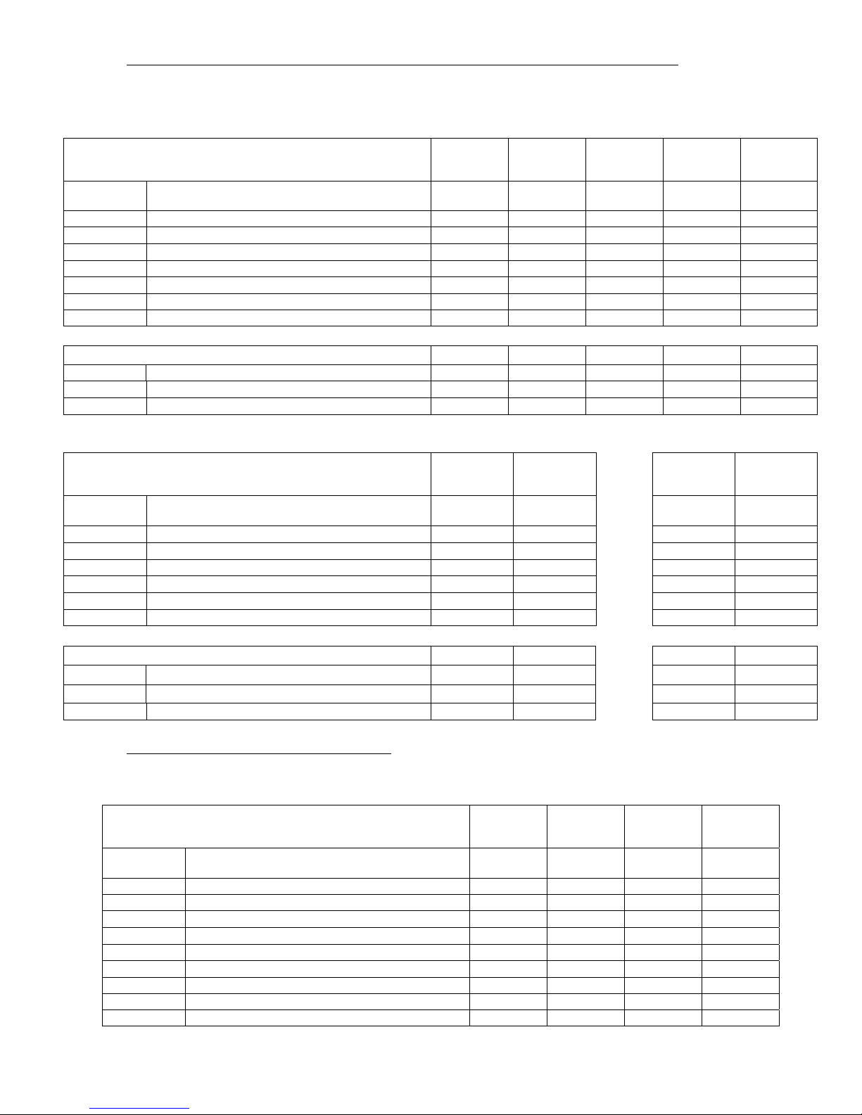
C. SPS 40-200 Series Body Package Descriptions – ALC Option (Aluminized Calorized)
(Package Part Number is indicated on the outside of each corresponding carton.)
Systems
10Ft.
System
20Ft.
System
30Ft.
System
40Ft.
System
50Ft.
System
SPS Body Packages – Aluminized/ Aluminized or
Alumi-Therm/ Aluminized
Part # Each Body Package Includes: Qty. Qty. Qty. Qty. Qty.
42912080 10 Ft. Tube with 24 Hole Flange (Aluminized) 1 1 1 - 42912169 10 Ft. Tube with 6 Hole Flange (Alumi-Therm) - - - 1 1
41932100 10 Ft. Tube less Flanges (Aluminized) - 1 2 3 4
43319100 Reflector, 9’ 11½” 1 2 3 4 5
30462980 Tube Coupling - 1 2 3 4
43318000 Tube Hanger/Support Bracket, 13” 1 2 3 4 5
43980010 Wire Hanger 1 2 3 4 5
10 Ft. pkg
44134020
20 Ft. pkg
44135020
30 Ft. pkg
44136020
40 Ft. pkg
44137090
50 Ft. pkg
44138080
Body Fastener Kit (included in body packages) 42907280 42907190 42907200 42907210 42907220
42873000 U-Bolt 1 2 3 4 5
02127110 Hex Nut, 5/16-18 3 5 6 8 10
02189020 HWHSM Screw, #10-16 x ½” TEKS 4 8 10 14 18
Systems 60Ft. System 70Ft. System
40 Ft. Pkg
SPS Body Packages – Alumi-Therm/ Aluminized
Part # Each Body Package Includes: Qty. Qty. Qty. Qty.
42912169 10 Ft. Tube with 6 Hole Flange (Alumi-Therm) 1 - 1 41932100 10 Ft. Tube less Flanges (Aluminized) 3 2 3 3
43319100 Reflector, 9’ 11½” 4 2 4 3
30462980 Tube Coupling 3 1 3 3
43318000 Tube Hanger/Support Bracket, 13” 4 2 4 3
43980010 Wire Hanger 4 2
44137090
20 Ft. Pkg
44135030
40 Ft. Pkg.
44137090
4 3
30 Ft. Pkg
44136050
Body Fastener Kit (included in body packages) 42907210 42907190 42907210 42907200
42873000 U-Bolt 4 2 4 3
02127110 Hex Nut, 5/16-18 8 5 8 6
02189020 HWHSM Screw, #10-16 x ½” TEKS 14 8
14 10
D. SPU 40-200 Body Package Descriptions
(Package Part Number is indicated on the outside of each corresponding carton.)
Systems
20Ft.
System
30Ft.
System
40Ft.
System
50Ft.
System
SPU Body Packages – Aluminized/Hot Rolled or
Alumi-Therm/Hot Rolled
Part # Each Body Package Includes: Qty. Qty. Qty. Qty.
42912080 10 Ft. Tube with 24 Hole Flange (Aluminized) 1 1 - 42912169 10 Ft. Tube with 6 Hole Flange (Alumi-Therm) - - 1 1
41932101 10 Ft. Tube less Flanges (Hot Rolled) 1 1 3 3
41932051 5 Ft. Tube less Flanges (Hot Rolled) - 2 - 2
43319100 Reflector, 9’ 11½” 2 2 4 4
43319050 Reflector, 4’ 11½” - 2 - 2
30462980 Tube Coupling 1 3 3 5
43318000 Tube Hanger/Support Bracket, 13” 2 4 4 6
43980010 Wire Hanger 2 4 4 6
Form #43343320
Mar 09 -7-
20 Ft. pkg
44135000
30 Ft. pkg
44136010
40 Ft. pkg
44137100
50 Ft. pkg
44138110
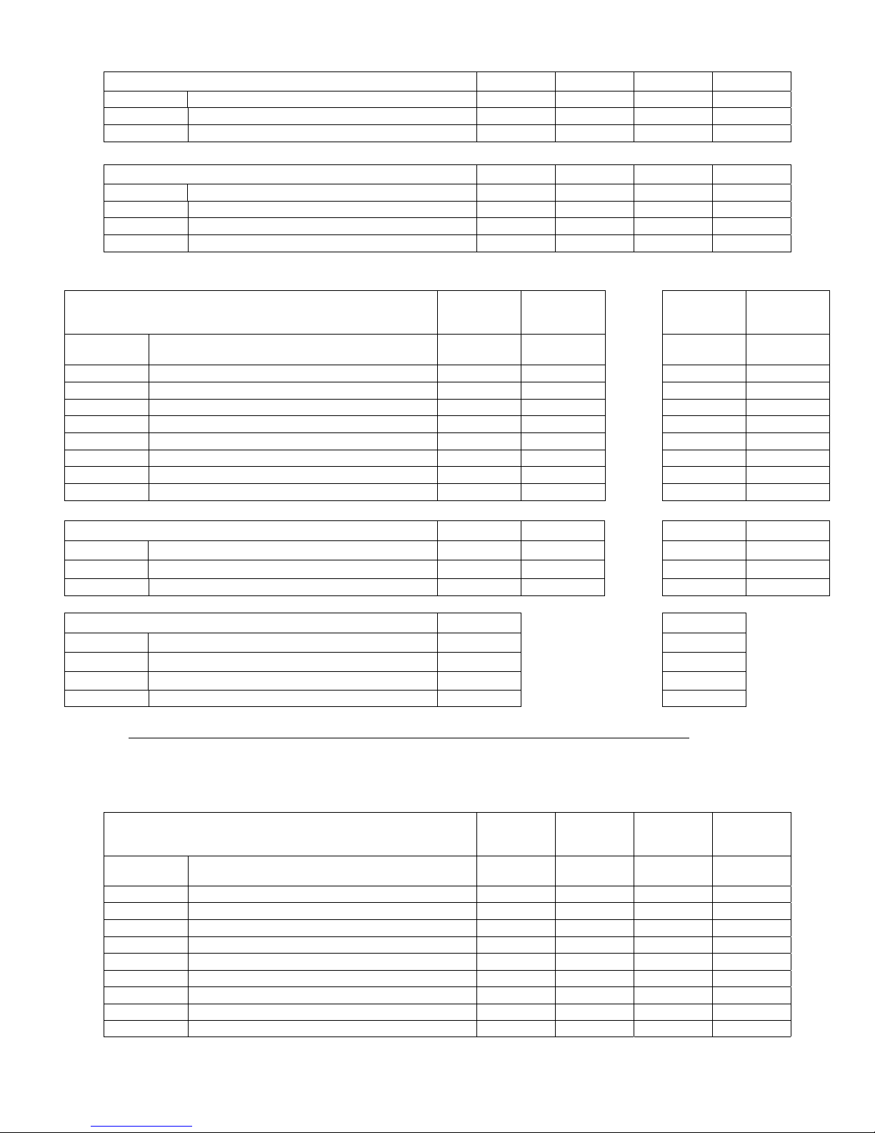
Body Fastener Kit (included in body packages) 42907190 42907210 42907210 42907221
42873000 U-Bolt 2 4 4 6
02127110 Hex Nut, 5/16-18 5 8 8 13
02189020 HWHSM Screw, #10-16 x ½” TEKS 8 14 14 24
U-Bend Package 43208020 43208020 43208020 43208020
42913020 U-Bend 1 1 1 1
43318500 31” Tube Support/Hanger Bracket 1 1 1 1
30462980 Tube Coupling 1 1 1 1
02189020 HWHSM Screw, #10-16 x ½” TEKS 2 2 2 2
Systems 60Ft. System 70Ft. System
40 Ft. Pkg
SPU Body Packages – Alumi-Therm/Hot Rolled
Part # Each Body Package Includes: Qty. Qty. Qty. Qty.
42912169 10 Ft. Tube with 6 Hole Flange (Alumi-Therm) 1 - 1 41932101 10 Ft. Tube less Flanges (Hot Rolled) 3 2 2 3
41932051 5 Ft. Tube less Flanges (Hot Rolled) - - 2 43319100 Reflector, 9’ 11½” 4 2 3 3
43319050 Reflector, 4’ 11½” - - 2 30462980 Tube Coupling 3 2 4 3
43318000 Tube Hanger/Support Bracket, 13” 4 2 5 3
43980010 Wire Hanger 4 2
44137100
20 Ft. Pkg
44135010
40 Ft. Pkg.
44137120
5 3
30 Ft. Pkg
44136040
Body Fastener Kit (included in body packages) 42907210 42907190 42907220 42907200
42873000 U-Bolt 4 2 5 3
02127110 Hex Nut, 5/16-18 8 5 10 6
02189020 HWHSM Screw, #10-16 x ½” TEKS 14 8
U-Bend Package 43208020
42913020 U-Bend 1 1
43318500 31” Tube Support/Hanger Bracket 1 1
30462980 Tube Coupling 1 1
02189020 HWHSM Screw, #10-16 x ½” TEKS 2
E. SPU 40-200 Series Body Package Descriptions – ALC Option (Aluminized Calorized)
(Package Part Number is indicated on the outside of each corresponding carton.)
20Ft.
Systems
System
30Ft.
System
43208020
40Ft.
System
18 10
2
50Ft.
System
SPU Body Packages – Aluminized/Aluminized or
Alumi-Therm/Aluminized
Part # Each Body Package Includes: Qty. Qty. Qty. Qty.
42912080 10 Ft. Tube with 24 Hole Flange (Aluminized) 1 1 - 42912169 10 Ft. Tube with 6 Hole Flange (Alumi-Therm) - - 1 1
41932100 10 Ft. Tube less Flanges (Aluminized) 1 1 3 3
41932050 5 Ft. Tube less Flanges (Aluminized) - 2 - 2
43319100 Reflector, 9’ 11½” 2 2 4 4
43319050 Reflector, 4’ 11½” - 2 - 2
30462980 Tube Coupling 1 3 3 5
43318000 Tube Hanger/Support Bracket, 13” 2 4 4 6
43980010 Wire Hanger 2 4 4 6
20 Ft. pkg
44135020
-8- Mar 09
30 Ft. pkg
44136030
40 Ft. pkg
44137090
50 Ft. pkg
44138090
Form #43343320
6
(15cm)
12
(30cm)
END REFLECTOR
13
(33cm)
13
(33cm)
Body Fastener Kit (included in body packages) 42907190 42907210 42907210 42907221
42873000 U-Bolt 2 4 4 6
02127110 Hex Nut, 5/16-18 5 8 8 13
02189020 HWHSM Screw, #10-16 x ½” TEKS 8 14 14 24
U-Bend Package 43208020 43208020 43208020 43208020
42913020 U-Bend 1 1 1 1
43318500 31” Tube Support/Hanger Bracket 1 1 1 1
30462980 Tube Coupling 1 1 1 1
02189020 HWHSM Screw, #10-16 x ½” TEKS 2 2 2 2
SPU Body Packages – Alumi-Therm/Hot Rolled
60Ft. System 70Ft. System
40 Ft. Pkg
44137090
20 Ft. Pkg
44135030
40 Ft. Pkg.
44137110
30 Ft. Pkg
44136050
Part # Each Body Package Includes: Qty. Qty. Qty. Qty.
42912169 10 Ft. Tube with 6 Hole Flange (Alumi-Therm) 1 - 1 41932100 10 Ft. Tube less Flanges (Aluminized) 3 2 2 3
41932050 5 Ft. Tube less Flanges (Aluminized) - - 2 43319100 Reflector, 9’ 11½” 4 2 3 3
43319050 Reflector, 4’ 11½” - - 2 30462980 Tube Coupling 3 2 4 3
43318000 Tube Hanger/Support Bracket, 13” 4 2 5 3
43980010 Wire Hanger 4 2
5 3
Body Fastener Kit (included in body packages) 42907210 42907190 42907220 42907200
42873000 U-Bolt 4 2 5 3
02127110 Hex Nut, 5/16-18 8 5 10 6
02189020 HWHSM Screw, #10-16 x ½” TEKS 14 8
U-Bend Package 43208020
42913020 U-Bend 1 1
43318500 31” Tube Support/Hanger Bracket 1 1
30462980 Tube Coupling 1 1
02189020 HWHSM Screw, #10-16 x ½” TEKS 2
18 10
43208020
2
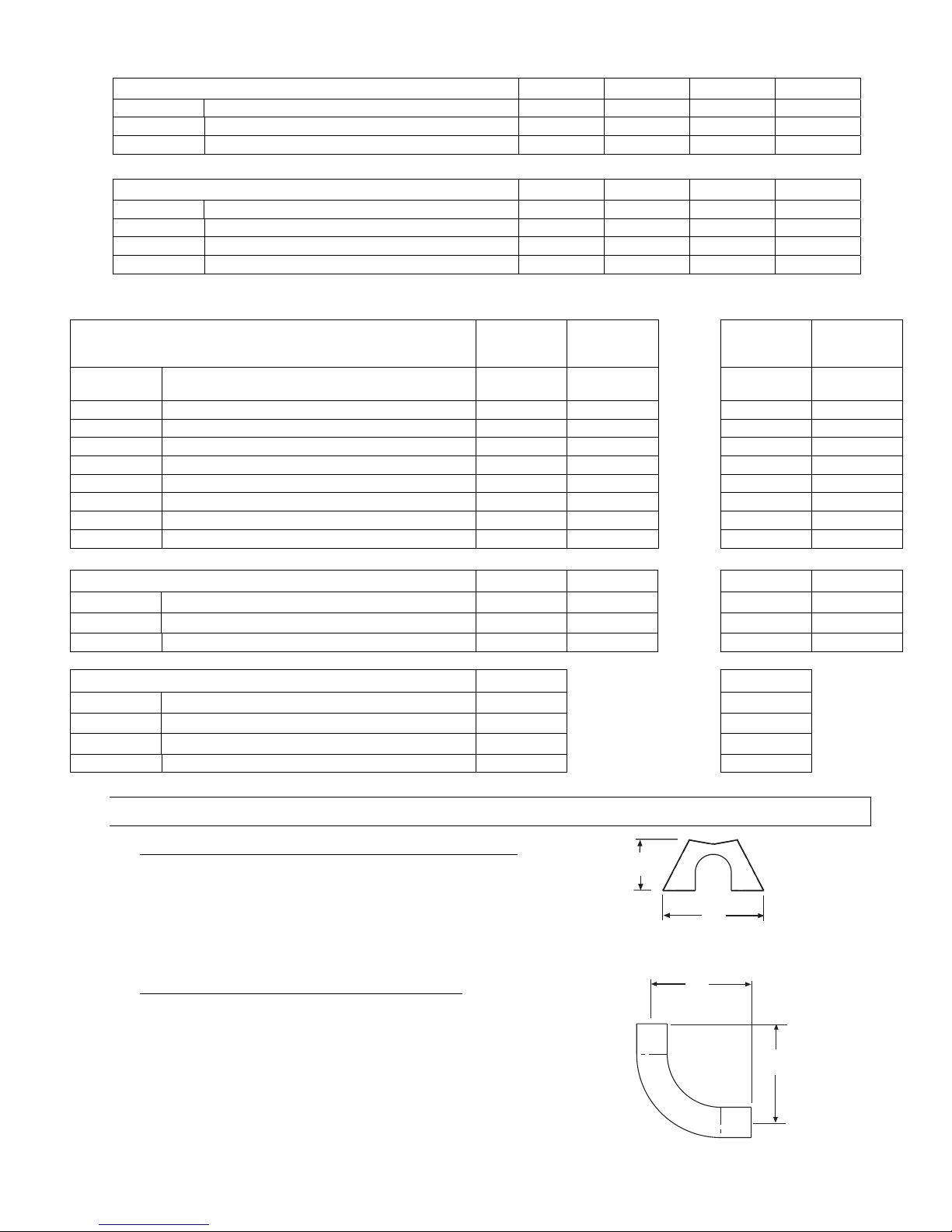
6.1) ACCESSORY PACKAGES
A. End Reflector Accessory Package, Part #43341010
(1 pkg. per SPS Series or 2 pkgs. per SPU Series)
Contains:
End Reflector, #43320000……QTY–2
Speed Clips, #02266010……QTY–8
B. Elbow Accessory Package, Part #43208010
(Option for SPS Series Only)
Contains:
Form #43343320
Mar 09 -9-
Elbow, #43175000……QTY–1
#10-16 x ½ Self-Drilling Screws, #02189020……QTY–2
Tube Coupling, #30462980……QTY–1
18
(46cm)
30 3/4 (78cm)
Length = 24 (61cm)
18
(46cm)
Tube Centers
31
(79cm)
4 (10cm)
7 1/2
(19cm)
3 3/4 (10cm)
3 1/2 (9cm)
7 1/2
(19cm)
Bird
Screen
Side View
Front View
C. Corner Reflector Accessory Package, Part #43342000
(Option for SPS Series Only)
Contains:
Corner Reflector Assembly, #43345000……QTY–1
Speed Clips, #02266010……QTY–4
D. U-Bend Package, Part #43208020
(Option for SPU Series Only)
Contains:
U-Bend, #42913020……QTY–1
#10-16 x ½ Self-Drilling Screws, #02189020……QTY–2
Tube Coupling, #30462980……QTY–1
31” Tube Support/Hanger Bracket, #43318500……QTY–1
24
(61cm)
24
(61cm)
E. U-Bend Reflector Package, Part #43488000
(Option for SPU Series Only)
Contains:
U-Bend Reflector, #43490000……QTY–1
U-Bend End Reflector, #43490050……QTY–1
Speed Clips, #02266010……QTY–11
#10-16 x ½ Self-Drilling Screws, #02189020……QTY–4
Installation Form, #43489000……QTY-1
F. 31” Hanger/Tube Support, Part #43318500
(Option for Angle Mounting of SPU Series)
G. Exhaust Hood Package, Part #42924000
Contains:
Exhaust Hood Assembly, #42925540……QTY–1
#8-18 x ½ Self-Drilling Screws, #02189030……QTY–2
-10- Mar 09
Form #43343320

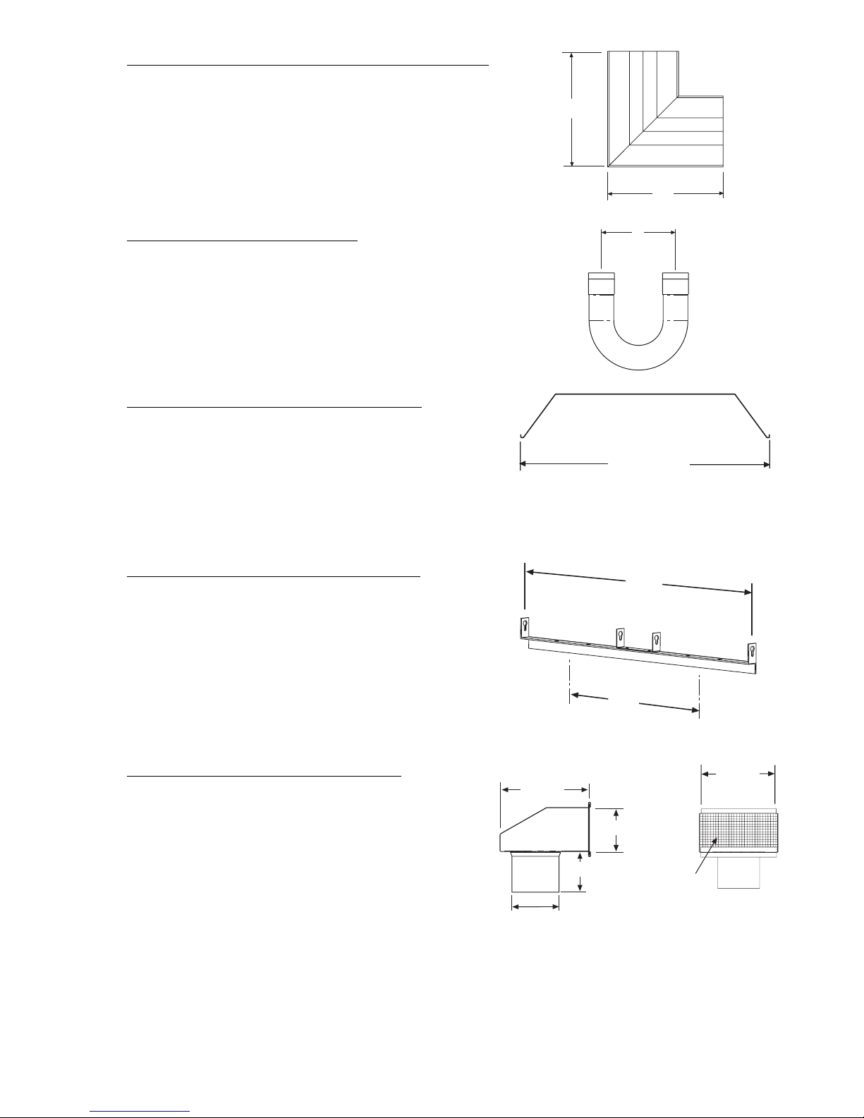
7.0) TYPICAL LAYOUTS – SPS/SPU SERIES
10FT.
SYSTEM
50 FT.
SYSTEM
20 FT.
SYSTEM
30 FT.
SYSTEM
60 FT.
SYSTEM
40 FT.
SYSTEM
LEGEND
Burner Box
Flue Termination
10 FT. Body Section
5 FT. Body Section
90 Deg. Elbow
180 Deg. U-Bend
70 FT.
SYSTEM
MODEL
EMITTER LENGTH BODY LENGTH
Min. Max.
MODEL
Min. Max.
SPS 40 10 Ft. 20 Ft. SPU 40 10 Ft. 10 Ft.
SPS 50 20 Ft 30 Ft. SPU 50 10 Ft. 15 Ft.
SPS 75 20 Ft. 30 Ft. SPU 75 10 Ft. 15 Ft
SPS 100 30 Ft. 40 Ft. SPU 100 15 Ft. 20 Ft.
SPS 125 30 Ft 50 Ft. SPU 125 15 Ft. 25 Ft.
SPS 150 40 Ft. 60 Ft. SPU 150 20 Ft. 30 Ft.
SPS 175 50 Ft. 70 Ft. SPU 175 25 Ft. 35 Ft.
SPS 200 50 Ft. 70 Ft. SPU 200 25 Ft. 35 Ft.
NOTES:
1. In all configurations, the control unit must be connected directly to either a) the 24-hole flange of the 10 ft.
aluminized steel starting body section (for 10 ft., 20 ft., and 30 ft. systems) or b) the 6-hole flange of the 10
ft. alumi-therm steel starting body section (for 40 ft., 50 ft., 60 ft., and 70 ft. systems).
2. Joining of two 90º elbows directly together to form a “Z” shape IS NOT permitted.
3. SPS / U 175 - 40 ft length available for special applications.
4. 5 Ft. Body Packages may be utilized on any of these heaters to yield heater lengths from 15 ft. to 70 ft.
5. Any configuration of components not shown in the illustrations may be used except as noted in 1 and 2
above.
Form #43343320
Mar 09 -11-
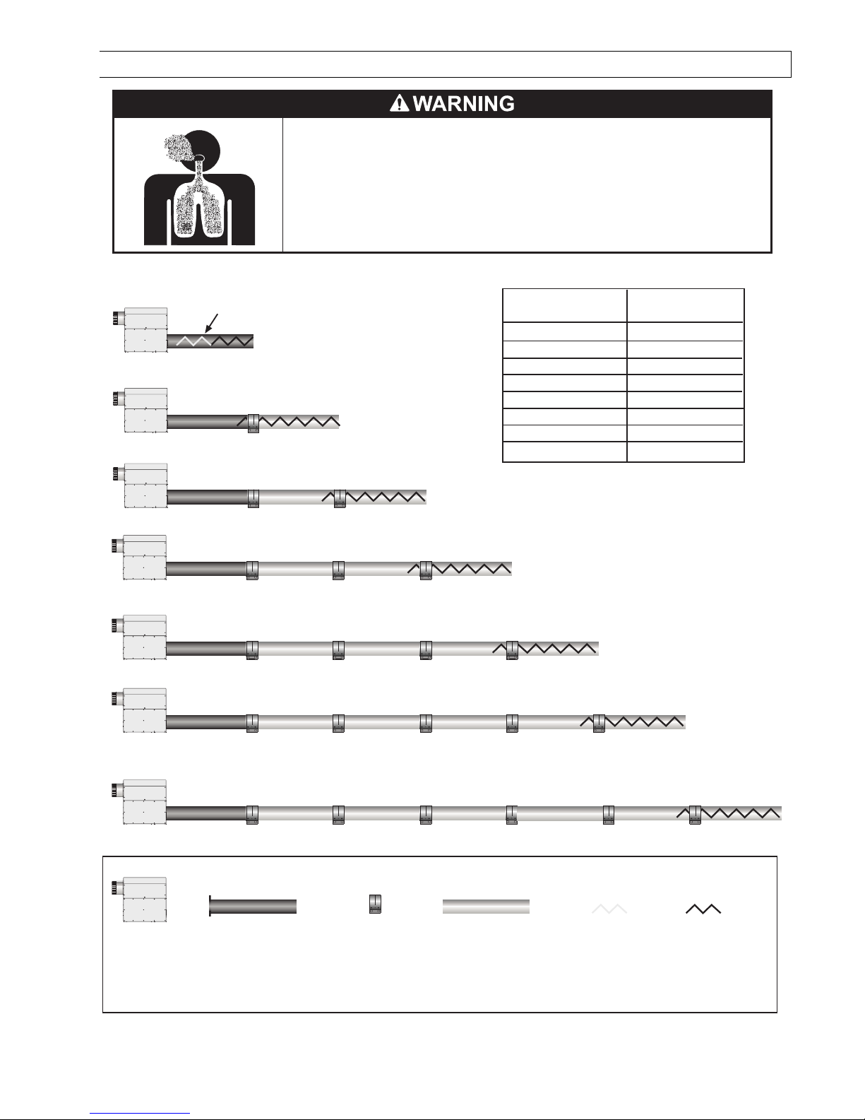
7.1) TYPICAL ASSEMBLY LAYOUT
POISONOUS GAS AND SOOT HAZARD
The heater must be assembled with the correct number of turbulator sections
and tube length for the rated heat input.
The turbulator must be installed in the last tube section as shown.
Failure to do so may result in death, serious injury, property damage or illness
from Carbon Monoxide poisoning.
10 FT. SYSTEM
20 FT. SYSTEM
30 FT. SYSTEM
40 FT. SYSTEM
50 FT. SYSTEM
60 FT. SYSTEM
Stainless Steel Turbulator closest
to burner SPS/U 40 only.
Model
SPS/U 40
SPS/U 50
SPS/U 75
SPS/U 100
SPS/U 125
SPS/U 150
SPS/U 175
SPS/U 200
2 Ft. Turbulator
Sections
4
5
5
3
7
4
0
1
70 FT. SYSTEM
Burner Box 10ft Aluminized Tube 24
Hole Flange
or
10ft Alumi-Therm Tube
6 Hole Flange
LEGEND
Coupling 10ft Aluminized or HRS
Tube model dependent
-12- Mar 09
2ft Stainless
Steel
Turbulator
sections
2ft Aluminized
Steel
Turbulator
sections
Form #43343320
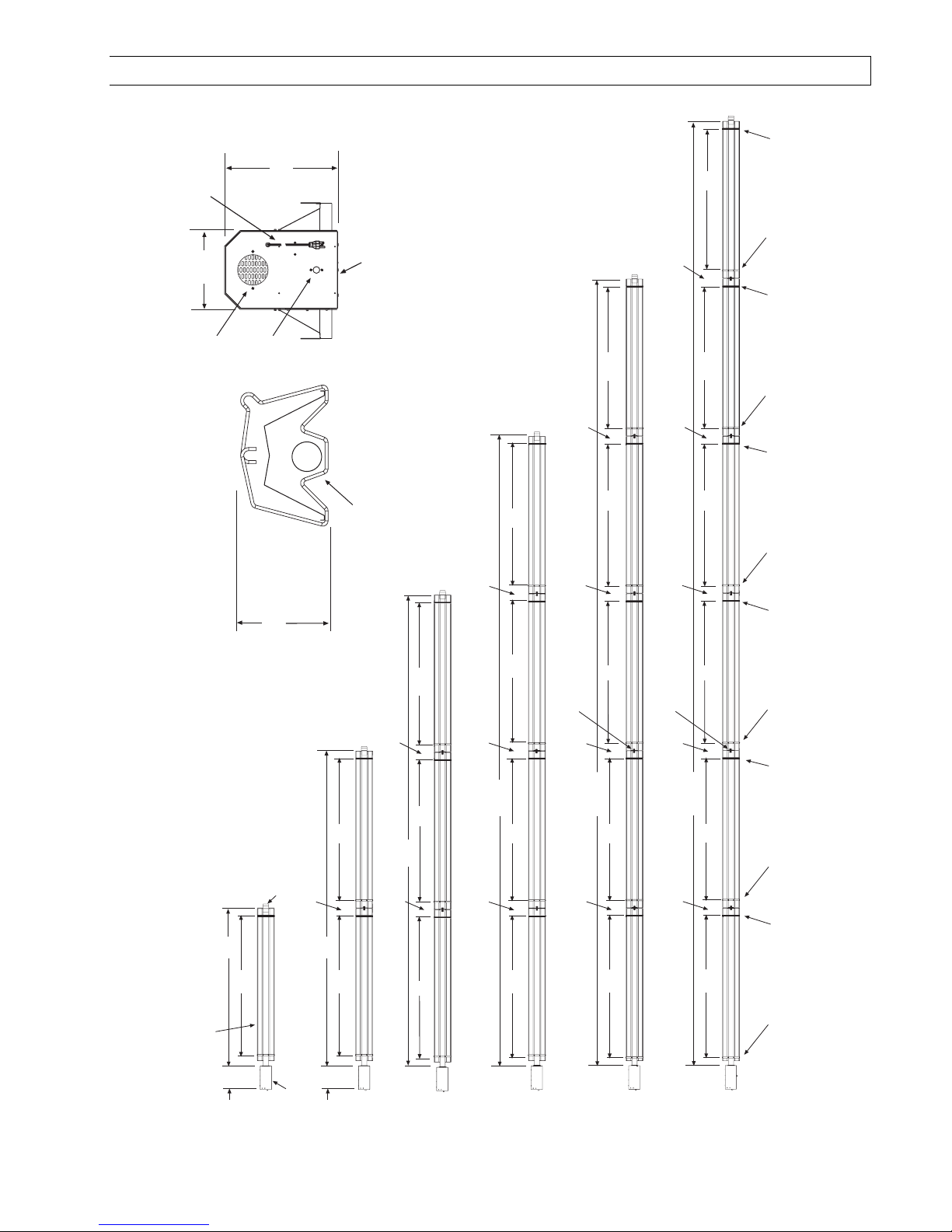
8.0) DIMENSIONS – SPS SERIES
Typical Dimensions Up to 60 Ft. Shown.
120VAC
Power Supply Cord
10
(25cm)
Fresh Air
Inlet
1/2 MPT Gas
(37cm)
14-1/2
Connection
Burner
Box
End View
Flue Terminal
12
(30cm)
108
(274cm)
12
12
(30cm)
(30cm)
108
(274cm)
108
(274cm)
12
12
(30cm)
(30cm)
108
108
(274cm)
108
(274cm)
(274cm)
Wire Hanger
13 Tube Support/
Hanger Bracket
Wire Hanger
13 Tube Support/
Hanger Bracket
Wire Hanger
13 Tube Support/
Hanger Bracket
10 FT Tube
Assembly
120
(typical)
(305cm)
108
(274cm)
9-1/4
(24cm)
Flue
Terminal
12
(30cm)
240
(610cm)
108
(274cm)
108
(274cm)
12
12
(30cm)
360
(30cm)
108
(274cm)
108
(274cm)
(914cm)
108
(274cm)
12
12
(30cm)
480
(30cm)
108
(274cm)
(1219cm)
108
(274cm)
108
(274cm)
108
4 Tube Coupling
(typical)
12
(30cm)
600
(1524cm)
108
12
(30cm)
108
(274cm)
(274cm)
(274cm)
4 Tube Coupling
(typical)
12
(30cm)
720
12
(30cm)
Bottom View
108
(274cm)
(1829cm)
108
(274cm)
108
(274cm)
13 Tube Support/
Wire Hanger
Bottom View
Wire Hanger
Hanger Bracket
13 Tube Support/
Hanger Bracket
Wire Hanger
13 Tube Support/
Hanger Bracket
Burner
Models:
SPS 40
Box
14
(36cm)
Form #43343320
Mar 09 -13-
14
(36cm)
Models:
SPS 40, 50,
75
Models:
SPS 50, 75,
100, 125
Models:
SPS 100, 125
150
Models:
SPS 125,
150, 175, 200
Models:
SPS 150,
175, 200

8.1) DIMENSIONS – SPU SERIES
Typical Dimensions Up to 50 Ft. Shown.
(36cm)
Models:
SPU 40, 50,
75
Models:
SPU 50, 75,
100, 125
Models:
SPU 100, 125,
150, 175
14
(274cm)
Burner
Box
Flue
Terminal
108
180
(457cm)
(274cm)
120
(305cm)
108
(274cm)
108
240
(610cm)
12
(30cm)
12
(30cm)
15
(38cm)
10 FT Tube
Assembly
(typical)
5 FT Tube
Assembly
48
(122cm)
U-Bend
108
(274cm)
Models:
SPU 125, 150,
175, 200
6
(16cm)
108
(274cm)
Bottom View
31 Tube Support/
Hanger Brackets
(typical at control end)
Shipped with
U-Bend Package
(30cm)
Wire Hangers
(typical)
12
300
(762cm)
13 Tube Support/
Hanger Brackets
(typical)
Fresh Air
Inlet
1/2 MPT Gas
Connection
108
(274cm)
Wire Hangers
(typical)
10
(25cm)
4 Tube Coupling
(typical)
12
(30cm)
48
(122cm)
13 Tube Support/
Hanger Brackets
(typical)
120VAC
Power Supply Cord
14-1/2
(37cm)
31 Tube Support/
Hanger Bracket
Flue Terminal
U-Bend
18 (46cm)
Burner
Box
31 (79cm)
End View
-14- Mar 09
Form #43343320
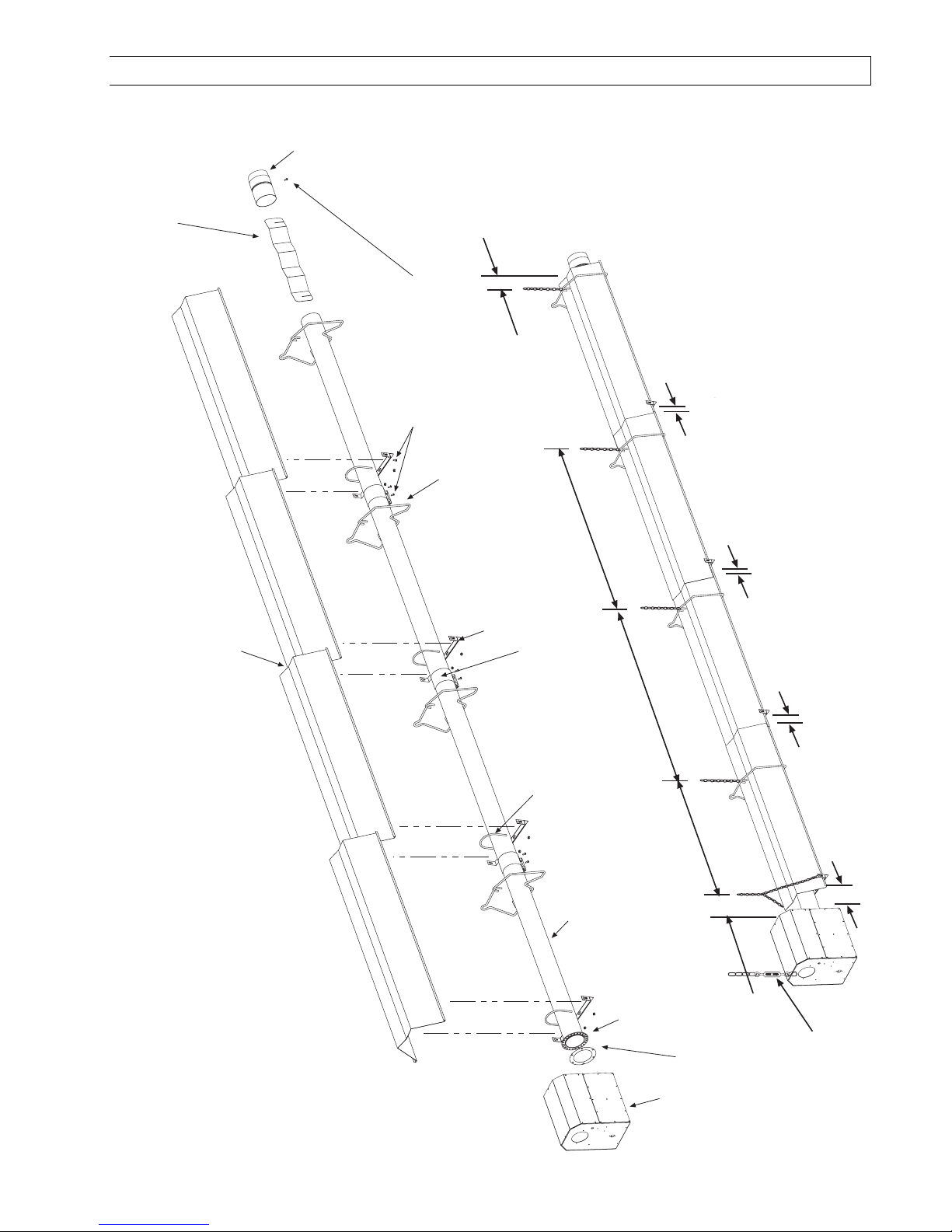
8.2) HEATER ASSEMBLY / JOINING OF TUBE SECTIONS
Flue
Terminal
Turbulator
(See specifications
section 5 for required
quantities.)
Not Less
Than 10
#10 Self-Drill Screws
(Typical all tube supports,
tube couplings and flue
terminal.)
)
.
Wire Hanger
8 - 10
overlap
1
overlap
1
Typical
Overlap
40FT Shown)
Tube Support Bracket
Tube Coupling
(Typical each tube joint
U-Bolt Clamp &
5/16" Hex Nuts
8 - 10
Tube
7
4"OD x 10Ft.
for required tubes.
See section
Flange
24 Hole for Aluminized Steel Tubes
Mounting
6 Hole for Alumi-Therm Steel Tubes
8 - 9 ¼
Gasket
overlap
2
5 hanging points to be used for suspension for a typical 40ft
long system. There must be two hanging points on the first
tube and one on each of the other tubes
box to reflector)
burner
3
(
SPS
(
Typical Assembly Overview
Form #43343320
Mar 09 -15-
Burner
Box
Burner Box
Suspension
Chain
Maximum 6 distance
from control box to the
tube support/hanger
bracket.

Typical Assembly Overview
(SPU 40FT Shown)
Turbulator
(See specifications
section 5 for required
quantities.)
#10 Self-Drill
Screws
(2 each)
Flue
Terminal
Burner Box
Gasket
Typical
Overlap
31 Tube Support Brk.
with U-Bolt Clamp
& 5/16" Hex Nuts
Mounting Flange
24 Hole for Aluminized Steel Tubes
6 Hole for Alumi-Therm Steel Tubes
Reflector
Wire Hanger
4"OD x 10Ft. Tube
See section 7
for required tubes.
13 Tube Support Brk.
with U-Bolt Clamp
& 5/16" Hex Nuts
U-Bend
Tube Coupling
(Typical each tube joint.)
#10 Self-Drill Screws
(Typical all tube supports,
tube couplings and flue
terminal.)
Maximum 6 distance
from burner box to the
tube support/hanger
bracket.
Burner Box
Suspension
Chain
8 - 10
8 - 9 ¼
6 hanging points to be used for suspension for a typical
40ft long system. There must be two hanging points
on the first tube and one on each of the other tubes
-16- Mar 09
Form #43343320
 Loading...