

SunStar SPS/E-BH6100, SPC/E-BH6100-01, SPC/E-BH6100-02 User Manual

1) FOR AT MOST USE WITH EASINESS,
PLEASE CERTAINLY READ THIS MANUAL
BEFORE STARTING USE.
2) KEEP THIS MANUAL IN SAFE PLACE
FOR REFERENCE WHEN THE MACHINE
BREAKS DOWN.
MMEEEE--110000220033
USER
’’
S MANUAL
SPS/E-BH6100
R
SSuunnSSttaarr CCOO..,, LLTTDD..
Direct Drive, Electronically
Controlled Lock Stitch
Button Hole Sewing Machine
(Electronic Control Part)

Best Quality
Best Price
Best Service
SSUUNNSSTTAARR CCOO..,, LLTTDD..
R
1.
Thank you for purchasing our product. Based on the rich expertise and
experience accumulated in industrial sewing machine production, SUNSTAR
will manufacture industrial sewing machines, which deliver more diverse
functions, high performance, powerful operation, enhanced durability, and
more sophisticated design to meet a number of user’s needs.
2. Please read this user’s manual thoroughly before using the machine. Make
sure to properly use the machine to enjoy its full performance.
3. The specifications of the machine are subject to change, aimed to enhance
product performance, without prior notice.
4.
This product is designed, manufactured, and sold as an industrial sewing
machine. It should not be used for other than industrial purpose.
Eyelet Button Hole Sewing Machine Model
SPS/E-BH6100 -
④
Sub-type
01: Long thread trimming
02: Short thread trimming
③
Eyelet Button Hole
Mode Name
①
Sunstar
Pattern
System
②
Series

Table of Contents
1. Machine Safety Regulations
.......................................................................................... 6
2. Specifications
................................................................................................................ 9
3. Power Voltage Connection
........................................................................................... 10
3-1) Power Voltage and Power Cord .................................................................................................................................. 10
3-2) How to Change Power Voltage.................................................................................................................................... 11
4. Cable Connection to Control Box .......................................................................................... 12
4-1) Internal wiring of the control box ................................................................................................................................ 12
4-2) External wiring of the control box ............................................................................................................................... 12
5. Fuse Exchange ...................................................................................................... 13
6. Use the Operational Panel and Perform Sewing ........................................................ 14
6-1) Operational panel and keys .......................................................................................................................................... 14
1) Operational panel...................................................................................................................................................... 14
2) Initial display............................................................................................................................................................. 15
3) Sewing mode............................................................................................................................................................. 15
4) Knife operation ........................................................................................................................................................ 16
5) Clamp operation........................................................................................................................................................ 16
6) Needle bar forward/backward adjustment after sewing suspension .................................................................... 16
7) Menu overview ........................................................................................................................................................ 17
8) A button hole structure ............................................................................................................................................ 18
9) Change the pattern number .................................................................................................................................... 19
10) Adjusting the thread tension .................................................................................................................................. 19
11) Function keys.......................................................................................................................................................... 20
12) A front / rear knife motion..................................................................................................................................... 20
13) Threading Mode ..................................................................................................................................................... 21
14) Check Mode ........................................................................................................................................................... 21
6-2) Change the pattern data information ........................................................................................................................... 23
1) Change the pattern data information and the initial screen .................................................................................. 23
2) Change the speed ..................................................................................................................................................... 23
6-3) Create the basic pattern shapes..................................................................................................................................... 26
6-3-1) T aper pattern ..................................................................................................................................................... 26
1) Create the up bartack shape.......................................................................................................................... 27
2) Create the zigzag shape................................................................................................................................. 29
3) Create the down bartack shape..................................................................................................................... 30
4) Create the pattern data .................................................................................................................................. 31
6-3-2) Square bartack pattern ..................................................................................................................................... 32
1) Create the up bartack shape ....................................................................................................................... 33
2) Create the zigzag shape ............................................................................................................................... 34
3) Create the down bartack shape ................................................................................................................... 35
4) Create the pattern data ................................................................................................................................. 36
6-3-3) Eyelet shape pattern .......................................................................................................................................... 37
1) Create the up bartack shape ......................................................................................................................... 38
2) Create the pattern data................................................................................................................................... 39

6-4) Set the knife-related parameters .......................................................................................................................... 40
1) Set the number of knives ............................................................................................................................. 40
2) Set the left/right space for knife .................................................................................................................. 41
3) Blade Motion Method Setting ..................................................................................................................... 42
4-1) Blade Position Setting (When the blade motion method is set at‘Sensor’) ......................................... 43
4-2) Blade Position Setting (When the blade motion method is set at ‘T iming’) ....................................... 44
5) Clamp type (sewing size) setting ............................................................................................................... 45
6-5) Compensation of the eyelet part .................................................................................................................................. 46
6-6) Compensation of the zigzag part.................................................................................................................................. 49
6-7) Lower bar tack correction ............................................................................................................................................ 51
6-8) Set the chain sewing-related parameters...................................................................................................................... 53
1) Enable the chain sewing function............................................................................................................................ 53
2) Use the set chain sewing function ........................................................................................................................... 54
3) Disable the chain sewing function........................................................................................................................... 55
6-9) Set the Back-T ack function........................................................................................................................................... 56
6-10) Set the production counter.......................................................................................................................................... 57
1) Enable/Disable the production counter .................................................................................................................. 57
2) Select the production counter (Up or Down Counter) ........................................................................................... 57
3) Make sub-setting for down counter......................................................................................................................... 58
4) The initial screen for production counter setting ................................................................................................... 58
6-11) Use of upper thread nipper device (optional)............................................................................................................ 59
6-12) Changing the sewing start position .......................................................................................................................... 60
6-13) Set the pattern number ‘0’.......................................................................................................................................... 61
1) Original setting.......................................................................................................................................................... 61
2) Initialize the pattern-related parameter defaults ..................................................................................................... 62
6-14) Initialization................................................................................................................................................................. 63
6-15) Machine testing functions .......................................................................................................................................... 63
1) Step motor test (Jog X, Y, Z Test)............................................................................................................................ 64
2) Thread tension solenoid test (Sol Test).................................................................................................................... 65
3) Main motor test (M Motor T est) ............................................................................................................................. 66
4) Encoder test ............................................................................................................................................................. 66
5) Synchro test............................................................................................................................................................... 67
6) Hand switch input test.............................................................................................................................................. 67
7) Auxiliary output test(Aux. Out Test)....................................................................................................................... 68
8) Auxiliary input test(Aux. In T est)............................................................................................................................ 69
7. Exchanging the Program ROM.............................................................................................. 70
7-1) Program ROM Mounting Exchanging........................................................................................................................ 70
7-2) Exactly necessary operation after exchanged the program ROM ............................................................................. 71
8. Error Messages and Troubleshooting ........................................................................ 73
9. Parameter Changing Methods and Classification........................................................ 74
9-1) Parameter numbers related to general sewing (Group A).......................................................................................... 74
9-2) Function numbers related to servo motor control (Group B)..................................................................................... 75
6
11
Machine Safety Regulations
Safety instructions in this manual are defined as Danger, Warning and Caution.
If you do not follow the instructions, physical injuries or machine damage might occur.
Danger : This mark must be observed. Otherwise, danger could result during installation, transportation and operation of the
machine.
Warning : When you keep this indication, injuries caused by the machine can be prevented.
Caution : When you keep this indication, machine errors could be prevented.
1-1) Transportation
Danger
1-2) Installation
Warning
1-3) Repair
Caution
Those who fully understand the safety regulations should transport the machine. The
following instructions must be followed.
ⓐ At least two people should move the machine.
ⓑ To prevent occurrence of accidents during transportation, thoroughly wipe off the oil put on
the surface of the machine.
The machine may not work properly or break down depending on where it is installed. The
right place of installation should meet the following conditions.
ⓐ Remove the package and wrappings from the top in order. Take a special notice of the
nails on the wooden box.
ⓑ Dust and moisture stains and rusts the machine. Install air-conditioners and clean the
machine regularly.
ⓒ Keep the machine away from direct sunlight.
ⓓ Leave the space of at least 50cm between the wall and the left, right and rear sides of the
machine for repairing.
ⓔ Explosion
Do not use the machine in the atmospheres exposed to the danger of explosion.
To avoid explosion, do not operate this machine in a place where a large quantity of
aerosol products is used or where oxygen is stored, unless there are specific facilities
installed to prevent explosion.
ⓕ The machine doesn’t provide lightings. End users should install them at their workplace.
When the machine needs to be repaired, only the designated A/S engineers, who were educated
by Sunstar, should repair the machine.
ⓐ Before cleaning or repairing the machine, turn off the machine and wait for 5 minutes till
the machine is completely discharged.
ⓑ The machine specifications or parts should not be altered without prior consultation with
the company. This may pose a danger to operation.
ⓒ When repairing, only the original spare parts produced by the company should be used for
replacement.
ⓓ Put all the safety covers back on the machine after repairing is complete.
7
SPS/E-BH6100 Series is an industrial sewing machine designed to conduct pattern sewing
using fabrics and other similar materials. During operation, the following instructions should
be kept in mind.
ⓐ Read through this manual carefully and completely before operating the machine.
ⓑ Wear the proper clothes for safety.
ⓒ Keep hands or other parts of the body away from the machine’s operating section
(needle, hook, thread take-up, and pulley, etc.), when the machine is operation.
ⓓ Do not remove safety plates and various covers while the machine is operating.
ⓔ Be sure to connect the grounding conductor.
ⓕ Turn off the machine before opening the electric boxes including control box. Make sure
that the power switch is “OFF”.
ⓖ Stop the machine when placing the thread or when checking the sewing materials.
ⓗ Do not turn on the machine while stepping on the pedal.
ⓘ Do not operate the machine when the cooling pan is clogged. The air filter in the control
box should be cleaned once every week.
ⓙ If possible, install the machine away from the place where powerful electromagnetic
waves are generated such as high-frequency welding machine.
Warning
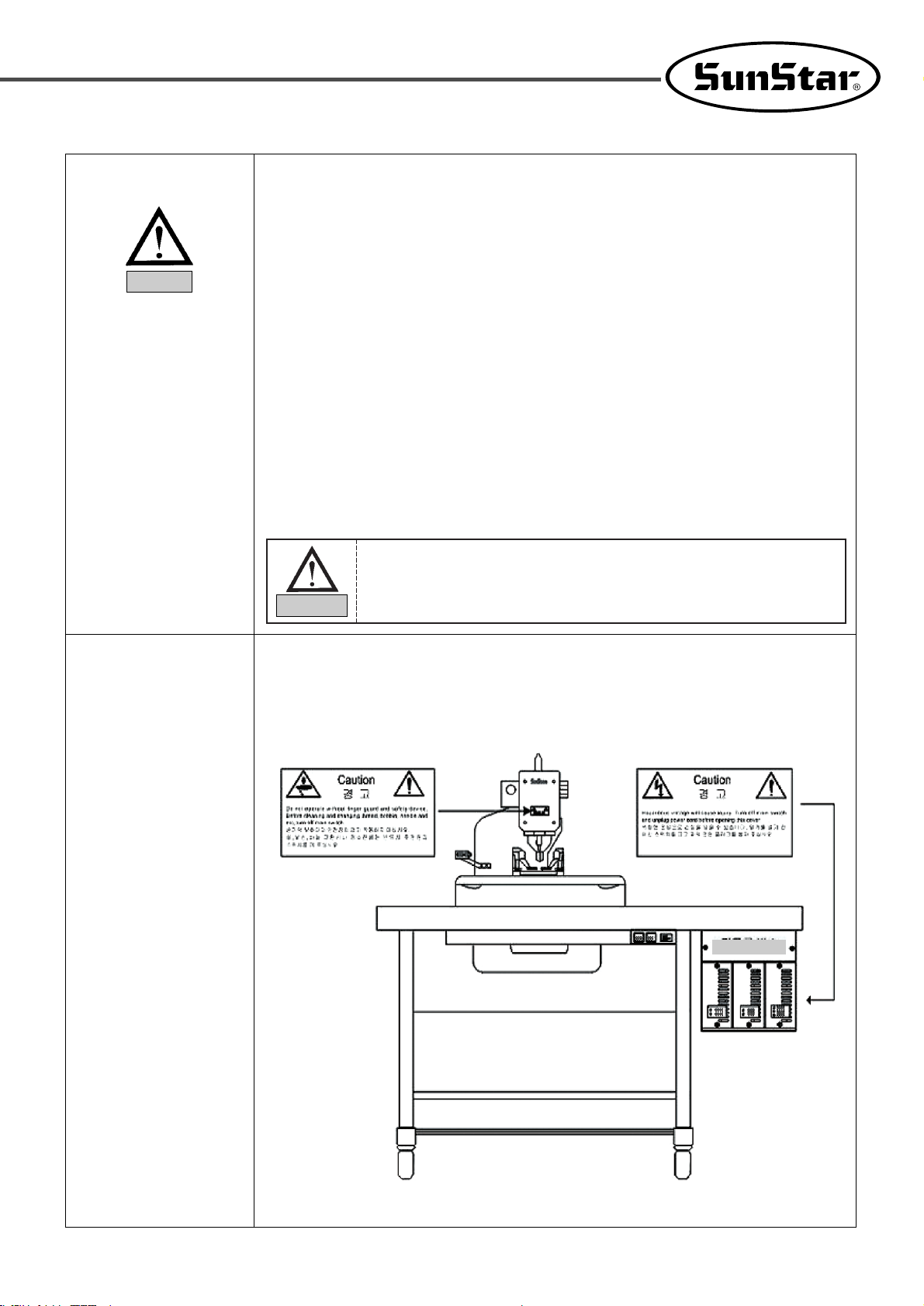
Caution mark is attached on the machine for safety.
When operating the machine, please read the instructions on the mark.
Locations of caution marks(see the front)
1-5) Locations of
caution marks
1-4) Operation
Control Box
Make sure of closing the covers during operation. Otherwise, fingers or
hands could be broken or get amputated by the belt. When checking or
adjusting the machine, please switch off the machine.
Warning
8
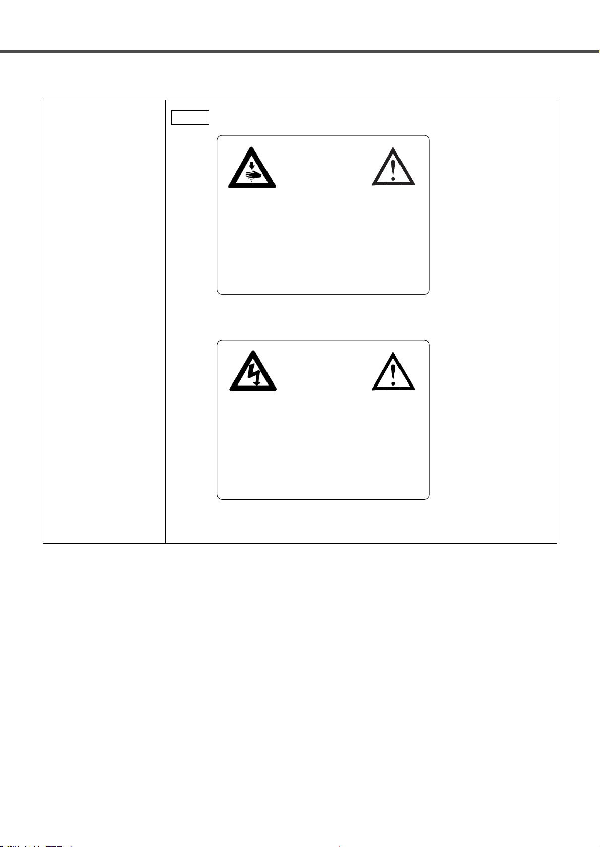
Caution
1)
2)
1-6) Message
Caution
경고
Do not operate without finger guard and safety
devices. Before cleaning and changing thread,
bobbin, needle and etc, turn off main switch.
손가락 보호대와 안전장치 없이 작동하지 마십
시오. 실, 보빈, 바늘 교환시나 청소전에는 반드
시 주전원의 스위치를 꺼 주십시오.
Caution
경고
Hazardous voltage will cause injury. Turn off main
switch and unplug power cord before opening this
cover.
위험한 전압으로 손상을 입을 수 있습니다. 덮
개를 열기 전 메인 스위치를 끄고 파워 전원
플러그를 뽑아 주십시오.
9
22
Specifications
Classification
Application
Thread trimmer Type
Max. sewing speed
SPC/E-BH6100-00 SPC/E-BH6100-01 SPC/E-BH6100-02
Length
Formal dress Jeans, Working clothes
short thread trimmerlong thread trimmernon-thread trimmer
10~50mm
10~40mm
Needle
Lift of presser bar
X, Y drive type
Cutter drive type
Safety device
No. of patterns
No. of stitches
Memory
Motor used
Air-compressed
Optimum temperature
Optimum humidity
voltage
Lubrication
Max. 13mm
2-phase stepping pulse motor
Air Solenoid
Emergency stop function during sewing operation
Max. 99 pattern (Standard: 4 pattern)
300(stitch number)/1 pattern
EEPROM
Motor direct connection type AC servo motor (550W)
0.5Mpa(5kgf/cm
2
)
5℃ ~ 40℃
20% ~ 80%
1-phase: 100 ~ 240V , 3-phase : 200 ~ 415V, 50/60Hz
Automatic
Schmetz Do x 579 (Nm90~Nm125)
A
B
C
D
14[mm]~20[mm]
20[mm] ~ 26[mm]
26[mm] ~ 32[mm]
32[mm] ~ 40[mm]
Buttonholes
Width
Max. 2,500spm
2.1~3.4mm
(average)

10
33
Power Voltage Connection
1)
Voltage Specifications
The voltage information is displayed as below on the tag attached to the power cord.
1. Do not use if the voltage specification is different.
2. If voltage change is necessary, see "How to Change Power Voltage."
■ 1-phae connection (100V, 110V, 120V, 200V, 220V, 240V)
■ 3-phase connection (200V, 220V, 240V, 380V)
· In case of 3-phase 380V, a separate transformer box shall be installed on the table. (Please check
it out when placing an order.)
Notice
3-1) Power Voltage and Power Cord
이 기계의 전기 사양은 공장 출고 시 아래의 표기대로 결선되어 있습니다.
V
단상 (1 Phase) 삼상 (3 Phase)
110V 120V 220V 240V 220V 240V
V
V
The Electric Specification of This Machine is Connected Under Marked.
V
11
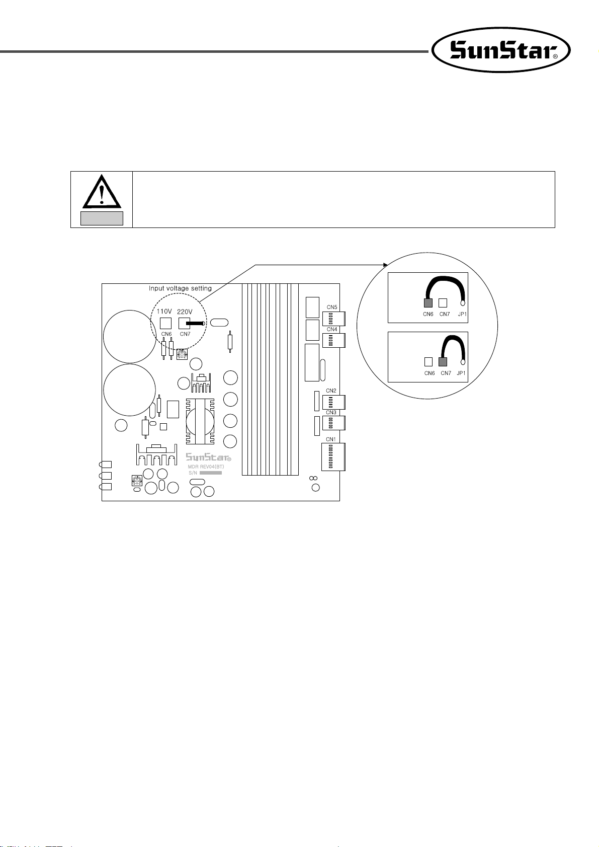
3-2) How to Change Power Voltage
■ Use SMPS to maintain constant voltage, while the input voltage is changed.
■ Since free voltage is used, according to the input voltage, the switch connector shall be used to change the voltage of the main
board between 110V and 220V.
· If the setting of the voltage switch connector is wrong, it may cause damage to the control box.
Notice
In case where
the input voltage
is 110V
In case where
the input voltage
is 220V
12
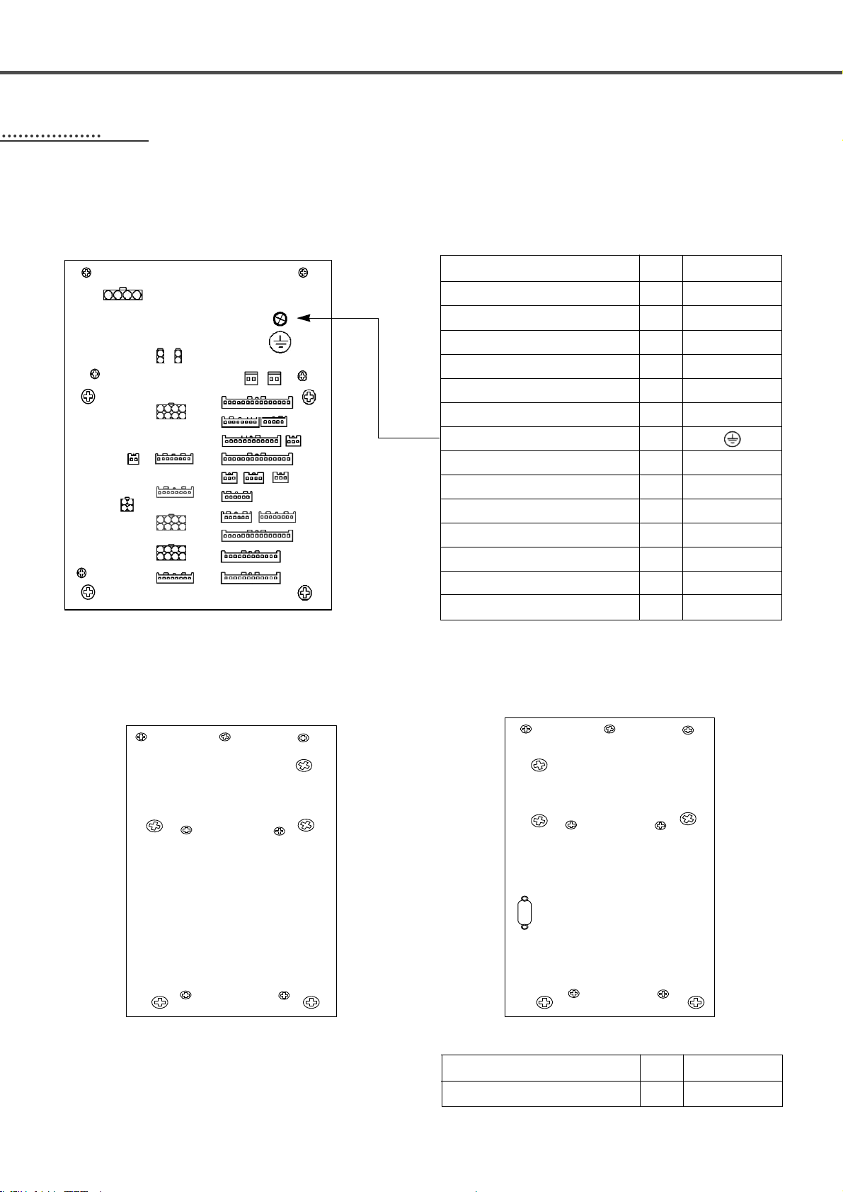
44
Cable Connection to Control Box
4-1) Internal wiring of the control box
※ Wiring Diagram of Control Box
[Rear Cover of Control Box]빣
[Left Side Cover of Control Box] [Right Side Cover of Control Box]
X(Yellow),Y(Blue),P(Red)-shaft and step motor connection
X(Yellow),Y(Blue),P(Red)-shaft and encoder mid-connection
Thread tension solenoid
AIR solenoid output 1 (White)
OP connection
Hand switch connection
Cables for BH6100 grounding
Pneumatic pressure sensor
PHOTO sensor 2 (Blade Position)
Emergency stop and head safety switch
PHOTO sensor 1 (Phase Stop)
AIR solenoid output 2 (Red)
Starting Point Sensor in the X,Y,P axis (Red)
Thread Detection Sensor
CN11, CN15, CN17
CN22, CN31, CN42
CN7
CN13
CN40
CN44
CN36
CN27
CN34
CN26
CN16
CN43
CN6
Cable Name
Machine
Control Box
Main Shaft Encoder (Sanyo) Input Cable
CN8
Cable Name
Machine
Control Box
4-2) External wiring of the control box
CN8
N46 CN45
CN9 CN7
CN13
CN44
CN11
CN32
CN6
CN22
CN31
CN15
CN17
CN42
CN43
CN38
CN16
CN40
CN33
CN39
CN14
CN36 CN29 CN27
CN34
CN26 CN25
13
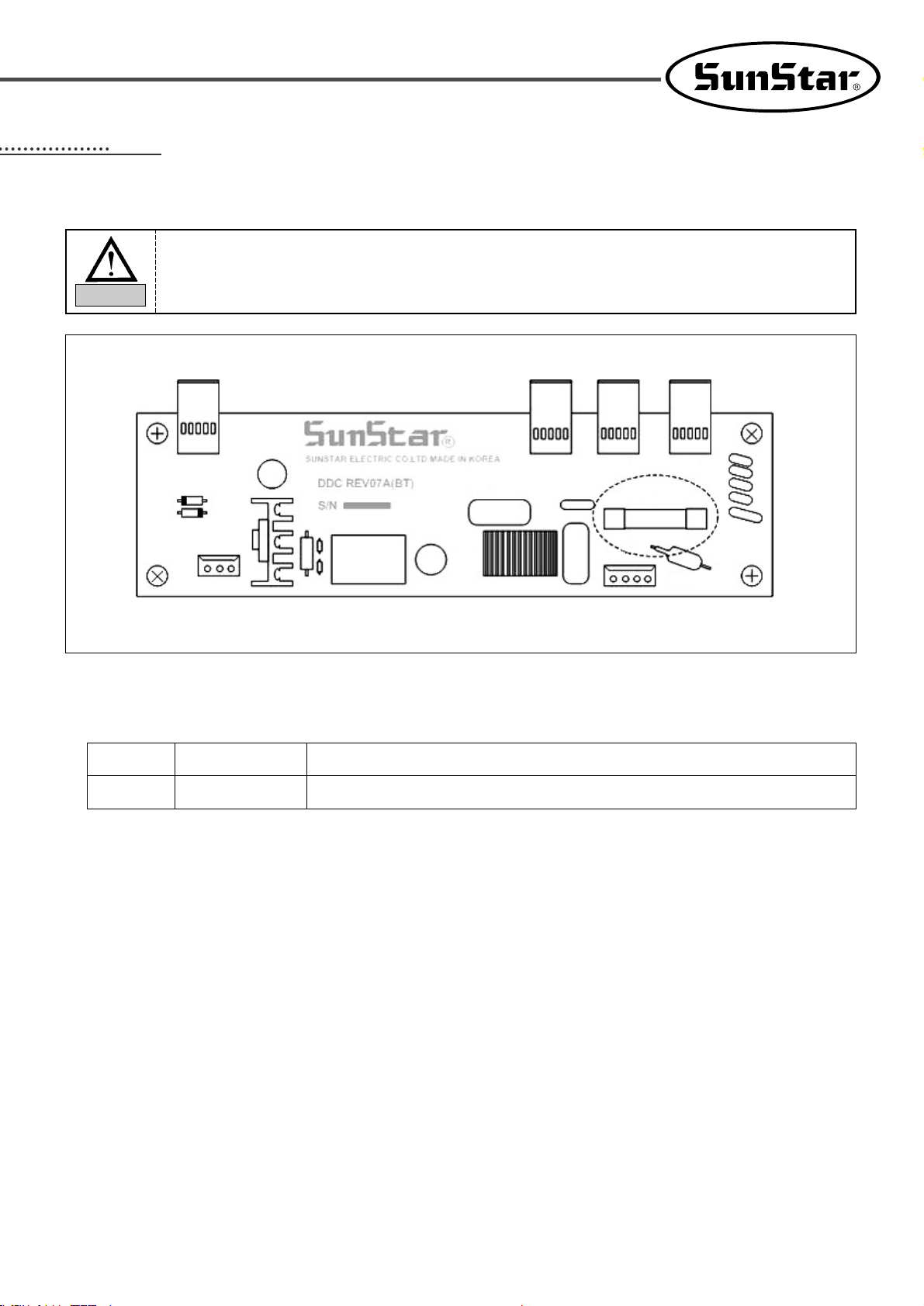
55
Fuse Exchange
No.
F1
Capacity
15A
Usage
Protect the main power
•1 fuses are used.
■Open the cover 5 minutes after turning off the power in order to prevent electric shock.
■Turn off the power and open the cover of the control box.
Then exchange the existing one with the fuse of designated capacity.
Caution
CN6
CN5
CN3 CN1 CN2
C6
L1
RV1
F1
CN4
DSA1
14
66
Use the Operational Panel and Perform Sewing
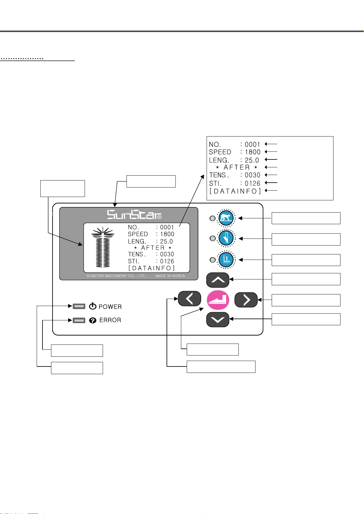
1) Operational panel
※ The change of the operational panel settings is possible only when the sewing Ready lamp is off.
6-1) Operational panel and keys
SunStar Logo
Sewing Ready Key
Knife Motion On/Off Key
Clamp Up/Down Key
Up key
Value Change (-) key
Down key
Enter key
Error Indicator
Power On/Off
Value Change (+) Key
Graphic LCD
Display
Pattern number
Stitching speed
Pattern length
Knife motion
Thread tension value
Pattern stitch
Pattern Information
15
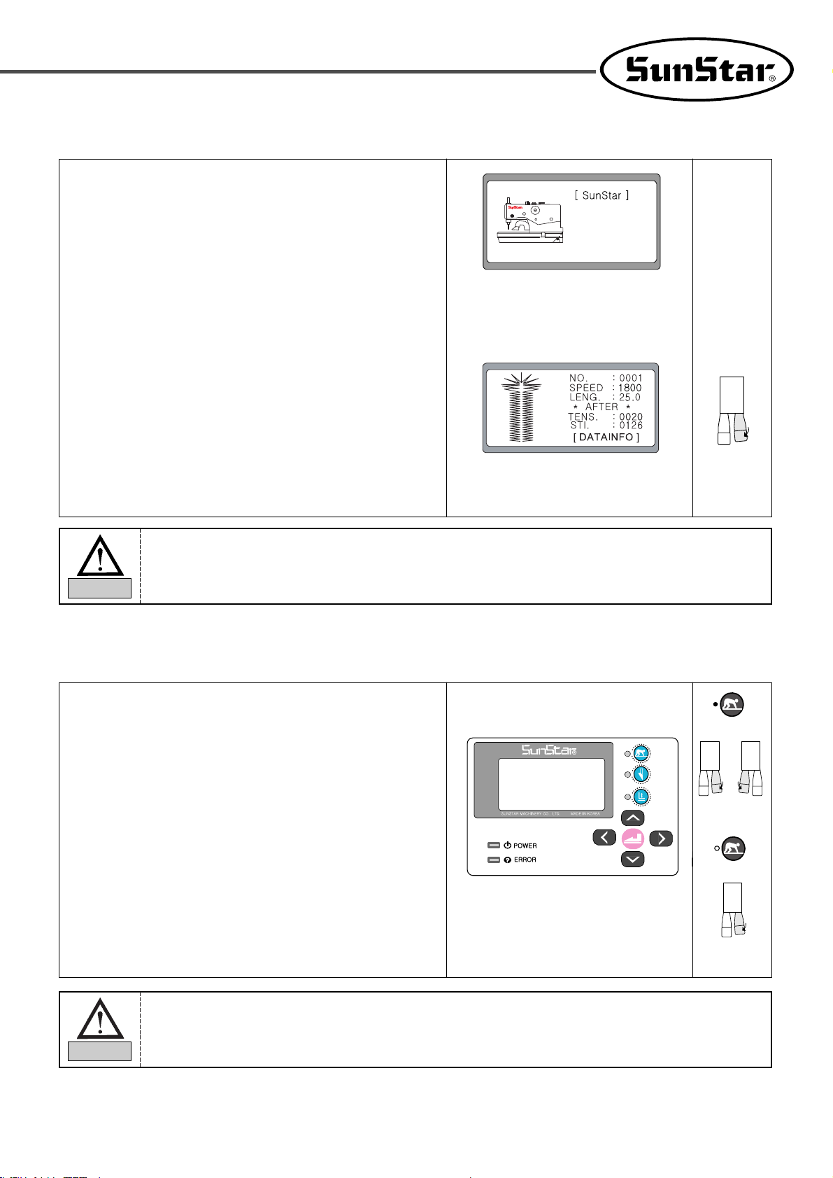
2) Initial display
■ In case of 『BH6100-01』, the following logos are displayed on
the screen when the power is turned on.
•First line : Company name
•Second line : Machine Type
•Third line : Version
■ Type name – Type 00 : non-thread trimmer → BH6100 - 00
T ype name – Type 01 : long thread trimmer → BH6100 - 01
T ype name – T ype 02 : short thread trimmer → BH6100 - 02
■ Press the right hand switch to change to the sewing mode.
3) Sewing mode
When the needle bar is not rightly positioned, an alarm is issued, and error message is shown on the
screen. Use the hand pulley to compensate the needle position, and then the error message is
automatically gone and the logo is displayed.
Caution
••
When the sewing READY lamp is on, the knife motion On/Off key is deactivated.
••
In case of changing Parameter Group A-22 to “One Switch” mode, the presser foot descent
and sewing can be simultaneously performed using the left-side hand switch.
Caution
1. When pushing the ‘Ready’ key, the lamp is lit.
2. When the right-hand side switch is pressed, the clamp descends.
The clamp up/down lamp is turned on.
3. When the left-hand side switch is pressed, the feed base moves to
the sewing ready position, and the fabric opening device opens.
When the feed base completely moves to the sewing ready
position, the sewing begins.
↓
↓
→
[Two Switch
Mode]
[One Switch
Mode]
BH6100-01
CB100124
16
When the sewing READY lamp is off, the knife on/off key is
activated. When pressed, the lamp is on or off.
•Lamp on : The knife can operate.
•Lamp off : The knife can not operate.
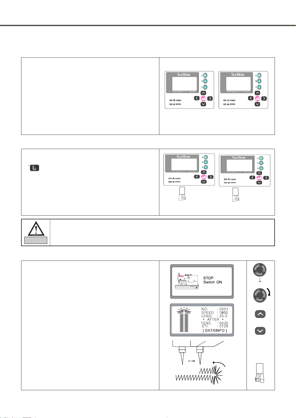
4) Knife operation
When the READY lamp is off, and either Clamp Up/Down
( ) or the right hand switch is pressed, the clamp starts
operation.
•Lamp on, right hand switch pressed: clamp down
•Lamp off, right hand switch pressed: clamp up
5) Clamp operation
6) Needle bar forward/backward adjustment after sewing suspension
[The knife can operate] [The knife can not operate]
① When the suspension switch is pressed in the middle of sewing,
sewing is stopped, and a new screen appears.
② If the suspension switch is turned counter-clockwise and
returned to the original position, the screen goes back to the
initial sewing screen.
③ Press “Up” or “Down” key to make the needle bar move
forward or backward. Likewise, the needle bar could be
relocated to a desired position by using the Up or Down key.
④ When the start button is pressed, sewing resumes from the newly
set needle bar position.
OR
↓
Back Stitch
Sewing
direction
In case of changing to “One Switch”mode, there is no the presser foot lowering or raising motion
because lowering and sewing is operating with the left hand switch at the same time.
Caution
(Clamp down) (Clamp up)
17
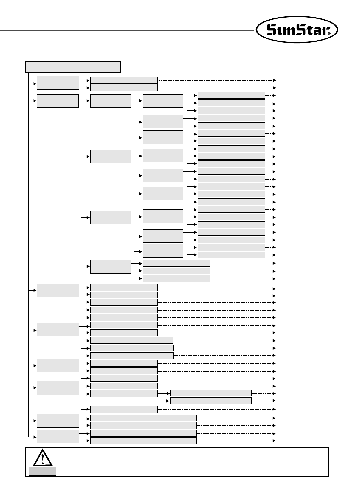
7) Menu overview
DATAINFO (Menu)
1. Speed
(Set the Speed)
1. Main(Main Speed)
[Scope of parameter values]
1000[rpm]~2200[rpm]
2. Up Bar(Eyelet Speed)
1. Taper
(Taper Pattern)
1. Up Bar (Eyelet
Compensation)
1. Stitch (Stitch No. Setting)
2. Length (Up/Down Knife Space)
3. Slant (Slant Compensation)
1000[rpm]~2200[rpm]
4[stitches]~20[stitches]
-1.0[mm]~1.0[mm]
1~5
0.2[mm]~2.0[mm]
5[mm]~38[mm]
0.3[mm]~2.0[mm]
0.0[mm]~20.0[mm]
2. Zigzag (Straight Line
Compensation)
3. Dn Bar (Taper
Compensation)
1. Pitch (Pitch Setting)
2. Length (Pattern Length Setting)
1. Offset (Taper Start Position)
2. Length (Length Setting)
2. Tack
(Tack Pattern)
1. Up Bar (Eyelet
Compensation)
4. Eyelet (Eyelet
Shape Pattern)
1. InSide (Inside)
2. OutSide (Outside Compensation)
3. Stitch (Stitch No. Setting)
1. Stitch (Stitch No. Setting)
2. Length(Up/Dn knife space)
3. Slant (Slant Compensation)
4[stitches]~20[stitches]
-1.0[mm]~1.0[mm]
1~5
0.2[mm]~2.0[mm]
5[mm]~38[mm]
5[stitches]~18[stitches]
2.0[mm]~6.0[mm]
0.0[mm]~2.0[mm]
2.0[mm]~5.0[mm]
-1.0[mm]~1.0[mm]
16[stitches]~60[stitches]
2. Zigzag (Straight Line
Compensation)
3. Dn Bar (Tack
Compensation)
1. Pitch (Pitch Setting)
2. Length (Pattern Length Setting)
1. Stitch (Stitch No. Compensation)
2. Length (Stitch Length Compensation)
3. Overlap (Overlap Setting)
3. Knife(Knife-Related
Settings)
1. Length(Knife No)
1~6
2. L Space(Left Space)
4. KNF POS(Place Motion Space)
5. CP Type (sewing size setting)
-0.5[mm]~0.5[mm]
5[pulse]~20[pulse]
( *)
4. E_Comp.(Compensate
the Up bartack part)
1. Rotate(Eyelet Rotation)
-6~6
2. Radius(Eyelet Radius)
3. X_Comp(X Position Compensation)
-3~5
-6~6
5. C_Comp.(Compensate
the Zigzag part)
1. Rotate(Straight Line Rotation)
-6~6
2. Length(Straight Line Pitch)
3. Width(Straight Line Width)
-1~6
-1.0[mm]~1.0[mm]
6. T_Comp.(Compensate
the Slant)
1. Taper (Taper Pattern Compensation)
-5~5
2. Tack (Tack Pattern Compensation)
-1.0[mm]~1.0[mm]
-1.0[mm]~0.0[mm]
7. Chain(Set the Chain
Sewing)
On / Off
1[unit]~15[unit]
8. BT_STI(Set the
Back-Tack)
0[stitches]~2[stitches]
0[stitches]~2[stitches]
2. Pattern
(Set the Pattern)
3. R Space(Right Space)
-0.5[mm]~0.5[mm]
4. R_Comp(Adjustment of right side slant width)
-1.0[mm]~1.0[mm]
5. L_Comp(Adjustment of left side slant width)
-1.0[mm]~1.0[mm]
3. Radial (Radiation pattern reply correct)
-6~6
3. Radial
(Radiation pattern)
1. Up Bar (Eyelet
Compensation)
1. Stitch (Stitch No. Setting)
2. Length(Up/Dn knife space)
3. Slant (Slant Compensation)
4[stitches]~20[stitches]
-1.0[mm]~1.0[mm]
1~5
0.2[mm]~2.0[mm]
5[mm]~38[mm]
5[stitches]~20[stitches]
0
2. Zigzag (Straight Line
Compensation)
3. Dn Bar (Tack
Compensation)
1. Pitch (Pitch Setting)
2. Length (Pattern Length Setting)
1. Stitch (Stitch No. Compensation)
2. Length ( Radiation pattern long)
1. OnOff(Enable/Disable the Chain Sewing Function)
2. Set_No(Set the Chain Sewing)
1. Start(Set the Number of the Start Back-Tack Stitches)
2. End(Set the Number of the End Back-Tack Stitches)
1. X_Comp (X-direction Compensation)
2. Y_Comp(Y-direction Compensation)
1) The symbol ( *) is used to determine the clamp type (sewing size) for BH6100-02.
2) There are four clamp type options from A to D.
3) For more information on how to set the clamp type, see “6-4) Knife-related Parameter Setting”.
Caution
18
A button hole is largely composed of the up bartack part(head), the down bartack part(tail) and the zigzag (body).
※ Structure of a Pattern
8) A button hole structure
No. of eyelet stitches
Compensate
the Y knife
space
Compensate
the width
Compensate
the right
X knife
space
Compensate
the left X
knife space
Offset
Compensate
the slant
Up Bartack part
Button length
Down bartack
length
Zigzag part
Down Bartack part
1) When shipped out from the factory, the up bartack part is set at eyelet shape pattern, while the down
bartack part is set at N/A.
2) In order to use “*1 Eyelet”, the parameter group A-16 should be changed to “1”.
3) Install the eyelet-dedicated needle plate, clamp, cutter and hammer before sewing the eyelet pattern.
Otherwise, it might cause damage to the sewing machine.
Caution
Pattern
1.Up bartack
(Up Bar)
1. Radial
2.Zigzag
(zigzag)
2. Eyelet
*
1
3.Down bartack
(Dn Bar)
4. Up bartack
(Up Bar)
1. N/A
2. Taper
3. Tack
Eyelet
4. Radiation shape
19
9) Change the pattern number
① When the READY lamp is off, and the DOWN key is pressed,
NO. on the LCD is flickering.
② Use ◀(+) or ▶(-) keys to choose the desired pattern number.
(ex: Pattern No. 5)
③ Confirm the selection by pressing ENTER and the chosen
pattern is automatically generated.
↓
↓
OR
↓
When the DOWN key is pressed, the blinking section moves down on the LCD and vice versa. When
ENTER is pressed, the blinking section disappears from the screen and the chosen value is stored.
Caution
① When the sewing ready lamp is off, press the Down key five
times and the prompt blinks at ‘0030’section on the screen.
② Use ◀(+) or ▶(-) keys to select a desired thread tension number.
(ex : TENS. : 35)
③ Confirm the selection by pressing ENTER and the chosen pattern
is automatically generated.
↓
↓
OR
↓
10) Adjusting the thread tension
20
11) Function Keys
Classification
WRITER
Function Keys Description
[DATAINFO] When this key is pressed within the routine, patterns are immediately created, and
the initial screen appears.
HOME(ESC)
[DATAINFO] When this key is pressed within the routine, the changed parameter values are not
saved, and the initial screen appears.
RETURN
[DATAINFO] When this key is pressed within the routine, the screen returns to the previous
stage.
•Function keys are used within the [DATAINFO] routine.
•Press READY at the basic pattern routine to generate basic patterns. Then the display returns to
the initial screen.
•When creating patterns composed of multiple patterns, press READY at the parameter routine by
sector. If only one parameter is changed and READY is pressed, the remaining parameters of the
new pattern are same as before.
Caution
① During pressing “ DOWN ” key four times in the state of
extinguished stitching preparation lamp, the screen flicker at the
“AFTER.”
AFTER : A rear knife motion
BEFORE : A front knife motion
② Set the knife motion mode you want by using ◀(+) and ▶(-)
keys then press an ENTER key.
(ex. : BEFORE)
③ If you press the ENTER key, knife motion mode will be set.
↓
↓
OR
↓
12) A front / rear knife motion
21
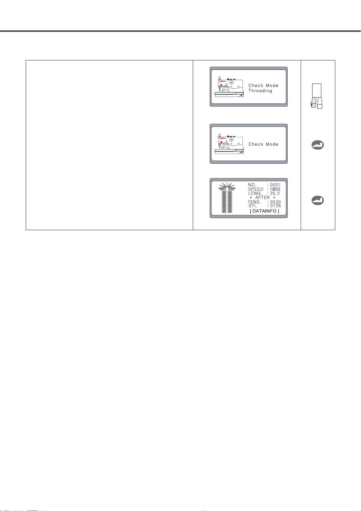
13) Threading Mode
14) Check Mode
① After turn the power on, convert into stitching mode by pressing
the right hand switch.
② If you press the right key(value change(-)) of the operation panel
for separating left/right cover panel of the feeding base at the
stitching mode, the screen is changed into the ‘Check Mode’ and
the feeding base is moving forward about 55mm.
① After turn the power on, convert into stitching mode by pressing
the right hand switch.
② The rocking motor is rotated by 180° in the counterclockwise
direction when pressing the left hand switch at the stitching
mode.
The screen is changed and the sign of ‘Threading’ is blinking.
③ The rocking motor is stopped after rotating by 180° in the
clockwise direction when pressing the ENTER key.
The screen is changed into the stitching mode.
R
Advance
22
③ The rocking motor is also rotated by 180 ° in the counterclockwise
direction when pressing the left hand switch at the check mode.
Then it changed into the threading mode.
The sign of ‘Threading’ is blinking on the screen.
④ The rocking motor is stopped after rotating by 180° in the
clockwise direction when pressing the ENTER key and the sign
of ‘Check Mode’ is displayed on the screen.
⑤ When you press the ENTER key again, the feeding base is
moving toward the initial condition and the screen is changed
into the stitching mode.
23
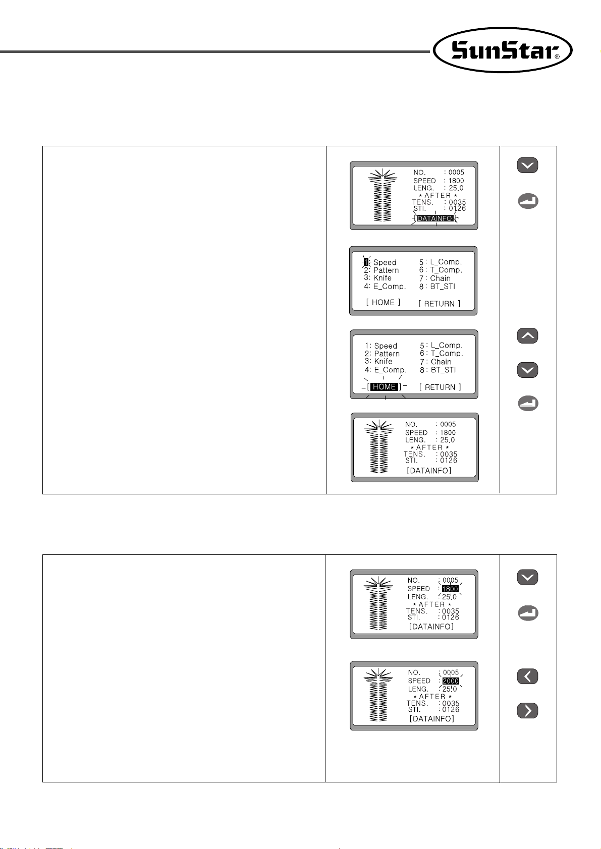
1) Change the pattern data information and the initial screen
6-2) Change the pattern data information
① Select DATAINFO by pressing the DOWN key six times, while
the READY lamp is off.
② Press ENTER and it moves to the initial screen for changing
parameter information.
◀Note▶
When the screen is shifted, No. 1 flickers.
③ Press the UP, DOWN keys, and choose [HOME] or [RETURN]
to return to the initial display.
◀Note▶
When the knife on/off key is pressed, the initial screen
appears.
④ Press ENTER and it moves back to the initial display.
2) Change the speed
① Check that the READY lamp is off, and press the DOWN key
to select SPEED.
② Set the desired speed by using ◀(+) and ▶(-).
(ex : 2000rpm)
③ Press ENTER to store the chosen value.
a. Change the speed on the initial display
↓
↓
OR
↓
↓
↓
OR
 Loading...