

SunStar SF 7400 Series, SF 7500 Series User Manual
SSUUNNSSTTAARR MMAACCHHIINNEERRYY CCOO..,, LLTTDD..
R
User’s
Manual
SF 7400 Series
SF 7500 Series
High-speed Flat Bed
Interlock Sewing
Machine
1) For proper use of the machine,
thoroughly read this manual before use.
2) Keep this manual in a safe place for
future reference in case the machine
breaks down.
MMMMEE--005511111100

Best Quality
Best Price
Best Service
SSUUNNSSTTAARR MMAACCHHIINNEERRYY CCOO..,, LLTTDD..
R
1.
Thank you for purchasing our product. Based on the rich expertise and
experience accumulated in industrial sewing machine production, SUNSTAR
will manufacture industrial sewing machines, which deliver more diverse
functions, high performance, powerful operation, enhanced durability, and
more sophisticated design to meet a number of user’s needs.
2. Please read this user’s manual thoroughly before using the machine. Make
sure to properly use the machine to enjoy its full performance.
3. The specifications of the machine are subject to change, aimed to enhance
product performance, without prior notice.
4.
This product is designed, manufactured, and sold as an industrial sewing
machine. It should not be used for other than industrial purpose.
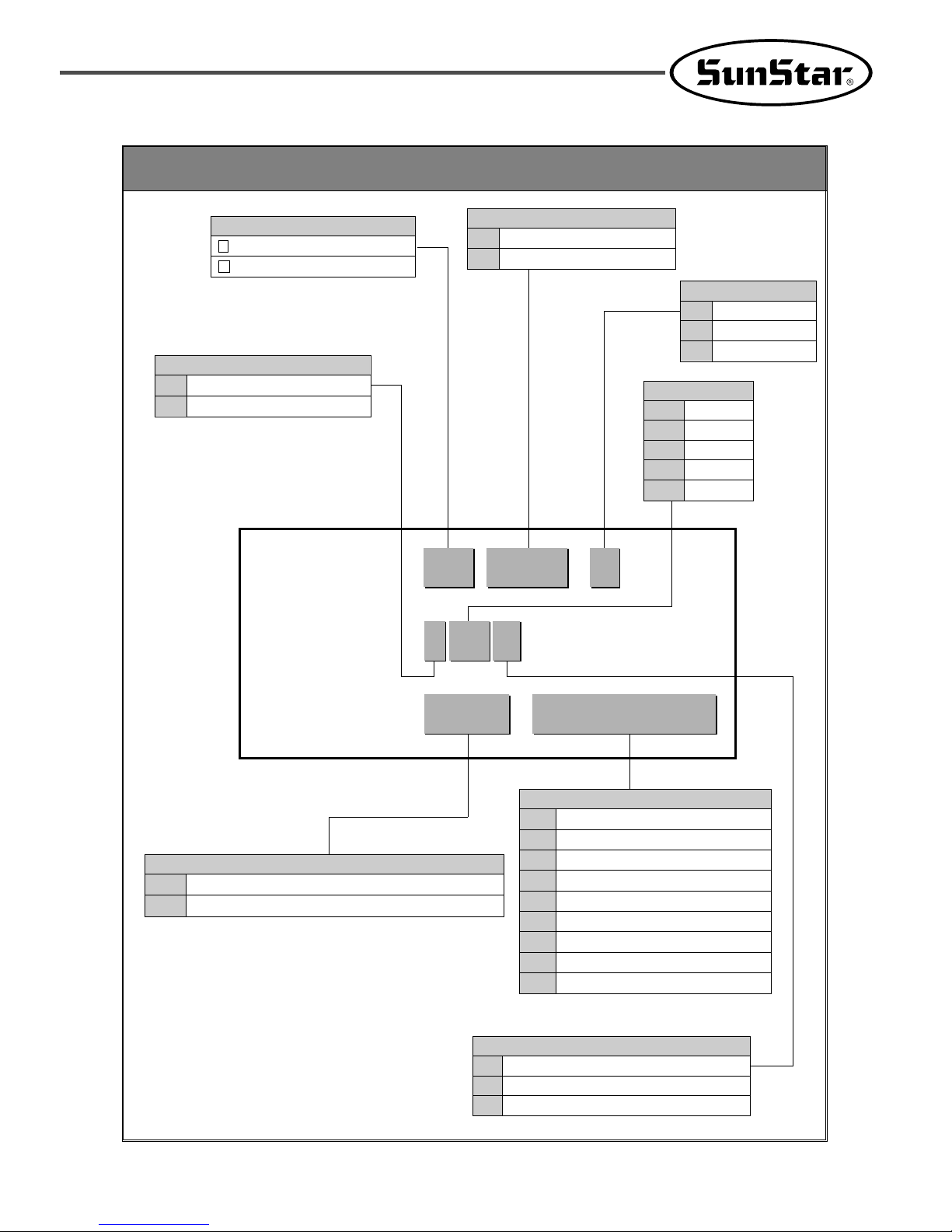
Classification of Pattern Types
MODEL SF 7500 /C
SPEC. 1 56 G
DEVICE UT-A /
/
...
SUNSTAR
F lat Bed Chain Stitch M/C
Symbol of Series
7574Flat Bed-3Needle
Flat Bed-2Needle
Bed Type & No. of Needle
C
N
M
Fortuna Ⅳ
Fortuna Ⅲ
Clutch Motor
Main Motor
01Without Top Cover Thread
With Top Cover Thread
Top Cover Thread
G
L
S
Standard
For long stitch (longer than 2.5mm)
For short stitch (shorter than 1.8mm)
Shape of Stitch Plate
32
40
48
56
64
Needle Distance
3.2mm
4.0mm
4.8mm
5.6mm
6.4mm
UT-A
UT-B
Under Thread Trimmer [2-Solenoid Valve Type]
Under Thread Trimmer [3-Solenoid Valve Type]
Device
ST-F
CO
HE
WF
ATF
TL
SL
TC
BN
Top Cover Thread Trimmer(Flat Bed)
Covering Guide
Hemming Guide
Walking Foot
Auto Tape Feeder
See Through Light for Hemming
Compact Spot light
Needle Thread Clamp
Binder
Attachment (Option)

4
CONTENTS
1. Machine Safety Regulations ................................................................6
1) Transporting machine.............................................................................................................6
2) Installing machine ..................................................................................................................6
3) Repairing machine .................................................................................................................6
4) Operating machine .................................................................................................................7
5) Safety devices.........................................................................................................................7
6) Caution mark position............................................................................................................8
7) Contents of marks ..................................................................................................................8
2. Names of machine parts ......................................................................9
3. Specifications .....................................................................................10
4. Installation ..........................................................................................11
1) Installation of table...............................................................................................................11
2) Installation of motor and belt ..............................................................................................13
3) Adjustment of belt tension ..................................................................................................13
4) Attachment of Belt Cover....................................................................................................13
5) Installing cover for needle bar thread guide........................................................................14
6) Installation of thread guide plate .........................................................................................14
5. Sewing speed and rotating direction of pulley .................................14
6. Lubrication ..........................................................................................15
1) Lubricating oil ......................................................................................................................15
2) Supplying oil ........................................................................................................................15
3) Oil Gauge and Oil Window.................................................................................................15
4) Oil change.............................................................................................................................16
5) Cleaning the oil filter ..........................................................................................................16
7. Standard adjustments of the sewing machine .................................17
1) Needle used ..........................................................................................................................17
2) Installation of needle............................................................................................................17
3) Threading..............................................................................................................................18

5
4) Adjustment of thread tension...............................................................................................18
5) Adjustment of presser foot tension......................................................................................19
6) Adjustment of presser foot...................................................................................................19
7) Adjustment of main feed .....................................................................................................19
8) Adjustment of differential feed............................................................................................21
9) Needle Cooling Device and Oil Supply Device for Needle Thread .................................22
8. Adjustment of Sewing Machine .........................................................23
1) Adjustment of Needle Thread Tension ..............................................................................23
2) Adjustment of Top Cover Thread Tension..........................................................................24
3) Adjustment of the Looper Thread Tension .........................................................................24
4) Position of Looper Cam.......................................................................................................25
5) Removing Presser Foot and Amount of Presser Foot Lift .................................................25
6) Relation between Needle and Needle Plate ........................................................................26
7) Fixing Angle and Height of Looper ....................................................................................26
8) Movement of Looper to the Right.......................................................................................26
9) How to Use Timing Gauge..................................................................................................27
10) Height of Needle Bar .........................................................................................................27
11) Longitudinal Position of Needle and Looper....................................................................27
12) Needle and Needle Guard(Rear) .......................................................................................28
13) Needle and Needle Guard(Front) ......................................................................................29
14) Height of Feed Dogs ..........................................................................................................29
15) Adjustment of needle and spreader ...................................................................................29
9. Automatic Thread Trimmer...............................................................31
1) Operation ..............................................................................................................................31
2) Wiring...................................................................................................................................33
3) Air pressure wiring map .....................................................................................................37
4) Installation of synchronizer sensor......................................................................................40
5) Adjustment of automatic thread trimmer ............................................................................41
6) Adjustment of thread tension release mechanism ..............................................................46
7) Adjustment of air wiper ......................................................................................................49
8) Presser foot lifter mechanism .............................................................................................50
6
11
Machine Safety Regulations
Safety instructions on this manual are defined as Danger, Warning and Caution.
If you do not follow the instructoins, physical injuries and machine damages might be occurred.
: This indication should be observed definitely. If not, there will be a danger during the installation, conveyance and
maintenance of the machine.
: When you follow this indication, injuries from the machine can be prevented.
: When you follow this indication, error on the machine can be prevented.
Caution
Warning
Danger
1) Transporting
machine
Danger
2) Installing
machine
Warning
3) Repairing
machine
Caution
Those in charge of transporting the machine should have a full understanding of the machine.
The following indications should be followed when the machine is being transported.
ⓐ More than 2 people must transport the machine.
ⓑ To prevent accidents from occurring during transportation, wipe off the oil on the
machine compeletely.
When the machine needs to be repaired, only the assigned troubleshooting engineer educated
at the company should take charge.
ⓐ Before cleaning or repairing the machine, turn off the main power and wait 4 minutes till
the machine is completely out of power.
ⓑ Not any of the machine specifications or parts should be changed without consulting the
company. Such changes may make the operation dangerous.
ⓒ Spare parts produced by the company should only be used for replacements.
ⓓ Put all the safety covers back on the machine after the machine has been repaired.
The machine may not work properly or breakdown, if installed in certain places, Install the
machine where the following qualifications agree.
ⓐ Remove the package and wrappings from the top. Take special notice on the nails on the
wooden boxes.
ⓑ Dust and moisture stains and rusts the machine. Install an airconditioner and clean the
machine regularly.
ⓒ Keep the machine out of the sun.
ⓓ Leave sufficient space of more than 50cm behind, and on the right and left
side of the machine for repairing.
ⓔ EXPLOSION HAZARDS
Do not operate in explosive atmospheres. To avoid explosion, do not operate this
machine in an explosive atomsphere including a place where large quantities of
aerosol spray product are being used or where oxygen is being administered unless
it has been specifically certified for such operation.
ⓕ The machine is not provided with a local lighting due to the feature of machine.
Therefore the illumination of the working area must be fulfilled by end user.
7
SF 7500 Series is made to sew patterns on fabrics and other similar materials for industrial use.
Follow the following indications when operating the machine.
ⓐ Read through this manual carefully and completely before operating the machine.
ⓑ Wear proper clothes for work.
ⓒ When the machine is in operation, do not bring your hands or body near the moving parts
of the machine, such as needle, looper, spreader, thread take-up lever and pulley, etc.
ⓓ Keep the covers and safety plates on the machine during operation.
ⓔ Be sure to connect the earthing conductor.
ⓕ Turn off the main power and check if the switch is turned “off”before opening electric
boxes such as the control box.
ⓖ Stop the machine before threading the needle or checking after work.
ⓗ Do not step on the pedal when turning the power on.
ⓘ Do not operate the machine with any cooling fan blocked.
The air-filter on control box must be cleaned once a week.
ⓙ If possible, install the machine away from source of strong electrical noise such as high
frequency welding machines
4) Operating
machine
Warning
Caution
[ Warning ]
Keep cover in place before operating, turn off power before inspecting or adjusting in order
to prevent physical injury from belt.
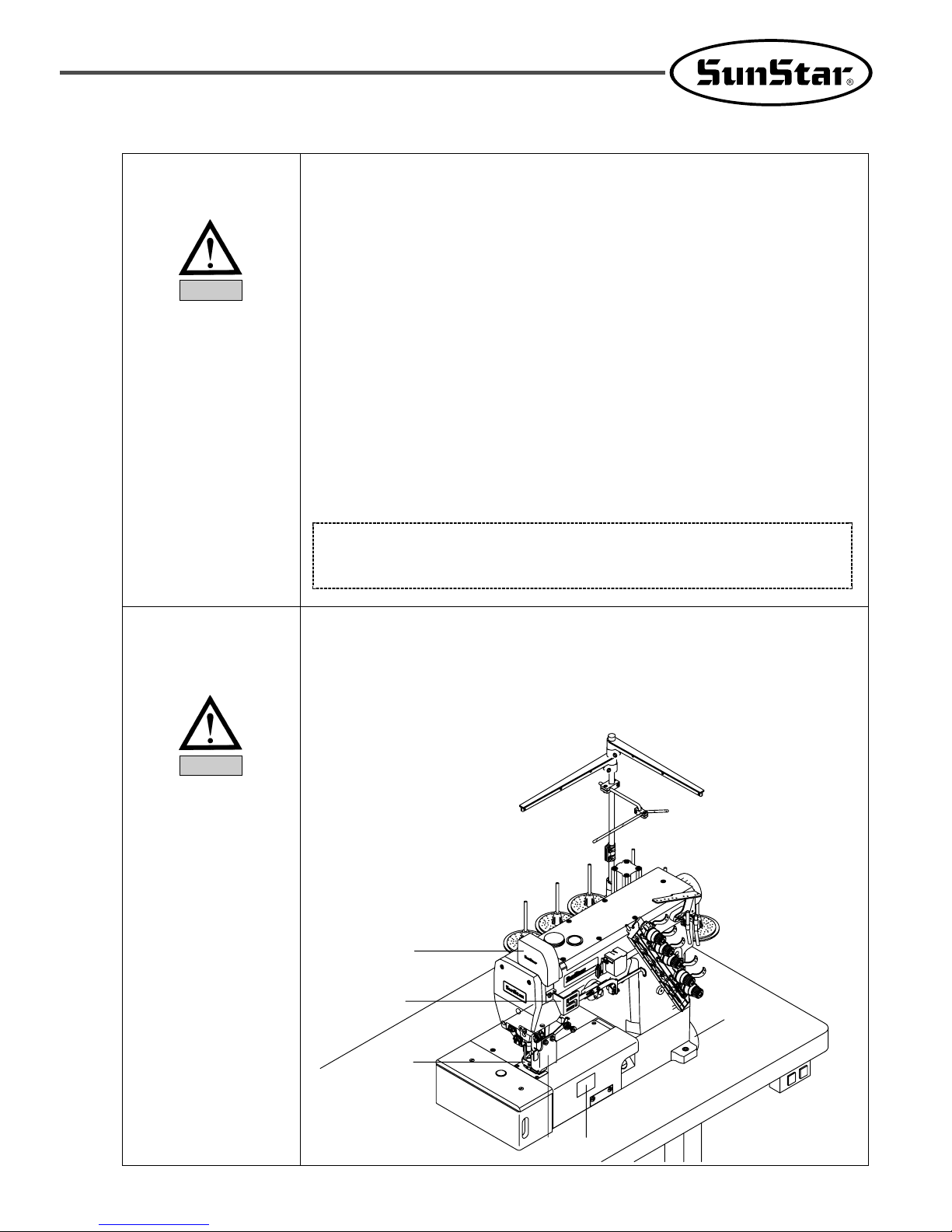
5) Safety devices
ⓐ Safety label : Cautions during machine operation
ⓑ, ⓒ Thread take-up lever cover : A device designed to prevent any physical contact with
thread take-up lever
ⓓ Belt cover: A device designed to prevent the body and clothes from getting jammed by
the moto
ⓔ Finger guard : A device to prevent contact between fingers and needles
ⓕ Safety plate: Eye-protecting device
ⓔ
ⓒ
ⓑ
ⓕ
ⓐ
ⓓ
8
Caution
(1)
(2)
7) Contents of
marks
Caution mark is attached on the machine for safety.
When you operate the machine, follow the directions on the mark.
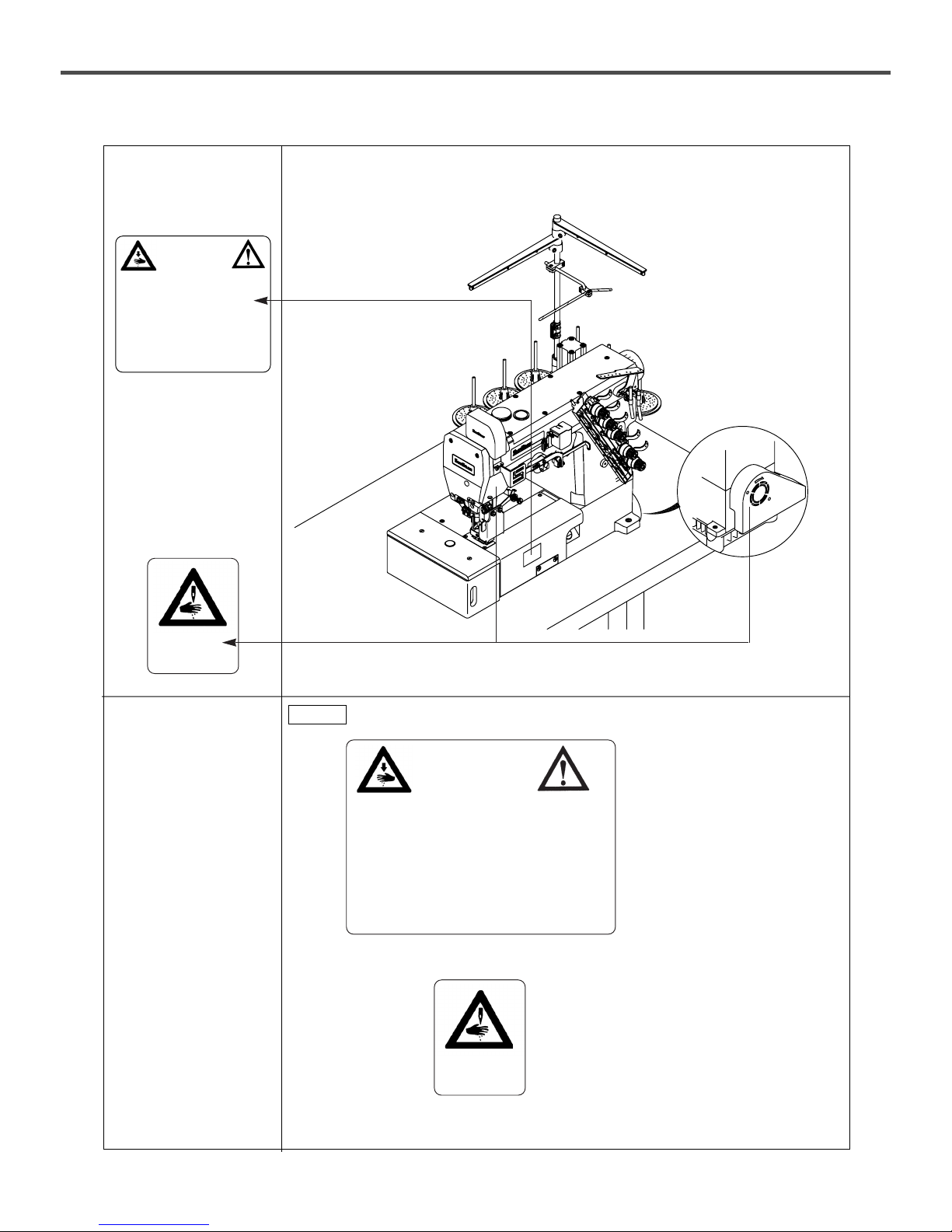
6) Caution mark
position
CAUTION
주의
Do not operate without finger guard and
safety devices. Before threading, changing
and needle, cleaning etc. switch off
main switch.
손가락 보호대와 안전장치 없이 작동하지
마십시오.
실, 바늘교환시나 청소전에는 반드시 주전원의
스위치를 꺼 주십시오.
CAUTION
주의
Do not operate without finger guard
and safety devices. Before threading,
changing and needle, cleaning
etc. switch off main switch.
손가락 보호대와 안전장치 없이 작동하지 마
십시오.
실, 바늘교환시나 청소전에는 반드시
주전원의 스위치를 꺼 주십시오.
CAUTION
경고
CAUTION
경고
[ Figure 1 ]
9
22
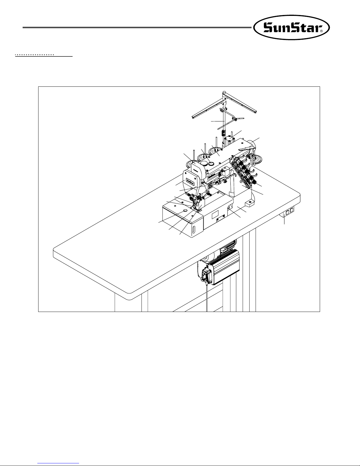
Names of machine parts
① Arm
② Bed
③ Face plate
④ Upper cap
⑤ Oil window
⑥ Knee-lifting cylinder
⑦ Upper shaft pulley
⑧ Thread-adjusting device
⑨ Oil gauge
⑩ Presser foot
⑪ Main feed regulating button
⑫ Air wiper
⑬ Power switch
⑭ Bobbin stand
Safety devices
⑮ Thread guide cover for needle thread
⒃ Thread take-up lever cover for needle thread
⒔ Finger guard
⒕ Safety plate
[ Figure 2 ]
⒔
⑪
③
⑫
②
⑬
⑭
⑮
⒃
④
⑥
⑤
⒕
⑦
⑧
⑨
①
⑩

10
33
Specifications
Description
Stitch Type
For use
Sewing speed
Stitch length
Needle
Needle clearance
Needle bar stroke
Lifting of presser foot
Feed Regulation
Differential ratio
Differential Feed Regulation
Lubrication
Oil used
Oil fan capacity
High-speed Flat Bed Three-Needle Interlock Sewing Machine
ISO 406,407,602,605
General seaming of knitted materials
Max. 6000 s.p.m (In the case of on-and-off operation)
1.4~3.6mm
Stitches per inch: 7~18; The number of stitches per 30mm: 8~21
UY
×
128GAS No. 65 ~ No. 90(Standard : No. 70)
2-needle: 3.2, 4.0, 4.8, 5.6, 6 mm
3-needle: 5.6, 6.4 mm
31mm
Max. 8.0 mm (7 mm if equipped with a spreader)
Push-Button type
Max. Normal Differential Ratio → 1 : 2
Max. Reverse Differential Ratio → 1: 0.7
Adjusting screw and adjusting lever
Automatic lubrication by oil pump
All-purpose machine oil
1100CC
Model SF 7500 Series
11
44
Installation
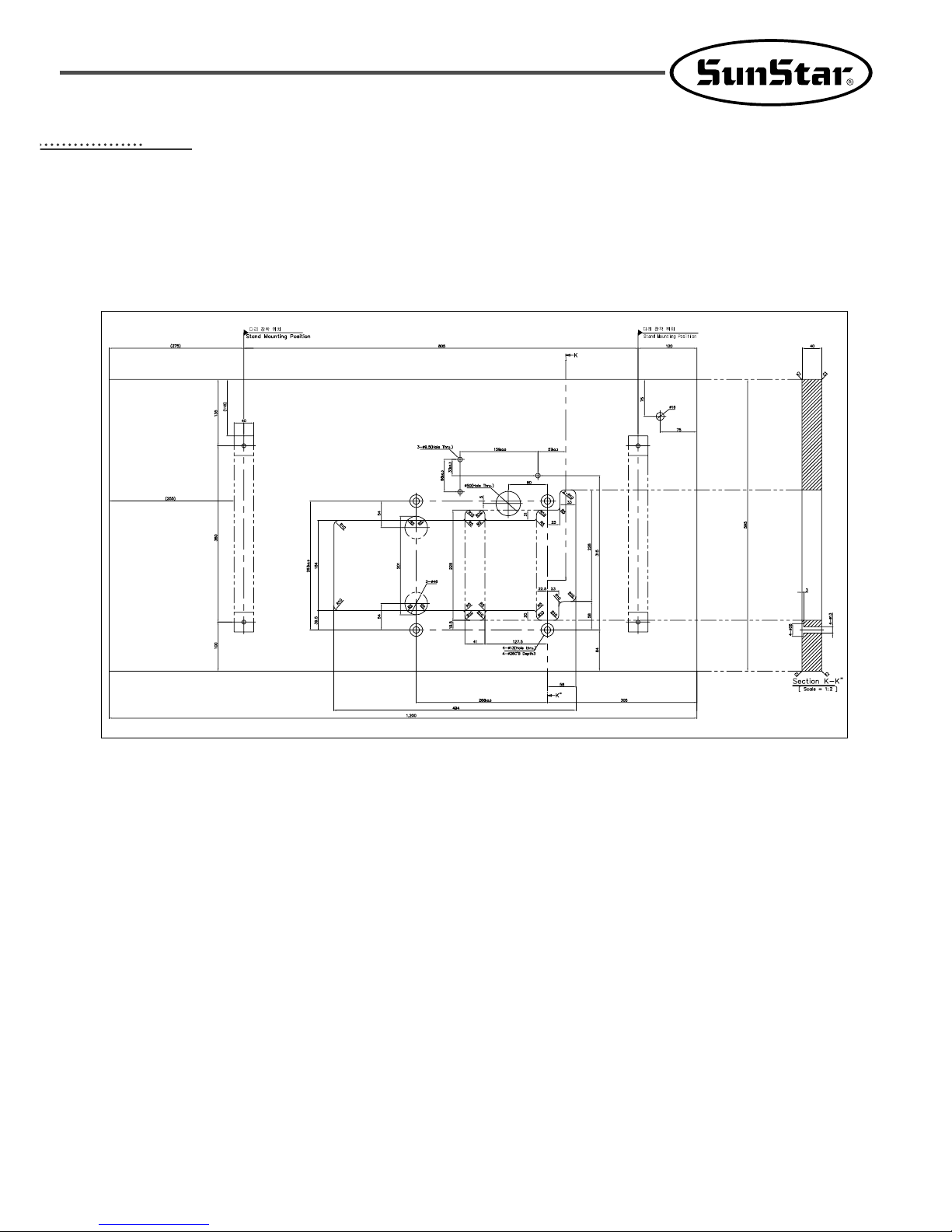
[ Figure 3 ]
1) Installation of table
⑴ Types of table
A. Supporting Board Type
12
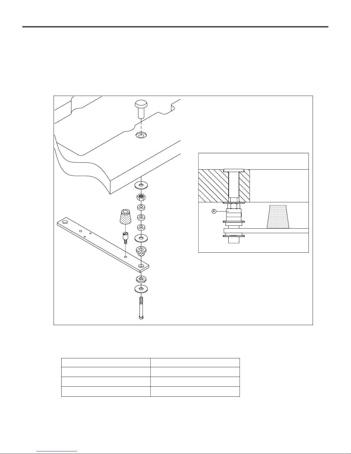
(2) Installation of Supporting Board
Install the sewing machine as shown in [Fig. 4].
Insert screws into the bed supporting board to fix the bed on the table. Place rubber cushions on top of screws for safety.
Then install the sewing machine.
※ Required Number of Spacer A
[ Figure 4 ]
Thickness of Table Number of A
40mm 3×4 = 12
45mm 2×4 = 8
50mm 1×4 = 4
SF 7500 Series
13
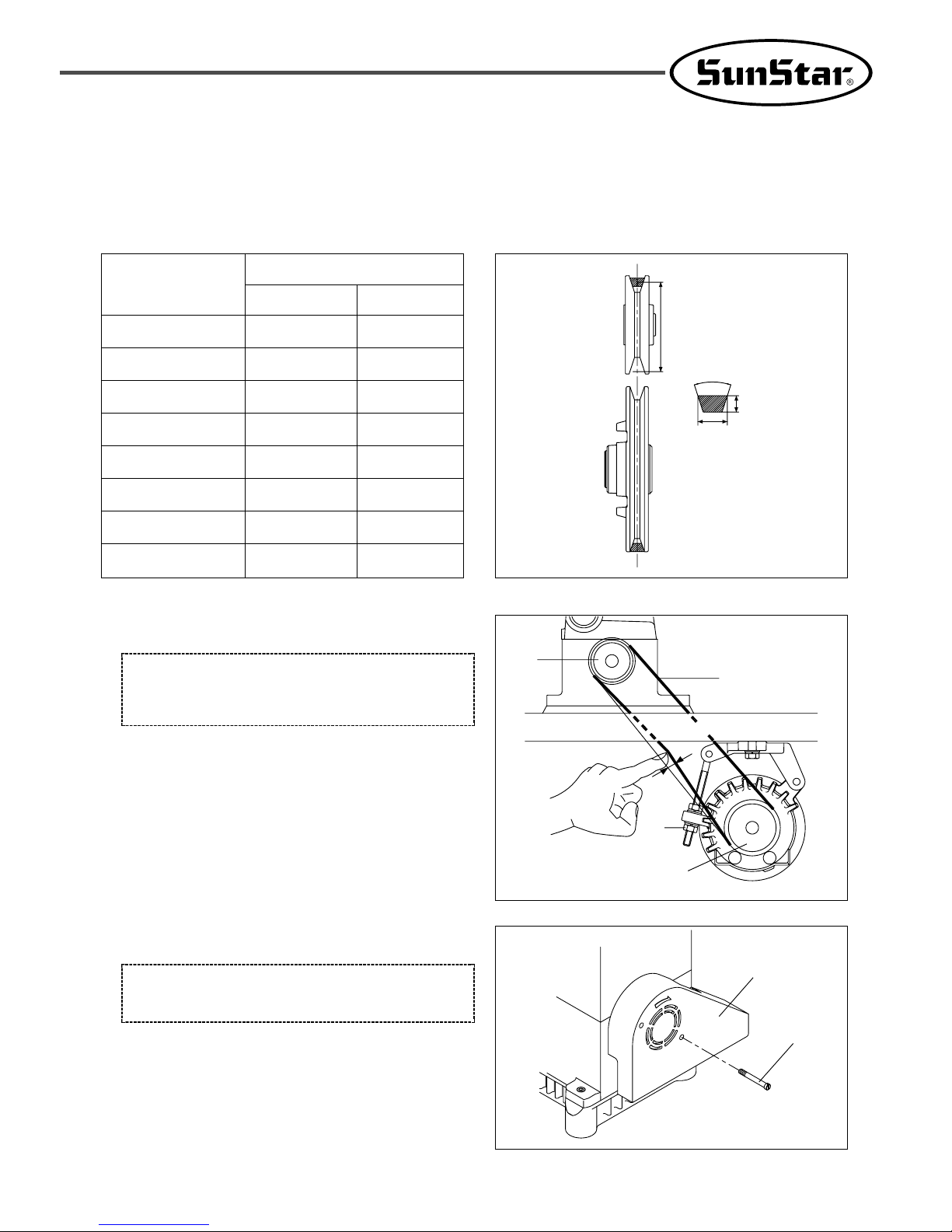
2) Installation of motor and belt
Use a 3-Phase, 2-Pole, 550W(3/4 HP) clutch motor and M-type V-belt for the machine.
Start the pedal. When the motor pulley begins to move to the left, adjust the position of the motor so that the centers of the
motor pulley and the M/C pulley meet with each other.
※ The diameter of pulleys in the market is generally set with a 5 mm clearance.
75
80
85
90
100
110
120
130
s.p.m of machine
50Hz 60Hz
3,200 3,900
3,400 4,100
3,600 4,400
3,900 4,700
4,300 5,200
4,700 5,700
5,100 6,200
5,500 6,700
[ Figure 5 ]
5.5mm
61mm
10mm
40。
Diameter. of Motor
Pulley(mm)
3) Adjustment of belt tension
[ Warning ]
Be sure to turn the power switch off before adjusting belt
tension.
Turn the screw④ of the motor③ around. Adjust the belt ①
to go in approximately 10~20mm when its center portion is
pushed with a finger. (Refer to figure 6)
[ Figure 6 ]
①
④
③
②
10~20mm
4) Attachment of Belt Cover
[ Warning ]
Always install the belt cover for safety.
Fasten the belt cover (upper)① with a screw② as shown in
figure 7.
[ Figure 7 ]
①
②
14
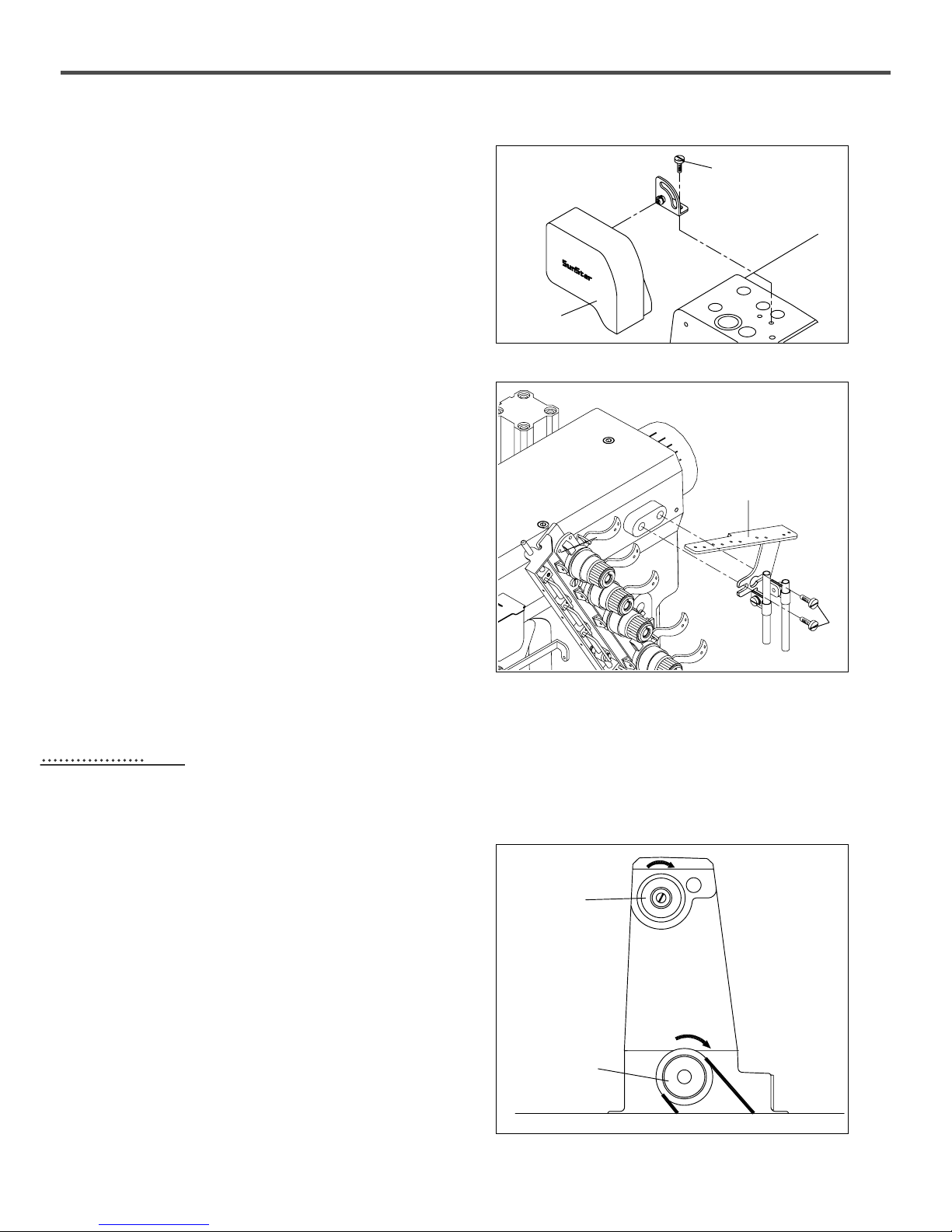
5) Installing cover for needle bar thread
guide
As illustrated in the figure, fix the cover② for needle bar
thread guide onto the arm with two screws①.
[ Figure 8 ]
①
②
6) Installation of thread guide plate
Use screws ① (2 each) to mount the thread guide plate ②
onto the arm as described below in the figure.
[ Figure 9 ]
②
②
①
The maximum speed of the sewing machine is 6,000 s.p.m,
and 4,000 s.p.m for commercial use.
To ensure durability, run the sewing machine at 4,000 s.p.m
for 200 hours of operation (or 1 month) when using the
machine for the first time.
As shown in figure 10, the rotating direction of the lower
shaft pulley① and upper shaft pulley② is clockwise.
Sewing speed and rotating direction of pulley
55
[ Figure 10 ]
①
②
15
[ Warning ]
Be sure to turn the power switch off before oiling
[ Caution ]
Do not put foreign materials into the lubricating oil. It will degrade the lubricating oil and cause mechanical breakdowns.
1) Lubricating oil
Use industrial-purpose lubricating oil supplied by SunStar or SF oil by YANASE for this particular type of sewing machine.
66
Lubrication
[ Caution ]
Too little oil may cause mechanical breakdowns and too much may degrade the quality of sewing materials. Be sure to
adjust the amount of oil appropriately.
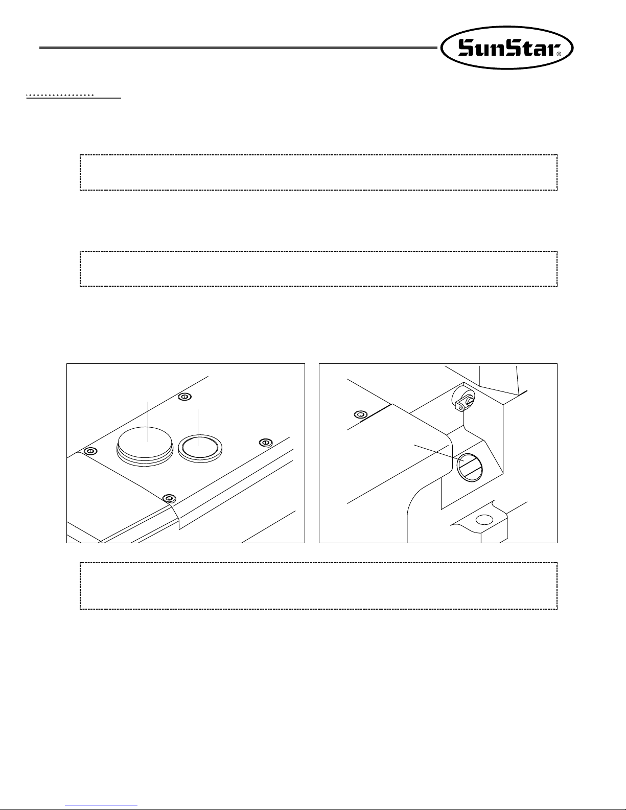
2) Supplying oil
The sewing machine is not oiled when shipped out from the factory. To ensure trouble-free use of the sewing machine, open
the upper rubber lid ① and supply oil to the upper line of the oil gauge ③.
[ Figure 12 ][ Figure 11 ]
①
②
③
3) Oil Gauge and Oil Window
Always check the oil gauge ③ before starting the machine. Supply oil if the remaining oil comes short of the lower line of
the gauge.
When operating the machine, check the flow of the oil through oil window ②.
 Loading...