

SunStar SC 8200J Series, SC 8200J/01-B/PF, SC 8200J/02-B/MF, SC 8200L/01-R/PF, SC 8200L/02-R/MF User Manual
Page 1

1) FOR AT MOST USE WITH EASINESS,
PLEASE CERTAINLY READ THIS MANUAL
BEFORE STARTING USE.
2) KEEP THIS MANUAL IN SAFE PLACE
FOR REFERENCE WHEN THE MACHINE
BREAKS DOWN.
MMMMEE--110000440077
USER
’’
S MANUAL
R
SSuunnSSttaarr CCOO..,, LLTTDD..
SC 8200J Series
Direct Drive,
Feed-off-the-Arm
3 Needle 6 Thread Double
Chain Stitch M/C
Page 2

Best Quality
Best Price
Best Service
SSUUNNSSTTAARR CCOO..,, LLTTDD..
R
1.
Thank you for purchasing our product. Based on the rich expertise and
experience accumulated in industrial sewing machine production, SUNSTAR
will manufacture industrial sewing machines, which deliver more diverse
functions, high performance, powerful operation, enhanced durability, and
more sophisticated design to meet a number of user’s needs.
2. Please read this user’s manual thoroughly before using the machine. Make
sure to properly use the machine to enjoy its full performance.
3. The specifications of the machine are subject to change, aimed to enhance
product performance, without prior notice.
4.
This product is designed, manufactured, and sold as an industrial sewing
machine. It should not be used for other than industrial purpose.
Page 3
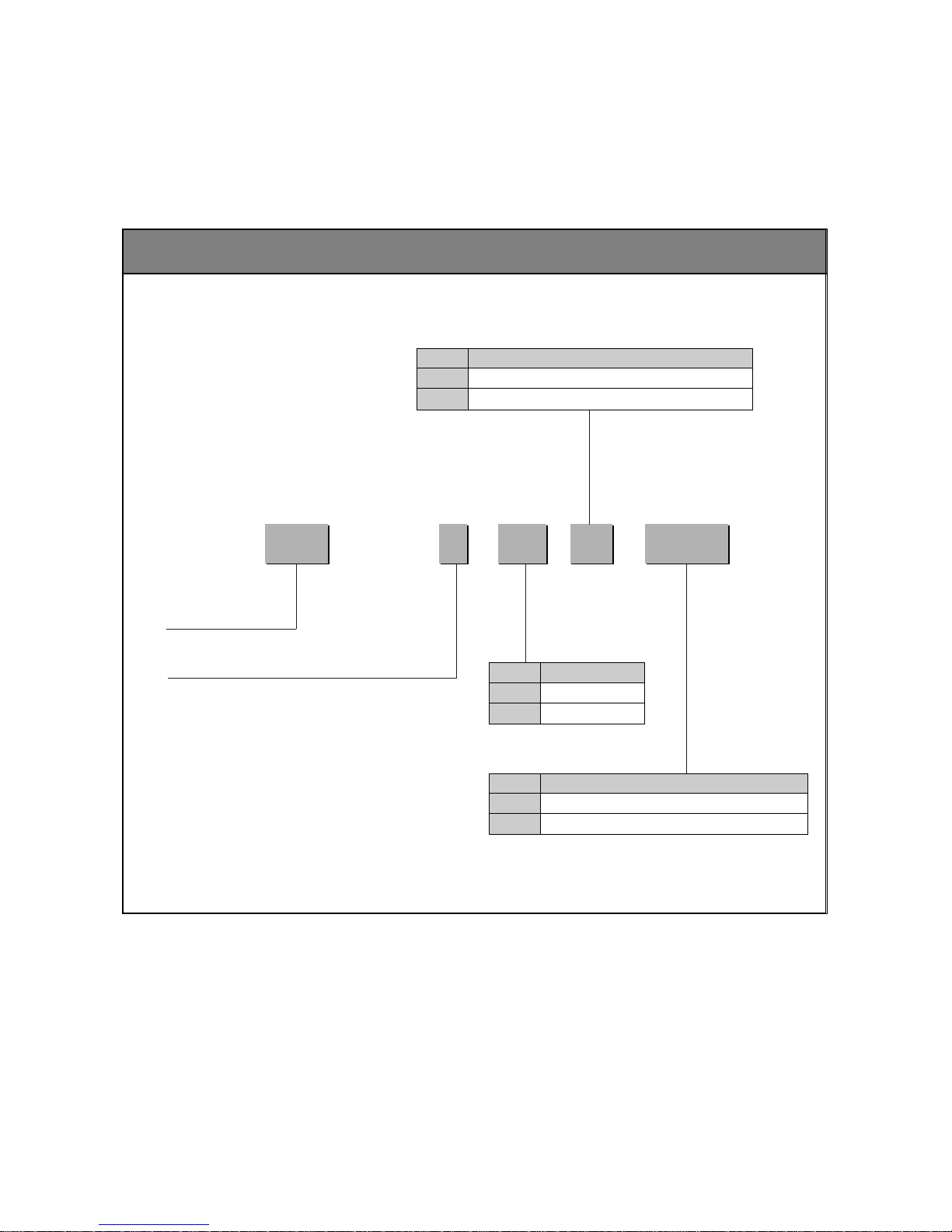
Machine Type
SC 8200 J / 01-
/
Sunstar Chain Stitch
J : Jean
L : Light Materials
01
Code
Direct Motor
02
Clutch Motor
Motor
B
R
Code
Roller Type Puller(For Heavy weight Materials)
Belt Type Puller(For Light Materials)
Puller type
PF
MF
Code
Structure of pneumatic presser foot(Direct)
Structure of Mechanism presser foot(Clutch)
Presser foot type
*Machine Type
SC 8200J/01-B/PF
SC 8200J/02-B/MF
SC 8200L/01-R/PF
SC 8200L/02-R/MF
Page 4

4
Contents
1 Machine Safety Regulations ------------------------------------------------------------------ 6
1) Transporting machine ------------------------------------------------------------------------------ 6
2) Installing machine ----------------------------------------------------------------------------------- 6
3) Repairing machine ---------------------------------------------------------------------------------- 6
4) Operating machine ---------------------------------------------------------------------------------- 7
5) Safety devices ---------------------------------------------------------------------------------------- 7
6) Caution mark position ------------------------------------------------------------------------------ 8
7) Contents of marks ----------------------------------------------------------------------------------- 8
2. Machine Parts ----------------------------------------------------------------------------------------- 9
3. Specifications
--------------------------------------------------------------------------------------- 10
4. Installation
--------------------------------------------------------------------------------------------- 11
1) Table Installation ----------------------------------------------------------------------------------- 11
2) Machine Head Installation ----------------------------------------------------------------------- 12
3) Ground Wire Connection ------------------------------------------------------------------------ 13
4) Attaching the pulley cover(clutch type) ------------------------------------------------------- 13
5) Connection to clutch-type pedal --------------------------------------------------------------- 14
6) LRP Puller Attachment --------------------------------------------------------------------------- 15
7) SRP Puller Attachment --------------------------------------------------------------------------- 17
8) Sewing of several clothes as one (FEED-OFF-ARM)
Attaching & Setting Puller to Sewing Machine---------------------------------------------- 19
5. Machine Preparation ----------------------------------------------------------------------------- 23
1) Oil Supply -------------------------------------------------------------------------------------------- 23
6. Sewing Preparation ------------------------------------------------------------------------------- 25
1) Needle Installation --------------------------------------------------------------------------------- 25
2) Lower Thread Placement ------------------------------------------------------------------------ 25
3) Upper Thread Placement ------------------------------------------------------------------------ 26
4) Handling of Waste Oil ----------------------------------------------------------------------------- 26
7. Sewing ---------------------------------------------------------------------------------------------------27
1) Sewing ------------------------------------------------------------------------------------------------ 27
Page 5

5
2) Trial Operation (pedal operation method) --------------------------------------------------- 28
3) Trial sewing (How to operate a clutch-type pedal) ---------------------------------------- 28
8. Thread T ension ------------------------------------------------------------------------------------- 29
1) Thread Tension Adjustment --------------------------------------------------------------------- 29
2) Adjustment of Presser Bar Pressure --------------------------------------------------------- 29
3) Adjusting the pneumatic presser bar --------------------------------------------------------- 30
9. Cleaning ------------------------------------------------------------------------------------------------ 31
1) Daily Cleaning -------------------------------------------------------------------------------------- 31
10. Adjustment ------------------------------------------------------------------------------------------ 32
1) Adjustment of Needle Bar Height -------------------------------------------------------------- 32
2) Adjustment of Needle and Looper Timing --------------------------------------------------- 33
3) Needle Avoiding Looper Timing --------------------------------------------------------------- 33
4) Adjustment of Needle Bar Guide -------------------------------------------------------------- 34
5) Adjustment of Feed Dog Height --------------------------------------------------------------- 34
6) Adjustment of Thread Release Lever -------------------------------------------------------- 35
7) Adjustment of Thread Take-up Guide -------------------------------------------------------- 35
8) Adjustment of Upper Thread Adjusting Cam ----------------------------------------------- 36
9) Adjustment of Thread Release Shaft --------------------------------------------------------- 36
10) Adjustment of Lower Thread Take-up Timing -------------------------------------------- 36
11) Lapper Installation ------------------------------------------------------------------------------- 36
12) Adjusting position of the belt puller ---------------------------------------------------------- 37
13) Fixing without puller ----------------------------------------------------------------------------- 38
14) Decelerator Timing Adjustment -------------------------------------------------------------- 39
15) Adjustment of Puller Feeding Amount -------------------------------------------------------40
16) Speed Lever Stitch Length Adjustment ---------------------------------------------------- 40
17) P.S.W-I Stitch Length Adjustment ---------------------------------------------------------- 40
18) Ascending Momentum of the Ruller --------------------------------------------------------- 41
19) Bearing Replacement---------------------------------------------------------------------------- 41
20) Breakdown of TENSION DISK & E-RING --------------------------------------------------41
Page 6
6
11
Machine Safety Regulations
Safety instructions on this manual are defined as Danger, Warning and Caution.
If you do not follow the instructoins, physical injuries and machine damages might be occurred.
: This indication should be observed definitely. If not, there will be a danger during the installation, conveyance and
maintenance of the machine.
: When you follow this indication, injuries from the machine can be prevented.
: When you follow this indication, error on the machine can be prevented.
Caution
Warning
Danger
1) Transporting
machine
Danger
2) Installing
machine
Warning
3) Repairing
machine
Caution
Those in charge of transporting the machine should have a full understanding of the machine.
The following indications should be followed when the machine is being transported.
ⓐ More than 2 people must transport the machine.
ⓑ To prevent accidents from occurring during transportation, wipe off the oil on the
machine compeletely .
When the machine needs to be repaired, only the assigned troubleshooting engineer educated
at the company should take charge.
ⓐ Before cleaning or repairing the machine, turn off the main power and wait 4 minutes till
the machine is completely out of power.
ⓑ Not any of the machine specifications or parts should be changed without consulting the
company. Such changes may make the operation dangerous.
ⓒ Spare parts produced by the company should only be used for replacements.
ⓓ Put all the safety covers back on the machine after the machine has been repaired.
The machine may not work properly or breakdown, if installed in certain places, Install the
machine where the following qualifications agree.
ⓐ Remove the package and wrappings from the top. Take special notice on the nails on the
wooden boxes.
ⓑ Dust and moisture stains and rusts the machine. Install an airconditioner and clean the
machine regularly .
ⓒ Keep the machine out of the sun.
ⓓ Leave sufficient space of more than 50cm behind, and on the right and left
side of the machine for repairing.
ⓔ EXPLOSION HAZARDS
Do not operate in explosive atmospheres. To avoid explosion, do not operate this
machine in an explosive atomsphere including a place where large quantities of
aerosol spray product are being used or where oxygen is being administered unless
it has been specifically certified for such operation.
ⓕ The machine is not provided with a local lighting due to the feature of machine.
Therefore the illumination of the working area must be fulfilled by end user .
[Refer] Details for machine installation are described in 4. Installation.
Page 7
7
SC8200 Series are designed as industrial sewing machines performing sewing on denim and
other similar materials. Please observe the following instructions during the machine operation.
ⓐ Read through this manual carefully and completely before operating the machine.
ⓑ Wear proper clothes for work.
ⓒ When the machine is in operation, do not bring your hands or body near the moving parts
of the machine, such as needle, looper, spreader, thread take-up lever and pulley, etc.
ⓓ Keep the covers and safety plates in place during operation.
ⓔ Be sure to connect the earthing conductor .
ⓕ Turn off the main power and check if the switch is turned “off”before opening electric
boxes such as the control box.
ⓖ Stop the machine before threading the needle or checking after work.
ⓗ Do not step on the pedal when turning the power on.
ⓘ Do not operate the machine with any cooling fan blocked.
The air-filter on control box must be cleaned once a week.
ⓙ If possible, install the machine away from source of strong electrical noise such as high
frequency welding machines
4) Operating
machine
Warning
Caution
[ Warning ]
Keep cover in place before operating, turn off power before inspecting or adjusting in order
to prevent physical injury from belt.
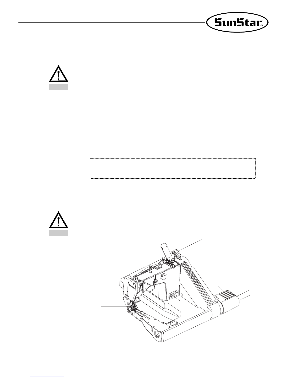
5) Safety devices
ⓐ
Safety label : Things to be kept in mind during operation are described.
ⓑ
Thread take-up lever cover : Prevents the contact between a body part and the thread take-
up lever
ⓒ
Safety plate : Prevents the contact between needles and fingers.
ⓓ
Motor cover : Prevents any potential accidents from occurring while a motor is in
operation.
ⓒ
ⓑ
ⓐ
ⓓ
Page 8
8
Caution
(1)
(2)
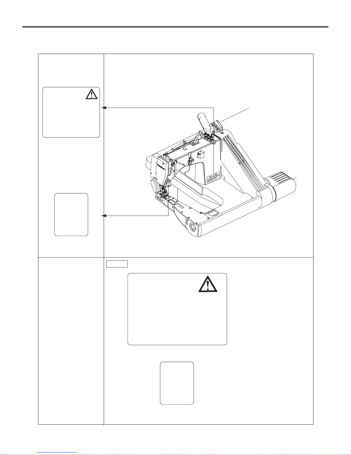
7) Contents of
marks
Caution mark is attached on the machine for safety .
When you operate the machine, follow the directions on the mark.
6) Caution mark
position
CAUTION
주의
Do not operate without finger guard and
safety devices. Before threading, changing
and needle, cleaning etc. switch off
main switch.
손가락 보호대와 안전장치 없이 작동하지
마십시오.
실, 바늘교환시나 청소전에는 반드시 주전원의
스위치를 꺼 주십시오.
CAUTION
주의
Do not operate without finger guard
and safety devices. Before threading,
changing and needle, cleaning
etc. switch off main switch.
손가락 보호대와 안전장치 없이 작동하지 마
십시오.
실, 바늘교환시나 청소전에는 반드시
주전원의 스위치를 꺼 주십시오.
CAUTION
경고
CAUTION
경고
Page 9
9
22
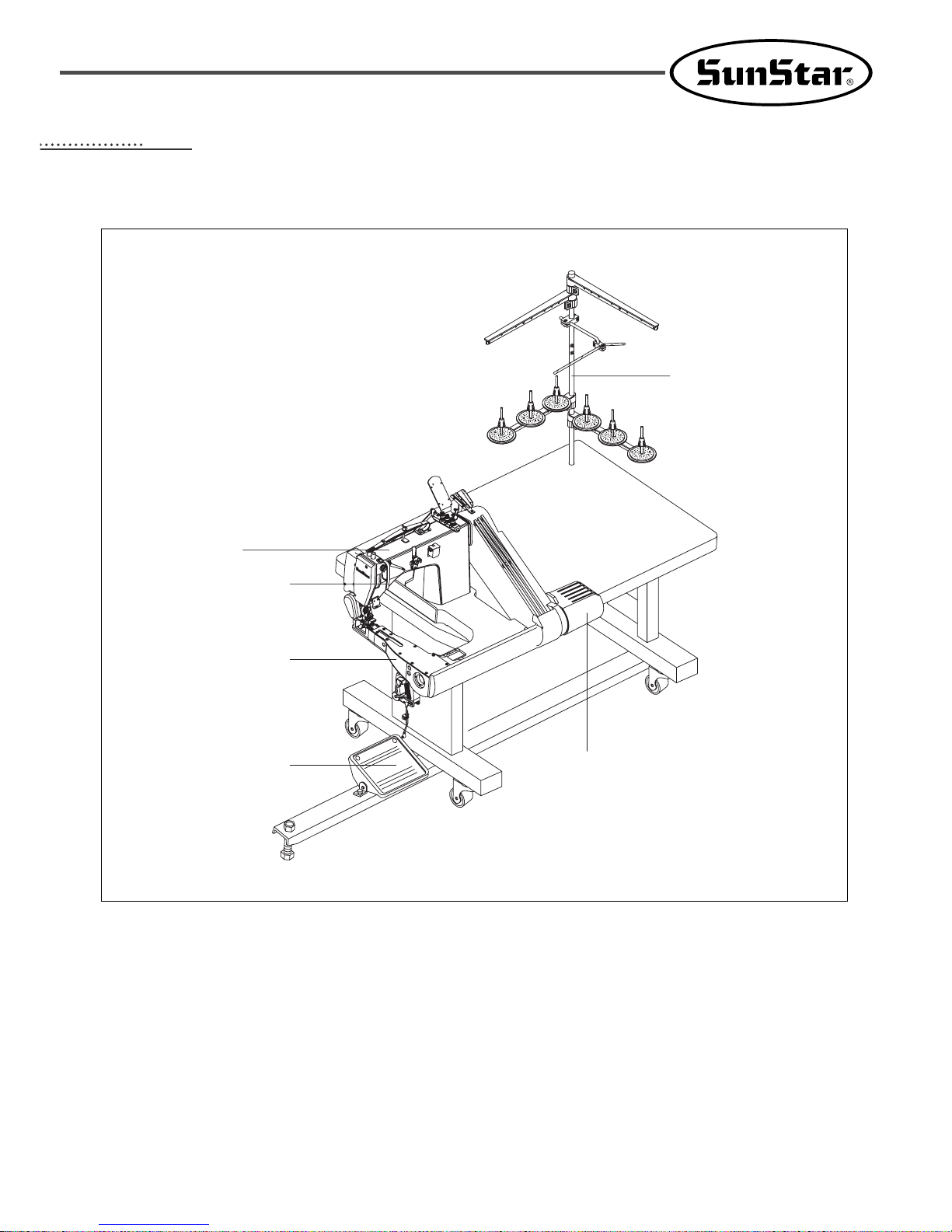
Machine Parts
① Arm
② Bed
③ Main Shaft Motor Cover
④ Pedal
⑤ Thread Stand
⑥ Thread Take-up Lever Cover
⑤
③
④
②
⑥
①
Page 10

10
33
Specifications
Table for Clutch Motor S/M Spin Number
Table for sewing machine rotation number in the event of a clutch motor (external diameter of hand pulley: 80mm)
Computation is according to anumber of regularity rotation.
External diameter of the
sewing machine pulley (mm)
60 65 70 75 80 85 90 95
Number of sewing machine rotation
(rpm)
2583 2799 3014 3229 3445 3665 3875 4091
Usage Heavy weight Materials(Jeans) Light Materials
Stitch Length (mm) 2-4.2 1.1-3.1
Needle Bar Stroke (mm) 35 27
Feed Dog Height (mm) 1.2 0.9
Needle TVX5#Nm22 TVX64NY#11PSU
Attachment 1/4XH, 1/4X 1/4M
Puller Belt-type , Roller Type Puller Roller Type Puller
Presser Foot Climb Sensor O X X X
Presser Bar Pneumatic Type O X O X
Pulley Size X 60Hz : 80, 50Hz : 100 X 60Hz : 80, 50Hz : 100
Main Motor AC Servo (FORTUNA4)
Clutch 2P 60Hz 400W
AC Servo (FORTUNA4)
Clutch 2P 60Hz 400W
Clutch 2P 50Hz 400W Clutch 2P 50Hz 400W
Max. Sewing Speed (spm) 4000 4000 (default setting: 3500) 4000 4000 (default setting: 3500)
Lubrication Oil tank type
Model SC 8200J/01 SC 8200J/02 SC 8200L/01 SC 8200L/02
Power : Main Shaft Motor for Clutch (SMC-1701D), Hand Pulley 80
In case of 3500 RPM : 2P 60HZ(1-phase high-speed) → Motor pulley 80, V belt M Type 43 inch
2P 50HZ(1-phase high-speed) → Motor pulley 100, V belt M Type 44 inch
Page 11

11
44
Installation
1) Table Installation
(1) Table Type
Page 12
12
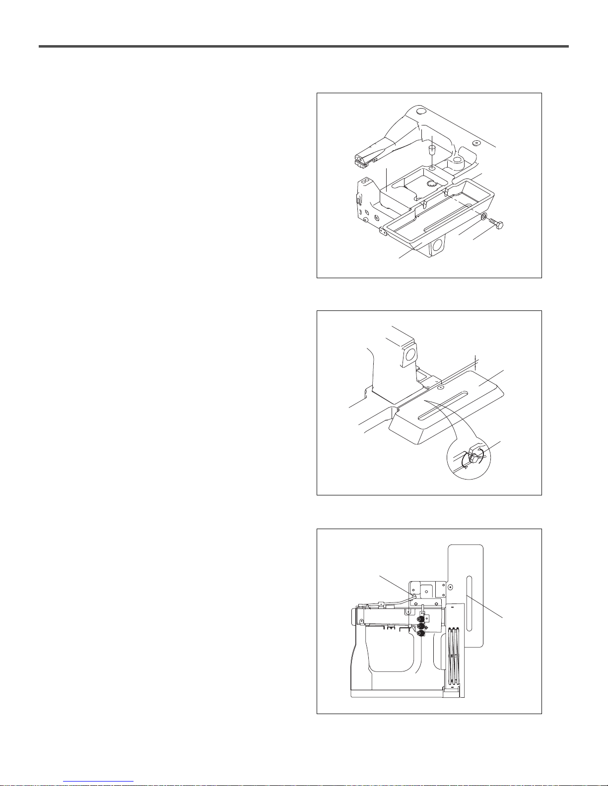
2) Machine Head Installation
A. Assemble the pulley cover base ② to the machine
bed ① using two hexagonal bolts ③ and two
washers ④.
Insert two bar cushions ⑤ into the holes under the
bed.
B. When placing the two hexagonal bolts ③, make sure
that they are deeply inserted into the notches on the
pulley cover base ②. And make sure that the pulley
cover base ② is in parallel with the bed (if not, the
pulley cover might contact the machine pulley).
Parallel
②
③
⑥
⑩
①
⑤
④
③
②
C. Place the machine head on the table and properly
place the hole of the presser bar lifter chain ⑥. Then
locate the belt hole ⑩ in the slant direction from the
presser bar lifter chain. Make the front and back
adjustments.
Page 13

13
D. Assemble the cushion ⑦ to the machine bed and the
pulley cover base using the fixed screw ⑧, and use
the screw ⑨ to fix it to the table.
※ Place the machine head on the table and make
sure it is well balanced. If the balance of the
machine head is not right, lubrication may not
properly take place.
⑧
⑦
⑨
3) Ground Wire Connection
Connect the ground wire to the base and the control box.
A. Connect the ground wire ① to the base using a screw
② and a washer ③.
B. Pass the ground wire ① through the hole on the
table.
C. Connect the ground wire ① to the control box.
4) Attaching the pulley cover(clutch type)
A. Place the belt① on the pulley② and lift the belt.
②
①
Page 14

14
B. With the belt pulled upward, ④ the belt cover (Dn)
③ to the base⑥ using the screws④ and the washers
⑤ (5EA).
C. Insert the belt① into the belt cover (Dn)③ and fix
the belt cover⑦ using the screws⑧ (3EA).
5) Connection to clutch-type pedal
Connect the lap lift lever① and the pneumatic pressure
switch② to Chain ③.
And then connect the pneumatic switch② to Chain ⑤
on the foot pedal④.
④
⑤
③
⑥
⑦
①
⑧
③
①
②
③
⑤
④
Page 15

15
①
②
6m/m TAP
64/9
INCH
TAP
③Parellel
④
⑥
⑤
6) LRP Puller Attachment
A. Replace the no. ①presser foot bolt with the
decelerator bolt.
B. Attach the no.
②
lower roller to the machine.
* Refer to clause H.
C. Attach the no.
③
decelerator to the machine.
※ Adjust the no.
③
È upper/ lower roller horizontally.
D. Replace the pulley of the no.
④
machine with the
decelerator pulley.
E. Connect the no.
⑤
shaft lever with the no.⑥pulley
lever.
Page 16

16
⑦
⑧
64/9 INCH TAP
① ② ③Parellel
F. No. ⑦: Stitch Lever
(The stitch is getting wider by lowering from
1 to 4 one by one)
G. A belt cover should be installed.
※
The belt cover should be cut out like no.⑧for a
brand new machine.
G. H. Lower roller installation
Attach the bracket to the no.①fixed tap hole like no. ②and keep parallel like no.
③
Page 17

17
B. Open the pulley cover of 8200 and fix the pulley of
the puller to the shaft.
C. The position of the timing is the place to adjust the
pulling of the roller.
After operate no. 6 of the manuals, adjust the wheel
movement identically.
6m/m TAP
TIMING
M6×60m/m
M8×25m/m
64/9 inch TAP
7) SRP Puller Attachment
A. Replace the presser foot bolt with the puller bolt.
D. Attach the puller to the body of 8200.
(Use the M8X25m/m, M6X60m/m bolt.)
Page 18

18
Parellel
E. In case fixing the puller, adjust a needle plate base
and a urethane roller base of the puller in parallel.
F. Fix a pulley lever of the puller and a pulley.
G. Install the cover of the puller.
Page 19

19
C. Fix the Puller with the fixation bolt (M10 * 20m/m-3EA)
during attachment.
D. Locate the red-marked thread take-up lever position on the
top.
8) MODEL : BP(Belt Puller Type)
Sewing of several clothes as one (FEED-OFFARM)
Attaching & Setting Puller to Sewing Machine
A. Insert Timing Belt Pulley A into the upper shaft of M/C.
B. Attach the Belt Puller to the M/C.
Timing Belt Pulley A
upper shaft
fixation bolt
thread take-up lever
Page 20

20
F. Adjust the belt tension using idler on the red-marked part to
keep the position unchanged when the puller timing belt is
connected to the timing belt pulley A.
G. Put the belt cover.
E. Fix it to conform to the red-marked part. (The machine and
the time of the puller accord well)
punched mark
idler
belt cover
Saw teeth movement of the machine and the timing of puller need to be united.
Caution
Fix the belt with proper tension not too loosely or tightly.
Caution
Fix the belt cover not to interfere in the machine.
Caution
Page 21

21
I. Connect the fixation screw (M6x40m/m-2EA,M8x20m/m-
1EA) of the red-marked part to the joint before the puller
body is fixed.
J. Fix the puller body to make the needle plate of the machine
and the contact part horizontally.
H. Locate the body of the puller on the red-marked part.
B(exclusive bolt)
joint
Please use the exclusive bolt for belt puller when fixing the part B.
Caution
Surface of the
needle plate
The contact
part on the belt
Page 22

22
L. Stitch width adjustment
Adjust the stitch width of the puller.
(1-1m/m,2-2m/m,3-3m/m, 4-4m/m,5-5m/m)
M. Check
Please change the belt or detach the puller body by pulling
it when checking the machine.
K. Adjust the stopper not to interfere with the puller when the
needle is moving up and down.
stoper
The punched mark should be matched to adjust the stitch width exactly. (Refer to the No.5 item)
Caution
Page 23

23
55
Machine Preparation
1) Oil Supply
A. Make the oil supply slot screw ① pointed upward
and turn the hand pulley. Then remove the screw ①
and supply oil to the oil tank ② until it reaches
above the central line ③.
B. Open the front cover ① and remove the rubber plug
②. Supply lubricant until it reaches the central line
on the oil window ③.
C. Place back the rubber plug ② and close the front
cover ①.
D. Supply one or two drops of oil to the needle bar
lubrication hole ④ once a week.
E. Replace the waste oil tank ⑤ on a regular basis after
long-term use.
①
②
③
④
③
⑤
②
①
If oil is supplied below the central line, oil cannot be sucked into the upper shaft, and sufficiently supplied
to the upper shaft.
Caution
Page 24

24
F. Loosen the oil tank lid screw ① and supply lubricant
until the mark reaches the middle on the oil window
②.
G. Place back and fasten the screw ①.
When the oil level drops below the central line, additional oil must be supplied.
Caution
②
①
Page 25

25
66
Sewing Preparation
1) Needle Installation
2) Lower Thread Placement
Place the lower thread as in the figure below.
A. Turn the hand pulley to make the needle holder ①
reaches the highest position.
B. Loosen the needle fixing screw ②. Make the long
groove of the needle ③ headed forward and then
fasten the fixing screw again ②.
①
③
②
Make sure to turn off the power before needle installation.
Otherwise, injury might occur due to the mistaken operation of the pedal.
Caution
Make sure to turn off the power before lower thread placement.
Otherwise, injury might occur due to the mistaken operation of the pedal.
Caution
Page 26

26
3) Upper Thread Placement
Place the upper thread as in the figure below.
4) Handling of Waste Oil
When the waste oil can beneath the table is filled with
waste oil, remove it to empty the can.
Make sure to turn off the power before lower thread placement.
Otherwise, injury might occur due to the mistaken operation of the pedal.
Caution
When removing or assembling the waste oil can, oil might drop to the floor. Place a cloth, paper, or oil
dish during the oil can removal and assembly.
Caution
Page 27

27
77
Sewing
1) Sewing
A. Turn on the power.
B. Press Pedal A and place the fabric below the presser
bar.
C. Remove a foot from Pedal A.
D. When stepping Pedal B, the machine starts
operating.
E. When the sewing is complete, conduct pseudo
sewing until the cutter ① and trim the thread at the
cutter ①.
①
Properly install all safety devices before using the machine. Otherwise, injury might occur.
Caution
Do not touch the operating sections or the input device during sewing. It may negatively affect the
machine or become the cause of injury.
Caution
In the following situations, please turn off the power. Otherwise, injury might occur due to the mistaken
operation of the pedal.
① Thread placement on the needle
② Needle replacement
③ When the machine is not used or user should be away from the machine for a long time
Caution
Page 28

28
2) Trial Operation (pedal operation method)
A. Lightly step the pedal until B to check if slow sewing
is possible.
B. Press the pedal until C to check if fast sewing is
possible.
C. Press the pedal forward (B or C) and place it at the
neutral A position. Then the needle stops below the
needle plate face (when the lower stop function is
set).
D. When the pedal is pressed until D (or press the pedal
until D and place it to neutral A position), the needle
stops above the needle plate face after trimming.
Do not touch or press with other object the revolving or moving parts while the machine is in operation.
Injury or mechanical damage might occur.
Caution
3) Trial sewing (How to operate a clutchtype pedal)
A. When the pedal① is pressed, the presser foot starts
vertical movement. With the pedal① being pressed,
set the sewing position for trial sewing.
B. Remove a foot from the pedal①, and then the
presser foot starts descending and fixes the sewing
materials.
C. Pressing the pedal② starts operating the trial sewing.
②
①
Page 29

29
88
Thread Tension
1) Thread Tension Adjustment
A. Turn the upper thread adjusting nut ① to properly
adjust the upper thread tension.
B. Turn the lower thread adjusting nut ② to properly
adjust the lower thread tension.
2) Adjustment of Presser Bar Pressure
Use the pressure adjusting nut ① to adjust the pressure
of the presser bar.
①
②
②
Page 30

30
3) Adjusting the pneumatic presser bar
The presser bar① can be adjusted for its pressure in two
steps depending on height.
When the first part② is detected by the second part③,
the pressure is changed. The initial pressure is
2.5~3.5kg, and it changes to 6.5~7.5kg.
A. Loosen the screw④.
B. Lift the presser foot① to the extent of placing it at a
desired position. (Max. lift: 11mm, the default height
of presser foot is 5mm)
C. With the presser foot lifted to the desired position,
move the center of the sensor③ to the most top of
the sensor plate②.
D. Fasten the screw④.
※
The first gauge① is the scale showing the maximum
adjustable pressure of the presser foot (default value:
0.4MPa), and the second gauge② is the scale
showing the minimum adjustable pressure of the
presser foot(default value: 0.1MPa).
②
③
④
①
①
④
③
②
②
Page 31

31
99
Cleaning
1) Daily Cleaning
A. Dust removal
- Open the looper cover and remove thread scraps
and dusts.
- When all dusts are removed, put back the looper
cover.
B. Oil Supply
- See the oil supply section of the manual.
C. Check
- Ensure that thread is properly placed.
- If the tip of the needle is broken, immediately
replace the needle.
- Conduct trial sewing.
①
Page 32

32
1100
Adjustment
⑨
⑩
①
⑧
②
⑦
⑥
①
⑧
①
⑤
③
1) Adjustment of Needle Bar Height
Adjust the height of the needle bar ①.
Make sure that each needle ① is at the center of the needle hole ⑧ on the needle plate ②.
A. Remove the screw ⑨ and then remove the presser foot ⑩.
B. Turn the pulley until the needle bar is located at the lowest position.
C. Loosen the needle bar clamp screw ⑤ and adjust the distance between the bottom of the needle clamp ③ and the
needle plate ② at 14.8mm(For light materials:11.5mm).
※ With the needle clamp adjustment as set forth above, when the needle clamp ③ reaches the highest position,
the distance between the needles ① and the needle plate ② becomes 14mm(For light materials:9mm).
(applicable to heavy and super heavy materials).
D. Remove three screws ⑦ and then remove the needle plate ②.
E. Turn the pulley to place the needles ① and the needle guard ⑥ in parallel. Then adjust the slant of the needle
clamp ③ to remove the space between left, right needles ① and the needle guard ⑥.
Use the three screws ⑦ to assemble the needle ②. Check that the needles ① are at the center of the needle holes
⑧, and then fasten the needle bar clamp screw ⑤.
F. Use the screw ⑨ to assemble the presser foot ⑩.
Page 33

33
2) Adjustment of Needle and Looper Timing
When the needle ① descends, and the lowest looper ②’s backward movement is complete, the distance between the
center of the needle and the looper becomes 2.7~2.9mm.
A. Remove the presser foot, the needle plate, and the feed dog.
B. Turn the pulley until the looper ②’s backward movement is complete.
C. Loosen the two adjusting screws ⑦ on the lower shaft pulley ⑥.
D. Turn the pulley toward the user side until the needle ① reaches the lowest position.
E. Tightly fasten the two adjusting screws ⑦.
F. Loosen the adjusting screw ⑧ and move the looper holder ⑨ in the arrow direction until the distance between the
needle center and the tip of the looper becomes 2.7~2.9mm. The tightly fasten the adjusting screw ⑧ again.
G. Check if the looper thread eyes match needle eyes while the loopers are moving back and forth.
H. Assemble the presser foot, the needle plate, and the feed dog.
3) Needle Avoiding Looper Timing
When the looper moves forward, it moves behind the needle. When the looper moves backward, it moves in front of
the needle. For the forward movement, adjust the distance between the needle and the looper at around 0.05~0.1m.
A. Remove the forward feed arm cover ①.
B. Adjust the timing of the looper heading forward and backward. The adjusting screws on the back which move in
the same direction of the cam moving back and forth should match the screw adjusting hole ③. Then, the
adjusting screws on the back which move in the same direction of the cam moving up/down should match the
looper connecting road adjustment hole ②. For adjustment, loosen the adjusting screw on the front which moves
in the same direction of the cam moving back and forth. Then loosen the adjustment screw on the back to adjust
the cam moving back and forth. When adjustment is completed, tightly fasten the two adjusting screws.
C. Loosen the looper holder screw ④. When the tip of the next looper and the needle center are in a straight line,
move the looper holder ⑤ in the arrow direction to adjust the distance between them at 0.05~0.1mm. Do not
move the looper holder ⑤ in any other direction than the instructed direction. If you did, see “10-2. Adjustment
of Needle and Looper Timing” in page 16 for making adjustment.
D. Assemble the forward feed arm cover ①.
⑦
⑥
①
②
⑧
⑨
(Looper moving forward) (Looper moving backward)
①
②
③
④
⑤
Page 34

34
4) Adjustment of Needle Bar Guide
When the stitch length is the minimum and the looper moves toward the needle, the distance between the needle
guard and the needle should be 0.2mm.
The height should remain as low as possible to the extent that the looper does not break.
A. Adjust the stitch length to be minimal (see page 12).
B. Spin the pulley toward the user side to make the needle center and the looper in the straight line.
C. Loosen the adjusting screw ③. Then move the needle bar guide to set the distance between the needle bar guide
bottom ① and the needle to be 1~2mm.
D. Tightly fasten the adjusting screw ③.
E. Loosen the adjusting screw ④. To set the distance between the needle bar guide and the needle at 0.2mm, move
the needle bar guide left and right.
F. Tightly fasten the adjusting screw ④.
5) Adjustment of Feed Dog Height
Adjust the highest part of the feed dog to be 1.2mm(For
light materials:0.9mm) above the needle plate surface
when the feed dog ① is at the highest position.
Adjust the height of the feed dog ① by spinning the
feed bar eccentric shaft ②.
A. Spacer Installation (for denim sewing)
If irregular stitches occur during the sewing of super
heavy materials, adjust the sub feed dog to the
accurate height using the spacer.
- Remove the adjusting screw ① and the sub-feed
dog ②.
- Locate the spacer ③ below the sub-feed dog ②
and fasten the adjusting screw ①.
※ Spacer is included in the parts box.
④
③
①
①
②
When setting the stitch length depending on fabrics and thread used, the closer the needle bar guide and
the needle becomes, the better the sewing result is.
Caution
Page 35

35
6-1) Adjustment of Thread Release Lever
Adjust the thread release lever's thread hole center to be
7~9mm above the thread hole center on the upper thread
tension adjusting device when the needle bar is at the
lowest position.
A. Turn the pulley until the needle bar descends to the
lowest position.
B. Loosen the screw ① and move the thread release
lever ② up and down to adjust the thread release
lever thread hole center to be 7~9mm above the
thread hole center on the upper thread tension
adjusting device.
C. Fasten the adjusting screw ① again.
※ As the thread release lever moves higher, the
stitches become firmer.
6-2) Adjustment of Thread Release Lever
When the needle bar is at the lowest position, adjust to
place the center of the thread release lever thread hole at
2 to 3mm below from the center of the thread hole of the
thread take-up lever thread guide.
A. Turn the pulley until the needle bar is lifted to the
highest position.
B. Loosen the screw① and adjust the thread release
lever② up or down to place the center of the thread
release lever tread hole at 2~3mm below from the
tread guide’s thread hole.
C. Fasten the adjusting screw ① again.
①
7~9mm
①
2~3mm
6~7mm
②
7) Adjustment of Thread Take-up Guide
Adjust the distance between the thread take-up's thread
guide hole and the thread take-up guide's upper part to
be 6~7mm(For light materials:3mm).
A. Turn the pulley toward the user's position when the
needle bar reaches the lowest position.
B. When the screw ① is loosened, move the thread
take-up guide ② up and down to set the distance
between the upper part of the thread take-up guide ②
and the thread guide hole to be 6~7mm.
C. Fasten the screw ①.
※ As the thread take-up guide ② moves higher, the
upper thread loops become larger.
①
②
Page 36

36
9) Adjustment of Thread Release Shaft
Adjust the thread release shaft to ensure when the
presser foot ascends, the thread tension discs are
released and to ensure when the presser foot descends,
the thread tension discs are tightened.
A. Loosen the adjusting screw ①.
B. Spin the thread release shaft ② to make the thread
tension discs start loosening when the presser foot is
4mm above the needle plate.
C. When the adjustment is complete, tightly fasten the
adjusting screw ①.
10)
Adjustment of Lower Thread T ake-up T iming
When the looper starts moving backward, make
adjustment to let the lower thread take-up ① contact the
thread ② and 7mm away from the lower thread take-up
base ③.
A. Insert the screwdriver into the adjustment hole on the
lower thread take-up base and loosen the two
adjusting screws④.
B. Lift the lower thread take-up ① from the lower
thread take-up base by 7mm.
C. Tightly fasten the two screws ④ after adjustment.
②
①
8)
Adjustment of Upper Thread Adjusting Cam
The maximum tolerance between the upper thread
tension adjuster ② and the upper thread tension plate ③
is 0.5~0.7mm (2-needle) or 0.8~1.0mm (3-needle).
Loosen the adjusting screw ① and move the upper
tension adjuster ② in and out to set the maximum
tolerance between the adjuster ② and the upper thread
tension plate ③ to be 0.5~0.7mm (2-needle) or
0.8~1.0mm (3-needle).
※ If tolerance between the upper thread adjuster ② and
the upper thread tension plate ③ is reduced, the
tension gets higher.
①
②
③
Page 37

37
12) Adjusting position of the belt puller
The belt puller is adjustable in four directions including
up, down, left, and right.
When the needle is located below, the belt should
closely contact the needle plate. Otherwise, smooth
seaming is difficult to get.
11) Lapper Installation
Insert the lapper guide pin into the overall hole on the
upper bed cap. Check if the end of the lapper is not too
close to the presser foot.
Page 38

38
A. Unfasten the screws①, ②.
B. Turn the screws③, ④ with a driver to adjust the
position of the belt puller. The belt should closely
contact the sunken part of the needle plate without
space, and it should not be contacted by the needle
bar when the needle bar is at its lowest position.
C. After adjustment is completed, tightly fasten the
screws①, ②.
13) Fixing without puller
The puller can be fixed while being pushed backward
and it can be fixed either at the angle of 50°or 100°.
A. Loosen the screw ①.
B. Lift the belt puller while the screw ① is pulled up.
C. Fasten the screw ①.
①
②
③
④
①
Page 39

39
Roller Timing Adjustment Spot
⑩
⑫
⑪
※ Checkpoints
14) Decelerator Timing Adjustment
When a saw teeth of the machine starts to move up and
pushes the stuff out, adjust the roller of decelerator to go
around.
A. The decelerator is bearing type so if the angle is
turning, part of the bearing can be damaged or be
generated heat. After installation, therefore, check as
follows
B. Unfasten the no.
⑩
bolt, shake no.⑪stitch length
lever back and forth more than 3 times leading to
place no.
⑩
shaft lever its position.
After that, match no.
⑫
arrow to the other arrow and
fix the no.
⑩
bolt.
Page 40

40
Stitch Adjustment Method
Descending from no.1
toward no.5, the stitch is
getting longer.
15) Adjustment of Puller Feeding Amount
- Shaft lever(PART NO.12) function can choose the
feeding of roller(quantity of motion/the stitch role of
sawing machine).
A(quantity of motion) : Large=5.2m/m, Small=2.3m/m
B(quantity of motion) : Large=4m/m, Small=2m/m
C(quantity of motion) : Large=3.3m/m, Small=1.3m/m
16) Speed Lever Stitch Length Adjustment
- The shaft lever(PART NO.25) stitch is adjusted as the
scale is widened and it can be adjusted by changing the
setting position.
- Timing adjustment
Unfasten part no.13, shake no.25 back and forth more
than 5 times.
After the position of bearing is settled, adjust to the place
which the arrow direction is matched and fix the part no.13.
(See Decelerator Timing Adjustment of the manuals)
17) P.S.W-I Stitch Length Adjustment
* LRP Type(PART NO.66), SRP Type(PART NO.55)
Generally use by fixing to the standard position (A) part
but in case of using the stitch longer, position (B) can be used.
In case of moving the position of shaft lever(PART NO.12),
be sure that the power switch of M/C is in the OFF position and the power cord is unplugged.
Caution
Page 41

41
18) Ascending Momentum of the Ruller
* LRP Type(PART NO.77), SRP Type(PART NO.71)
-> the quantity of motion in case of working with a
machine (13m/m).
* The quantity of motion when part no.29(manual lever) is
lifted by hand (15m/m~25m/m)
19) Bearing Replacement
- Parts Life [LRP Type (PART NO.54, NO.57), SRP Type
(PART NO.91, NO.95) 5R BEARING]
Parts can be used for 2.5 to 3.5 years although there are
some gaps according to the workload.
-Replacement Time
Replace them when the machine stitch mismatches to the
stitch of the puller due to the pulling malfunction with
long use.
20) Breakdown of TENSION DISK & E-RING
LRP Type(PART NO.62~NO.76), SRP Type(PART NO.51~NO.65)
- Engine structure has the pulling function of piller and built-in
grease, does not need oil.
13m/m
15m/m~25m/m
Need not use oil due to the oilless bearing. In case of refueling unnecessary oil, the stuff can be tainted so
the use of oil is prohibited.
Caution
If the thread winds around the engine structure or the parts are damaged by mistakes, the function of puller
can be out of order so do work with care.
(The damage caused by a careless worker cannot be repaired for free.)
Caution
 Loading...