

Page 1

USER S MANUAL
SC 7900-Series
R
1) Read all instructions before using the
machine to prevent trouble.
2) Keep the instructions and refer to it during
machine failures.
Page 2

Best Quality
Best Price
Best Service
R
1. Thank you very much for buying a HIGH-SPEED OVERLOCK sewing
machine.
SUNSTAR will satisfy you by manufacturing the industrial sewing machine
with refined design, improved durability, great power, perfect performance,
variable functions based on skills and experience.
2. Please read this manual thoroughly before use.
3. This manual can be changed the contents without prior notice to improve
the functions.
4. This is designed and manufactured as an industrial machine. Do not use this
machine for other than its intended use.
Page 3
Page 4

4
Table of Contents
1. SAFETY RULES ------------------------------------------------------------------------------------- 6
1) MACHINE DELIVERY ------------------------------------------------------------------------------------------- 6
2) MACHINE INST ALLATION------------------------------------------------------------------------------------- 6
3) MACHINE REPAIR ------------------------------------------------------------------------------------------------ 6
4) MACHINE OPERATION ----------------------------------------------------------------------------------------- 7
5) SAFETY DEVICE -------------------------------------------------------------------------------------------------- 7
6) PLACEMENT OF CAUTION STICKERS -------------------------------------------------------------------- 8
7) CONTENTS OF CAUTION STICKERS----------------------------------------------------------------------- 8
2. ENTIRE STRUCTURE ----------------------------------------------------------------------------- 9
3. SPECIFICATIONS ----------------------------------------------------------------------------------- 10
4. INSTALLATION -------------------------------------------------------------------------------------- 11
1) T ABLE INSTALLATION------------------------------------------------------------------------------------------ 11
2) M/C INST ALLATION---------------------------------------------------------------------------------------------- 13
3) THREAD GUIDE FOR ST AND SUPPORT INST ALLATION -------------------------------------------- 14
4) GROUND WIRE CONNECTION------------------------------------------------------------------------------- 14
5) AIR-COMPRESSED PRESSURE BAR LIFTER INSTALLA TION-------------------------------------- 15
6) DIRECT MOTOR INSTALLA TION---------------------------------------------------------------------------- 16
7) AIR-COMPRESSED TREAD TRIMMING DEVICE (Optional) INSTALLA TION------------------- 17
8) AIR-COMPRESSED DEVICE INST ALLATION ------------------------------------------------------------ 18
5. LUBRICATION---------------------------------------------------------------------------------------- 20
1) OIL--------------------------------------------------------------------------------------------------------------------- 20
2) LUBRICATING OIL ----------------------------------------------------------------------------------------------- 20
3) OIL GAUGE/OIL WINDOW------------------------------------------------------------------------------------- 20
4) LUBRICATING OIL EXCHANGE------------------------------------------------------------------------------ 21
5) OIL PRIMING------------------------------------------------------------------------------------------------------- 21
6) LUBRICATING OIL REPLENISHMENT --------------------------------------------------------------------- 21
7) OIL FILTER CLEANING ----------------------------------------------------------------------------------------- 22
6. STANDARD ADJUSTMENTS ------------------------------------------------------------------- 23
1) NEEDLE-------------------------------------------------------------------------------------------------------------- 23
2) NEEDLE INST ALLATION--------------------------------------------------------------------------------------- 23
3) THREADING-------------------------------------------------------------------------------------------------------- 24
4) THREAD TENSION ADJUSTMENT -------------------------------------------------------------------------- 25
5) PRESSER FOOT ADJUSTMENT------------------------------------------------------------------------------- 25
6) PRESSER FOOT PRESSURE ADJUSTMENT--------------------------------------------------------------- 26
7) VERTICAL ADJUSTMENT OF PRESSER FOOT---------------------------------------------------------- 27
8) MAIN FEED ADJUSTMENT------------------------------------------------------------------------------------ 27
9) DIFFERENTIAL FEED ADJUSTMENT ---------------------------------------------------------------------- 28
10) THREAD LUBRICATING DEVICE -------------------------------------------------------------------------- 29
11) OVERLAP WIDTH ADJUSTMENT OF UPPER SEWING MACHINE------------------------------- 29
12) USING A LAP FORMER---------------------------------------------------------------------------------------- 30
Page 5

5
7. DETAILED ADJUSTMENTS --------------------------------------------------------------------- 31
1) THREAD TENSION ADJUSTMENT -------------------------------------------------------------------------- 31
2) LOOPER THREAD TENSION ADJUSTMENT ------------------------------------------------------------- 32
3) UPPER THREAD TENSION ADJUSTMENT---------------------------------------------------------------- 33
4) NEEDLE HEIGHT SETTING------------------------------------------------------------------------------------ 33
5) UPPER THREAD RET AINER----------------------------------------------------------------------------------- 34
6) ADJUSTMENT OF NEEDLE AND LOOPER TIMING---------------------------------------------------- 35
7) ST ANDARD POSITION OF NEEDLE GUARD------------------------------------------------------------- 36
8) FEED DOG HEIGHT SETTING--------------------------------------------------------------------------------- 37
9) EXCHANGE OF PRESSER FOOT ----------------------------------------------------------------------------- 38
10) EXCHANGE OF PRESSER FOOT SPRING PLATE A--------------------------------------------------- 40
11) BLADE EXCHANGE AND ADJUSTMENT---------------------------------------------------------------- 41
8. AIR-COMPRESSED THREAD TRIMMER (OPTIONAL) MANUAL ----------------- 43
1) CONSIDERATIONS BEFORE USING------------------------------------------------------------------------- 43
2) MODEL NUMBER SETTING ----------------------------------------------------------------------------------- 43
3) SENSOR SETTING METHOD ---------------------------------------------------------------------------------- 43
4) RELATED P ARAMETER----------------------------------------------------------------------------------------- 45
5) THREAD TRIMMING MODE SETTING--------------------------------------------------------------------- 45
6) THREAD TRIMMING RANGE SETTING ------------------------------------------------------------------- 47
Page 6
6
SAFETY RULES
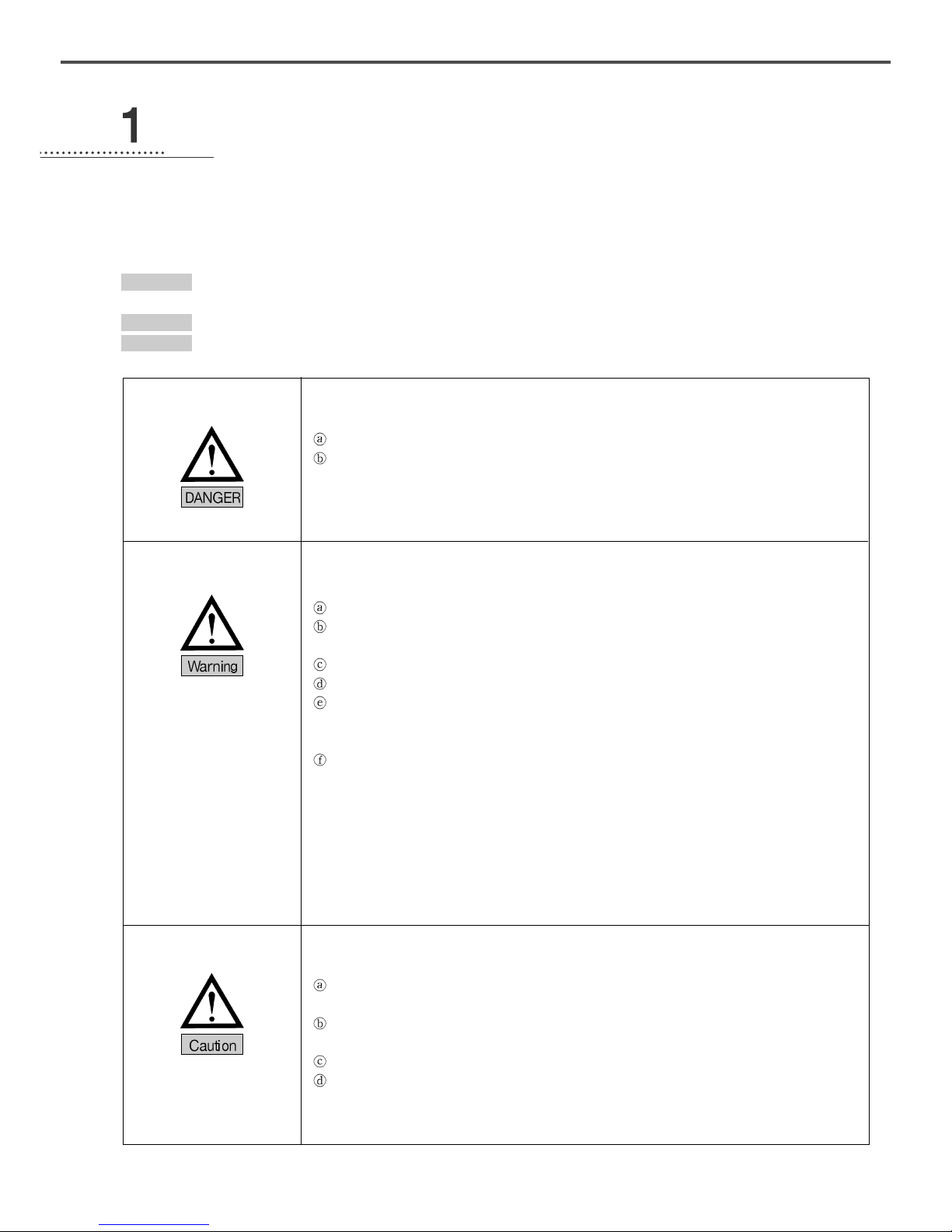
The following set of safety rules categorized as Danger, Warning and Caution indicates possibilities of physical or property
damages if not fully observed.
DANGER : These safety instructions must be observed to be safe from danger when installing, delivering, or
maintaining the machine.
WARNING : These safety instructions must be observed to be safe from machine injuries.
CAUTION : These safety instructions must be observed to prevent machine errors.
1) Machine Delivery
2) Machine Installation
3) Machine Repair
Only qualified technicians who are familiar with the safety instructions should carry the
machine. Make sure to fully observe the following instructions when carrying the machine.
The machine should be carried out by two or more people.
Clean oil spots to prevent accidents when delivering.
Installation environment may incur machine malfunction or breakdown. Make sure to meet
the following conditions.
Undo a package from the top in order. Beware nails in wooden box.
Dust and humidity can cause pollution and corrosion of the machine. Air conditioner
should be equipped and cleaned regularly.
Do not expose the machine directly to the sun.
Allow at least 50cm of space on each side of the machine for convenient maintenance.
Explosion hazard
Do not operate machine in explosive atmospheres, where aerosol spray is used in large
quantity or oxygen is controlled.
The lighting is not offered because of the nature of the machine, the lighting should be
install in the workspace by users.
[Reference] details of the machine installation are illustrated in 4. INSTALLAION.
Only SUNSTAR MACHINERY Co.,Ltd-trained and selected repair engineers should go
repair work.
Turn off the power before cleaning or repairing the machine. Wait for 4 minutes so the
machine electricity is completely discharged.
Do not change the specifications or any parts on the machine without confirmation from
SUNSTAR MACHINERY Co.,Ltd. Such change may cause safety accidents.
Use only SUNSTAR MACHINERY Co.,Ltd parts when repairing machine.
Put all safety cover on after repairing.
Page 7
7
SC 7900 Series is designed for applying sewing to knitwear and other similar materials.
Read thoroughly the following instructions.
Read thoroughly and fully understand the manual before operating the machine.
Dress for safety.
Keep your hands or head away from the moving parts of the machine such as needle,
looper, spreader, take-up lever, and pulley when the machine is in operation.
Do not remove the safety valve and all kinds of covers when the machine is in operation.
Be sure to connect the ground wire
Be sure the main power is turned off and the power switch is set to OFF before opening
the cover of any electrical component or control box.
Turn the machine off when threading needles or inspecting the finished sewing.
Do not press the pedals when you turn on the power.
Install the machine away from strong electromagnetic wave such as high frequency
welder as far as possible.
[WARNING]
When you operate machine, you should put the cover on to prevent physical injury by the
gear or other parts. Turn off the power before inspecting or adjusting.
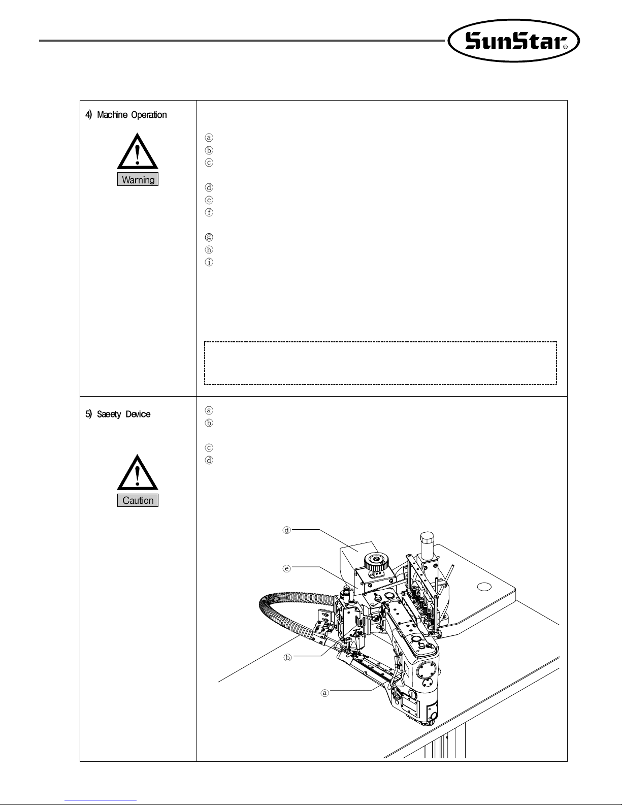
Safety Label: Note directions for sewing machine use
Thread take-up Cover: Device to prevent finger to come in contact with the thread takeup.
Base cover: Device to prevent accidents during rotation of motor.
Motor cover: Device to prevent accidents during rotation of motor.
Page 8
8
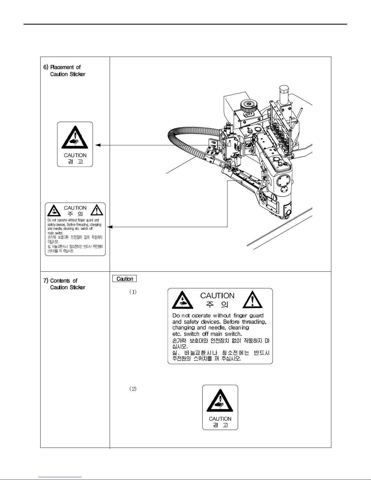
CAUTION STICKERS is attached on the machine for the safety.
Read thoroughly the manual before operating the machine.
Page 9
9
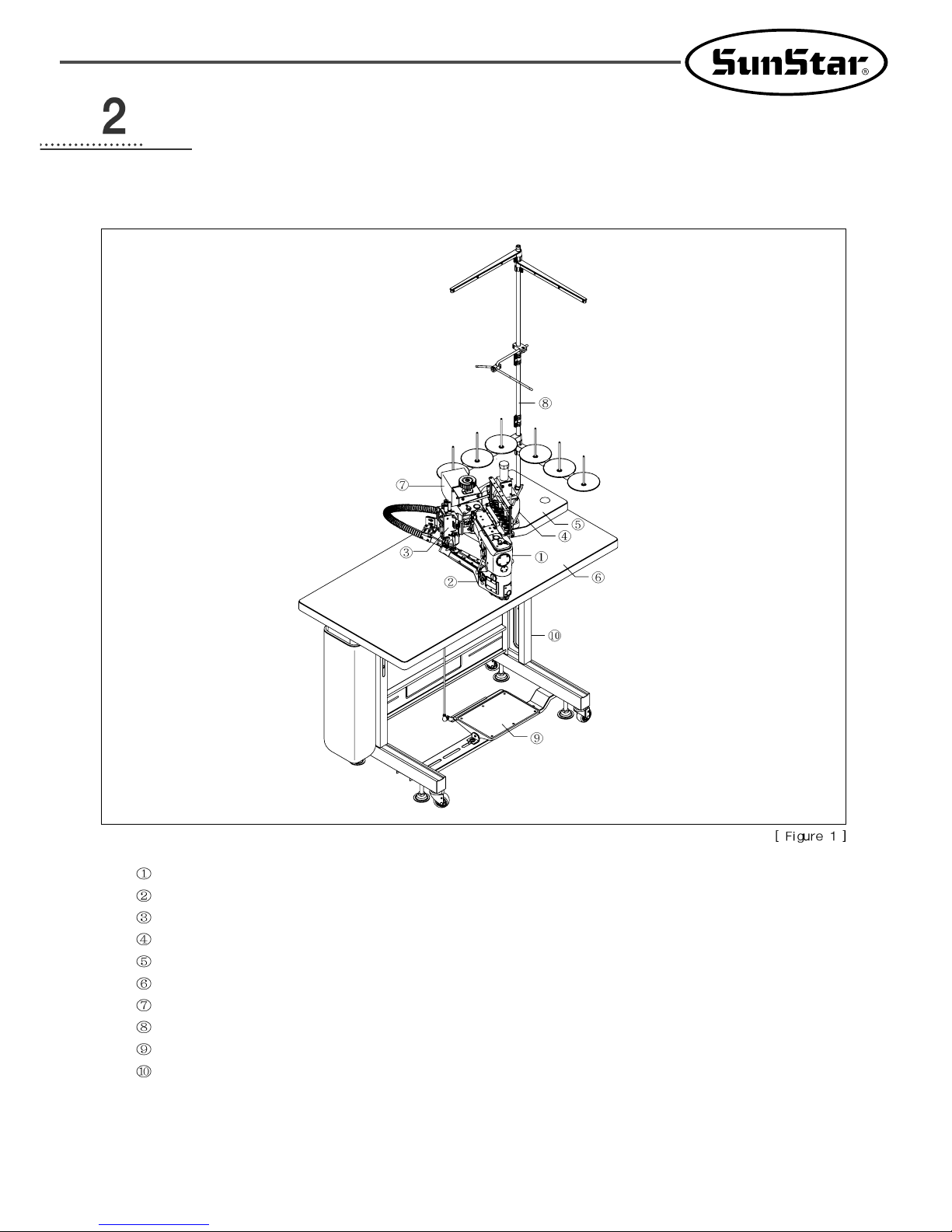
ENTIRE STRUCTURES
Arm
Bed
Head
Arm support
Arm support table
Table
Motor cover
Spool thread stand
Pedal
Table legs
Page 10

10
SPECIFICATIONS
Explanation
Stitch form
Use
Sewing speed
Stitch width
Needle
Needle distance
Needle bar stroke
Presser foot lift
Feeding volume adjustment system
Differential feed ratio
Differential feed ratio adjustment system
Lubrication system
Used oil
Oil pan capacity
High-speed Cylinder bed 4-needle interlock sewing machine (the Arm type)
ISO 406, 605, 608
General sewing (knitwear)
4,200 s.p.m (in case of intermittent operations)
1.6mm~2.5mm
Stitches per 25.4mm: 10~16, stitches per 30mm: 12~19
Sewing machine needles: Groz-Beckert UY118GKS
Retainer needles: Groz-Beckert UY36211
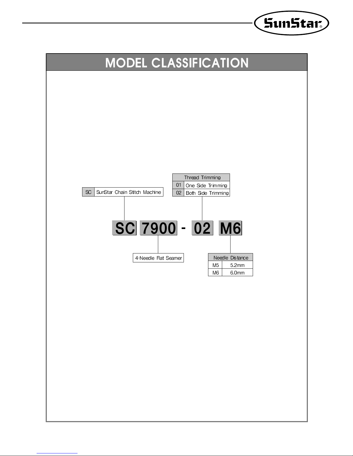
M5 : 5.2mm
M6 : 6.0mm
30mm
Type 01: 8mm, type 02: 6mm at the highest point
Adjustment link
Max. Forward differential feed ratio=1.0:1.5
Max. Reverse differential feed ratio=1.0:0.7
Adjustment lever
Automatic lubrication by gear pump
General sewing machine oil ISO VG 22
The lower part of bed: 100cc
The inner part of arm: 100cc
Page 11
11
INSTALLATIONS
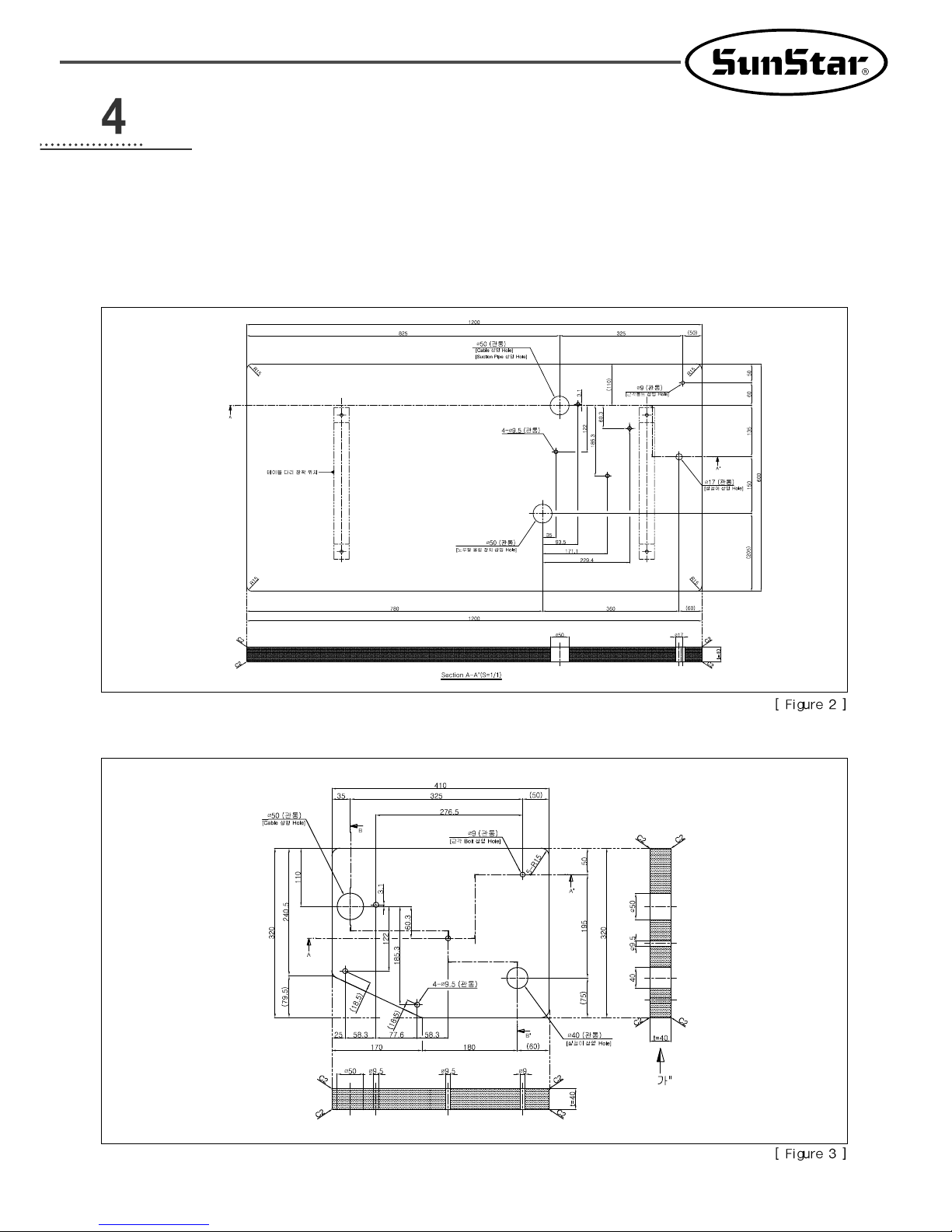
1) TABLE INSTALLATION
(1) T able type
A. T able
B. Arm support table
Page 12

12
(2) T able installation
Fix a dust bag with the screw like the figure 4.
Assemble a control box like the figure 4.
Page 13
13
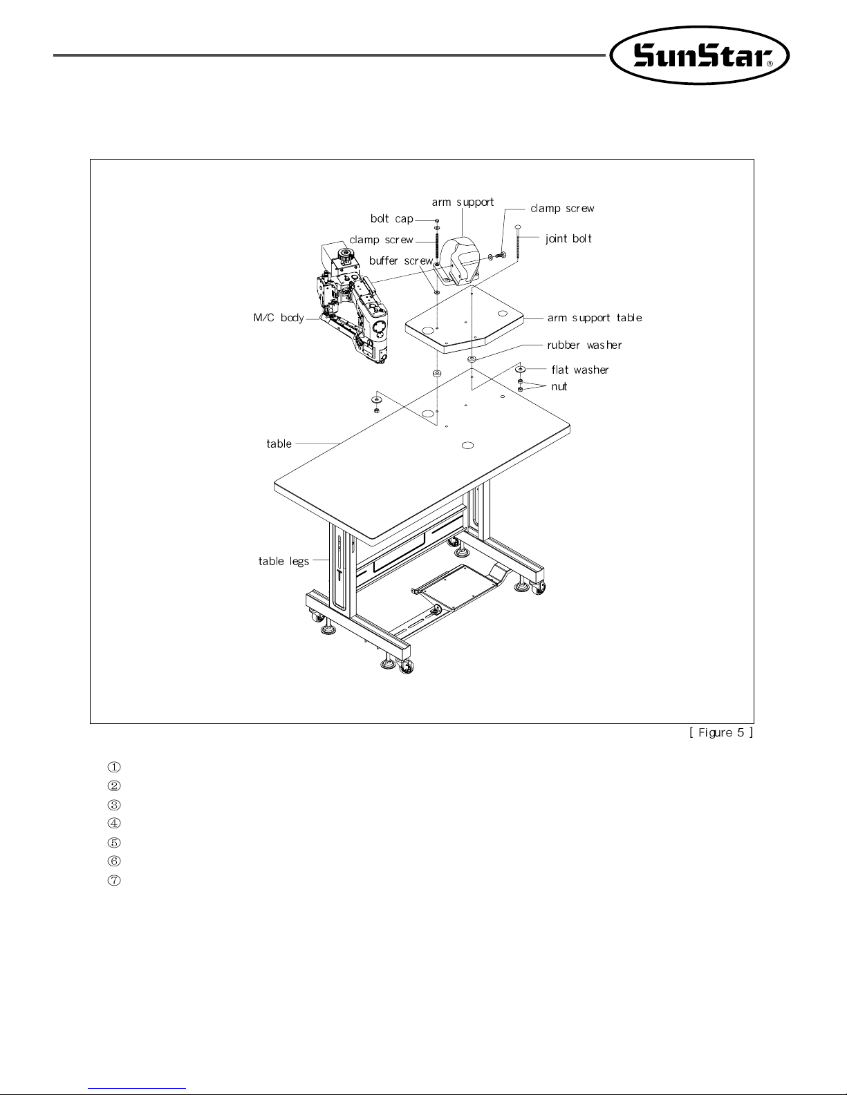
2) M/C INSTALLATION
Assemble table legs.
Put the assembled legs and a table together.
Place a rubber washer on the linking part of the table and put a arm support table on it.
Set a buffer rubber onto the arm support connection then lift a arm support up.
Combine a clamp screw for the arm support putting cap nut and a nut with the arm support.
Combine the arm support table with the table using joint bots and nuts.
Combine the M/C body with the arm support using the clamp screw.
Page 14
14
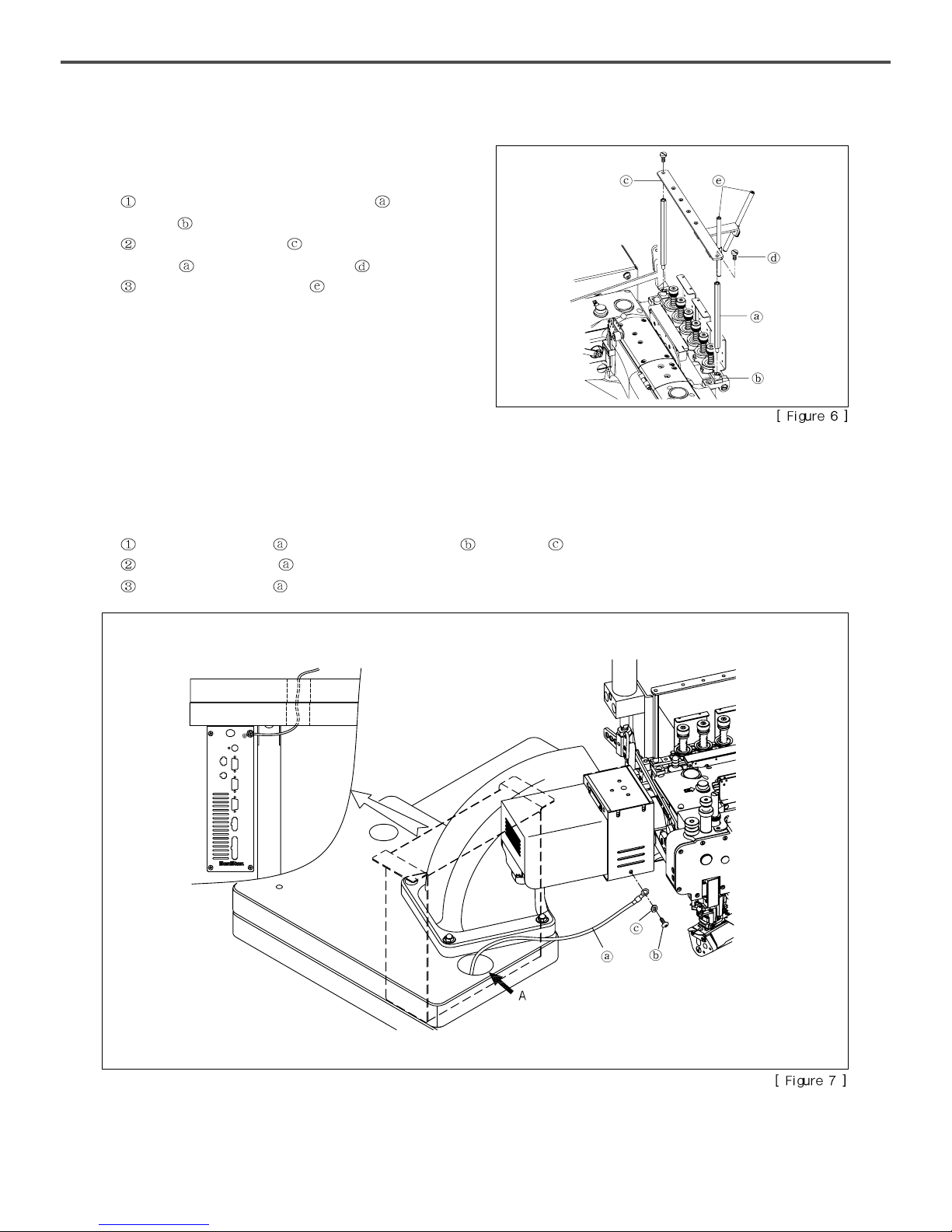
3) THREAD GUIDE FOR STAND SUPPORT
INSTALLATION
Assemble a thread guide for stand support onto a support
bracket
.
Put the thread guide plate on the thread guide for stand
support
and then fix it with the screw .
Assemble the thread guide pipe .
4) GROUND WIRE CONNECTION
Connect a ground wire to the base cover and the control box.
Connect the ground wire to the base cover using a screw and a washer .
Penetrate the ground wire the hole A on the table.
Connect the ground wire to the control box.
Page 15
15
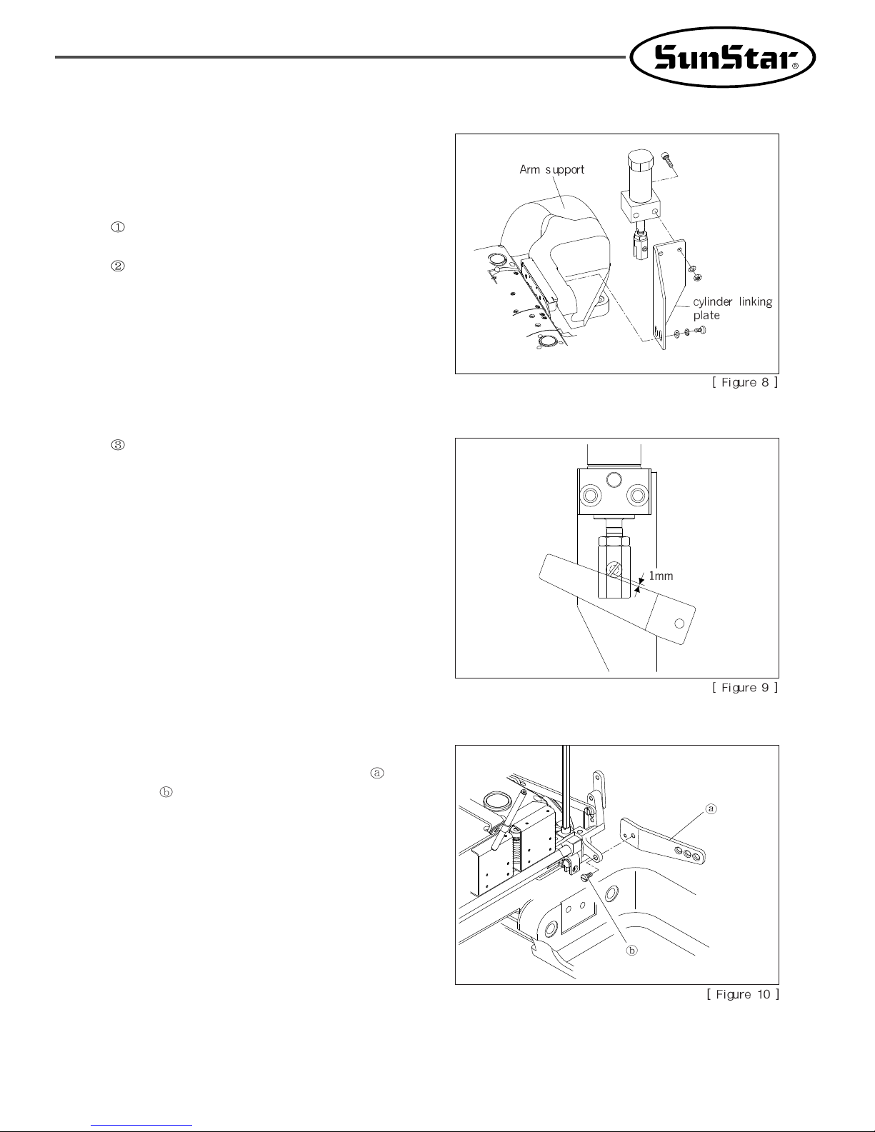
5) AIR-COMPRESSED PRESSURE BAR LIFTER
INSTALLATION
An air-compressed pressure bar lifter is composed of several
parts.
Assemble an air-compressed cylinder and an assembled
device with cylinder knuckles to the cylinder linking plate.
Assemble the cylinder linking plate with the arm support.
Adjust the cylinder knuckle to make the distance of 1mm
between the cylinder knuckle short screw and the knee lifter
connection lever. (Refer to the figure 9)
(1) Knee lifter connection leve
Assemble the knee lifter connection lever
with the
screw
.
Page 16

16
Assemble the coupling A to be 11.2mm in the arm-fix bracket.
(Refer to the figure 12)
Fix the coupling A( ) to the main crank shaft. (Refer to the figure 13)
Assemble the motor parts( ) and the motor cover. (Refer to the figure 11)
6) DIRECT MOTOR INSTALLATION
Assemble the arm-fix bracket and the assembled part with the arm. (Refer to the figure 11)
Page 17

17
7) AIR-COMPRESSED THREAD TRIMMING DEVICE (OPTIONAL) INSTALLATION
An air-compressed thread trimming device is composed of several parts. (G-CT-0002)
Assemble the thread cutting block and the thread cutting base at
the center of the front and the side. (Refer to the figure 15)
Y ou should be careful no to intrude into the sensor part when setting the suction pipe.
Page 18

18
8) AIR-COMPRESSED DEVICE INSTALLATION
(1) Specification
Connect the air hose to the manifolder block of the filter regulator and solenoid valve.
Connect the air hose to the upper fitting of the air-compressed cylinder and the left side of the upper solenoid valve.
Connect the air hose to the lower fitting of the air-compressed cylinder and the right side of the upper solenoid valve.
Connect the air hose to the suction pipe and the lower solenoid valve.
Connect the cable which is written in PF linking to the control box to the upper solenoid valve.
Connect the cable which is written in CL linking to the control box to the lower solenoid valve.
After installing to the table, open the air-compressed regulator of the filter regulator and set the compressed air at the
0.4~0.5 bar.
Page 19

19
(2) Air-compressed device (optional) installation
Connect the air hose to the manifolder block of the filter regulator and solenoid valve.
Connect the air hose to the upper fitting of the air-compressed cylinder and the left side of the solenoid valve A.
Connect the air hose to the lower fitting of the air-compressed cylinder and the right side of the solenoid valve A.
Connect the air hose to the suction pipe and the solenoid valve B.
Connect the air hose to the cutter cylinder and the solenoid valve C.
Connect the cable which is written in PF linking to the control box to the solenoid valve A.
Connect the cable which is written in CL linking to the control box to the solenoid valve B.
Connect the cable which is written in TT linking to the control box to the solenoid valve C.
After installing to the table, open the air-compressed regulator of the filter regulator and set the compressed air at the
0.4~0.5 bar.
Page 20

20
LUBRICATION
1) OIL
Use the industrial sewing machine oil which is provided by SUNSTAR or SF oil from YANASE.
2) LUBICATING OIL
This sewing machine is shipped without oil. To use the machine without breakdown, remove the oil cap screw , and then
lubricate oil to the top limit of the oil gauge
, .
3) OIL GAUGE/OIL WINDOW
Check the oil gauge , before operating the sewing machine. Lubricate oil when the oil indicator or the oil surface (refer to the
figure 18, 19) is under the 2 lines. Check the spattering of the oil through the oil window
, when operating the sewing machine.
Page 21
21
4) LUBRICATING OIL EXCHANGE
Change the oil during the first month every 200 hours and then change it two times per year. If not, the life of the sewing machine is
going down.
Discharge the lubricating oil by loosening the oil outlet screw , .
After discharging, fix the oil outlet screw and firmly.
Refer to the 2) LUBICATING OIL for lubricating.
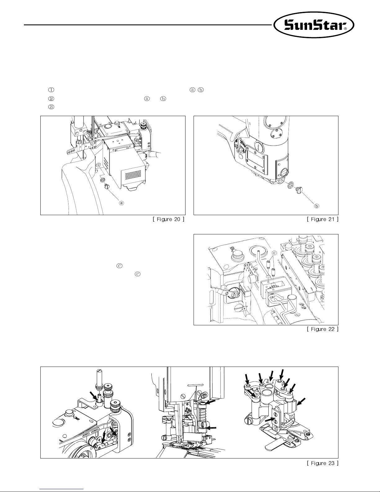
5) OIL PRIMING
Prime the oil before operating new machine or the machine not
to use for a long time.
After remove the upper screw
of oil pump housing and oil
priming, then fix it again with the screw
.
(Refer to the figure 22)
6) LUBRICATING OIL REPLENISHMENT
Lubricate about 3~4 drops of oil into the oil hole[Figure 23] every one time a month. If the oil leaks out, the oil spots could be
occurred on the parts. Therefore wipe out after replenishing oil.
Page 22

22
7) OIL FILTER CLEANING
Clean the suction filter and the oil filter 2~3 times a year. Clean as followings.
- Oil filter cleaning
Discharge the lubricating oil by loosening the oil outlet
screw
After discharging, fix the oil outlet screw firmly.
Separate the oil pan from the bed by loosening the oil pan
clamp screw
.
Remove the foreign substances by pulling out a oil filter .
Assemble it again in reverse order.
Refuel referring to the 2) LUBICATING OIL.
- Suction filter cleaning
Separate the oil pump by loosening the oil pump fixation
screw
.
Remove the foreign substances of the suction filter .
Assemble it again in reverse order
Page 23

23
STANDARD ADJUSTMENTS
1) NEEDLE
(1) Sewing needle
This sewing machine uses the UY118GKS sized needles made by from Groz-Beckert.
Select the proper needle according to the thickness and type of the sewing materials because of the various size of needle.
(2) Retainer needle
This sewing machine uses the UY36211 sized needles made by from Groz-Beckert.
Select the proper needle according to the thickness and type of the sewing materials because of the various size of needle.
2) NEEDLE INSTALLATION
Loosen the clamp screw .
Remove the old needle using the tweezers.
Lift the needle to the end of needle hole and then fix it
firmly by tightening the clamp screw
.
Page 24

24
3) THREADING
Thread a needle referring to the [Figure 27].
If not, the problems can be happened such as stitch skip, thread cutting, irregular tension etc. A, B, C and D are the needle thread, E is the
fancy thread, F is the looper thread.
After threading, cut the scrap of thread before stitching. Do the same for the looper thread and the fancy thread.
Page 25

25
4) THREAD TENSION ADJUSTMENT
Adjust differently the thread tension by the thread, fabric, stitch
width and other sewing conditions.
The thread tension is adjusted by rotating nuts(
~ ). When
rotating clockwise, the tension is stronger. When rotating
counterclockwise, the tension is weaker. (Refer to the Figure 28)
~ : needle thread
: upper thread
: looper thread
(1) Presser foot lifting adjustment
Set the distance between the presser bar lifting lever
and the presser bar linking bracket to 1mm when the
presser foot is near the needle plate(Refer to the 6, 7
VERTICAL ADJUSTMENT OF PRESSER FOOT).
This is the standard.
Adjustment order
a. Remove the rubber cap
, ,
b. Undo the screw
in the presser bar lifting lever link(large
size)
.
c. Adjust the distance by moving the presser bar lifting lever
link(small size)
to left or right, then fix it by tightening
the screw
.
5) PRESSER FOOT ADJUSTMENT
Page 26

26
Set the distance between the needle holder at the lowest of the needle bar and the upper thread holder to 0.3mm. This is
the standard. The presser foot is lifted when pressing the pedal backward.
Adjustment order
a. Loosen the fixing nut
.
b. Adjust the distance by moving the presser bar lifting fixed plunger
back and forth.
(2) Thread release shaft adjustment
Without pressing the presser bar pedal, set the distance between the thread release pin
and the thread release shaft to 0.5mm
when six thread release pins
are separated a little and the upper and lower plate of the thread adjusting device plate are
attached together.
Adjustment order
a. Loosen the clamp screw in the presser bar lifting lever(large size).
b. Adjust the thread release shaft
by rotating with a driver.
6) PRESSER FOOT PRESSURE ADJUSTMENT
To make the presser foot pressure lower is better as far as the
sewing material is moved well and the stitch is formed.
Loosen the presser bar adjustment screw nut
and regulate the
presser bar pressure with rotating the presser bar adjustment
screw
then fix it by tightening the nut .
When rotating the presser bar adjustment screw
clockwise,
the pressure is stronger. When rotating counterclockwise, the
tension is weaker. (Refer to the Figure 34)
Page 27

27
7) VERTICAL ADJUSTMENT OF PRESSER FOOT
Set the needle bar to the lowest point.
Loosen the pressure adjustment fixation nut and adjust it by rotating the pressure adjustment nut .
(When rotating the pressure adjustment nut counterclockwise, the presser foot is lifting.)
Adjust the distance between the presser foot base and the presser foot spring plate A to 0.3~0.5mm.
(It is better for the presser foot to float a little bit to make adjustment of sewing material overlapping width easily, reduce the noise
and vibration, improve the durability of the presser foot spring plate, prevent the feed dog damage.
Fix it by tightening the pressure adjustment fixation nut firmly.
8) MAIN FEED ADJUSTMENT
The stitch length can be regulated from 1.6mm to 2.5mm basically and it is able to be regulated more or less than the value. The
following table indicates the stitches per 25.4mm and the stitches per 30mm.
Loosen the needle guard(back) clamp screw and move the needle guard to the very end then tighten the screw lightly.
(Refer to the Figure 37)
(This process is not necessary when narrowing the stitch length.)
Remove the left screw of the bed. (Refer to the Figure 38)
Loosen the feed rocker link shaft screw and adjust the stitch length.
(Move the screw
upward for increasing the stitch length and move the screw downward for decreasing the stitch length.)
Page 28

28
After adjusting the stitch length, fix it firmly by tightening the feed rocker link shaft screw then fill the left screw of the bed.
(The left screw
of the bed is to prevent oil leakage so tighten it firmly.)
After adjusting the needle guard(back) to the proper position and tighten the needle guard(back) clamp screw firmly.
9) DIFFERENTIAL FEED ADJUSTMENT
To adjust the differential feed dog, rotate the differential feed
operating lever
to the left or the right.
If the differential feed operating lever
is on the 4 or 5, the
momentums of the main feed dog and the differential feed dog
will be the same.
For the forward differential, turn the differential feed operating
lever
to the scale of 9. For the reverse differential, turn the
differential feed operating lever
to the scale of 1.
Page 29

29
10) THREAD LUBRICATING DEVICE
When sewing at a high speed or using synthetic fiber thread and
sewing material, it causes the skipped stitches and thread
breakage.
This sewing machine basically has the thread lubricating device
to handle this problem.
Fix the silicone oil felt bracket
to the silicone oil tank .
Ethane silicone oil should be used and check the amount of oil on occasion opening the silicone oil cap.
11) OVERLAP WIDTH ADJUSTMENT OF UPPER SEWING MACHINE
(1) Standard position of the lower knife
Set the distance between the lower knife
and the lower knife holder to 0~0.5mm. (Refer to the Figure 41)
(2) Standard position of the upper blade
Set the distance between the upper knife
and the lower knife to 0.5mm when the upper knife is on the most left.
(3) Sewing material overlap position adjustment
T o move the end of the sewing material to the left or the right, move the lower knife
to the left or the right.
Page 30

30
12) USING A LAP FORMER
(1) Left / Right standard position
Make an array of the lap former A point at the center of the 4
sewing needles.
Loosen the clamp screw
and adjust the position of the lap
former
according to the edge of the overlapping sewing
materials or the feed direction of the fabric.
(2) Front / Rear standard position
Set the lap former
at the position which the lap former
slide block
and the needle plate are attached.
Adjust the lap former
front and rear depends on the
thickness of the cloth.
Page 31

31
DETAILED ADJUSTMENTS
1) THREAD TENSION ADJUSTMENT
(1) Thread pin adjustment
4 sewing needles have the thread pins that adjust each thread
tension.
Put the thread take-up lever to the lowest point.
Loosen the thread pin clamp screw and set the height
of the thread pin
to the first on the left of the take-up
lever
, then fix it by tightening the thread pin clamp
screw
.
Loosen the thread pin clamp screw . Set the height of
the thread pin
and the thread pin equally or 0.8mm
above. Then fix it by tightening thread pin clamp
screw
.
Loosen the thread pin clamp screw . Set the height of
the thread pin
and the thread pin 1.6mm above. Then
fix it by tightening thread pin clamp screw
.
Loosen the thread pin clamp screw . Set the height of
the thread pin
and the thread pin 3.2mm above. Then
fix it by tightening thread pin clamp screw
.
(2) Thread guide adjustment
Make the thread guide hole height of the needle thread
guide
and the thread guide hole height of the fixation
block holder
equally.
Set the needle thread guide 5mm below the needle thread
guide
.
Set the needle thread guide 9mm below the needle thread
guide
.
Set the needle thread guide 15mm below the needle
thread guide
.
Page 32

32
2) LOOPER THREAD TENSION ADJUSTMENT
(1) Looper threads take-up lever guide standard position
Align the right end of the looper thread take-up guide with
the right end of the guide support plate
. (Refer to the
Figure 46)
(2) Looper threads take-up lever timing adjustment
The timing setting standard of the looper thread take-up is to
set the looper thread
through the point A when the needle
bar goes down 2.8mm from the highest point.
Loosen the looper thread take-up clamp screw
and adjust
like above then fix it by tightening the clamp screw.
(Refer to the Figure 47)
(3) Looper threads take-up lever eyelet standard position
Set the looper thread take-up lever eyelet
, at the very right position. This is the standard.
Page 33

33
3) UPPER THREAD TENSION ADJUSTMENT
4) NEEDLE HEIGHT SETTING
(1) Thread take-up lever thread guide hole standard position
Set the distance between the thread take-up holder base
and the thread guide hole of the thread take-up lever to 4.4mm. (Refer
to the Figure 48)
Loosen the thread take-up lever fixation screw and adjust the the thread take-up lever .
The tighten the thread take-up lever fixation screw and set it in order.
(2) Upper thread take-up lever timing adjustment
When the upper thread is seized by the upper thread holder, set the upper thread to 0~1mm position from the highest point of the
thread take-up lever, which is point A in the Figure 46.
Loosen the upper thread take-up lever clamp screw
and tighten the clamp screw.
When the needle bar is at the highest point, the height of the 4th end of the needle on the left is set as followings like Figure 47.
M5 (5.2mm type) = 13.49mm
M6 (6mm type) = 12.7mm
Lift the needle bar to the highest point.
Remove the rubber cap and loosen the needle bar clamp screw .
Page 34

34
Adjust the needle bar like the above.
Tighten the needle bar clamp screw firmly and close the rubber cap .
5) UPPER THREAD RETAINER
(1) Upper thread retainer standard position
Set the upper thread retainer to the first and second needle behind on the left when the upper thread retainer
is at the closest to
the needle. (Refer to the Figure 50)
Set the upper thread retainer like above by loosening the upper thread retainer clamp screw
. Then set according to the fixation
by tightening the upper thread retainer clamp screw
.
(2) Upper thread holder standard position
When the upper thread holder
is at the closest to the upper thread retainer , set the distance between them to 0.4~0.7mm.
When the upper thread holder
is at the end of the right direction, set the distance between the upper thread holder and the
retainer needle
to 0.5mm.
Set the upper thread retainer like above by loosening the upper thread retainer clamp screw
. Then set according to the fixation
by tightening the upper thread retainer clamp screw
.
Page 35

35
6) ADJUSTMENT OF NEEDLE AND LOOPER TIMING
(1) Standard height of the looper
Insert the looper
into the end of the looper holder .
Loosen the looper clamp screw
and fix it by tightening the
clamp screw firmly. (Refer to the Figure 54)
(2) Distance between the looper and the needle
When the looper
goes to the farthest part from the needle,
make the distance between the looper
and the very left
center of the needle to 4.2~4.8mm. Loosen the looper holder
clamp screw
and fix it by tightening the clamp screw
firmly. (Refer to the Figure 54)
(3) Front / back position of the looper and the needle
When the looper
moves from the left to the right, the looper
should pass through behind the needle. (Refer to the
Figure 55)
Set the distance the looper
and the needle to 0~0.05mm to
make the looper
is at the closest to the needle. Set the looper
not to attach to the needle. (Refer to the Figure 55)
When rotating the looper adjusting screw
clockwise by
loosening the looper holder clamp screw
, it moves to the F
direction. When rotating the looper adjusting screw
counterclockwise, it moves to the B direction. Therefore fix
by tightening the clamp screw after setting it. (Refer to the
Figure 56)
Page 36

36
7) STANDARD POSITION OF NEEDLE GUARD
(1) Standard position of the needle guard (front)
Loosen the needle guard (front) fixation screw
. Adjust the needle guard (front) for the distance between the looper and
the needle to 0mm when the end of the looper
meets the center of the first needle on the left. Then fix it by tightening the
needle guard (front) fixation screw
.
(2) Standard position of the needle guard (rear)
Open the looper cover and loosen the needle guard (rear)
fixation screw
. When the needle guard (rear) is at the
closest to the needle, adjust the distance to 0.05~0.1mm and
then fix it by tightening the needle guard (rear) fixation
screw
. (Refer to the Figure 59)
Page 37

37
8) FEED DOG HEIGHT SETTING
Differential feed dog and the main feed dog is set to be adjusted independently.
(1) Standard height of the feed dog
Loosen the main feed dog clamp screw
. When the feed
dog height is on the top, adjust the part A of the main feed
dog
at the needle plate to the 1.2~1.5mm. Then fix it by
tightening the main feed dog clamp screw
. Fix the
differential feed dog
by tightening the differential feed
dog clamp screw
after loosening the differential feed dog
clamp screw
and adjusting the height of the main feed dog
and feed dog horizontally. (Refer to the Figure 60, 61)
(2) Fine tuning of the feed dog
After fine tuning the feed dog height with the feed bar
eccentric pin
by loosening the feed bar eccentric pin
clamp screw
which is at the center of the bed, fix it by
tightening the feed bar eccentric pin clamp screw
.
(Refer to the Figure 62)
Page 38

38
9) EXCHANGE OF PRESSER FOOT
Remove the needle in the needle holder.
Remove the rubber cap . (Refer to the Figure 63)
Loosen the presser bar adjusting screw and the presser bar
connection bracket clamp screw
(Refer to the Figure 63)
Loosen the knife holder guide clamp screw . (Refer to the
Figure 64)
Loosen the knife holder shaft support bar clamp screw and
remove the knife holder shaft support bar A.
(Refer to the Figure 65)
Page 39

39
Loosen the presser foot clamp screw .
(Refer to the Figure 66)
Put to the highest point of the needle bar by rotating the hand
pulley.
Remove the presser adjusting screw and lift the presser bar
by using the presser bar pressure adjusting spring
. (Refer
to the Figure 67)
Remove the thread holder crank from the hook drive
sleeve
. (Refer to the Figure 68)
Remove the presser foot among the presser foot guide (left),
(right) by turning the presser foot to the left.
(Refer to the Figure 68)
Insert the replacement presser foot in the presser foot guide
(left), (right) by turning to the right. (Refer to the Figure 68)
Insert the thread holder crank into the hook drive
sleeve
. (Refer to the Figure 68)
Page 40

40
Insert the presser bar into the presser foot by pushing to the
end and fix it by tightening the presser foot clamp screw
.
(Refer to the Figure 69)
Check that the presser foot does move smoothly up and
down not to move left and right. If not, loosen the presser
foot guide clamp screw
and fix it after resetting the presser
foot guide
.
Attach the knife holder shaft support bar to the knife holder
bracket
with attention to the direction. Fix it by tightening
the knife holder shaft support bar clamp screw
. (Refer to
the Figure 65)
Adjust the knife holder guide and the knife (upper) position
when the needle bar is at the lowest point. (Refer to the “7-
11) BLADE EXCHANGE AND ADJUSTMENT”)
When the needle bar is at the lowest point and the presser
foot is closest to the needle plate, insert the presser bar
pressure adjusting spring
and adjust the presser bar
pressure with the presser bar adjusting screw
by referring
to the “6-6) PRESSER FOOT PRESSURE ADJUSTMENT”.
Then tighten the presser bar connection bracket clamp screw
by pressing the presser bar connection bracket slightly and
fix it.
Close the rubber cap .
Insert the needle into the needle holder.
Loosen the presser foot spring plate A clamp screw .
Remove the presser foot spring plate A from the presser
foot.
Remove the presser foot spring plate A from the spring
plate holder
.
Insert the each replacement presser foot spring plate A into
the spring plate holder
.
Insert the presser foot spring plate A into the presser foot
in parallel.
Fix by tightening the presser foot spring plate A clamp
screw
.
10) EXCHANGE OF PRESSER FOOT SPRING PLATE A
Page 41

41
11) BLADE EXCHANGE AND ADJUSTMENT
(1) Knife (upper) pressure
When the needle bar is at the lowest point and the
knife(upper)
is the very left, the presser foot is attached to
the needle plate and the knife(upper)
is near the lower
blade
.
The standard clearance between the knife holder guide
and the knife holder shaft support bar is 1mm.
Tighten the knife holder guide clamp screw
after adjusting
the knife holder guide
by loosening the knife holder guide
clamp screw
.
(2) Knife removal
Remove the knife(upper) by loosening the knife holder
guide clamp screw
and the knife clamp screw .
Remove the lower blade by loosening the lower blade
holder clamp screw
.
(3) Knife reinstallation
Fix the replacement lower blade with the lower blade
holder clamp screw
and fix the knife(upper) with
the knife holder screw
. (Refer to the “6-11)
OVERLAP WIDTH ADJUSTMENT OF UPPER
SEWING MACHINE”)
Adjust the knife holder guide referring to the above
knife(upper) pressure.
Page 42

42
(4) Adjustment of the knife (upper) and lower blade
meshing angle
Disassemble
~ parts in order then adjust them by
turning the setting screw B
. (Refer to the Figure 74)
Page 43

43
AIR-COMPRESSED THREAD TRIMMER (OPTIONAL) MANUAL
1) CONSIDERTIONS BEFORE USING
Check the OFF-status condition of a power switch before adjusting the machine.
When setting the related sensor detection, refer to the following “8-3) SENSOR SETTING METHOD”.
Put the end part of the sewing material at the front before sewing.
2) MODEL NUMBER SETTING
3) SENSOR SETTING METHOD
(1) Sensor setting
Sensor position: Make a sensor lamp and a needle bar in
a straight line.
Check the normal operation of a sensor: Turn the power on without sewing materials. When the sensor lamp comes on, it
means that the sensor operates normally.
needle
bar
sensor
lamp
straight
Page 44

44
Sensor detection adjustment
a. Turn the detection switch to the MAX.
b. Turn the detection switch 180 degree to the MIN in
reverse like the Figure 76.
c. Adjust the sensor detection to make sensor lamp comes
on when there is not sewing material and goes out when
there is sewing material like
Check the normal
operation of a sensor”.
(2) Clearance between the sensor and the thread trimming
device
The clearance between the sensor and the thread trimming
device is about 36mm and the cutting stitch number should
be decided by considering this clearance and the stitch length.
The basic setting value is the 2mm pitch.
(Related parameter: Group A No.41, No.48)
Page 45

45
4) RELATED PARAMETER
5) THREAD TRIMMING MODE SETTING
(1) Manual thread trimming mode by the knee switch
Pedals in the neutral position before sewing
Pedals in the neutral position during sewing
Pedals in the neutral position after sewing
“
”
“
”
Page 46
46
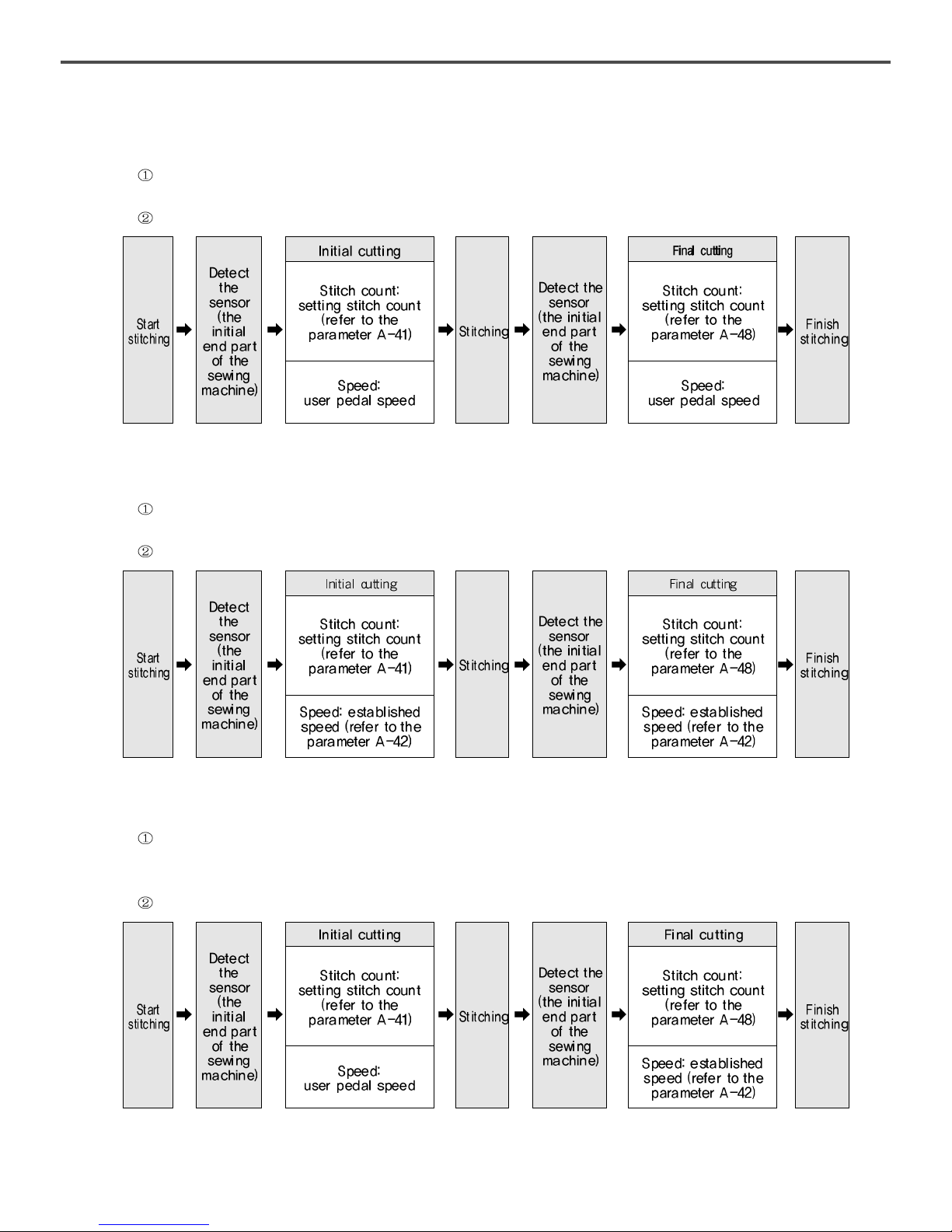
(2) Operation process of “Auto thread trimming mode 1”
feature: During pressing the pedals, the initial cutting and the final cutting is performed counting as much as the setting values
after sensor detecting.
thread trimming process
(3) Operation process of “Auto thread trimming mode 2”
feature: The sewing material is feeding as much as the stitches after detecting the sensor. When the movement stops, the initial
cutting and the final cutting start operating.
thread trimming process
(4) Operation process of “Auto thread trimming mode 3”
feature: During pressing the pedals, the value is sent to the setting value by counting the stitches after detecting the sensor.
Then the initial cutting starts working when taking your foot off the pedal. After that, the sewing material is automatically
feeding as fast as the counted values. When the feed is over, the final cutting starts operating.
thread trimming process
Page 47

47
6) THREAD TRIMMING RANGE SETTING
 Loading...