

Page 1

USER’S MANUAL
PARTS BOOK
Version 03
AC Servo Motor series
1) For at most use with easiness,
please certainly read this manual
before starting use.
2) Keep this manual in safe place for
reference when the machine
breaks down.
SSUUNNSSTTAARR MMAACCHHIINNEERRYY CCOO..,, LLTTDD..
SSUUNNSSTTAARR MMAACCHHIINNEERRYY CCOO..,, LLTTDD..
Page 2

Best Quality
Best Price
Best Service
SSUUNNSSTTAARR MMAACCHHIINNEERRYY CCOO..,, LLTTDD..
R
1.
Thank you for purchasing our product. Based on the rich expertise and
experience accumulated in industrial sewing machine production, SUNSTAR
will manufacture industrial sewing machines, which deliver more diverse
functions, high performance, powerful operation, enhanced durability, and
more sophisticated design to meet a number of user’s needs.
2. Please read this user’s manual thoroughly before using the machine. Make
sure to properly use the machine to enjoy its full performance.
3. The specifications of the machine are subject to change, aimed to enhance
product performance, without prior notice.
4.
This product is designed, manufactured, and sold as an industrial sewing
machine. It should not be used for other than industrial purpose.
Page 3
USER’S
MANUAL
Page 4

1. SAFETY INSTRUCTION............................................................................................................6
2. PRECAUTIONS BEFORE USE...............................................................................................8
3. LOCATING AND USING PARTS OF THE CONTROLLER BOX................................10
4. INSTALLATION .........................................................................................................................12
1) Attaching controller to table .................................................................................................................................12
2) Attaching pedal unit ..............................................................................................................................................12
3) Installing and adjusting knee lifter solenoid........................................................................................................13
4) Needle Bar Up/Down Stop Position Setting........................................................................................................13
5) Installing program unit ..........................................................................................................................................16
6) SunStar machine installed with program unit ....................................................................................................16
5. WIRING AND GROUNDING .................................................................................................17
1) Specification of the power plug............................................................................................................................17
2) Specification of electric current in wiring of power plug....................................................................................17
3) Names and Explanation of external connector in control box ..........................................................................18
4) Changing solenoid supply voltage (Basic setting values upon shipment: J19)...............................................18
6. CONNECTION THE EARTH WIRE OF THE SEWING MACHINE AND MOTOR..20
7. THINGS TO BE CHECKED AFTER INSTALLATION......................................................20
8. PROGRAM UNIT PART NAMES AND METHOD OF USE .........................................21
1) Program unit part names .....................................................................................................................................21
2) Program Unit Method of Use................................................................................................................................21
3) Start and End Backtack Stitch Correction Method ............................................................................................33
4) Method of Use: Inertia Tuning Function..............................................................................................................36
5) Sewing machine head open error and safety switch error...............................................................................36
6) How to Use the Edge Sensor (Fabric Edge Sensor) ........................................................................................37
7) Motor Controller Setting........................................................................................................................................41
9. SIMPLE OPERATION UNIT PART NAMES AND METHOD OF USE ......................45
1) Names of Each Part in the Simple Operation Unit............................................................................................45
2) Simple Program Unit Method of Use...................................................................................................................45
10. FORTUNA SERIES 4 FULL FUNCTION SOFTWARE METHOD OF USE ............50
1) Basic Functions of the Fortuna Series 4 Full Function Software......................................................................50
2) Fortuna Series 4 Full Function Software Specific Parameters ..........................................................................51
3) Method of Use and Explanations for Specific Items of the Parameter............................................................62
4) Thread Trimming Sequence Function Method of Use (Items no. 54, 55, 56 of Group B).............................66
11. BREAKDOWN AND TROUBLESHOOTING....................................................................74
12. HOW TO PLACE FOR CONTROLLER ...........................................................................75
13. BLOCK DIAGRAM.................................................................................................................76
※ PARTS BOOK .........................................................................................................................77
CCOONNTTEENNTTSS
Page 5
6
Be sure to read and keep in mind the following instructions before you install and use
the FORTUNA SERVO MOTOR.
1) Use and Purpose
This product is designed, manufactured, and sold as an industrial sewing machine. It should not be used for
other than industrial purpose.
2) Working Environment
Power Source
It is desirable that voltage of the power source be kept within the range of 10% of the rated voltage.
It is desirable that frequency of the power source be kept within the rage of 10% of the rated frequency.
(50/60
)
The SERVO MOTOR can be expected to work normaly only in case the foregoing things are kept.
Electromagnetic Noise
It is desirable that those equipments causing strong electromagnetic field or high frequency not use the
same electrical outlet as this on and stay away from it.
Temperature and Humidity
Keep the ambient temperature above 5 degrees and below 40 degrees Centigrade.
Never use it outdoors and avoid direct ray of light.
Keep it away from an hot object like a stove.
Keep the ambient humidity above 30% and below 95%.
Never use it near gases and explosives.
Do not use it at a spot located 1,000m or higer above sea-level.
Keep the storage temperature higher than 25 degrees below zero and lower than 55 degrees Centigrade when
not in use.
3) Installation
Follow the instruction carefully when installing it.
Be sure to start installing it after pulling the power plug off the outlet.
Fix the cable so that it may not move, and do not allow the moving parts like belts to be interfered with.(Keep
distance of at least 25mm from them.)
Be sure to have the Controller and the sewing Machine grounded.
Be sure that the voltage of power source fits the specification of the Controller before the power is on.
Be sure to use Safety Extra Low Voltage when an extra item or an accessory is fitted into the Controller.
4) Disassembly
Indisassembling it, be sure to wait at least 360 seconds before taking any action after pulling the plug off the
power source after turning it off.
When pulling off the plug from the power source, be sure to hole the plug itself instead of the wire connected
to the plug.
Page 6

7
5) Service and Maintenance
Make sure that service and maintenance are carried out by a skilled technician.
Never try to operate with the Motor and the Controller open.
When inserting a thread into or touching the machine, be sure to turn the power off and step down from the
platform.
Be sure to use standard products specified for replacement of parts.
6) Other Safety Instructions
Tack care not to let your fingers touch any moving parts including belts.
In case of remodelling or fitting of additional device, be sure to follow safety standards and do not ever try to
go ahead based on your own judgments.
Do not try to operate with the safety device removed.
Take care not to let water or coffee or something like those admitted into the Controller or the Motor.
Never drop the Controller or the Motor to the ground.
The instructions presented above are for the safer and more proper operation of the Fortuna Servo
Motor. Ignoring such instructions could cause damage to the machine or physical injury of the user.
Please follow all the instructions when operating the machine.
Page 7
8
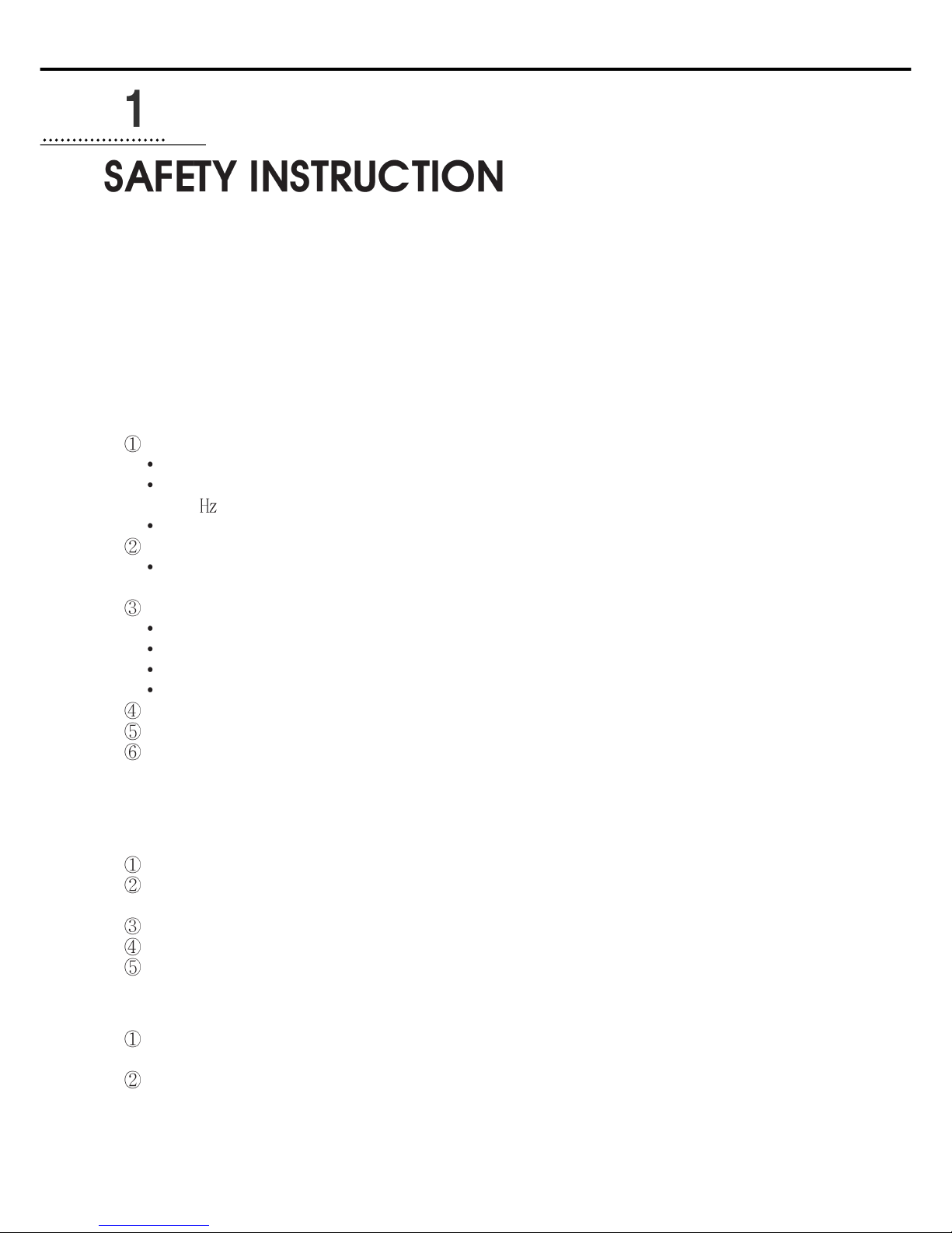
1. Do not turn on the power while stepping on the pedal. 2. Turn off the power when leaving the servomotor overnight.
3. Turn off the power when servicing the servomotor or changing
the needle.
4. Be sure to keep the servomotor securely grouned.
Motor
P/U
5. Do not connect multiple servomotor power plugs to the same
power strip.
6. Install the servomotor away from noise sources, such as highfrequency equipments and welding machines.
7. Avoid electrical shock when servicing the controller box. (Wait for 6
minutes before opening the cover after turning off the power.)
8. When an error message “Er”sppears on the digital display,
take a note of the “Er”code, and then turn on and off before
resuming operation(Contact the local dealer if “Er” message
persists on the display)
Page 8
9
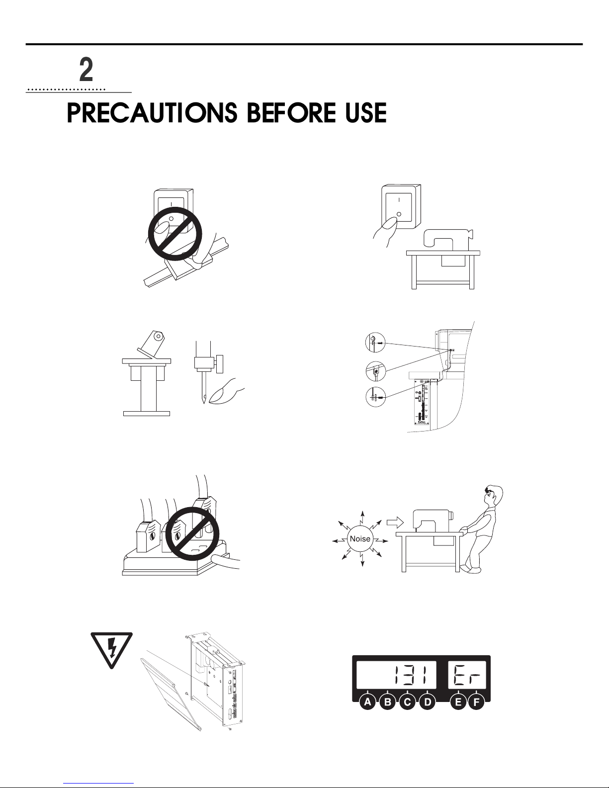
9. Clean it every two or three weeks so that no dirt or a dirty
substance may be piled up.
10. When replacing the fuse, use a standard item, opening the
cover as shown in the diagram.
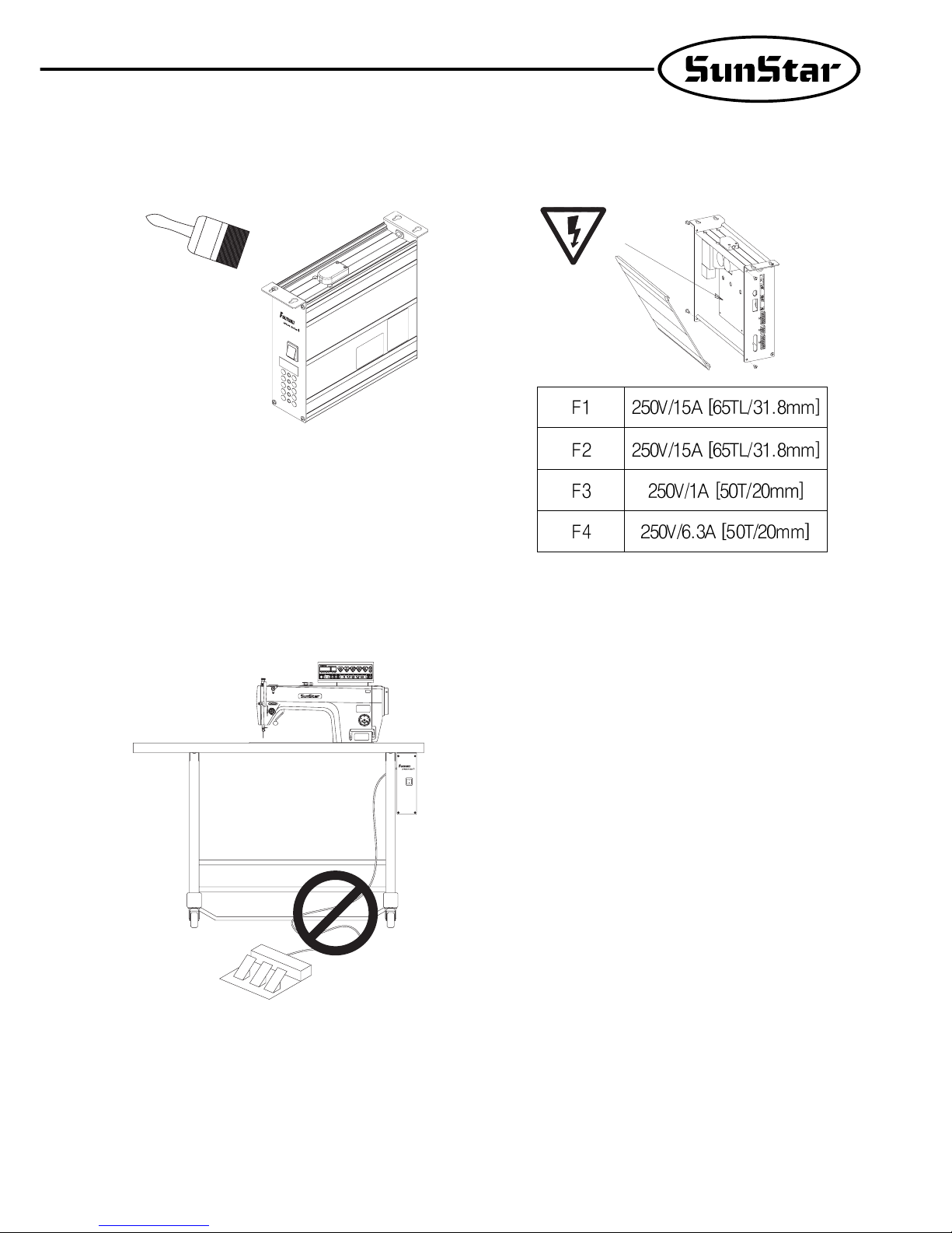
11. Make the length of the cable connected with an outside parts
like stand-up pedal as short as possible.
Page 9
10
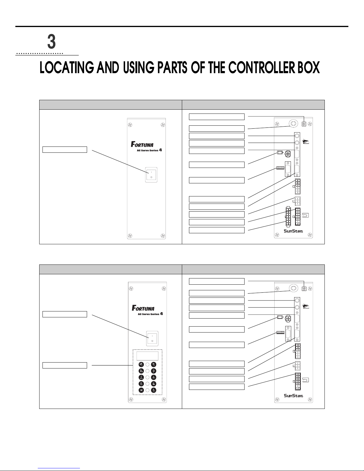
Control box back (Full Option Type)Control box front (Full Option Type)
1) Front and back of control box
AC Power switch
AC Power Input Power Cable
Control box grounding part
Option 2 Connector
Pedal Connector
Encoder Connector
Motor Power Connector
Position Detector Connector
P/U Connector
Option 1 Connector
A/B Button Connector
Solenoids Connector
Option 3
Button
A/B
Option1
Option3
S/M
Synchro
P/U
Motor
Encoder
Pedal
Option2
SUNSTAR ELECTRIC CO., LTD.
Control box back (Economic Type)Control box front (Economic Type)
AC Power switch
Simple Controller Board
AC Power Input Power Cable
Control box grounding part
Option 2 Connector
Pedal Connector
Encoder Connector
Motor Power Connector
Position Detector Connector
P/U Connector
Option 1 Connector
A/B Button Connector
Solenoids Connector
Button
A/B
Option1
S/M
Synchro
P/U
Motor
Encoder
Pedal
Option2
SUNSTAR ELECTRIC CO., LTD.
Page 10
11
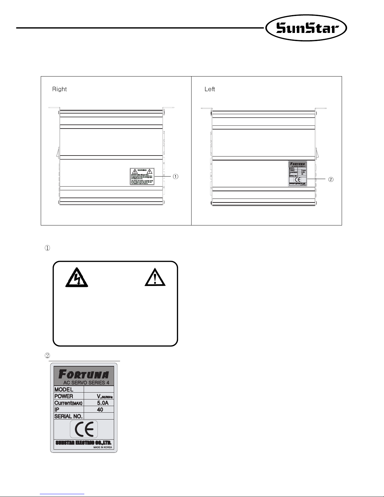
2) Control box side
Caution
Specification
Hazardous voltage will cause injury.
Be sure to wait at least 360 seconds before
opening this cover after turn off main switch and
unplug power cord.
고압 전류에 의해 감전될 수 있으므로 커버를 열 때
는 전원을 내리고 전원 플러그를 뽑고 나서 360초간
기다린 후 여십시오.
WARNING
경고
Page 11
12
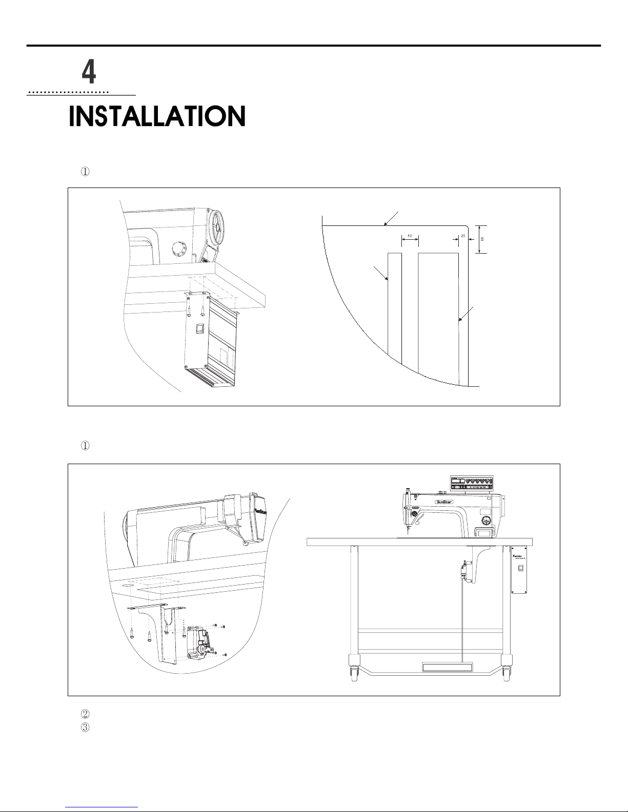
1) Attaching controller to table
2) Attaching pedal unit
As in the figure, attach pedal unit bracket to the underside of table with 15mm fixing screws.
Attach pedal unit to the fixing holes on one side of pedal unit bracket.
Pedal unit bracket should be fixed to the area where the bar linked to the pedal that is to be attached to table leg becomes vertical.
(The area where pedal unit bracket is attached depends on where the pedal is.)
As in the figure, attach control box to the lower right of the table with 15mm fixing screws.
Area where control box is
to be attached
The underside of the table, front part
Right table leg
Page 12
13
3) Installing and adjusting knee lifter solenoid
(1) For Sunstar KM-2300 Sewing Machine
Assemble Ornamental panel of knee lifter solenoid on the back
of KM-2300 body
Attach knee lifter solenoid on bracket A.
Attach the bracket A fixed on the knee lifter solenoid.
After attaching crank on the solenoid shaft, connect to the
machine.
Put cover over solenoid.
Connect grounding cable.
4) Needle Bar Up/Down Stop Position Setting
(1) Installing Position detector (KM-2300Series, SC-7300Series)
Synchronizer is attached on the machine upon shipment.
When changing and fixing synchronizer, see the manual.
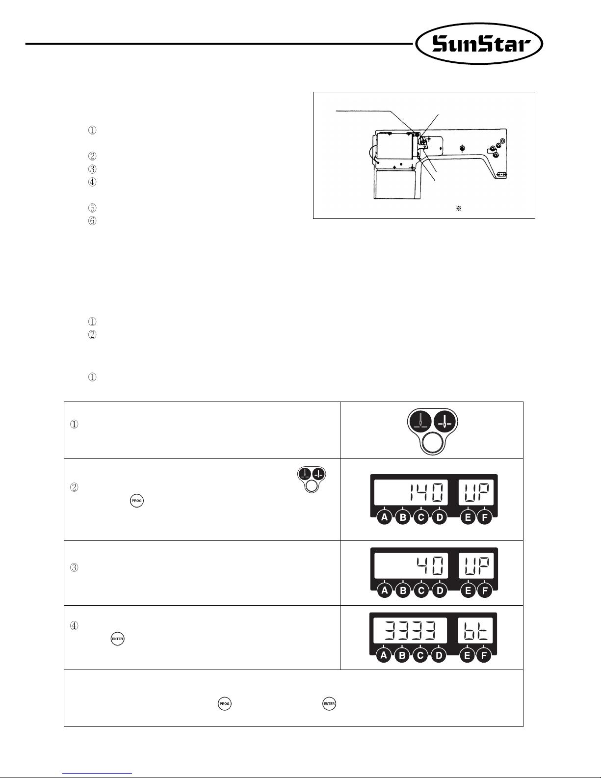
(2) Setting needle bar up-/down- stop position with using program unite (KM-2300Series, SC-7300Series)
- Fortuna Series IV allows a user set up-down stop position by using program unite without changing setting of synchronizer.
Setting needle bar up-down stop with using optional program unite.
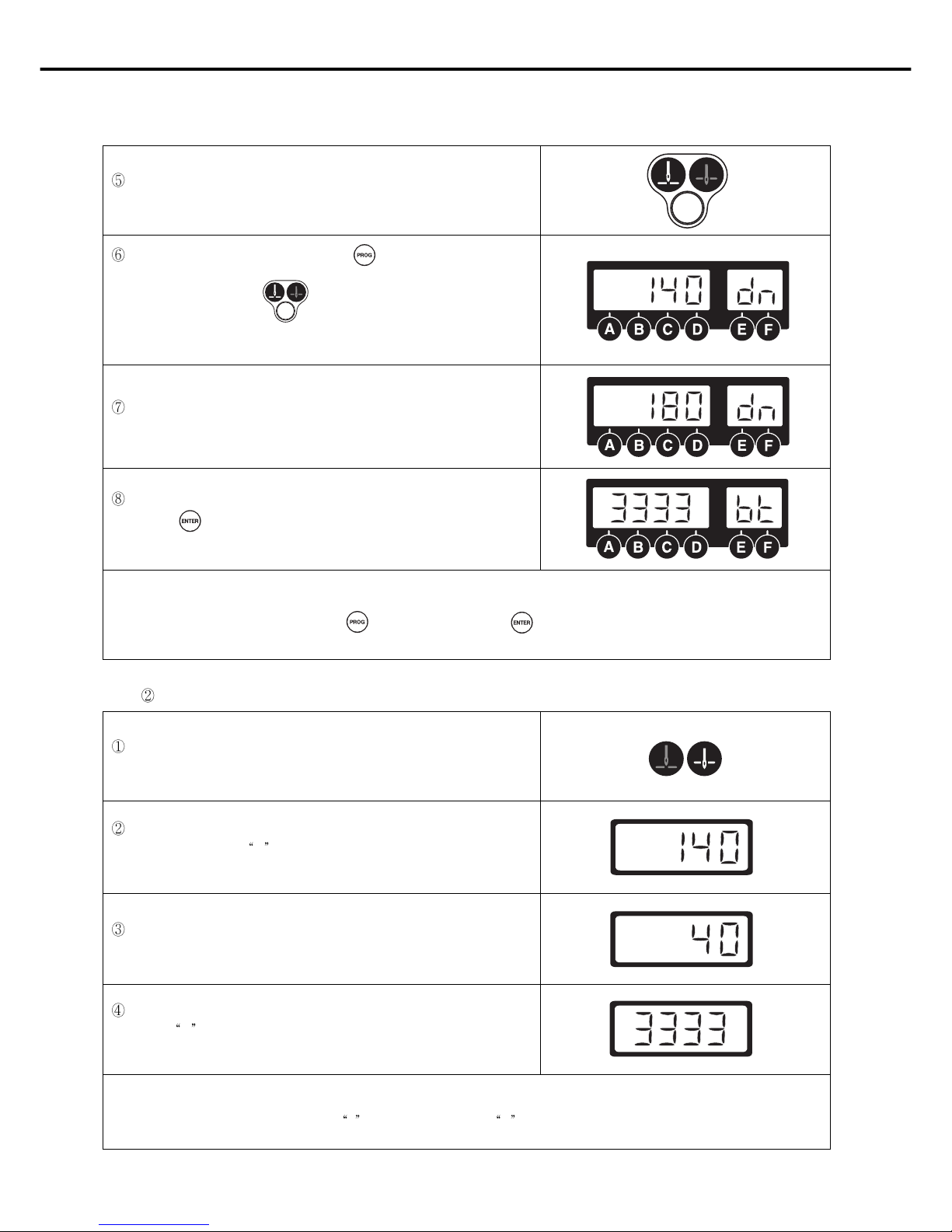
Turn on the down-stop icon lamp by pressing needle bar up-/down-stop
button on the program unit to set needle bar down-stop position.
When the up stop lamp on, press needle bar up-down stop button
with pressing the button. After that, as in the figure letter showing
information on the setting target and number pointing the current position
will blink.
Turn the pulley forward manually to move the needle bar to the desired
position. The screen displays changing position of needle bar.
When the needle bar moves to the desired position, save the position by
pressing key. Then, the screen automatically returns to the initial screen
with a buzzer.
[Caution]
Returning to the initial screen by pressing button without pressing button will not save reset values.
KM-2300 Back
Solenoid bracket A
Grounding Cable
Presser foot Solenoid Cover
Solenoid Crank
Solenoid Cover
Page 13
14
Furthermore, turn on the down-stop icon lamp by pressing needle bar up/down-stop button on the program unit to set needle bar down-stop position.
When the down-stop lamp turns on, press button while pressing needle
bar up-/down-stop button. Then, as in the figure right, the information
on what is to be set and the numbers that tell the current position of needle
bar will be shown.
Turn the pulley forward manually to move the needle bar to the desired
position. The screen displays changing position of needle bar.
When the needle bar moves to the desired position, save the position by
pressing key. Then, the screen automatically returns to the initial screen
with a buzzer.
[Caution]
Returning to the initial screen by pressing button without pressing button will not save reset values.
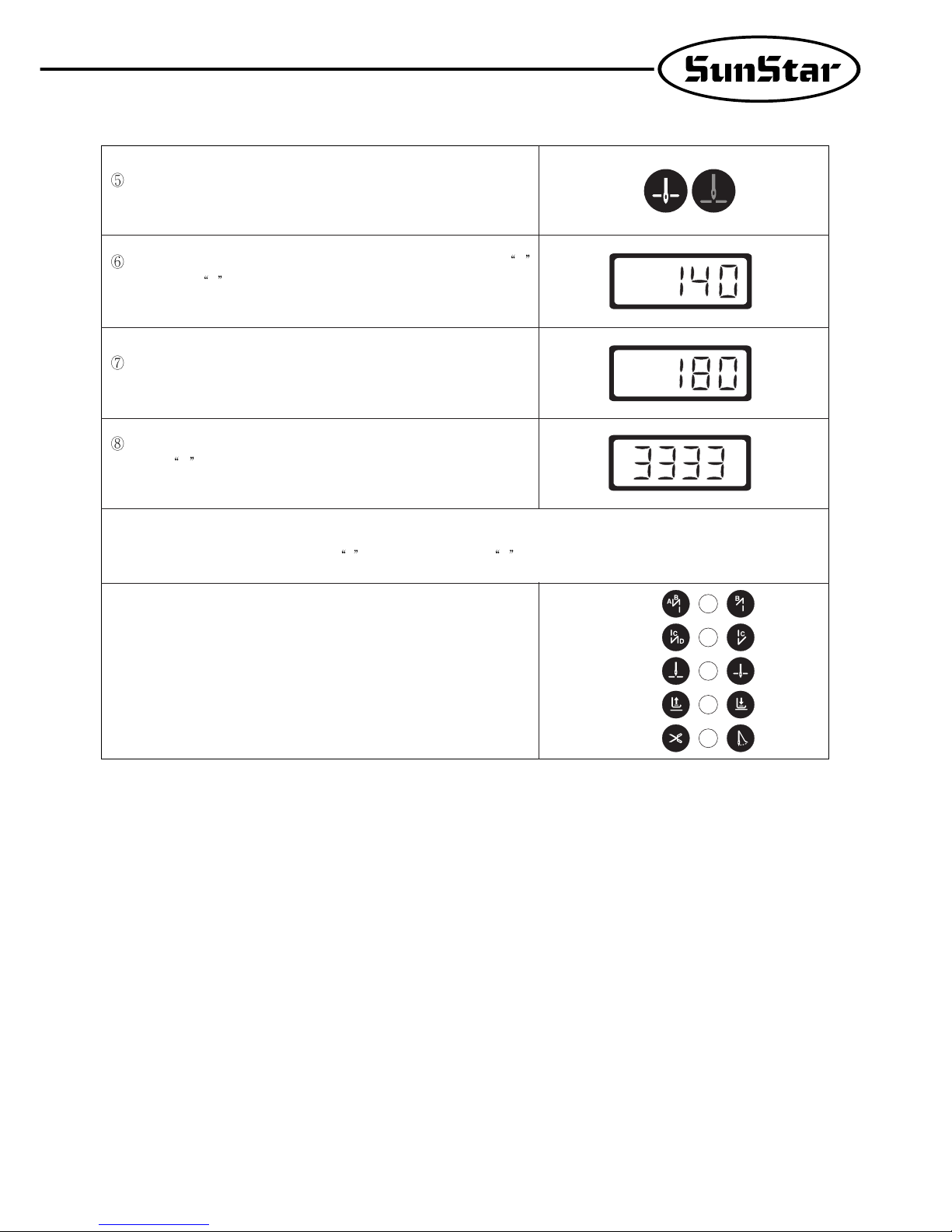
Setting needle bar up-/down-stop position by using simple controller board (front OP).
Turn on the up-stop icon lamp by pressing needle bar up-/down-stop button
on the simple controller board to set needle bar up-stop position.
When the up-stop lamp turns on, press “E” button while pressing needle bar
up-/down-stop button (
C ). Then, as in the figure right, the numbers that tell
the current position of needle bar will be displayed.
The operator turns the pulley forward manually to move the needle bar to the
desired position. The screen displays changing position of needle bar.
When the needle bar moves to the desired position, save the position by
pressing
C key. Then, the screen automatically returns to the initial screen
with a buzzer.
[Caution]
Returning to the initial screen by pressing E button without pressing C button will not save reset values.
Page 14
15
To set needle bar down stop position, press needle bar up-down stop button
of simple controller board to make on the icon lamp of needle bar up stop.
When the down stop lamp on, press needle bar up-down stop button C
with pressing E button. After that, number pointing the current needle bar
position will blink.
Turn the pulley forward manually to move the needle bar to the desired
position. The screen displays changing position of needle bar.
When the needle bar moves to the desired position, save the position by
pressing
C key. Then, the screen automatically returns to the initial screen
with a buzzer.
[Caution]
Returning to the initial screen by pressing E button without pressing C button will not save reset values.
[Caution]
The names of buttons on simple controller board are as follows.
① A Button switch( Switch for initial Reverse)
② B Button switch (Switch for end reverse)
③ C Button switch (Switch for needle bar up-down stop when the machine
stops)
④ D Button switch (Switch for automatic presser foot ascending when the
machine stops)
⑤ E Button switch (Switch for program)
①
②
③
④
⑤
Page 15

16
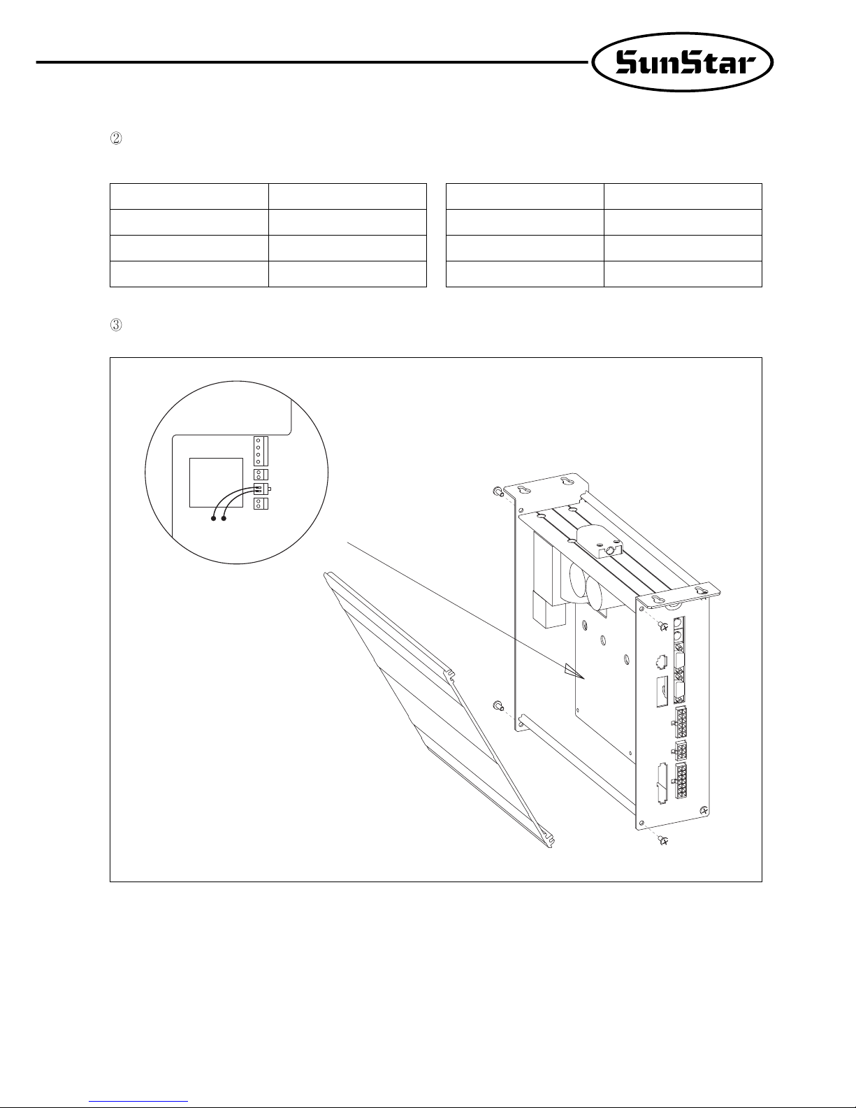
5) Installing program unit
As in the figure below, attach program unit bracket to program unit with three fixing screws. As in the figure, attach the bracket with
program unit to the head of machine firmly with two fixing screws.
6) SunStar machine installed with program unit
Page 16
17
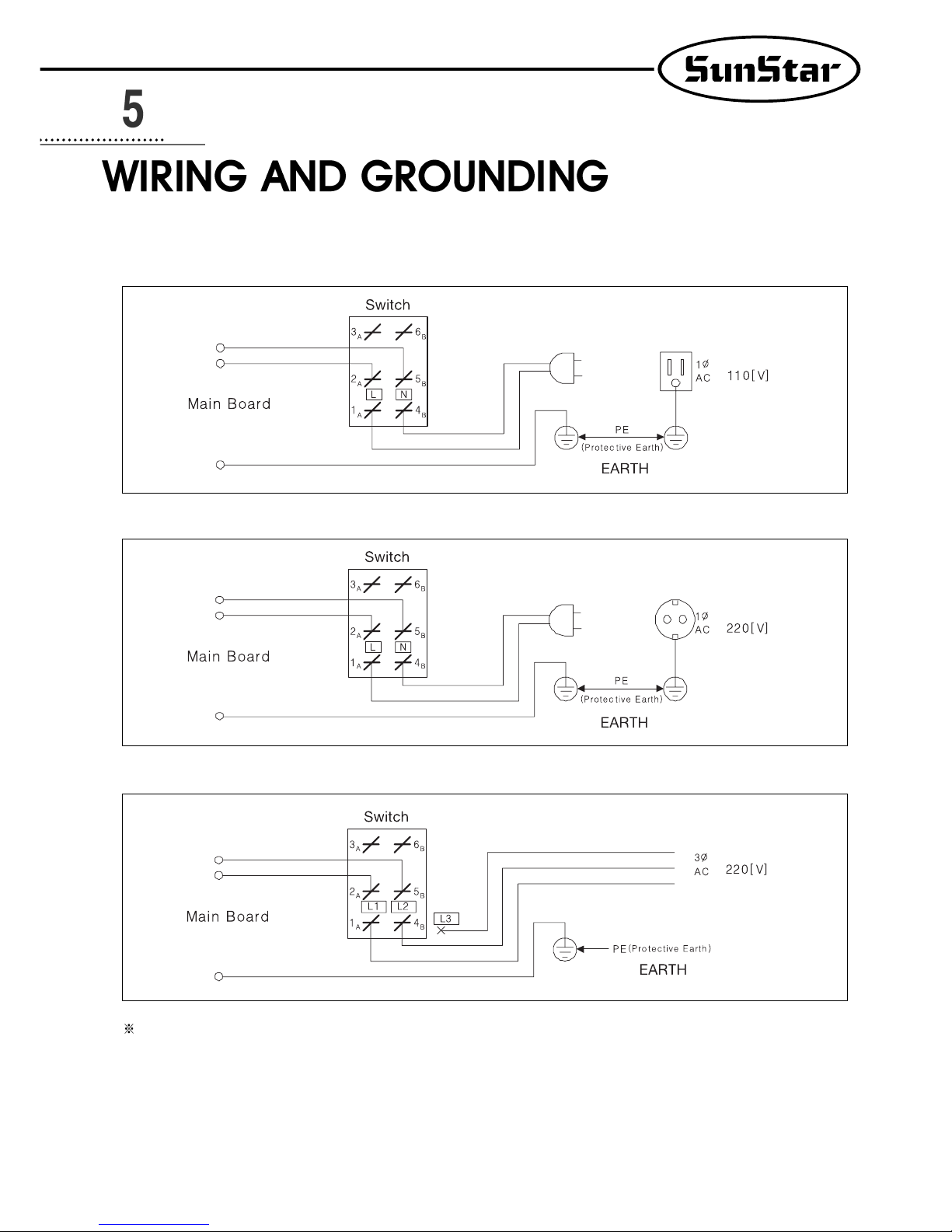
1) Specification of the power plug
(1) Single phase 100V~120V
(2) Single phase 200V~240V
(3) Three phase 200V~240V
Be sure to connect Protective Earth
2) Specification of electric current in wiring of power plug
Be sure to use wiring materials which can stand electric current of higher than 15A.
Page 17
18
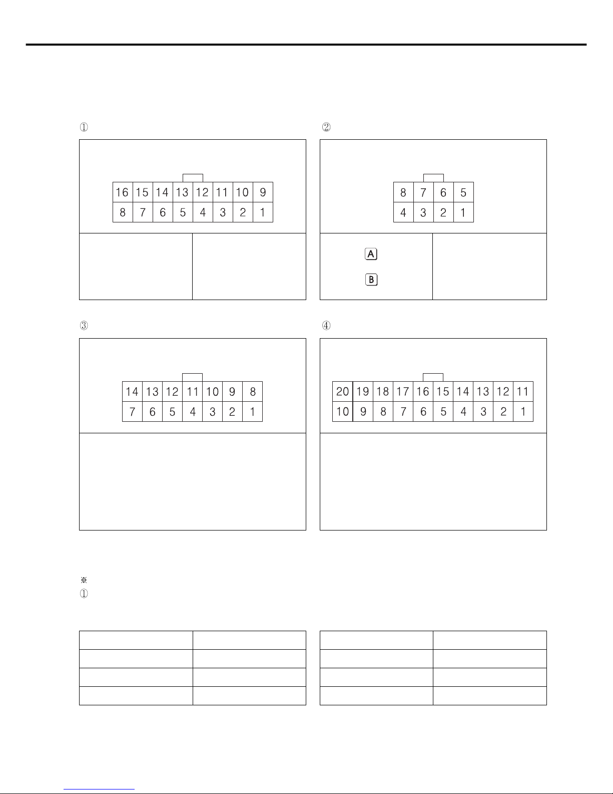
3) Names and Explanation of external connector in control box
[ Pin Number ]
[ Pin Number ] [ Pin Number ]
[ Pin Number ]
5,13: Left needle control
solenoid
6,14: Right needle control
solenoid
7,15: Thread release solenoid
8,16: Auxiliary solenoid
1, 9: Back Tack solenoid
2,10: knee lifter solenoid
3,11: Trimming solenoid
4,12: Wiper solenoid
1,5: Manual Back tack
button
2,6: Back tack Insert/Delete
Button
3,7: Knee lifter solenoid switch
4,8: Safety Switch
Solenoid Connector (5566-16P) Basic switch connector (5566-8P)
Switch and lamp connector (5566-14P) Extension connector (5566-20P)
4) Changing solenoid supply voltage (Basic setting values upon shipment: J19)
It is for a good operation of solenoid when AC input voltage changes.
Setting values of solenoid supply voltage against input voltage (input voltage 220V series)
Solenoid with the rating current of 30V Solenoid with the rating current of 24V
Input Voltage Setting Values
Less than 210V J20
210V~230V J19
More than 230V J18
Input Voltage Setting Values
Less than 180V J20
180V~190V J19
More than 190V J18
1, 2, 9, 10 : 12[V] 13 : Output 12
3~8 : GND 14 : Output 13
11, 12, 19, 20 : VCC (5[V]) 15 : Output 14
13~18: Extension Port 16 : Output 15
17 : External Input 00
18 : External Input 01
1, 2, 7 : GND 9 : 4/4
3 : Left switch LED 10 : 3/4
4 : Right switch LED 11 : 2/4
5 : Left switch 12 : 1/4
6 : Right switch 13 : Switch-CNT
8 : VCC (5[V]) 14 : Switch-HALF
Page 18
19
Setting values of supplied voltage to solenoid against input voltage (Input voltage: 110V)
Setting supplied voltage
Solenoid with rating current of 30V Solenoid with rating current of 24V
Input Voltage Setting Values
Less than 100V J20
100V~120V J19
More than 120V J18
Input Voltage Setting Values
Less than 90V J20
90V~100V J19
More than 100V J18
J22
J20
J19
J18
P5 P4
Page 19
20
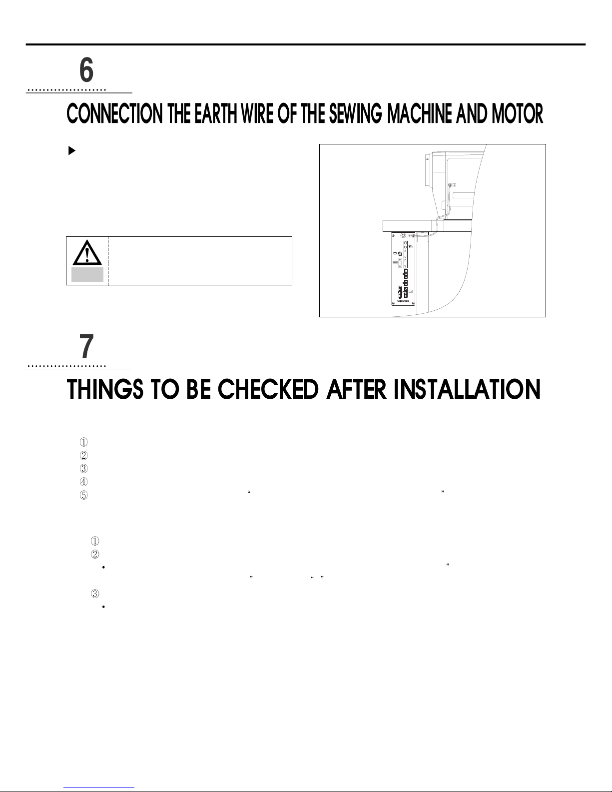
Method
As in the figure, connect grounding conductors (green or
green/yellow) that link the machine and the controller. Check if
grounding part of power is connected to the grounding conductors.
1) Before the power is on...
Make sure that the incoming voltage is in accordance with that shown in the name plate of the Control box.
Check whether the following connectors are connected.
Check to see the fixing nuts for pulley are tightly fastened.
Check whether the sewing machines are right kinds (Chain Stitch S/M, Lock Stitch S/M)
Check the rated voltage for Solenoid (Refer to How to change the electric voltage supplied for Solenoid ))
2) After the power is on...
Check whether the program unit is working.
Check the direction of rotation of the Sewing Machine.
In case the direction of rotation is not right, action shall be taken to change set it right, referring to the methods of changing the
program and the list of changing functions
(N. 65 in Group A )
Check to see whether there are abnormal heat, smell or noise nearby.
In case there are, turn the power off and call our regional office.
SUNSTAR ELECTRIC CO., LTD.
Option3
Motor
P/U
S/M
Option1
A/B
Button
Encoder
Synchro
Option2
Pedal
Caution
Failure to ground the motor can cause abnormal
operations, such as overspeed rotation or unwanted
stitching.
Page 20
21
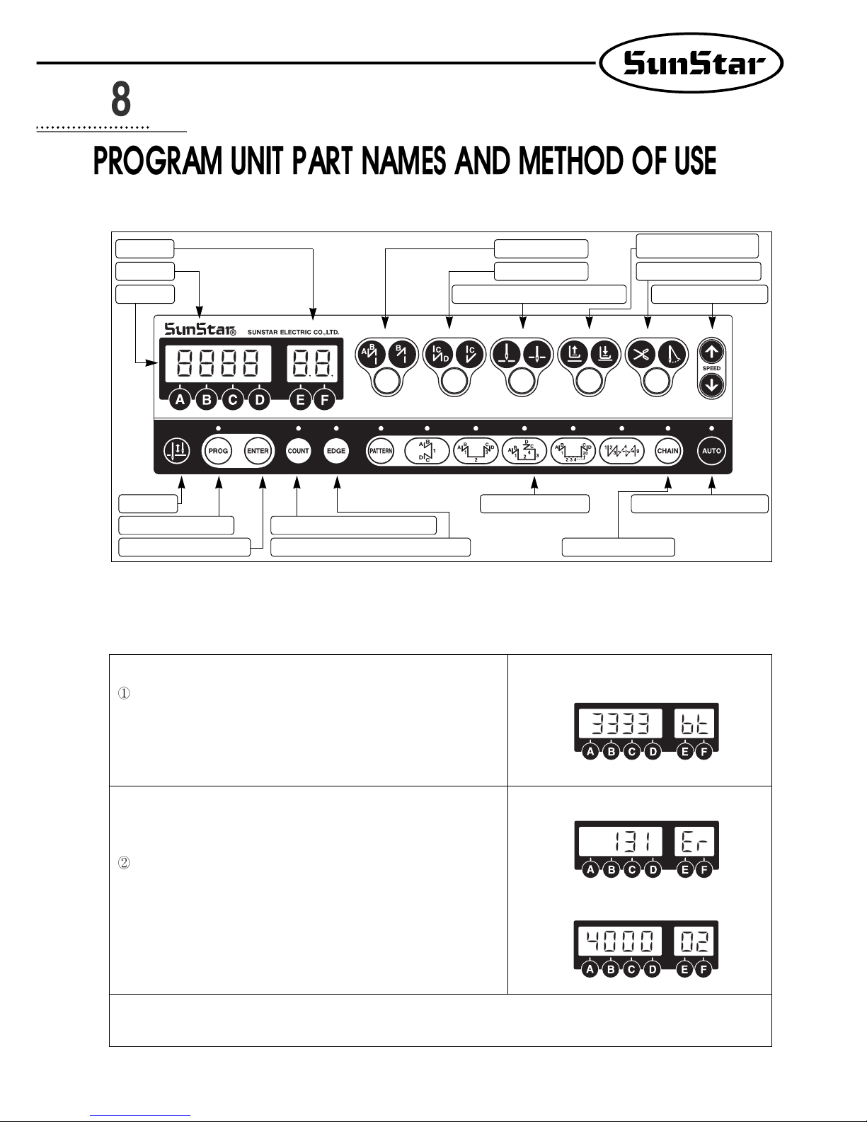
1) Program unit part names
2) Program Unit Method of Use
(1) 4-Digit Displayer and 2-Digit Displayer Functions and Method of Use
A. 4-Digit Displayer and 2-Digit Displayer Functions
When you turn the power on, you will see a screen as shown in the figure.
The 4-digit displayer shows the start and end B/T sewing and the 2-digit
displayer shows the current abbreviation for the letters or numbers shown in
the 4-digit displayer (bt: the abbreviation for back tack),
<Initializing screen>
<Example of error detection>
<Example of selection of number 2 item in Group A>
The 4-digit displayer shows the error number for each type of error
discovered and also shows the programmed value after it has been
programmed. The 2-digit displayer shows the number of the parameter
specific item's content or name which is shown in the 4-digit displayer.
[ Caution ]
The 4-digit displayer and 2-digit displayer show the current condition. Therefore the user should always check it before using the
machine.
2-Digit Displayer Start B/T Selection Button
Button to Select Presser Foot-lift
Location When Machine Stops
Sunstar Logo
End B/T Selection Button Thread-trimmer and Wiper Selection
4-Digit Displayer
Button to Select Needle Plate Location When Machine Stops
Button to Change the Sewing Speed Installation
1/2 Stitch Button
Button to Save Program Changes
Button for Counter Use after Counter Programming
Pattern Work Selection Button
Pattern Work Connecting Button
Constant Sewing Speed Selection Button
Button to use Edge Sensor Selection after Edge Sensor Programming
Button for Program Change
Page 21
22
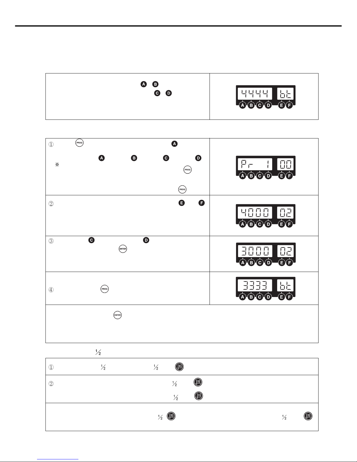
B. Method of Use: 4-Digit Displayer and 2-Digit Displayer
a. Method to change the start and end B/T stitch numbers
In order to change the start B/T stitch numbers which is programmed when you
first purchase this machine, you must use the , buttons. If you want to
change the end B/T stitch numbers, you must use the , buttons.
The program range is from 0 to 9.
(Ex: How the screen looks when changing both start and end B/T stitch
numbers to 4).
b. Method to check or change the specifics of the parameter
(2) Method of Use: Stitch Button Function
Press the button and as you press it, also press the button. Then
you can either check or change the programming items for the parameter of
group A. (A group: , B group: , C group: , D group: )
Users should turn
the machine off to select B, C, or D group. While pressing the button,
turn the power switch on. The screen will be changed to the initial screen
after showing the "PrEn" message. Then, the users can select B, C, or D
group by pressing B, C, or D button while holding program button.
You can move to the parameter item you want with the and
buttons. The parameter item number will appear in the 2-digit displayer and
the wanted value will appear in the 4-digit displayer.
(Ex) Screen showing the maximum speed limit preset in the item 2 of A group)
After using the (increase) button and (decrease) button to choose
the value you want, press the (Enter) button and save the value you
chose. (Ex: Reducing the maximum sewing speed limit from 4000RPM to
3000RPM).
After saving, press the button and go back to the initial screen.
[ Caution ]
Be aware that if you don't press after changing the programmed value for the parameter item, the value will not be saved.
When the B, C, or D group selection is completed, users should turn off the machine first and restart to secure the selected group.
If the user changes the programmed value from the parameter specifics carelessly, the user may cause break down or physical damage to
the machine. The user must therefore be well-trained before changing the parameter group.
When necessary, make stitches by pressing the stitch ( ) button.
When the needle plate makes a down stop, shortly press the stitch ( ) button once and the needle plate will make an up stop.
And when the needle plate makes an up stop, shortly press the
stitch ( ) button once and the needle plate will make a down stop.
[ Caution ]
Be aware that if you are continuously pressing the ( ) button, the machine will keep on moving at the stitch ( )
speed.
Page 22

23
(3) Method of Use: Start B/T Button
This button is used when the user wants to prevent threads from loosening at the end of the sewing work. If the user presses this button
in sequence, the location on the lights will change. This button offers the following three functions.
Using the A, B buttons in the 4-digit displayer, the user can program the B/T number of stitches he/she wants.
When sewing starts, B/T
sewing does not operate.
[ Caution ]
Be aware that if the start B/T stitch is set to '0' in the 4-digit displayer, the start B/T sewing is impossible.
When sewing starts, B/T
sewing is operated with
the
button.
When sewing starts, B/T
sewing is operated with
the
button.
(4) Method of use: End B/T Button
This button is used when the user wants to prevent threads from loosening at the end of the sewing work. If the user presses this button
in sequence, the location on the lights will change. This button offers the following three functions.
Using the C, D buttons in the 4-digit displayer, the user can program the B/T number of stitches he wants.
When sewing ends, B/T
sewing does not operate.
[ Caution ]
Be aware that if the end B/T stitch is set to '0' in the 4-digit displayer, the start B/T sewing is impossible.
When sewing ends, B/T
sewing can be operated
with the
button.
When sewing ends, B/T
sewing can be operated
with the
button.
(5) Method of Use: The Needle Plate Position Selection Button When the Sewing Machine Stops
When the user turns the power on, one of the up stop or down stop lights in the program unit panel needle plate is always left on. The
user can change the stop location by pressing the button.
When machine stops while sewing, the
needle plate makes an up stop.
When machine stops while sewing, the
needle plate makes a down stop.
Page 23
24
(6) Method of Use: The Presser Foot-lift Location Selection Button When the Sewing Machine Stops
When the user turns the power on, one of the up stop or down stop lights in the program unit panel pressser foot-lift is always left on.
The user can change the stop location by pressing the button.
[ Caution ]
If the user uses the automatic up stop function of the presser foot-lift when the sewing machine stops while sewing, it may cause
damage to it because it has been left up for an unnecessarily long time. Be aware that to prevent the foot-presser solenoid from
being damaged, it is programmed to automatically come down when a certain amount of time passes.
When the machine stops while sewing, the
presser foot-lift stops at the top.
When the machine stops while sewing, the
presser foot-lift stops at the bottom.
(7) Method of Use: Automatic Thread Trimmer and Wiper Selection Buttons
These buttons offer the function of automatic trimming and wiping after sewing. By pressing these buttons in sequence, the user can use
one of the following three functions. The light shows the function that is currently being used.
Automatic trimmer and
wiper do not operate
Only automatic trimmer
function is operate
Both automatic trimmer and
wiper operate
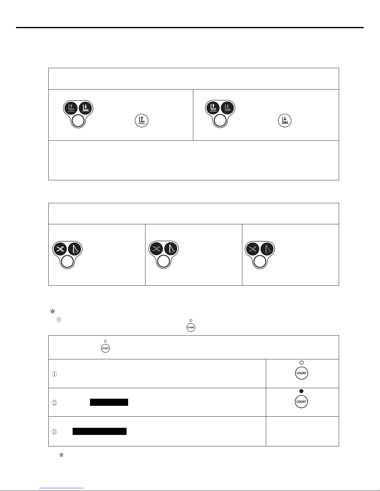
(8) How to use product counter and bobbin counter
Product and bobbin counters are functionalities available for Fortuna Series IV option type
To use the counter function, set the detailed functions under parameter B-Group.
When product counter and bobbin counter are not used
When product is set
counter function
When is set
bobbin counter function
Repeatedly press the ( ) button in the program unit to change the status of the lamp and functions as below.
How to set product counter and bobbin counter
A. Set/clear product counter and bobbin counter using the button in the program unit
<When the lamp is off>
<When the lamp is on>
<When the lamp is flashing>
Page 24
25
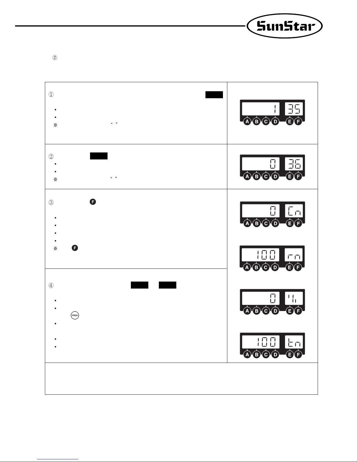
How to use detailed functions of product counter and bobbin counter
A. How to use the detailed functions of product counter
To use the counter function, set the detailed functions beforehand.
Set the parameter to select the type of product counter
1: Up counter
0: Down Counter
The default value is set at 1 .
B-36
Press the counter button to set the counter function. Press the button to check and
set the detailed data of the counter.
Cn: The current counter amount
rn: The remaining amount
%: The progress
tn: Total target amount (Default: 100)
Press button repeatedly to see the above detailed data in order. The user may
set up the current counter amount (Cn) and the total target amount (tn) as desired.
After the total target amount is set, use and to set the movements.
<Set value of B-37>
0: When work is finished, the buzzer will go off and sewing may begin
1: When work is finished, the buzzer will go off and sewing may begin only when
the button is pressed
2: When work is finished, the buzzer will not go off and sewing may begin
< Set value of B-38>
0: No returning to automatic initial value when counting is complete
1: Returning to automatic initial value when counting is complete
B-38
B-37
To use the product counter function, first set the value of the parameter
(group B, item 35) as desired.
0: Set the external counter switch on
1: Set the automatic counter on after trimming
As the default value is set 0 , the counter will not run if there is no external counter
switch.
B-35
<The current amount>
<The remaining amount>
<The progress>
<Total target amount>
[ Caution ]
When B-38 is set at “0”, the value will keep on going up/down even when counting is complete. The user will need to re-set the
value of Cn to restart.
Page 25
26
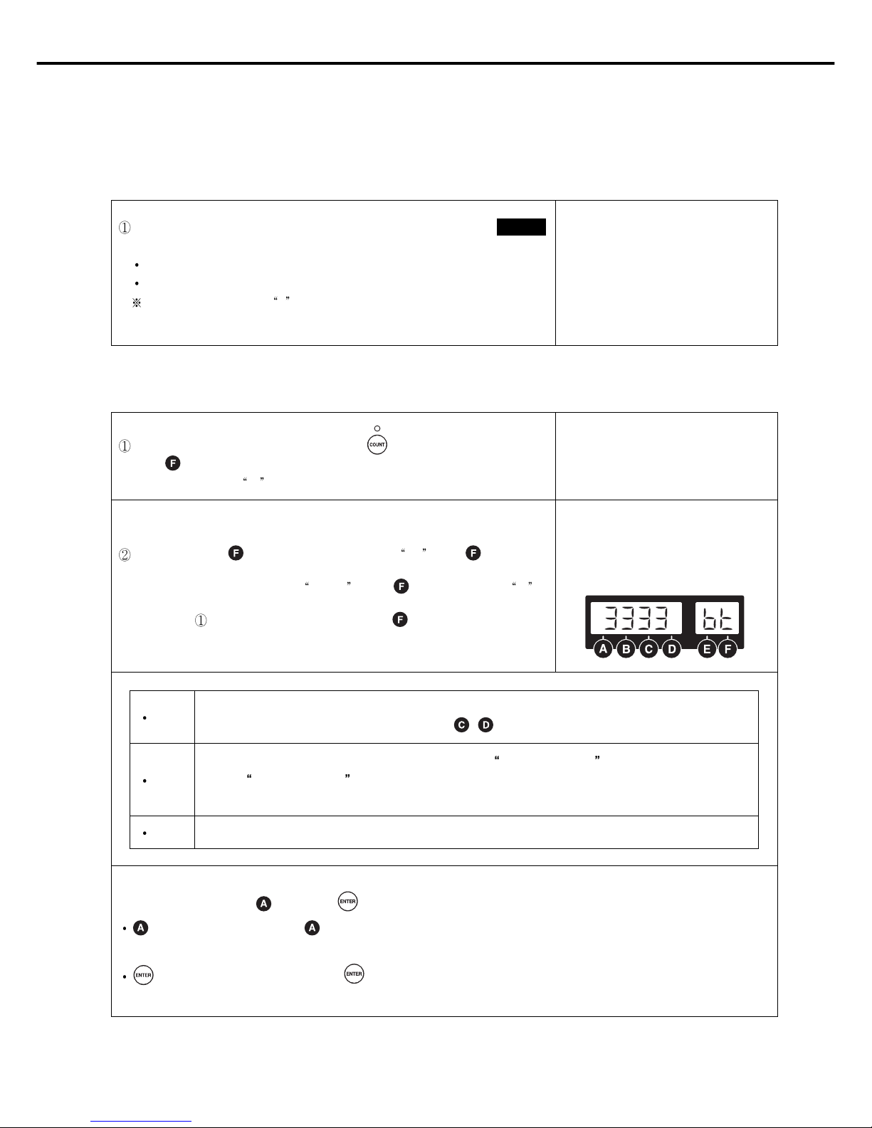
B. How to use the detailed functions of bobbin counter
Bobbin counter is designed to check the remaining amount of the lower thread.
a. To use the counter, set detailed functions beforehand.
b. Detailed functions of bobbin counter
To use the bobbin counter function, first set the value of the parameter
(Group B, item 39).
0: Bobbin counter function not used
1: Bobbin counter function used
The default value is set at 0 . At this point, the bobbin counter will not start even
when the counter button in the program unit is set at bobbin counter function.
B-39
Select the bobbin counter function by pressing button to get the lamp flashing.
Press button and the display will change
as shown in the right.
bc stands for bobbin counter.
At this point, press button to change the display to UP . Press button again
to go back to the initial display of
3333 bt . Press again to change to bc as
explained in
. The display will change by pressing button.
[bc]
[UP]
[bt]
Bobbin counter. The value will go down from the set value during sewing.
(Initial value: 0, Set range: 0~9999, How to set: use / button)
This value will go up in proportion to the reduction ratio of bc (bobbin counter) Use this value to get the initial
value of
bc (bobbin counter)
(Initial value: 0, Set range: 0~9999, Set manual increase/decrease function with C/D button)
Back-tack function that is shown in the initial display
[ Caution ]
※Pay caution when using button and button, designed to perform special functions for bobbin counter.
button (Clear/Preset) : Press button when “bc”is shown on the display. Then the buzzer will go off and the current
value will be stored as indicated, and will change to the value of bobbin counter.
button (Store counter value) : Press button when “bc”or “UP”is shown on the display. The current indicated value
will be stored as value of bobbin counter.
Page 26
27
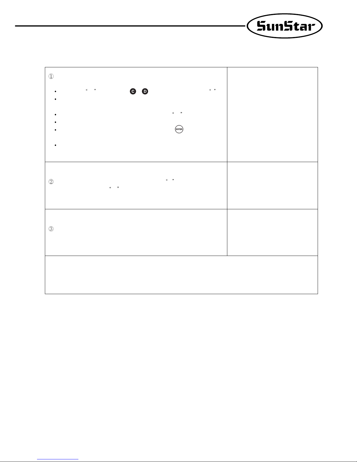
b. Detailed functions of bobbin counter
When you start new sewing work, you must re-set the value of bobbin counter. Refer
to the following if you do not know your re-set value.
First move to UP display and use , button to change the value to 0 .
Replace old lower thread with the new one. The amount of the lower thread must be
consistent.
Begin sewing. The more you sew, the higher the value of UP will be.
Continue sewing until you run out of the lower thread.
When there is no lower thread left during sewing, press button to store the
counted value.
Before saving, subtract some 10~20 from the value in order to reflect the counted
value after the lower thread ran out.
When the bobbin counter setting is complete, move to bc display. Then, you will
see the value you stored on
UP display.
The value of “bc (bobbin count)” decreases gradually when sewing begins after
completing set-up.
[ Caution ]
※ Before using the bobbin counter function, move to “bc”display or initial display. If you start working from “UP”display, the
value of counter will go up.
Page 27

28
c. When bobbin counter is complete
Replace old lower thread with the new one. Start sewing and the value of bc (Bobbin
counter)
will go down gradually.
Take note that the buzzer will go off when the value goes down below 20. This is to
warn that there is little lower thread left.
Continue sewing till the value of bobbin counter hits 0. Then sewing will stop,
buzzer will go off, and the display will start to flash.
When sewing stops after counting is complete, use the following method to return.
Press to change to the automatically stored value of bc.
(AUTO CLEAR/PRESET)
[ Caution ]
※ To use the bobbin counter function, first set B-Group 39 to “1.”
※
Use button to change the display to set/clear the value of bobbin counter during sewing.
※
button is used to set the value of bobbin counter on “bc” display or to return to the default value. Press A button to clear
the current value and recall the stored counter value.
※
Wind the lower thread with consistency to ensure the proper use of bobbin counter functions. Counter functions may work
differently depending on lower thread and sewing conditions.
Page 28

29
(9) Method of Use: Sewing Material Edge Sensor Selection Button
A. Method of Use: Edge Sensor Function
After programming the edge sensing function in the sewing material from the parameter
specific items, press the button. If the light goes on, you can start using the edje sensor
function.
B. Method of Use of Sewing Material Edge Sensor's Specific Functions
The sewing material edge sensor selection button has a function that enables the machine to stop when it senses the end of a sewing
material. If you want to operate a particular function, you must program a few specific items.
User must change item programmed value according to the characteristic of
the installed sensor.
0: When edge sensing, 5V output (Active High) should be the initial value
1: When edge sensing, 0V output (Active Low)
A-40
After sensing, you can set up the movement to item , .
<Item A-41: the number of stitches it will sew after it senses the edge>
0~225: after sensing, the machine will sew as many stitches as it has been
programmed to sew.
<Item A-42: the sewing speed after it senses the edge of material>
20~2000RPM: this item sets up the speed of the stitches set to be sewn after it senses
the edge.
A-42A-41
After sensing the edge of sewing material and the machine has sewn the number of
stitches at the programmed speed, the user needs to select item A-43 to change the
operation.
0:to stop after sewing the programmed stitch numbers.
1:to operate automatic thread trimming function after sewing the programmed
stitch numbers.
Page 29

30
(10) Method of Use: Pattern Work Selection Button
A. Method to Set Up the Pattern Work Function
This function is used when you need to continuously work on a sewing material. If the
light goes on after pressing the button, you can use the pattern sewing function.
B. Method of Use of Pattern Sewing Specific Functions
Cautionary words when using the pattern function
Before using the pattern function, finish the trimming work and turn on the pattern switch light.
If the user presses the pattern switch twice when he/she is not using the pattern function, the light will go off and he/she will be
able to go back to normal sewing. However, if the pattern mode has not been completely finished, the pattern light will not go off.
The pattern function sewing speed will be the programmed speed.
The value set in each pattern mode is not erased when the power is turned off. Therefore, if you want to use the same pattern
again, press the same mode again to use it. However, if the program is initialized, all the formerly programmed information will
be erased and the user must reset the information again.
Method of use: function
first press the button and select the pattern sewing function.
Select the pattern you want and the light will go on the pattern you selected.
If you press the button, the screen will change and you can use the stitches of
each side of the pattern you chose to program the value.
< Method to program the value of each pattern side >
Method by using the , buttons
-Inputting directly the number of stitch the user wants by using the buttons C and D.
This method is used when the user already knows the length of the stitches he/she
is choosing.
Method using the pedal movement
-This is a function used when the user does not know the stitch length and sews
directly to check the number of stitches for the pattern he/she wishes to program. If
the user presses on the pedal after the programming screen comes on, the pedal can
program the number of stitches by using the accelerating and decelerating
characteristics through the pedal's sensors. The standard for choosing the number
of stitches here is slower than the normal sewing speed and the programmed
pattern sewing speed.
Method using the A button and 1/2 stitch button
-This function is used when the user needs to make small adjustments at the end of
the pattern work. It allows the user to check and program the pattern length while
he/she sews at a slow speed or sews half stitches.
P:When the AUTO light is off, the machine
stops when the pedal is released while
sewing.
A:When the AUTO light is on, the machine
will finish sewing the pattern section
even if user releases pedal while
sewing.
<Screen showing thef programming of
stitch numbers for each side>
After programming is finished, press the button and save the set up value. Then press the
button. After the stitch numbers of each side disappear from the screen, you can start
sewing with the programmed value in the pattern sewing function.
The pattern sewing speed is constant because it sews at a programmed speed not by the
acceleration or deceleration of the pedal. If you press the pedal after pressing the button and
see the light blink, sewing will continue until it is finished even if you release the pedal.
[ Caution ]
After setting each side of the stitches, the user must press the button to save the programmed value.
When the pattern has more than one side, the pattern work only operates for the number of stitches programmed for each side.
Page 30

31
Specific items of each pattern
A convenient pattern for straight sewing at constant speed for a definite length. The
sides can be set from 0 to 999 stitches.
A convenient pattern for repetitive 3-sided sewing. Each side can be set from 0 to 999
stitches.
A convenient pattern for 4-sided sewing. Each side can be set from 0 to 999 stitches.
(Used often in square sewing)
A convenient pattern when forward/backward sewing is needed continually.
forward/backward sewing is possible 9 times. Also each side can be set from 0 to 999
stitches.
(This pattern is used for continuous work on back tags of leather belt rings).
A convenient pattern when the user wants to make many-sided patterns. The user can
make patterns of up to 20 sides. Each side can be set from 0~999 stitches.
Method of Use:Chain function (pattern linking function)
First press the button and select the pattern sewing function
Next, press the button.
If you press the button, the screen will change as the figure shows on the right.
You can change the number of chains with buttons , .
If you want to program the number of chains in the pattern you want, use buttons
and, to go to the item you want and press the pattern button.
After programming the chain numbers as explained above, press the button and
the change of value will be saved. Then press the button to come out from the
chain programming screen.
If you operate the programmed sewing work, the pattern with the blinking light is the
current work being done and the pattern with the light on continuously is the next
programmed pattern.
[Caution]
After programming the chain function and pressing the button, the set up value is saved.
If you change the pattern program while sewing, it will sew with the new programmed pattern.
If the last chain pattern is finished, it will automatically go to the first sewing pattern.
If the user presses the when using the pattern sewing function, the light will go on and the machine will automatically sew
the programmed pattern section even if the user releases the pedal.
Page 31

32
(11) Method of Use: Constant Speed Sewing (AUTO) Selection Button
(12) Method of Use: Sewing Speed Program Changing Button
A. Method to Check Sewing Speed
This button is used to choose the sewing speed. It offers two functions according to where the light turns on.
[ Caution ]
This button works in a different way when using the pattern function. Please refer to section 10).
When the light is blinking
- If the user presses on the pedal, the
machine will sew at the programmed
sewing speed.
When the light is off
- The machine will sew according to the
amount of pressure given to the pedal
by the user.
If you want to check the current programmed sewing speed, you must press the
button. If you briefly press the button button once, the screen shown on your
right will appear briefly and then return to the initial screen.
The speed on the screen is the limit of the maximum sewing speed.
[ Caution ]
The maximum speed and minimum speed limits can be changed by changing the parameter's specific items.
B. Sewing Speed Changing Method
When you want to change the sewing speed, you can see the screen that shows the
current sewing speed by pressing the button or button.
If you see the current speed on the screen, you can change the speed by using the
and button before going back to the initial screen.
When you press the buttons twice in sequence: The sewing speed increases/decreases
by 40RPM.
When you keep pressing the button: The sewing speed increases/decreases rapidly.
[ Caution ]
-Be aware that if you don't press the or button, the screen will automatically go back to the initial screen.
-The maximum speed and minimum speed limits can be changed by changing the parameter's specific items.
Page 32

33
3) Start and End Backtack Stitch Correction Method
※ Since backtack stitches may vary according to the type of sewing machine, use the following stitch correction method.
※ To adjust the stitch fast and clean, users should check the stitch condition before commencing the correction.
① Classification according to backtack sewing condition
※ The backtack sewing condition can be classified as follows (When A: 3 stitches, B: 3 stitches, C: 3 stitches, D: 3 stitches)
A. When one more or less stitch than the set stitch number is sewn
B. When one more or one less stitch is sewn than the programmed stitch number
[Caution]
The figures above show each representative sewing condition. And there may be some differences according to the conditions of
the sewing machine and it is normal that two types of conditions occur at the same time.
Classification
Sewing condition where few backtack
Correct backtack sewing condition
Sewing condition where more
stitches are sewn backtack stitches are sewn
When sides A and B each have When sides A and B each have 3 When sides A and B each have
one less stitch sewn stitches correctly sewn one more stitch sewn
When sides C and D each have When sides C and D each have 3 When sides C and D each have
one less stitch sewn stitches correctly sewn one more stitch sewn
Start backtack
Sewing condition
End backtack
Sewing condition
Classification
B/T condition where the stitch length
Correct B/T sewing condition
comes out shorter
When the length of the last three stitches When sides A and B have 3 When sides A and B each have 3 stitches
in sides A and B have been sewn short. stitches correctly sewn.
and a half stitch (or less than one stitch) sewn
When the length of the first stitch in sides When the sides of C and D have 3 stitches
When the sides of C and D each have 3 stitches
C and D have been sewn short. correctly sewn
and a half stitch (or less than one stitch) sewn.
Start backtack
Sewing condition
End backtack
Sewing condition
Page 33

34
② Start/End B/T stitch number correction method
The method to correct B/T stitch numbers may differ according to the user. However it is basically done in the following order.
A. When the machine sews one less or one more stitch than the programmed number of stitches.
[Caution]
The stitch number correction value program range is between -6 stitches to 6 stitches. You cannot see the currently applied
correction value on the initial screen. If you want to see the currently applied correction value, press the button and then
the button and either check the programmed value of each side or check items 30(side A's
correction value), 31(side B's correction value), 32(side C's correction value) and 33(side D's correction value) from Group B of
the parameter.
If each side's corrected value has been corrected to the minimum or maximum value limit (between -6 stitches to 6 stitches)
and the sewing condition is still not correct, reduce the B/T sewing speed.
Generally, you can correct in the manner mentioned above when there is more than one stitch difference. And you can correct
when there is less than one stitch difference with the item mentioned in the next page.
ⓐ First, fully check the B/T sewing condition
: Commence sewing and check the current sewing condition. Refer to the figure above.
The example above is an explanation of when one B/T stitch number comes less than one
When there is more than one stitch is added or missing, you can correct the stitch number as explained above.
<Initial screen>
ⓑ If you have checked the sewing condition, first correct the stitch number that differs by
one or more stitches to the programmed stitch number.
Correction method for stitch numbers with more than one stitch difference
Program range: -6 stitches ~ 6 stitches
Program unit: 1 stitch
Method to apply correct stitch number (program using buttons A, B, C and D).
After programming, press the and buttons simultaneously.
Ex) When there is one less Start or End B/T stitch sewn.
Side A programmed value 3(programmed stitch number) + (3-actual stitch number sewn on side A)
Side B programmed value 3(programmed stitch number) + (3-actual stitch number sewn on side B)
Side C programmed value 3(programmed stitch number) + (3-actual stitch number sewn on side C)
Side D programmed value 3(programmed stitch number) + (3-actual stitch number sewn on side D)
a In the initial screen use buttons , , , to change it from “3 3 3 3”to “4 4 4 4.”
b After programming it to “4 4 4 4”press the button. Then press the 1/2 stitch button.
You will see the letters “bt-C”and the buzzer will ring three times and the screen will automatically
return to the initial screen.
c The changed initial screen will continue to display the wanted B/T programmed value of “3 3 3 3.”
d Recommence sewing and check the corrected stitch number
e If the corrected sewing condition continues to show more than one stitch difference, repeat steps
(a~d) and make corrections.
Page 34

35
B. When the machine sews less than a stitch more or less than the one programmed.
ⓐ If there are still problems with the B/T sewing condition even after correcting the stitch
numbers for more than one stitch difference based on item "A," refer to figure ①-B and
check the sewing condition again.
<Initial screen>
<When the stitch length comes out short>
<When the stitch length is less than one stitch>
ⓑ Look at the sewing condition and make the correction as follows:
Program range for making stitch corrections for less than one stitch:(Prog+Auto)
-6 stitches ~ 6 stitches
Program unit: 0.05 stitches (Corrections are done by dividing one stitch into 20 parts).
Initial program: A(00.30), B(00.30), C(00.40), D(00.40)
Correct stitch number application method (use C and D buttons for programming).
When the stitch length comes out short(the third stitch of sides A and B/ the 1st stitch of sides C and D)
<When the stitch comes out less than one stitch longer> (the last stitch of sides A and
B/ and the first stitch of sides C and D)
[Caution] • The shadowed part is the currently saved correct value.
• After programming, press the button and save the programmed value.
Ex) When the Start/End B/T stitch length is shorter than the programmed stitch length (by around half a stitch).
Side A program value (Currently programmed corrected value)
+ (01.00-the length of the 3rd stitch sewn in side A)
Side B program value (Currently programmed corrected value)
+ (01.00-the length of the 3rd stitch sewn in side B)
Side C program value (Currently programmed corrected value)
+ (01.00-the length of the 1st stitch sewn in side C)
Side D program value (Currently programmed corrected value)
+ (01.00-the length of the 1st stitch sewn in side D)
a. In the initial screen, press the button and then also press the button.
b. The screen will then go to the stitch number correction screen. Using the , buttons
you can change the length of each side (A,B,C and D) in this screen.
c. If you have finished programming the new correction values to sidesA, B, C and D, press the
button and save the corrected value. If you press the button, you will return to the
initial screen. (A:00.30, B:00.30, C:00.40, D:00.40) → (A:00.50, B:00.50, C:00.75, D:00.75)
d. Commence sewing and check the B/T sewing condition.
e. If the corrected sewing condition still shows differences between the programmed value, the
repeat steps (a~d) and continue correction.
Side A program value (currently programmed correction value)
- the length of the extra part of the stitch sewn on side A
Side B program value (currently programmed correction value)
- the length of the extra part of the stitch sewn on side B
Side C program value (currently programmed correction value)
- the length of the extra part of the stitch sewn on side C
Side D program value (currently programmed correction value)
- the length of the extra part of the stitch sewn on side D
[Caution]
If each side's corrected value has been corrected to the minimum or maximum value limit (between -6 stitches to 6 stitches)
and the sewing condition is still not correct, reduce the B/T sewing speed.
Generally, you can correct for when there is more than one stitch difference with item A. However, with item B, you can correct
when there is either more or less than one stitch difference.
Make sure to press the button and save the programmed value when you finish programming sides A, B, C and D's new
correction value.
Page 35

36
The inertia tuning function enables the machine to save the gain value of the motor
that matches the loaded inertia. If you simultaneously press buttons and ,
you will see the inertia tuning screen. Then, you will see the words "TUNE" blinking.
When the screen changes, you must press the pedal until the buzzer rings. If you
release the pedal before the buzzer rings the inertia tuning won't be completed.
Therefore, you must press on the pedal until the buzzer rings.
(When doing inertia tuning, the sewing machine will operate and stop 10 times).
When inertia tuning is completed, the buzzer will ring and it will automatically return
to the initial screen.
[ Caution ]
Inertia tuning can only be carried out when the controller is attached to the sewing machine for the first time and when the sewing
machine does not accelerate or decelerate quickly.
4) Method of Use: Inertia Tuning Function
<Inertia tuning initial screen>
<Initial screen>
5) Sewing machine head open error and safety switch error
Sewing machine head open error function is available for KM-2300 series. When the sewing machine head is lifted during sewing or
with the power switch on,
oPEn Er will show with a buzzer sound and sewing will stop.
When the machine head is lifted with
the power switch on
When the machine head is lifted
during sewing
When the machine head is in its
original position
oPEn Er will appear.
The error indication will disappear when the machine head is put back to its original
position, and sewing may begin.
oPEn Er will appear.
If the error message remains even after putting the machine head to its original position,
turn the power off first and turn it back on to continue sewing.
When oPEn Er message appears even when the machine head is in its original position,
be sure to check the following.
- Check the switch attached under the right side of the machine head
- Check the set value of parameter
: In case of KM-2300 Series and KM-1750/1790 Series, the value set for No. shall
be "20" and "120" respectively.
C-61
C-61
Safety switch error function is available for SC-7300 series. The error message will show when the blade does not return to its original
position during trimming
Description Symptoms and troubleshooting
When the error appears during
sewing
When the error appears immediately
after sewing starts after turning the
power on
SF22 Er will appear.
Check if the blade of the sewing machine has returned to its original position.
If SF22 Er message appears after you turn the power on and begin sewing, be sure to
check the following.
- Check the safety switch attached on the back of the sewing machine
- Check the set value of parameter: The value of must be set at
111.
C-61
Page 36

37
Fortuna Series 3 : Full Function Type (using the switch and lamp connector port)
Fortuna Series 4 : Full Option Type (using the switch and lamp connector port)
Install the edge sensor box (ass’y), which is connected to the edge sensor, on the table.
Link the edge sensor connector to the switch and lamp (or option 1) connector.
Install the edge sensor bracket on the head of the sewing machine as in the figures below.
Attach the edge sensor to the installed edge sensor bracket.
6) How to Use the Edge Sensor (Fabric Edge Sensor)
A. Applicable Fortuna Model
B. Installation
< KM-235,250 > < KM-750,790 >
< Fortuna Series 4 >
Upside of sewing machine table
[ Pin Number ]
1, 2, 7 : GND 9 : 4/4
3 : Left switch LED 10 : 3/4
4 : Right switch LED 11 : 2/4
5 : Left switch 12 : 1/4
6 : Right switch 13 : Switch-CNT
8 : VCC (5[V]) 14 : Switch-HALF
Page 37

38
C. Edge Sensor Program Setting
Turn the power on while pressing simultaneously.
“PrEn” is displayed with a “beep” sound and then disappears.
Programs should be modified after trimming is completed.
Press first, and then press simultaneously.
Then the program modification mode appears as shown in the right figure.
Use , to set the code number at 52. Use , to change the value from 2, the
default value, to 12 and then press to save the new value.
When the program setting is done, press to turn off the blinking lamp and use
the sewing machine.
D. Edge Sensor Setting
First make sure that there is no fabric below the sensor, and set the operating mode of the rear side of the sensor at L.ON.
Press on the P/U and check if the LED is blinking.
Check if the STB (yellow) LED is turned on, when there is a fabric below the sensor.
If the STB (yellow) LED is not turned on, switch the operating mode to Operating D.ON and begin the setting (depending on types
of fabric).
Adjust the volume of SENS to make OPL (red) turned off while fabric is below the sensor, and make OPL (red) turned on when it is
removed (it doesn't matter whether the STB LED is turned on or not).
Check whether a signal alarm is issued in line with the presence of fabric under the sensor.
Page 38

39
E. Use of the Edge Sensor
Press to turn on the lamp.
F. Edge Sensor Deactivation
Press to turn off the edge sensor. Then the edge sensor is deactivated.
During sewing while the lamp is on, if the sewing needle comes near to the edge of
fabric (some 2cm between the needle and the edge of fabric), a “beep” sound is issued
and the sewing stops.
When a trimming is programmed to be conducted after the low-speed sewing is
completed, the backtack sewing will be performed according to the number of
backtack stitches defined on the P/U, followed by trimming.
Move the pedal to the neutral position and press it again. Then the sewing is resumed
according to the number of stitches previously set under Prog Group “A” on the P/U
(the number of stitches to be made after sensing the fabric edge) and the sewing speed
previously set under No. 42.
[ Note ]
The default number of stitches to be made after edge sensing is three stitches and can be adjusted to 64 stitches at the maximum
depending on user choice. The sewing speed can be set at the range of 24 to 2040spm.
The default speed is 200spm. If the pedal is pressed continuously, the sewing machine will repeat the same function as described
above.
Page 39

40
G. Edge Sensor Program Modification
Programs should be modified only after trimming is conducted.
Press first, and then press simultaneously.
Then the program modification mode is displayed as shown in the right figure.
Use , to enter the code number to be modified, and use , to enter the
desired value.
Press to save the new value.
The edge sensor-related programs are located in Group A, and the code numbers and descriptions are displayed as below.
When the modification is completed, press to turn off the blinking lamp and
then use the sewing machine.
[ Caution ]
When the machine is initialized, all data are restored to default values given when it is shipped out from the factory.
Group Code #
When using patterns, trimming is automatically conducted after the set number of stitches is made.
40
41
42
A
0/1
0 ~ 64
24 ~ MAX, SPM
1 stitch
40 spm
Select types of fabric sensor
Set the number of stitches to be made after
sensing the fabric edge
Set the speed of sewing after sensing the
fabric edge
Scope Stage Description Remarks
Page 40

41
Save
Select the Model
Desired
Move to B-56Parameter B Group Initial Screen
Program Enable
7) Motor Controller Setting
(1) Controller Setting by Machine Type
Classification
1
2
3
SC-7300 Series
SC-7500 Series
SC-7310 Series
88
124
125
Parameters are set according to the
ordered specifications before
machine's shipment from the
factory.
Machine Type Set Value for Parameter B-56 Model Remarks
Model Number Setting
[Note]
① Before the product is shipped out from the factory, all settings are completed in line with the machine type ordered.
② In case where the controller which is different from the ordered specifications is installed to the chain-type machine:
⇨ Set the value of parameter B-56 according to the concerned machine type.
⇨ Depending on the program version of controller, it may not be applicable to some machines. See the following to make the
proper setting according to the machine type.
Version display
When the power is turned on, the CPU version is displayed as below on P/U for a moment, and then the screen moves to the initial
screen ("3333").
This is an old version where the CPU version is not displayed.
POWER ON + + or
⇨
or
⇨⇨
⇨⇨
Classification Fortuna Series III(CPU version 11) Fortuna Series IV(CPU version 11)
Program Unit
(P/U)
Handy Controller
⇨ ⇨
Page 41

42
Make a setting based on the check points below to ensure proper operation of the top thread trimming device when the top
thread trimming device is installed.
Make the setting as below depending on the program version of the controller.
Modification of the sequence of Parameter B-55
Using the external program unit
Use and buttons when changing the value of sequence.
Use and buttons to move to the next sequence.
Program version
1
2
S-III version "11" or above
S-IV version "7" or above
Lower than S-III version "11”
Lower than S-IV version "7"
Set the value of Parameter A-73 at "1"
Modify the trimming sequence of Parameter B-55.
Setting
Move to B-55Parameter B GroupInitial Screen
POWER ON + +
⇨⇨⇨
80[ms]Lapsed Time: Unit-1[ms]
T/T Sol. ON
Sequence Start
⇨⇨⇨⇨
W/P Sol. ON
66[ms]Lapsed Time: Unit-1[ms]
T/T Sol. OFF
⇨⇨⇨⇨
Sequence End
W/P Sol. OFF
0[ms]
Lapsed Time: Unit-1[ms]
⇨⇨⇨⇨
Sequence Save
⇨
Page 42

43
How to use the imbedded handy controller
[Note]
When modifying the sequence by using the handy controller, the change in the sequence number is not displayed, so more care
should be exercised in conducting the modification.
Use and buttons when changing the value of sequence.
Use and buttons to move to the next sequence.
SequenceB-55Group B
Program Start
+
⇨⇨⇨
80[ms]Lapsed Time: Unit-1[ms]
T/T Sol. ON
Sequence Start
⇨⇨⇨⇨
W/P Sol. ON
66[ms]Lapsed Time: Unit-1[ms]
T/T Sol. OFF
⇨⇨⇨⇨
0 [ms]Sequence End
W/P Sol. OFF
Lapsed Time: Unit-1[ms]
⇨⇨⇨⇨
Sequence Save Group B
⇨⇨
Page 43

44
When installing the controller which has an older program version, see the following and correct the trimming sequence.
01 --80 Sequence Start
02 --83 T/T Solenoid "ON"
03 --B0
80[ms] of Time Lapse
04 80
05 --9A T/T Solenoid "OFF"
06 --B0
66[ms] of Time Lapse
07 66
08 --84 W/P Solenoid "ON"
09 --B3
1[s] of Time Lapse
10 10
11 --9B W/P Solenoid "OFF"
12 --00 Trimming Sequence End
--00
64 --00 Sequence Close
Number Command
Data Part
Explanation
1st 2nd 3nd
Work Flow Program Code
Start of Sequence
End of Sequence
T/T Solenoid
ON
Wait for 80[ms]
T/T Solenoid OFF
Wait for 66[ms]
W/P Solenoid ON
Wait for 1[s]
W/P Solenoid OFF
[Note]
⇨
When installing the top thread trimming device, change the trimming sequence value in No. 09 from B3 to B0 and the value in
No. 10 to "0".
⇨
If the program version is S-III("11") and S-IV("7") or above, set the value of A-73 at "1".
Page 44

45
1) Names of Each Part in the Simple Operation Unit
2) Simple Program Unit Method of Use
(1) Initializing
Simple operation unit is attached in the front of the control box and used when there is no program unit panel.
This function is used when the user randomly corrects the programmed value and forgets the initial programmed value.
Turn the power on by simultaneously pressing the buttons , A and B, C.
[ Caution ]
When you initialize, you change all the original values that the sewing machine had when it was manufactured in the factory. Initialize only
when absolutely necessary.
When initializing, you must run the motor for more than 5 seconds at the speed of 1000RPM in order to make the synchronizer to work
properly.
Needle Plate Up Stop and Down Stop Programming Displayer
Presser Foot-lift Up Stop and Down Stop Programming Displayer
Thread Trimming and Wiper Programming Displayer
Page 45

46
(2) Programming the Start B/T Sewing Conditions with Button A
This button is used when the user wants to prevent threads from loosening at the end of the sewing work. If the user presses this button
in sequence, the location on the lights will change as shown in the figures below. This button offers the following three functions.
Use the A, B button to program the number of B/T stitches in the 4-digit displayer.
[ Caution ]
Be aware that if the end B/T stitch number is set to '0' in the 4-digit displayer, the user will be unable to operate start B/T sewing.
When sewing starts, B/T sewing does not
operate.
When sewing starts, B/T sewing can be done
with the button.
When sewing starts, B/T sewing can be done
with the button.
(3) Programming the Start B/T Sewing Conditions with Button B
This button is used when the user wants to prevent threads from loosening at the end of the sewing work. If the user presses this button
in sequence, the location on the lights will change as shown in the figures below. This button offers the following three functions.
Use the C, D button to program the number of B/T stitches in the 4-digit displayer.
[ Caution ]
Be aware that if the end B/T stitch number is set to '0' in the 4-digit displayer, the user will be unable to carry out start B/T sewing.
When sewing starts, B/T sewing does not
operate.
(4) Programming the Needle Plate Position when Sewing Stops with Button C
When you turn the power on, one of needle plate's up stop and down stop lights in the simple operation unit will always be on. If you
press the button you can select the stopping location.
If the machine stops while sewing, the
needle plate makes an up stop.
If the machine stops while sewing, the
needle plate makes a down stop.
When sewing starts, B/T sewing can be
operated with the button.
When sewing starts, B/T sewing can be
operated with the button.
Page 46

47
(5) Programming the Presser Foot-lift Location when Sewing Stops with the Button D
When you turn the power on, one of presser foot-lift's up stop and down stop lights in the simple operation unit will always be on. If you
press the button you can select the stopping location.
If the machine stops while sewing, the
presser foot-lift makes an up stop.
If the machine stops while sewing, the
presser foot-lift makes a down stop.
(6) Programming the Automatic Thread Trimmer and Wiper Movements with the Button E/Pro
This button programs the automatic trimmer and wiper after sewing. If the user presses this button in sequence, the location on the lights
will change as shown in the figures below. This button offers the following three functions.
Automatic trimmer and wiper are not
operating.
Only the automatic trimmer is operating
Both the automatic trimmer and wiper are
operating
Press the appropriate button for 0.5 seconds for the place you wish to program the new
B/T stitch value. The light will blink in that place.
Programming buttons for number of start B/T stitches buttons A,
B
Programming buttons for number of end B/T stitches buttons C, D
If the number is blinking, you can change the programmed value by pressing the
appropriate button.
(Ex:If you press the A button for 0.5 seconds, the first number in the screen will blink).
If programming is completed, press the same button for 0.5 seconds once more and
you will return to the initial screen.
(Ex : Changing the value of A, B, C, D from 3, 3, 3, 3 to 4, 4, 4, 4)
[ Caution ]
Be aware that if you don't press the button for 0.5 seconds, the screen will not return to the B/T stitch programming screen but will
remain in the sewing conditions program change (items 1~4 functions) section.
(7) Programming the Start and End B/T Stitches
<Initial Screen>
<When the button A has been pressed for 0.5 seconds>
Page 47

48
If you press the E/Prg button for 0.5 seconds, you will see the screen that enables you
to change the sewing speed. If you press the same button again for 0.5 seconds, you
will see the screen that enables you to change the rotating direction. If you press the
button one more time, you will return to the initial screen.
(Initial screen → Speed programming screen → Rotating direction programming
screen → Initial screen)
If you want to change the sewing speed, press the E/Prg button. After seeing the speed
programming screen, press buttons A and B to program the speed you want.
[ Caution ]
Be aware that if you don't press the button for 0.5 seconds, the screen will not return to the B/T programming screen but will
remain in the sewing conditions programming screen (Items 1~4 functions).
(8) Sewing Speed and Rotating Direction Programming Method
To change the parameter's detailed items, press the E/Prg and A buttons
simultaneously and return to the parameter detailed item's initial screen.
If you see the PrEn" screen, select a parameter group using buttons A~D.
button A group, B button B group
button C group, D button D group
After selecting the group you want, use buttons A and B to select the specific item
you want.
Ex: Select No. 2 item of Group A (Limiting the maximum sewing speed)
If you selected the specific item you wanted, press button C. The value you selected
will then appear on the screen.
Ex : The current maximum sewing speed 4000RPM.
Using the buttons A and B, change the current programmed value to another value.
Ex : Change the maximum sewing speed from 4000RPM to 3000RPM
If you completed your selection, press the C to save the value you chose.
(9) Method to Change Parameter Specific Items
<parameter specific item initial screen>
<Initial screen for group A> <Initial screen for group B>
<Initial screen for group C> <Initial screen for group D>
Page 48

49
Corrections in the initial screen are the same as those in item (13) of the program unit
manual "Correcting method for when the B/T number differs by one stitch"
a. Check the present sewing condition.
b. Change the value of the part that needs correction (use A, B, C, D buttons)
c. Save the programmed value(press the E/Prg and B buttons simultaneously).
→ You will go to the “bt-C”screen. The buzzer will sound three times and you will
return to the initial screen
When making corrections of less than one stitch use items 30~33 of parameter Group
B and will correct to stage 0.05.
For detailed B/T stitch number correction method, refer to the section (13) of the Program Unit manual.
(10) Start and End B/T Stitch Number Correction Method
You can change other specific items of the parameter in the same manner.
[ Caution ]
Be aware that if you changed the specific items of the parameter and didn't press the C button, the changed value will not be
saved.
If you change the parameter specific items carelessly, this may cause breakdown or physical damage to the machine.
Therefore, the user must be well-trained before changing items in the parameter group.
The inertia tuning function is to find the motor's gain value that match the weights
inertia. Press buttons E/Prg and D simultaneously to return to the initial screen of the
inertia tuning.
If the initial screen comes on, press the pedal until you hear the buzzer ring.
(During inertia tuning the sewing machine will operate and stop 10 times).
If the inertia tuning is completed, the buzzer will ring and the initial screen will come
on at the same time.
[ Caution ]
Inertia tuning is carried out only when the controller is attached to the sewing machine for the first time and when the sewing
machine is unable to accelerate or decelerate quickly.
(11) Method of Use of the Inertia Tuning Function
<Inertia tuning initial screen>
<Initial screen>
Page 49

50
1) Basic Functions of the Fortuna Series 4 Full Function Software
(1) Initializing
(2) Sewing Machine Up/Down Stop Location Automatic Recalling Function
When first purchasing the controller, if the user steps on the pedal for 5 seconds and runs the motor before beginning the sewing work,
the machine will automatically remember the sewing machine's up/down stop location. However, when using a synchronizer this step
is not necessary.
(3) Method of Use and Functions of the Program Unit and the General Control Box's Simple Operation Box.
When there is a program unit(P/U), use it to program or change all the functions of the machine. When there is no program unit, use
the general control box operation panel to program or change all the functions of the machine.
For detailed information on the method of use of program units and simple operation panel refer to the explanation in the last
section.
(4) Function Parameter
This function is used when the user randomly changes the parameter's programmed value, and forgets the original program contents.
Method of initializing: Turn the power on by simultaneously pressing the buttons in the figure above which are the start B/T button + end B/T
button + needle plate up/down stop button.
[ Caution ]
If you initialize, all the changes made by the user are changed to the original values programmed when the machine was
delivered from the factory, therefore only change the value if absolutely necessary.
After initializing, rotate the machine for 1000RPM or more for approximately 5 seconds. You must make the machine
remember the location of the FILM.
Parameter group Functions
General functions of the sewing machine
All types of output, Full-on Time/PWM Duty, checking input/output operations, sewing machine models and thread
trimming sequence programming
Pedal acceleration/deceleration curve, slow starting speed and input/output port change related parameters
All types of gain parameter related motor control
If the specific items of the parameter are changed carelessly, they could cause breakdown or damage the machine. Therefore the
user must be well-trained before using it.
Group A
Group B
Group C
Group D
Page 50

51
2) Fortuna Series 4 Full Function Software Specific Parameters
(1) Group A Parameter: General functions of sewing machine
[ Caution ]
If the specific items of the parameter are changed carelessly, they could cause breakdown or damage the machine. Therefore,
the user must be well-trained before using it.
No. Function StepRange
Initial value
1 Minimum speed of pedal (limit of sewing machine's minimum speed) 200spm 20~510 2spm
2 Maximum speed of pedal (limit of sewing machine's maximum speed) 4000spm 40~9960 40spm
3
Thread trimmer speed
300spm 20~510 2spm
(Sewing machine speed from beginning to end of thread trimming when using CAM type)
4 Program Unit + 1 stitch speed ( Key's performance speed) 100spm 20~510 2spm
5 Lifting of needle plate with button A, dropping speed ( 's performance speed) 300spm 20~510 2spm
Pedal degree of acceleration (Pedal Curve)
6 255 1~255 1
( ;When the maximum speed is put in 255 steps)
7 Start Back-Tack Speed 1700spm 20~2000 10spm
8 End Back-Tack Speed 1700spm 20~2000 10spm
Thread trimming operation time (When doing an aging test,
9 (The A24 used in PNEUMATIC = must be 1) 100ms 4~1020 the value is equal to the running time)
(The Solenoid operation time)
10 Tension release operation time (The A24 used in PNEUMATIC = must be 1) 200ms 4~1020
(When doing an aging test, the value
is equal to the thread trimming time)
11
Tension release time (In CAM type, the used A24 = must be 0)
255 0~255
(In CAM type, the tension release is the value of the moving CAM angle)
12
Waiting time for the next operation after thread trimming
4ms 4~1020
(This is the delaying time to carry out the next operation after thread trimming is finished)
13 Wiper operation time (Wiper Solenoid operating time) 48ms 4~1020 4ms
14 Waiting time after wiper operation(presser foot-lift etc.) 40ms 4~1020 4ms
15 Automatic presser foot-lift delaying time 100ms 4~1020 4ms
16
Automatic presser foot- lift maintaining time
(After programmed time the presser foot-lift is automatically released)
300
0.1sec 5~1000 0.5sec
Automatic presser foot-lift drop waiting time for next operation
17 (The delaying time, or the time that the foot-presser lift is maintained, 100ms 4~1020 4ms
the pedal is started until the presser foot-lift drops and the sewing machine is started)
18 Selection for automatic foot-presser lift after thread trimming
0 0/1 1=lift selection
0=2step backward thread trimming
19 Selection for pedal thread trimming position
0 0/1/2 1=1 step backward thread trimming
2=thread trimming at neutral position
20
The maximum sewing speed for the KM-1060BL-7 presser foot-lift
2000spm 200~2000 10spm
with mutual crossing quantity of 4.8~7.0[mm]
21 Delaying time for complete release of KM-1060BL-7 B/T Solenoid 200ms 4~1020ms 4ms
Select to operate 2 start B/T
22 0 0/1 Choose between 1 or 2
()
Select to operate 2 end B/T
23 0 0/1 Choose between 1 or 2
()
Page 51

52
No. Function StepRange
Initial value
[ Caution ]
If the specific items of the parameter are changed carelessly, they could break down or damage the machine, so the user must be
well-trained before using it.
0 0/1/2 0=CAM type machine
24
Selection of thread trimming conditions
1= thread trimming after up-stop
(selection according to sewing machine type)
2=thread trimming after low-stop
25 Whether or not to use default sequence when A24 = 1 0 0/1 0=B-55 exclusive sequence is used
(This is a sequence determined on A9,A10 value) 1= default sequence is used
26 Selection of B/T Solenoid operation position 0 0/1 0= lower position
1= upper position
27 Setting the maximum sewing speed of the machine according to ? ? Less than P1xx:3500[spm]
presser foot-lift height of the KM-1060BL sewing machine. Less than P2xx:3000[spm]
Less than P3xx:2500[spm]
More than P3xx: A20[spm]
program P1xx → P2xx → P3xx
in order
28 Needle bar’s automatic stop at the highest position 0 0/1
29 Pedal analog filtering difference 10 1~30 1
30 When using an angle 2-needle, select the semi-automatic corner operation 0 0/1 1=selection of semi-automatic
31 Speed when selecting a semi-automatic corner 200spm 20~2000 10spm
(parameter used only when used after selecting number 30)
32 After selecting the left needle the first sewing stitch 3 stitches 0~255 1 stitch
(parameter used only when used after selecting number 30)
33 After selecting the left needle the second sewing stitch 3 stitches 0~255 1 stitch
(parameter used only when used after selecting number 30)
34 After selecting the right needle the first sewing stitch 3 stitches 0~255 1 stitch
(parameter used only when used after selecting number 30)
35 After selecting the right needle the second sewing stitch 3 stitches 0~255 1 stitch
(parameter used only when used after selecting number 30)
36 Maintaining time for the left/right needle solenoid 450
0.1sec (50~1000) 0.5sec
(After the programmed time the solenoid is automatically released)
37 Set grease check function 0 0/1 0 : Not used
1 : Used
38 Set grease check time 750 (hour) 0~9999 1 (hour)
39 Stopping function during AUTO mode and while pedal is neutral 1 0/1 0=does not stop
1=stops
40 Selection of type of N-stitch Sensor 0 0
active high 1 active low
41 The number of stitches done after the N-stitch Sensor has finished sensing. 3 stitches 0~255 1 stitch
(After sensing, it will sew the programmed number of stitches and stop)
42 N-stitch sewing speed 1000spm 20~2000 10spm
43 Selection of One Touch function 0 0/1 1=Auto Mode
(Used in the sewing mode that uses the auto function)
44 Selection of One Touch function 0 0/1 1=One-Shot Mode
(If there is no thread trimming signal when selected, sewing will continue even if user releases pedal)
45
One-Shot sewing speed
2000spm 40~9960 40spm
46 N-stitch sewing mode selection → a sewing mode that inputs a sensor signal 0 0/1 1=N-stitch Mode
in the edge sensor port and uses it as an edge sensor
47 Selection of pre-stitch function (When selected it will perform only 0 0/1 1=selection
the programmed stitches before the actual sewing work starts)
48 Pre-stitch number of stitches 3 stitches 0~255 1 stitch
49 Pre-stitch speed 2000spm 20~2000 10spm
Page 52

53
No. Function StepRange
Initial value
[ Caution ]
If the specific items of the parameter are changed carelessly, they could break down or damage the machine, so the user must be
well-trained before using it.
Selection of start B/T operating conditions 1 0 : B/T stop function selected
50 ( 0 : if pedal is released during back tack, it will stop) 1 : B/T work completion
( 1 : if pedal is released during back tack, the work will still be completed) 2 : B/T exact stitch performance
( 2 : it will perform the exact amount of back tack stitches)
51 Selection of end back tack performance condition 0 0/1 1= exact stitch performance
(It will perform the exact amount of stitches for end back tack )
52 Back tack initial first stitch speed during back tack exact performance 200spm 20~1000 10spm
53 Change between B/T and switch with buttons A or B during sewing 0 0/1 1= Select with button B
0 : Only B/T operates
1 :
Lift and drop needle plate with one movement.
54 Selection of button A function 2 2 : Lift needle plate with one movement.
Drop needle plate with two movements
3 : Slow performance when stopped
(1/2 stitch speed)
0 : B/T delete insertion
55 Selection of Button B function 0 1 :
Lift and drop needle plate with one movement
2 : Slow performance when stopped
(1/2 stitch speed)
3 : Only B/T operates
56 Selection of speed during manual back tack during sewing 0 0/1 0 : current sewing speed
1: initial reverse speed
57 NOT USED
58 Thread Trimming Sequence Selection of SunStar Chain Stitch Machine 1 0/1 1
59
Thread Trimming Sequence Selection of other Company chain Stitch Machine
0 0/1 1
60 Selection of reverse rotation after trimming 0 0/1 1:selection of reverse direction
61
Reverse rotation distance when selecting reverse rotation after thread trimming
20degree 0~250 1degree
62 When machine stops fix pulley (When machine stops fix the motor by force) 0 0/1 1: fix when machine stops
63 Power to fix the A number 62 Pulley 40 10~100 1
64 Distance recovered after fixing A number 62 Pulley and rotating it by force 20degree 10~100 1degree
1 0/1 1 : clockwise
65 Select the motor rotating direction ( ) 0 : counterclockwise
66 Target speed : If this speed is reached or passed, a signal saying 1000spm 40~9960 40spm
"Target speed has been reached will appear.
67 Delay start setup 0 0/1
0=normal start
1=Delay start
68 Delay start time duration setup 3 3~250 1×100[ms]
69
Setup of needle bar's stop at the lowest position after trimming when the
0 0/1
0=disabled
pedal is pressed 1=enabled
70
Setup of the duration of needle bar's stop at the lowest position after
100 100~250 1[ms]
trimming when the pedal pressed
71 Fixing of edge sensor 0 0/1
0=disabled
1=enabled
72 Detection time of high-voltage error 10
2 1020[ms]
2 [ms]
73 Use of the upper trimming device 0 0/1
0=disabled
1=enabled
clockwise /counterclockwise
CCW CW
Page 53

54
(2) Group B Parameter : All types of output, Full-on Time/PWM Duty, checking input/output operations, sewing
machine models and thread trimming sequence programming.
These are functions not used by general users and must be regulated by an A/S technician.
No. Function StepRange
Initial value
[ Caution ]
If the specific items of the parameter are changed carelessly, they could break down or damage the machine, so the user must be
well-trained before using it.
Items No. 30~33 : These are the items that make the number of stitches match when back tack number of stitches do not match.
Solenoid Duty Ratio : The power that holds and maintains the solenoid.
Solenoid initial full on time : The time it takes to pull the solenoid to the maximum in the outset.
1 Back Tack Solenoid Initial Full On Time 1020ms 4~1020 4ms
2 Presser Foot-Lift Solenoid Initial Full On Time 200ms 4~1020 4ms
3 T/T Solenoid Initial Full On Time 100ms 4~1020 4ms
4 Wiper Solenoid Initial Full On Time 100ms 4~1020 4ms
5 Tension Release Solenoid Initial Full On Time 100ms 4~1020 4ms
6 Left Solenoid Initial Full On Time (For Twin Needle) 100ms 4~1020 4ms
7 Right Solenoid Initial Full On Time (For Twin Needle) 100ms 4~1020 4ms
8 Auxiliary Solenoid Initial Full On Time 100ms 4~1020 4ms
9 Left LED Initial Full On Time (For Twin Needle) 100ms 4~1020 4ms
10 Right LED Initial Full On Time (For Twin Needle) 100ms 4~1020 4ms
11 Needle plate up-stop signal Initial Full On Time 100ms 4~1020 4ms
12 Needle plate down-stop signal Initial Full On Time 100ms 4~1020 4ms
13 Signal notifying motor running Full On Time 100ms 4~1020 4ms
14 Signal notifying target speed achieved Full On Time 100ms 4~1020 4ms
15 Back Tack Solenoid Duty Ratio 50% 0~100 10%
16 Presser Foot-Lift Solenoid Duty Ratio 20% 0~100 10
17 Thread Trimming Solenoid Duty Ratio 100 0~100 10
18 Wiper Solenoid Duty Ratio 100 0~100 10
19 Tension Release Solenoid Duty Ratio 100 0~100 10
20 Left Solenoid Duty Ratio (For Twin Needle) 50 0~100 10
21 Right Solenoid Duty Ratio (For Twin Needle) 50 0~100 10
22 Aux Solenoid Duty Ratio 100 0~100 10
23 Left LED Duty Ratio (For Twin Needle) 100 0~100 10
24 Right LED Duty Ratio (For Twin Needle) 100 0~100 10
25 Signal for up stopping needle Duty Ratio 100 0~100 10
26 Signal for low stopping needle Duty Ratio 100 0~100 10
27 Signal notifying motor running Duty Ratio 100 0~100 10
28 Signal notifying target speed reached Duty Ratio 100 0~100 10
29 NOT USED
30 Start Back Tack A number of stitches correction value 00.30 6~6 0.05 Stitch
31 Start Back Tack B number of stitches correction value 00.30 6~6 0.05 Stitch
32 End Back Tack C stitch correction value 00.40 6~6 0.05 Stitch
33 End Back Tack D stitch correction value 00.40 6~6 0.05 Stitch
34
Selection for maintaining reverse solenoid movement when thread trimming (C Only B/T)
0 0/1 1=reverse direction maintained
35
Programming count condition 0 0/1 0=counter used
(program whether or not automatic counter will be operated)
1=automatic counter after thread trimming
36
When automatically counting, select Up/Down count after thread
1 0/1
1=Up COUNT
trimming (thread trimming function must be enabled) 0=DOWN COUNT
0=buzzer rings, sewing is allowed
37 When count in completeded, the next operation is programmed 0 0/1/2
1=buzzer rings, sewing is not allowed
(If you press the Prog Key, set up is cancelled)
2=No buzzer ring, sewing is allowed
38 When count is completed, select the counter auto clear/preset 0 0/1
1=AUTO
CLEAR/PRESET
39 Bobbin counter set-up
0 0/1
0=Bobbin counter Disable
1=Bobbin counter Enable
Page 54

55
No. Function StepRangeInitial value
[ Caution ]
If the specific items of the parameter are changed carelessly, they could break down or damage the machine, so the user must be
well-trained before using it.
Items No. 40~53 : functions that check if solenoid and other output signals are working properly.
Select Item No. 55 and press the Enter key. Along with the buzzer sound you will see the words Seq 55 appear on the screen.
Thread trimming sequence composition permitting condition is now possible. You can program a thread trimming sequence to a
maximum of 64 bytes. (For thread trimming sequence program method, refer to attached material).
40 Checks operation of B/T solenoid (OUTPUT00)
41 Checks operation of P/F solenoid (OUTPUT01)
42 Checks operation of T/T solenoid (OUTPUT02)
43 Checks operation of W/P solenoid (OUTPUT03)
44 Checks operation of T/R solenoid (OUTPUT04)
45 Checks operation of left solenoid (OUTPUT05)
46 Checks operation of right solenoid (OUTPUT06)
47 Checks operation of Aux. solenoid (OUTPUT07)
48 Checks operation of Left LED solenoid (OUTPUT10)
49 Checks operation of Right LED solenoid (OUTPUT11)
50 Checks operation of needle when signal notifies up stop (OUTPUT12)
51 Checks operation of needle when signal notifies down stop (OUTPUT13)
52 Checks operation of signal notifying motor running (OUTPUT14)
53
Checks operation signal notifying target speed has been reached
(OUTPUT15)
Select [Thread trimming sequence]
- The default is set to '0'. If you wish to input another sequence apart
54 from the thread trimming sequence provided in 0 0~64 1
the system input the newly composed sequence number.
(Refer to the sequence composition method)
55 Thread trimming sequence data writing function
Selecting sewing machine model
- write the number that fits the sewing machine model provided in
the full function manual.. 1
56
- thread trimming sequence in the pertinent machine is copied.
0 0~127
0~ 74
- if you want to correct the thread trimming sequence, change (non-order made)
the contents of item B-55. (※However, be aware that if you initialize 75~118
the parameter, the newly programmed changes will disappear and (order-made)
the thread trimming sequence will change to that of [SunStar 235/250]).
(Refer to attached material)
57 Independent operation of trimming sequence 0 0/1
0=operation after trimming
1=independent operation
58
Presser foot-lift solenoid slowing down time #1
40ms 2~510ms 2ms
(Applied only when it is full-on condition)
59
Presser foot-lift solenoid slowing down time #2
30ms 2~510ms 2ms
(Applied only when it is PWM)
After matching the number of the solenoid being
tested, press the “+1stitch( )”key and check
the condition of the movement.
- Along with the output, it will say “on”, or “off”
Page 55

56
No. Function StepRange
Initial value
[ Caution ]
If the specific items of the parameter are changed carelessly, they could break down or damage the machine, so the user must be
well-trained before using it.
Items No. 60~76: functions that check individual normal movement.
Items No. 77~79 : functions that check each analog input normal movement.
Item No. 80 : function that checks whether the synchronizer signal is working properly.
Item No. 81 : function that checks whether the encoder A/B is working properly.
Item No. 82 : function that checks whether the encoder R/S/T is working properly.
60 Checks the signal input INPUT00 (Button A)
61 Checks the signal input INPUT01 (Button B)
62 Checks the signal input INPUT02 (1/4 stitch Switch)
63 Checks the signal input INPUT03 (2/4 stitch Switch)
64 Checks the signal input INPUT04 (3/4 stitch Switch)
65 Checks the signal input INPUT05 (4/4 stitch Switch)
66 Checks the signal input INPUT06 (Left Switch)
67 Checks the signal input INPUT07 (Right Switch)
68 Checks the signal input INPUT10 (Manual presser foot-lift Switch)
69 Checks the signal input INPUT11 (Counter Switch)
70 Checks the signal input INPUT12 (PU 1/2 stitch Button)
71 Checks the signal input INPUT13 (Safety Switch)
72 Checks the signal input INPUT14 (Edge Sensor)
73 Checks the signal input INPUT15 (Thread trimming not allowed)
74 Checks the signal input INPUT20 (First step for pedal going forward)
75 Checks the signal input INPUT21
(First step for pedal going backwards)
76 Checks the signal input INPUT22
(Second step for pedal going backwards)
77 Checks the solenoid movement voltage 0~64
78 Checks external volume value 0~64
79 Checks the pedal analog output 0~64
80 Checks the synchronizer signal
81 Checks the signal from encoder A/B
82 Checks the signal from encoder R/S/T
83~ NOT USED
89 NOT USED
Along with the input, it will say "on" or off"
Increases by each rotation
of the sewing machine
1) increases when sewing machine
rotates clockwise
2) decreases when sewing machine
rotates in counterclockwise
1) When sewing machine is rotating
clockwise
101
100 110 010
011 001 101
2) When sewing machine is rotating
counterclockwise
101 001 011 010
110 100 101
Page 56

57
No. Function StepRange
Initial value
[ Caution ]
If the specific items of the parameter are changed carelessly, they could break down or damage the machine, so the user must be
well-trained before using it.
90 Sewing machine pulley size ? 0 9999 1pulse
91 Distance between up-stop ~ low-stop
(the standard is the pulley's normal direction rotation) ? 0
9999 1pulse
92 Programming the upper stop location
(the standard is the pulley's normal direction rotation) ? 0
359 1degree
- Not valid for model S-III
93 Programming the low-stop location
(the standard is the pulley's normal direction rotation) ? 0
359 1degree
- Not valid for model S-III
94 Index pulse occurring position ? 0
359 1degree
(the standard is the pulley's normal direction rotation)
- Turn the pulley manually and stop it in the position you want.
95 CAM type thread release solenoid operation position ? 0
359 1degree
- Turn the pulley manually and stop it in the position you want.
96 CAM type thread release solenoid release position ? 0
359 1degree
- Turn the pulley manually and stop it in the position you want.
97 CAM type thread trimming solenoid operation position ? 0
359 1degree
- Turn the pulley manually and stop it in the position you want.
98 CAM type thread trimming solenoid release position ? 0
359 1degree
- Turn the pulley manually and stop it in the position the user wants
99 Manual and automatic set up of solenoid operation / 1 0/1 0=manual set up
release position in CAM type thread trimming 1=automatic set up
Page 57

58
(3) Group C Parameter: Pedal acceleration/deceleration curve, slow starting speed and input/output port change
related parameter
These are functions not used by general users and must be regulated by an after-sales service engineer.
No. Function StepRangeInitial value
No. 20:If a synchronizer signal comes, but the next synchronizer signal does not come within the sensing time, an error
message will appear .
No. 21:If a speed instruction was sent to the motor but the motor does not reach the value of the speed instruction, an error
message will appear.
[ Caution ]
If the specific items of the parameter are changed carelessly, they could break down or damage the machine, so the user must be
well-trained before using it.
Items No. 1~5:Equal division of pedal stroke in 64 steps, The speed curve of the pedal
stroke changes according to how many steps are set up for the divided
pedal stroke of each forward pedal step. (Used when adjusting pedal
sensor)
1 1 step section where pedal moves forward 17 0 64 1
2 2 step section where pedal moves forward 22 0
64 1
3 3 step section where pedal moves forward 38 0
64 1
4 4 step section where pedal moves forward 47 0
64 1
5 5 step section where pedal moves forward 59 0
64 1
6 Sewing speed value in the 1 step where pedal moves forward 440spm 40
9960 40spm
7 Sewing speed value in the 2 step where pedal moves forward 920spm 40
9960 40spm
8 Sewing speed value in the 3 step where pedal moves forward 4000spm 40
9960 40spm
9 Sewing speed value in the 4 step where pedal moves forward 5480spm 40
9960 40spm
10 Sewing speed value in the 5 step where pedal moves forward 9960spm 40
9960 40spm
11
Select slow start after thread trimming
0 0/1 1=selection
(After performing thread trimming, start the next sewing work slowly)
12
Select slow start after sewing machine stops
0 0/1 1=selection
(After performing sewing machine stops, start the next sewing work slowly)
13 When starting slowly, select sewing speed change 0 0/1
1=Use C14~C18 value
0=Use default value
14 The speed of the first stitch when starting slow 400spm 40 9960 40spm
15 The speed of the second stitch when starting slow 400spm 40
9960 40spm
16 The speed of the third stitch when starting slow 640spm 40
9960 40spm
17 The speed of the fourth stitch when starting slow 1000spm 40
9960 40spm
18 The speed of the fifth stitch when starting slow 1680spm 40
9960 40spm
19 Limited maximum motor speed 4000rpm 20
5000 20rpm
20 Synchronizer sensor rotation sensing time 40
0.1sec 5 1275 0.5sec
21 Overload sensing time 30
0.1sec 5 1275 0.5sec
22
NOT USED
100ms 4
1020 4ms
23 Power off sensing time 4ms 4
1020 4ms
NOT USED
Bad siginal of the Encoder A and B phase detecting number of time
Back siginal of the Encoder R, S and T phase detecting number of time
Bad siginal of the Encoder R, S and T phase detecting number of time
24
25
26
27
NOT USED
28
Automatic scaling to the speed curve selected by each set mode
- Mode 0 : Use a curve based on the set values from C-1 to C-10
- Mode 1 : Scaling to the speed set at A-2
- Mode 2 : Scaling to the speed set using the Speed Up/Dn key
29
1
1
2
1
4
4
4
1
255
1
255
1
255
1
1
1
Page 58

59
This item is operated by the factory only, so general users and A/S technicians should not use it.
No. Function StepInitial value
If an output signal has been sent twice in the OUTPUT00~OUTPUT15 output pin, the same signal will appear in two different output pins.
Ex) if OUTPUT00 = 0 & OUTPUT03 = 0, then B/T signal is output from both OUTPUT00 & OUTPUT03 pin
When setting up other functions apart from the function numbers listed above, the pertinent output pin functions are disregarded.
Roller Lift Solenoid = Presser Foot-Lift solenoid + Back Tack solenoid + Roller Lift Switch
[ Caution ]
If the specific items of the parameter are changed carelessly, they could break down or damage the machine, so the user must be
well-trained before using it.
30 OUTPUT00 (B/T Solenoid) : Low Active 0(Fixed)
31 OUTPUT01 (P/F Solenoid) : Low Active 1(Fixed)
32 OUTPUT02 (T/T Solenoid) : Low Active 2
33 OUTPUT03 (W/P Solenoid) : Low Active 3
34 OUTPUT04 (T/R Solenoid) : Low Active 4
35 OUTPUT05 (Left Solenoid) : Low Active 5
36 OUTPUT06 (Right Solenoid) : Low Active 6
37 OUTPUT07 (AUX Solenoid) : Low Active 7
38 OUTPUT10 (Left LED) : High Active 8
39 OUTPUT11 (Right LED) : High Active 9
40 OUTPUT12 (Needle upper stop notifying signal) : High Active 10
41 OUTPUT13 (Needle lower stop notifying signal) : High Active 11
42 OUTPUT14 (Signal notifying motor is running) : High Active 12
43 OUTPUT15 (Signal notifying target has been reached) : High Active 13
44~ NOT USED
49 NOT USED
Output port changing function
- write the function number on
the output PIN you want to
change after referring to the
table below
A : Output PIN function
Function No.
0 B/T Solenoid (with duty) 100 inv. B/T Solenoid (with duty)
1 P/F Solenoid (with duty) 101 inv. P/F Solenoid (with duty)
2 T/T Solenoid (with duty) 102 inv. T/T Solenoid (with duty)
3 W/P Solenoid (with duty) 103 inv. W/P Solenoid (with duty)
4 T/R Solenoid (with duty) 104 inv. T/R Solenoid (with duty)
5 Left Solenoid (with duty) 105 inv. Left Solenoid (with duty)
6 Right Solenoid (with duty) 106 inv. Right Solenoid (with duty)
7 AUX Solenoid (with duty) 107 inv. AUX Solenoid (with duty)
8 Left LED (with duty) 108 inv. Left LED (with duty)
9 Right LED (with duty) 109 inv. Right LED (with duty)
10
Needle Up-stop notifying signal (with duty) 110 inv. Needle Up-Stopped (with duty)
11 “Needle Down-stop”notifying signal (with duty) 111 inv. Needle Down-Stopped (with duty)
12 “Sewing machine running”notifying signal (with duty) 112 inv. Motor Running (with duty)
13 “Target speed”notifying signal (with duty) 113 inv. Target Speed (with duty)
14 “Trimming”notifying signal (without duty) 114 inv. Trimming (without duty)
15 "End Back Tack" notifying signal (without duty) 115 inv. End Back Tack (without duty)
16 “Emergency stop”notifiying signal (without duty) 116 inv. Emergency Stopped (without duty)
- A signal appears when the motor stops for any error. -A signal appears when the motor stops for any error
17 Roller Lift Solenoid (without duty) 117 inv. Roller Lift Solenoid (without duty)
18 Hemming Device Output (without duty) 118 inv. Hemming Device Output (without duty)
19
First step forward pedal notifying signal (without duty) 119 inv. Pedal Start (without duty)
200 Low signal (without duty) 201 High signal (without duty)
H/W type actual output name H/W type actual output name
Function No.
Page 59

60
No. Function StepInitial value
Caution : When any inputs PIN No. INPUT00 INPUT22 are overlapped, it works as the "OR" circuit.
Ex) if INPUT00 = 0 & INPUT01 = 0, then it is recognized as “button A”= INPUT00 + INPUT01.
The hardware of input switches and sensors are done with “a point of contact/Active High”input as the standard.
When setting up other functions numbers apart from the ones listed above, the pertinent output pin functions are disregarded.
[ Caution ]
If the specific items of the parameter are changed carelessly, they could break down or damage the machine, so the user must be
well-trained before using it.
50 INPUT00 (Button A) 0
51 INPUT01 (Button B) 1
52 INPUT02 (1/4 stitch Switch) 2
53 INPUT03 (2/4 stitch Switch) 3
54 INPUT04 (3/4 stitch Switch) 4
55 INPUT05 (4/4 stitch Switch) 5
56 INPUT06 (Left Sol. Switch) 6
57 INPUT07 (Right Sol. Switch) 7
58 INPUT10 (Presser Foot-Lift Switch) 8
59 INPUT11 (Counter Switch) 9
60 INPUT12 (P/U 1/2 stitch Switch Signal) 10
61 INPUT13 (Safety Switch Signal) 11
62 INPUT14 (Edge Sensor Signal) 12
63 INPUT15 (Thread trimmer not allowed Signal) 13
64 INPUT20 (Pedal Start Signal) 16
65 INPUT21 (Pedal Presser Foot-Lift Signal) 17
66 INPUT22 (Pedal Trim Signal) 18
70 Output Signal Level Collective Reverse Function 0 0/1
1=Output signa Collective Reverse¸ selection
71 Input Signal Level Collective Reverse Function 0 0/1
1=Input signal Collective Reverse¸ selection
72~ NOT USED
99 NOT USED
Output port changing function
- Write the function number
on the output PIN you want
to change after referring to
the table below
B : Input PIN function
No.
0 Button A Switch 100 inv Button A Switch
1 Button B Switch 101 inv Button B Switch
2 1/4 stitch Switch 102 inv 1/4 stitch Switch
3 2/4 stitch Switch 103 inv 2/4 stitch Switch
4 3/4 stitch Switch 104 inv 3/4 stitch Switch
5 4/4 stitch Switch 105 inv 4/4 stitch Switch
6 Left Solenoid Switch 106 inv Left Solenoid Switch
7 Right Solenoid Switch 107 inv Right Solenoid Switch
8 Presser Foot-Lift Switch 108 inv Presser Foot-Lift Switch
9 Counter Switch 109 inv Counter Switch
10 Program Unit 1/2 stitch Switch 110 inv Program Unit 1/2 stitch Switch
11 Safety Switch 111 inv Safety Switch
12 Edge Sensor Signal 112 inv Edge Sensor Signal
13 Thread Trimmer Signal 113 inv Trimming Disabled Signal
14 Roller Lift Switch 114 inv Roller Lift Switch
15 N_AUTO Switch 115 inv N_AUTO Switch
16 Pedal Start Signal 116 inv Pedal Start Signal
17 Pedal Presser Foot-Lift Signal 117 inv Pedal Presser Foot-Lift Signal
18 Pedal Thread Trimming Signal 118 inv Pedal Thread Trimming Signal
19 External Signal 119 inv External Signal
20 Machine-Head-Open Switch 120 inv Machine-Head-Open Switch
Actual Hardware Output Name Actual Hardware Output NameNo.
Page 60

61
[ Caution ]
- If the specific items of the parameter are changed carelessly, they could break down or damage the machine, so the user must
be well-trained before using it.
- When you start tuning with the default values, the parameter values above will be adjusted to the load level and the set value will
differ from the default value.
(4) Group D Parameter: All types of gain parameter related motor control
These are functions not used by general users and must be regulated by an A/S technician.
The set value which listed below may show difference depends on motor.
No. Function StepRangeInitial Value
1 speed P-gain Kvp 20 0~30 1
2 speed D-gain Kvd 20 0~300 1
3 location P-gain Kpp 170 0~500 1
4 location D-gain Kpd 2000 0~3000 1
5 acceleration A accelA 40 1~50 1
6 acceleration B accelB 70 1~50 1
7 acceleration C accelC 40 1~50 1
8 acceleration D accelD 8 1~50 1
9 sewing machine inertia value Inertia 40 0~255 1
10 positioning speed Wpos 220 rpm 100~500 2 rpm
11 stopping speed Wstop 75 rpm 0~500 2 rpm
12 Stop delaying time StopDelay 80 ms 4~1020 4 ms
13 Positioning distance DIST1 80 degree 0~255 1 degree
14 upper speed instruction unit spd_unit 100 spm 1~100 1 spm
15 Positioning P-gain Kpp2 400 0~500 1
16 Positioning D-gain Kpd2 4000 0~5000 1
17 Positioning P-gain Kpp3 100 0~500 1
18 Positioning D-gain Kpd3 1800 0~5000 1
19~ NOT USED
99 NOT USED
Page 61

62
[ Caution ]
If the specific items of the parameter are changed carelessly, they could break down or damage the machine, so the user must be
well-trained before using it.
3) Method of Use and Explanations for Specific Items of the Parameter
(1) Method of Use and Explanations for Specific Items of the Group A Parameter
(General functions of sewing machine)
A. Minimum/maximum sewing speed limit set up method and thread trimming speed set up method
Item No. Name of function Method of use and explanation
A-1
Minimum sewing This item allows user to set up the minimum sewing speed limit or the minimum sewing speed
speed limit set up given whenthe pedal is pressed.(20~510rpm, Initial value : 200rpm)
A-2
Maximum sewing This item allows user to set up the maximum sewing speed limit or the maximum sewing
speed limit set up speed given when the pedal is pressed.(40~9960rpm, Initial value : 4000rpm)
A-3 Thread trimming speed set up
This item allows the user to set up the thread trimming speed when the thread trimming
function is operating after sewing
B. Set up method of stitch speed by program unit(P/U) and needle plate lift/drop by button A
Item No. Name of function Method of use and explanation
Set up method of
This item allows user to set up the stitch speed by program unit (P/U) and hence sets up the
A-4 stitch operating speed. However, if set up to a rapid speed, many stitches may be
stitch speed by program unit (P/U)
sewn after pressing the button.
A-5
Set up the speed of lift/drop This item allows user to set up the speed of lift/drop of the needle plate with button A.
of needle plate with button A However, if set to a rapid speed, many stitches may be sewn after pressing the button.
C. Start B/T sewing speed and end B/T sewing speed set up method
Item No. Name of function Method of use and explanation
A-7 Start B/T speed set up
This item allows user to set up the start B/T speed. If the speed is changed, the stitch
correction value also has to be set again.
A-8 End B/T speed set up
This item allows user to set up the end B/T speed. If the speed is changed, the stitch
correction value also has to be set again.
D. Selection method of thread trimming location with pedal
Item No. Name of function Method of use and explanation
You can change the thread trimming operation through pedal position by making the following
changes to the set up values.
A-19 Start B/T speed set up
0:When the pedal position is backward 2 gear, operate thread trimming(Starting set up value).
1:When pedal position is backward 1 gear, operate thread trimming
2:When pedal position is neutral, operate thread trimming.
E. Edge Sensor method of use Item No.
Item No. Name of function Method of use and explanation
The set up method changes according to the set up parts of edge sensor
A-40 Selection of edge sensor type
0 : When edge is sensed and using high output sensor.
1 : When edge is sensed and using low output sensor.
A-41 Stitches performed after A function that programs the machine to stop after sewing
edge sensor sensing a programmed amount of stitches when edge is sensed.
A-42 Sewing speed of stitches performed A function that programs the sewing speed after sewing
after edge sensor sensing a programmed amount of stitches when edge is sensed.
A-46 Selection of edge sensing sewing mode A function that programs the edge sensor to operate normally,
(select N-stitch mode) even when other sensor signals are inputted in the edge sensor port.
Page 62

63
[ Caution ]
If the specific items of the parameter are changed carelessly, they could break down or damage the machine, so the user must be
well-trained before using it.
F. Pre-stitch function method of use and explanation
Item No. Name of function Method of use and explanation
A-47 Selection of pre-stitch function
The pre-stitch function is a function that programs the machine to sew a certain amount of stitches before
commencing the actual sewing work.(0 : disable, 1 : enable)
A-48 Set pre-stitching stitch number This item sets the number of stitches when using the pre-stitch function (0~255 stitches, Initial value : 3 stitches)
A-49 Set pre-stitching speed
This item sets the sewing speed when using the pre-stitch function.
(20~2000rpm, Initial value : 2000rpm)
G. Method to select beginning/ending reverse sewing conditions
Item No. Name of function Method of use and explanation
The start B/T function can be one of the following three operations according to their set up value
0 : If user releases pedal during B/T operation, sewing stops.
A-50
Selection of start B/T conditions
1 : If user releases pedal during B/T operation, sewing stops after finishing work.
(Initial value : 1)
2 : The exact amount of stitches is operated, notwithstanding the number of stitch
corrections. However, if this function is used, B/T will no operate naturally.
This item selects whether or not to use the end B/T's exact number of stitches function operation
A-51
Selection of end B/T conditions
0 : exact number of stitches function disabled
(Initial value : 0)
1 : exact number of stitches function enabled
(If this function is used, reverse sewing will no operate naturally)
A-52
The speed of the first stitch during This item selects the speed of the initial reverse stitch when user has selected the exact
B/T exact performance number of stitches function in the B/T operation(20~1000rpm, Initial value : 200rpm)
H. Method to select buttons A/B functions
Item No. Name of function Method of use and explanation
The function of button A can be one of the following four operations according to their set up value.
0 : If user presses A button while sewing, B/T sewing is operated while user keeps on pressing it.
1 : If user presses the A button while sewing, B/T sewing is operated.
If user stops sewing and presses A button once the needle plate is lifted.
Selection of button A function
If user presses it once more, the needle plate is dropped
A-54
(Initial value : 2)
2 : If user presses the A button while sewing, B/T sewing is operated
while user keeps on pressing it. If user stops sewing and presses A button once,
the needle plate is lifted. If user presses it twice consecutively,
the needle plate is dropped.
3 : If user presses A button while sewing, B/T sewing is operated while user keeps on pressing
it. When user stops sewing and presses the A button, 1/2 stitch speed is operated.
The function of button A can be one of the following four operations according to their set up value.
0 : This item has the function of inserting/deleting the B/T sewing when user presses the B button.
Selection of button B function
If the user presses the B button where there is no B/T sewing section, B/T sewing is inserted
A-55
(Initial value : 0)
and when it is pressed where there is a B/T sewing section, B/T sewing is deleted.
1 : If user presses the B button once, the needle plate is lifted and if user presses it once more, it is dropped
2 : When user stops sewing and presses the B button, 1/2 stitch speed is operated while user presses it.
3 : When sewing, B/T sewing is operated while user presses B button.
I. Method of use of motor rotating direction selection function
Item No. Name of function Method of use and explanation
This item sets up the set up value according to the motor's rotating direction
A-65
Selecting the motor's rotating
0 : clockwise rotation
direction
1 : counterclockwise rotation(Initial value)
CCW
CW
Page 63

64
(2) Group B Parameter Specific Method of Use and Explanation (All types of output, Full-on Time/PWM Duty,
checking the input/output movements, sewing machine models and thread trimming sequence programming)
These are functions not used by general users and should be regulated by an A/S technician.
A.
Item No. B-1 ~ B-28
This figure explains the Full-on Time and PWM Duty. This figure shows the wave type graph where the machine maintains the
power 'ON' for a certain amount of time and when that 'Full-on Time' passes, changes itself to a PWM signal with a certain duty. In
other words, the certain amount of time that each device starts operating until they become completely, the output wave type
maintains itself "On", and when it maintains itself operating the output becomes the duty PWM wave type to maintain operation.
<Type of wave that has a certain amount of Full-on Time and 50% duty>
B. B/T stitch correction set up method
[ Caution ]
If the specific items of the parameter are changed carelessly, they could break down or damage the machine, so the user must be
well-trained before using it.
Item No.
B-30
B-31
B-32
B-33
Name of function Method of use and explanation
If the stitch correction values is changed using the program unit, the item value will automatically change. Reversely, if you
change the programmed value of the items above, the stitch correction values will also automatically change.
Detailed correction principles and methods of use are the same as the program unit's stitch correction method.
Please refer to the program unit method of use of start/end B/T stitch correction method.
Start B/T A side stitch correction value
Start B/T B side stitch correction value
End B/T C side stitch correction value
End B/T D side stitch correction value
C. Counter function method of use
Item No.
B-35
B-36
B-37
B-38
Name of function Method of use and explanation
This item has the function of correcting the B/T
sewing stitch that has not been shaped well, and
you can change the value of sides A, B, C, D.
The programmed value in the beginning
A : 3, B : 3, C : 4, D : 4
Program range : 0 ~ 9
Counter condition set up
For detailed method of use and explanation of counter function, refer to the
program unit's counter set up button method of use.
When using automatic counter after trimming,
select increasing/decreasing counter
After counter operation is over, set up the next operation
After counter operation is over, select the automatic
erasing operation
Page 64

65
[ Caution ]
If the specific items of the parameter are changed carelessly, they could break down or damage the machine, so the user must be
well-trained before using it.
(3) Group C Parameter Specifics Method of Use and Explanation
(Pedal acceleration/deceleration curve, slow starting speed, input/output port change related parameter)
These are functions not used by general users and should be regulated by an A/S technician.
A. Pedal stroke step by step section and speed set up method
Item No.
C-1
C-2
C-3
C-4
C-5
C-6
C-7
C-8
C-9
C-10
Name of function Method of use and explanation
Beginning
value
pedal forward first step section
pedal forward second step section
pedal forward third step section
pedal forward fourth step section
pedal forward fifth step section
sewing speed during pedal forward first step
sewing speed during pedal forward second step
sewing speed during pedal forward third step
sewing speed during pedal forward fourth step
sewing speed during pedal forward fifth step
17
22
38
47
59
440rpm
920rpm
4000rpm
5480rpm
9960rpm
B. Slow-start sewing method of use:this function allows to start the sewing slowly and the user can set up the following specific items.
Item No.
C-11
C-12
C-13
C-14
C-15
C-16
C-17
C-18
Name of function Method of use and explanation
Slow Start after thread trimming
Slow Start after sewing machine stops
When Slow Starting, change Slow- starting speed
When Slow Starting, the operation speed of beginning stitch
When Slow Starting, the operation speed of second stitch
When Slow Starting, the operation speed of third stitch
When Slow Starting, the operation speed of fourth stitch
When Slow Starting, the operation speed of fifth stitch
These items help you choose at which point you can apply slow start. If you
want to apply it after thread trimming set item No. C-11 value to 1. If you want to
apply it after when you start sewing after stopping set item No. C-12 to 1. If both
these items are set to 0, the slow starting function will not operate.
When using the slow start function, this item gives you the option of maintaining
the same starting speed or setting up a new speed. If you want to set up a new
speed, use items No. C-14~C-18 and set up a new speed.
When the item No. C-13 set up value is “1”, the slow start beginning
values
(the specific items that change the set up value) are
1 : 400rpm 2 : 400rpm 3 : 640rpm 4 : 1000rpm 5 : 1680rpm
C. Motor maximum speed limit set up method
Item No.
C-19
Name of function Method of use and explanation
Set up motor maximum speed limit
This function allows you to limit the maximum motor speed, and the starting value is
set to 3000 rpm.
After dividing the pedal stroke to 64 steps, the pedal stroke's
acceleration/deceleration curve changes according to which
stroke step is programmed from pedal forward steps 1 through
5.
The pedal stroke's acceleration/deceleration curve changes
according to how the pedal forward step by step sewing
speed set up is done.
Page 65

66
4) Thread Trimming Sequence Function Method of Use (Items no. 54, 55, 56 of Group B)
Thread trimming sequence function characteristics
The thread trimming sequence is a user programming function of PLC control type used for thread trimming or when a special
simple repetitive function is required .
The user composes the thread trimming sequence he wants, and can program the machine or motor's operation during thread trimming.
When necessary, the user can change it to exclusive mode and can program all types of special operations.
The program size is 64 bytes, so compose the program within this size limit.
The program code is composed of the command field and the data field.
The thread trimming related parameters are items No. 54, 55, 56 from Group B.
(1) Thread Trimming Sequence Function Related Parameter Method of Use and Explanations (Full-Option)
A. Thread Trimming Sequence Data Input Function (Item No. B-55)
Item No.
B-54
B-55
B-56
Function
This item that provides the function of thread trimming sequence selection which allows the user to select and use the
sequence from item No. B-55
This item provides the function of allowing the user to select other company sewing machine models, and makes automatic
changes in the thread trimming sequence that fit the selected sewing machine.
This item provides the function of allowing the user to compose the thread trimming sequence himself.
This function allows the user to compose the thread trimming sequence himself. In
order to do this, the user must first enter parameter Group B.
If the screen changes, go to the specific items and choose item No. 55 from Group B.
Then the user will see the letter "Seq
blink.
( Use buttons , )
If you press the button where it says "Seq 55", you can now choose the thread
trimming sequence. In the figure. you can see the command
--80 which indicates
the sequence start. The command
01 is a number within the sequence (01~64) of
the
--80 command.
If you use buttons , to increase the numbers, you can see the sequence that
was set up in the start. Their contents are explained below
01 : --08 Sequence starting code
02 : --F3 General sequence
03 : --00 Sequence ending code
Now the user can change the sequence function according to his objectives but the
remember that the program size cannot exceed 64 bytes. Also you can set up several
short sequences and then use the sequences you want by using item No. B-54. When
you setting this up, each sequence must always have a starting and ending code.
Refer to sequence code list
[ Caution ]
If you don't press the button after changing the parameter item set up value, the set up value will not be saved, so use
caution when using it.
If the specific items of the parameter are changed carelessly, they could cause breakdown or damage the machine.
Therefore, the user must be well-trained before using it.
Page 66

67
B. Thread Trimming Sequence Selection Function Method of Use (Item No. B-54)
This function is used when the user wants to use other sequences apart from the
sequences that are basically provided. If you want to use this function, first enter Item
No.54 in parameter Group B. Then you will see the screen shown in the figure.
The starting value is set to 0 . If you change this number to a value in the sequence
of Item No. B-55, you can now use the extra programmed sequence.
( Use the , buttons )
( Ex : if you want to use the fourth sequence and change the sequence set up )
The user can use Item No. B-55 to save and use several frequently used sequences
whenever he needs them.
[ Caution ]
If you don't press the button after changing the parameter item set up value, the set up value will not be saved, so use
caution when using it.
If the specific items of the parameter are changed carelessly, they could cause breakdown or damage the machine.
Therefore, the user must be well-trained before using it.
C. Thread Trimming Sequence Automatic Change According to Sewing Machine Model Selection (Item No. B-56)
(2) Thread Trimming Sequence Function Related Parameter Method of Use and Explanations (Economic)
A. Changing the Trimming Sequence with the Simplified Operation Panel
When changing the thread trimming sequence by using the simplified operation panel, the method is a bit different from when
changing other parameters. Check the following manual and make the changes in a correct manner.
This function allows automatic change of thread trimming sequence when user
attaches the controller to a sewing machine other than the one being currently used. If
you want to use this function, first enter Item No.56 in parameter Group B. You will
see then the screen shown in the figure.
If you press the button after changing the set up value to fit the new sewing
machine model number, the matching thread trimming sequence is duplicated.
Refer to the sewing machine list
( Ex : when using the SunStar KM-790BL-7 sewing machine )
The duplicated thread trimming sequence can be check in the Item No. B-55 and if
you want to change the contents you can do so using Item No. B-55
[ Caution ]
If you don't press the button after changing the parameter item set up value, the set up value will not be saved, so use
caution when using it.
If the specific items of the parameter are changed carelessly, they could cause breakdown or damage the machine.
Therefore, the user must be well-trained before using it.
<S-Ⅵ Simplified Operation Panel>
Page 67

68
(3) Basic Structure of Thread Trimming Sequence Program Code
A. The thread trimming sequence program code is basically composed of the command field and data field which comes
according to the command field. The size of the program cannot exceed 64 bytes.
Explanation of function
Command
field
Data field
1st 2nd 3rd
PosStopUp
Needle plate up-stop after sewing given
stitch numbers at given speed.
CEH 0~5000[rpm](20rpm) 0~255[stitch]
B. The table above is an example of the program code structure. If you want to use the function “Needle plate up-stop after
sewing given stitches at given speed
you must first select the command code CEH” and set up the data value according to
the command code. In other words, the given sewing speed is the first data and the given stitch numbers is the second data
and both of these form the data field. Depending on the command code, there can exist a data field or exist three data in the
data field.
1
How to Operate Display Remarks
Press E/Prg button and A button simultaneously. Then the screen for changing
parameters appears.
2 Press B button, and it moves to the parameter B group.
Program Enable
Parameter B-01
3
Use A button and B button to move to the No. 55 trimming sequence of the B
group.
Parameter B-55
4 Press C button when “b-55” is displayed. Then "SEQ" blinks on the screen.
Sequence
5
Press C button once again, and the screen displays the starting location
number of trimming sequence.
-80" :
Trimming sequence
start command
6
Press A button and B button to change the location number of the current
trimming sequence.
ex) When A is pressed, “--80” is changed to “--81”.
The starting location number
of trimming sequence has
changed from “---80” to “-81”.
7
When C button or D button is pressed, the trimming sequence location number
increases or decreases. The screen displays the values stored in the
concerned sequence location.
ex) When C is pressed, the screen displays “--83”, the value which is in the
second trimming sequence location.
In case where Model =
88, the “--83” command is
stored in the second
trimming location.
8
When the trimming sequence change is complete following the above
procedure, press E/Prg button to store the sequence.
9
[Notice]
Please make sure that in case of a simplified operation panel, the location value of the current trimming sequence is not shown.
Please make sure that in case of a simplified operation panel, the functions of the buttons A, B, C, D, E are a bit different from
those when they are used in other context.
In order to exit the trimming sequence change mode, press "E". Then all the changed values will be stored.
If you want to make several changes, press "E" one time after all changes are made to save the changed values.
Trimming sequence is
stored.
Page 68

69
(4) Thread Trimming Sequence Program Code List
Category
3rd2nd1st
Data Field
Cmd FieldExplanation
B/T Solenoid On 81H
P/F Solenoid On 82H
T/T Solenoid On 83H
W/P Solenoid On 84H
T/R Solenoid On 85H
Left Solenoid On 86H
Right Solenoid On 87H
AUX Solenoid On 88H
Left LED On 89H
Right LED On 8AH
Needle Up Signal On 8BH
Needle Down Signal On 8CH
Motor Runing Signal On 8DH
Reaching Target Speed Signal On 8EH
Motor Trimming Signal On 8FH
Motor End Tacking Signal On 90H
Emergency Stop Signal On 91H
Roller Lift Solenoid On 92H
Hemming Device Output On 93H
Pedal Forward Step1 Signal On 94H
B/T Solenoid Off 98H
P/F Solenoid Off 99H
T/T Solenoid Off 9AH
W/P Solenoid Off 9BH
T/R Solenoid Off 9CH
Left Solenoid Off 9DH
Right Solenoid Off 9EH
AUX Solenoid Off 9FH
Left LED Off A0H
Right LED Off A1H
Needle Up Signal Off A2H
Needle Down Signal Off A3H
Motor Runing Signal Off A4H
Reaching Target Speed Signal Off A5H
Motor Trimming Signal Off A6H
Motor End Tacking Signal Off A7H
Emergency Stop Signal Off A8H
Roller Lift Solenoid Off A9H
Hemming Device Outout Off AAH
Pedal Forward Step1 Signal Off ABH
Delay by 1[ms] unit B0H
0~255[ms]
(1ms)
Delay by 2[ms] unit B1H
0~510[ms]
(2ms)
Delay by 4[ms] unit B2H
0~1020[ms]
(4ms)
Delay by 0.5[s] unit B3H
0~127.5[s]
(0.5s)
Output
Port
Control
(Total 40)
Time Delay
Page 69

70
Category
3rd2nd1st
Data Field
Cmd FieldExplanation
Page 70

71
Category
3rd2nd1st
Data Field
Cmd FieldExplanation
[ Caution ]
Every the conditional Branch is made to the appropriate number when it is on "No(False)"
When makingthe sequence program, please check and use its function because the wrong sequence program can cause the
mechanical trouble and the physical damage.
Page 71

72
(5) Examples of the Function of Thread Trimming Sequence
Yamato Three-needle Trimming
Timing of Thread Trimming Sequence
Flow Chart of Tread Trimming Sequence & Program Code
Data field
1st 2nd 3rd
ExplanationFlow chart
Code
number
Comm.
field
※Operates Presser Foot Solenoid by "Lefting Up function of Automatic Presser Foot after Trimming" being set to A18=1
※As every command field is displayed close to "--", it is distinguishable from Data Field
※All Data Fields are displayed easily enough to distinguish them from others, differently from S-ll and there's no necessity of
transforming the number and conversing the unit
Start of Sequence
Stop after moving to needle of upstop
at 200spm
Wait for 5[ms]
Thread Trimming solenoid , On
Wait for 100[ms]
T/T sol.(off)
Wait for 5[ms]
T/R sol.(on)
Wait for 100[ms]
T/R sol.(off)
Wait for 5[ms]
W/P sol.on(on)
Wait for 100[ms]
Wiper solenoid off
Wait for 5[ms]
End of Sequence
Page 72

73
(for tinsel trimming)
Page 73

74
If the machine breaks down while using the servo motor due to an unforseen change in the machine, the error indicators mentioned
below will appear in the displayer of the program unit or simple program unit according to the self-checking function of the machine.
The machine will then stop along with the sound of a warning buzzer. When an error indicator appears, follow the solution steps
described below and resume work. If the problem is not solved after taking these measures, contact a company branch office.
Order
Error
indicator
Cause of breakdown Troubleshooting
1 SF22 Er Safety switch error Check safety switch cable and connector
2 PU26 Er Trouble with program unit connection Check program unit cable and connector
3 PU27 Er Trouble with simple program unit connection
Check the simple program unit cable
and connector
4 60 Er
This error sign is seen when the user connects Turn the power off and on
the location sensor while the power is still on again before using it.
5 61 Er
This error sign is seen when the user the user Turn the power off and on
removes the location sensor while the power is still on again before using it.
6 126 Er
This error sign is seen when the motor's rotor magnet Check the condition of the motor's
and stator coil's electric current flow does not match
7 127 Er
This error sign appears when the direction of encoders Check the encoder cable and
R S T and the direction of A B do not match. the connector
8 128 Er When there is no signal from encoders R S T
Check the encoder cable and
the connector
9 129 Er When the motor is overloaded
Turn the machine manually and
check the machine load
10 130 Er When there is no signal from the location sensor
Check the location sensor cable
and connector
11 131 Er
When there is an electric current overflow in the motor Check the motor cable and the connector
and problems with the connector
12 133 Er When theelectric current overflow of the IPM stops
Turn the power off and on again
before using it.
13 135 Er High-voltage error Power-off and input power check
Page 74

75
OREDER Ex. S4AC50-2AF refers to SERIES4, 1Phase 220V, FULL FUNCTION
CONTROL BOX for normal drop feed.
S4AC50
a : Sub classification according the details of
the medal
b : Distinction of the SunStar models from
others
A : Sunstar KM-2300 Series, 235A/B, 250A/B ...
D : SunStar SC-7300 Series ... (
Chain Stitch)
1 :
1Phase 110[V]
2 :
1Phase
220[V]
3 :
3Phase
220[V]
E : Economic Type
F : Full Option Type
Page 75

76
Page 76

77
PARTS BOOK
Page 77

AA
MMoo tt oorr MMeecchhaanniissmm -- -- -- -- -- -- -- -- -- -- 7799
BB
CCoo nn tt rrooll BBooxx MMeecchhaanniissmm ((FFuullll FFuunnccttiioonn TTyyppee))
-- -- --
8800
CC
CCoo nn tt rrooll BBooxx MMeecchhaann ii ssmm ((EE ccoonnoommiicc TTyyppee))
-- --
8822
DD
PPrrooggrraamm UUnn ii tt MMeecchhaanniissmm -- -- -- -- -- -- 8844
EE
PPeeddaall MMeecchhaann ii ssmm -- -- -- -- -- -- -- -- -- -- 8866
CCOONNTTEENNTTSS
Please let us get the additional details according to the itemized list below for the
better service when ordering spare parts for SunStar motors.
※Order for spare parts for servo motor
1) Serial number
2) Type of control box & model name
3) Electric specification (Phase, Volt, Hz)
4) Machines’s model name
Remarks
Page 78

79
MMoottoorr MMeecchhaanniissmm
A-2
A-3
A-1
A-1 05-001A-SE50 Motor Ass'y [단축] Motor Ass'y [단축] 1
A-2 05-002A-SE50 Motor Ass'y [양축] Motor Ass'y [양축] 1
A-3 05-001S-SE50 Model Sticker 모델 스티커 1
Ref. No.
Parts No. Note Name of Parts
품품 명명
Assembly
No.
Q’ ty
Page 79

80
CCoonnttrrooll BBooxx MMeecchhaanniissmm ((FFuullll FFuunnccttiioonn TTyyppee))
B-35
B-8
B-8
B-8
B-8
B-21
B-28
B-29
B-27
B-29
B-25
B-21
B-25
B-33
B-23
B-25
B-25
B-37
B-30
B-18
B-19
B-18
B-32
B-31
B-18
B-31
B-18
B-20
B-20
B-19
B-18
B-17
B-16
B-5
B-5
B-16
B-16
B-3
B-4
B-2
B-24
B-36
B-34
B-25
B-25
B-26
B-25
B-25
B-22
B-1
B-7
B-6
B-16
B-16
Page 80

81
B-1 06-111A-SE50 Control Box 콘트롤 박스 1
B-2 06-009A-SE50 Resistor 저항 1
B-3 06-001B-SE50 Fixing Rubber for Resistor 저항 고정 고무 1
B-4 06-002B-SE50 Fixing Bracket for Resistor 저항 고정 브라켓 1
B-5 10-021M-SW66
Fixing Bracket Screw for Resistor (M3×L6)
저항 고정 브라켓 죔나사 (조) (M3×L6)
2
B-6 13-005A-SE50 Resistor Connect 저항 커넥터 1
B-7 06-007A-SE50 Transformer 트랜스 1
B-8 06-001C-SE50 Transformer Screw (M4×L6) 트랜스 죔나사(M4×L6) 4
B-16 08-002M-SW66
Stud for DRV(Driver) Board (M3-L5-L10)
드라이버 보드 스터드 (M3-L5-L10)
5
B-17 01-0000-SE50 DRV(Driver) Board 드라이버 보드 1
B-18 10-021M-SW66
Screw for DRV(Driver) Board (M3×L6)
드라이버 보드 죔나사 (조) (M3×L6)
5
B-19 10-003M-PT10 Screw for IPM (M4×L10) IPM 죔나사 (M4×L10) 2
B-20 06-003C-SE50 Screw for Bridge Diode (M4×L15)
브리지다이오드 죔나사 (M4×L15)
2
B-21 06-005B-SE50 Guide Rubber for Cable 케이블 가이드 고무 2
B-22 06-006A-SE50 Front Cover for Control Box 콘트롤 박스 전면 커버 1
B-23 06-005A-SE50 Rear Cover for Control Box 콘트롤 박스 후면 커버 1
B-24 06-114A-SE50 Front Cover for Control Box 콘트롤 박스 측면 커버 1
B-25 06-004C-SE50
Screw for Control Box Cover (M4×L10)
콘트롤 박스 커버 죔나사 (M4×L10)
8
B-26 91-001A-SE50 ON/OFF Switch 전원 스위치 1
B-27 06-006B-SE50 Cable Cover A 케이블 커버 A 1
B-28 06-007B-SE50 Cable Cover B 케이블 커버 B 1
B-29 11-002S-5050 Screw for Cable Cover (ST2.9×L8)
케이블 커버 죔나사 (ST2.9×L8)
2
B-30 13-001A-SE50 Power Source Cable 1 (1~220V) 전원 입력 케이블 1 (1~220V) 1
B-30-1 13-100A-SE50 Power Source Cable 1 (3~220V) 전원 입력 케이블 1 (3~220V)1
B-30-2 13-101A-SE50 Power Source Cable 1 (1~110V) 전원 입력 케이블 1 (1~110V)1
B-31 13-002A-SE50 Power Source Cable 2 전원 입력 케이블 2 1
B-32 13-003A-SE50 Servo Motor Output Cable 서보 모터 출력 케이블 1
B-33 11-002S-5050 Screw for Control Box (ST5.5×L15)
콘트롤 박스 죔나사 (ST2.9×L8)
4
B-34 01-003S-BT01 Principle Sticker 주의 스티커 1
B-35 GP-011331-00 Model Sticker 모델 스티커 1
B-36 13-006A-SE50 Option Cable 옵션 중간 연결 케이블 1
B-37 01-025B-SE50 Gappad 1500-125(25×20) 1
Q’ ty
Ref. No.
Parts No. Note Name of Parts
품품 명명
Assembly
No.
Page 81

82
CCoonnttrrooll BBooxx MMeecchhaanniissmm ((EEccoonnoommiicc TTyyppee))
C-28
C-29
C-27
C-29
C-21
C-8
C-8
C-8
C-8
C-35
C-1
C-22
C-25
C-25
C-11
C-26
C-10
C-25
C-25
C-9
C-12
C-13
C-14
C-14
C-16
C-16
C-17
C-5
C-5
C-16
C-18
C-19
C-18
C-19
C-18
C-25
C-30
C-25
C-23
C-33
C-25
C-21
C-25
C-16
C-16
C-6
C-7
C-2
C-3
C-4
C-32
C-31
C-18
C-20
C-20
C-18
C-31
C-24
C-34
C-32
Page 82

83
C-1 06-111A-SE50 Control Box 콘트롤 박스 1
C-2 06-009A-SE50 Resistor 저항 1
C-3 06-001B-SE50 Fixing Rubber for Resistor 저항 고정 고무 1
C-4 06-002B-SE50 Fixing Bracket for Resistor 저항 고정 브라켓 1
C-5 10-021M-SW66
Fixing Bracket Screw for Resistor (M3×L6)
저항 고정 브라켓 죔나사 (조) (M3×L6)
2
C-6 13-005A-SE50 Resistor Connect 저항 커넥터 1
C-7 06-007A-SE50 Transformer 트랜스 1
C-8 06-001C-SE50 Screw (M4×L8) 볼트(M4×L8) 접시 4
C-9 06-008A-SE50 Display Panel 디스플레이 패널 1
C-10 06-003B-SE50 Sticker for Display Panel A 디스플레이 패널 스티커 A 1
C-11 06-004B-SE50 Sticker for Display Panel B 디스플레이 패널 스티커 B 1
C-12 07-004S-SM5S
Screw for Encorder Cover (M4×L10)
엔코더 커버 고정나사 (조) (M4×L10)
2
C-13 03-0000-SE50 PCB Board 전면 조작반 보드 1
C-14 06-005C-SE50 Screw for PCB Board (ST2.9×L6)
전면 조작반 보드 죔나사 (ST2.9×L6)
3
C-15 13-004A-SE50 PCB Cable 전면 조작반 케이블 1
C-16 08-002M-SW67
Stud for DRV(Driver) Board(M3-L5-L10)
드라이버 보드 스터드(M3-L5-L10)
5
C-17 01-0000-SE50 DRV(Driver) Board 드라이버 보드 1
C-18 10-021M-SW66
Screw for DRV(Driver) Board (M3×L6)
드라이버 보드 죔나사 (조) (M3×L6)
5
C-19 07-004S-SM5S
Screw for Encorder Cover (M4×L10)
엔코더 커버 고정나사 (조) (M4×L10)
2
C-20 01-003S-2070 Screw (M4×L16) 다이오드 죔나사 (M4×L16) 2
C-21 06-005B-SE50 Guide Rubber for Cable 케이블 가이드 고무 2
C-22 06-002A-SE50 Front Cover for Control Box 콘트롤 박스 전면 커버 1
C-23 06-003A-SE50 Rear Cover for Control Box 콘트롤 박스 후면 커버 1
C-24 06-114A-SE50 Front Cover for Control Box 콘트롤 박스 측면 커버 1
C-25 10-003M-PT01
Screw Control Box Cover(M4×L8)
커버조임나사 트러스 (M4×L8)
8
C-26 91-001A-SE50 ON/OFF Switch 전원 스위치 1
C-27 06-006B-SE50 Cable Cover A 케이블 커버 A 1
C-28 06-007B-SE50 Cable Cover B 케이블 커버 B 1
C-29 11-002S-5050 Screw for Cable Cover (ST2.9×L8)
케이블 커버 죔나사 (ST2.9×L8)
2
C-30 13-001A-SE50 Power Source Cable 1 (1~220V) 전원 입력 케이블 1 (1~220V) 1
C-30-1 13-100A-SE50 Power Source Cable 1 (3~220V) 전원 입력 케이블 1 (3~220V)1
C-30-2 13-101A-SE50 Power Source Cable 1 (1~110V) 전원 입력 케이블 1 (1~110V)1
C-31 13-002A-SE50 Power Source Cable 2 전원 입력 케이블 2 1
C-32 13-003A-SE50 Servo Motor Output Cable 서보 모터 출력 케이블 1
C-33 11-002S-5050 Screw for Control Box (ST5.5×L15)
콘트롤 박스 죔나사 (ST2.9×L8)
4
C-34 01-003S-BT01 Principle Sticker 주의 스티커 1
C-35 06-001S-SE50 Model Sticker 모델 스티커 1
C-36 01-025B-SE50 Gappad 1500-125(25×20) 1
Q’ ty
Ref. No.
Parts No. Note Name of Parts
품품 명명
Assembly
No.
Page 83

84
PPrrooggrraamm UUnniitt MMeecchhaanniissmm
D-7
D-7
D-7
D-7
D-2
D-1
D-5
D-2
D-8
D-10
D-9
D-24
D-4
D-11 : Bracket for KM-1750/1790
Page 84

85
D-1 02-0000-SE50 P/U(Program Unit) Board P/U(프로그램 유닛) 보드 1
D-2 13-007A-SE50 Cable for P/U Box P/U연결 케이블 1
D-3 15-026M-1000 Cable Tie 케이블 타이 1
D-4 02-001A-SE50 Membrane 멤브레인 1
D-5 02-002A-SE50 Front Cover for P/U P/U 전면 커버 1
D-6 02-003A-SE50 Rear Cover for P/U P/U 후면 커버 1
D-7 11-002S-5050 Screw for Cover (ST2.9×L8) 커버 죔나사 (ST2.9×L8) 7
D-8 91-200A-SE50 P/U Bracket (KM-2300) P/U 브라켓 (KM-2300용) 1
D-9 06-001C-SE50 Screw for P/U (M4×L6) P/U 죔나사 (M4×L6) 3
D-10 91-001C-SE50
Screw for P/U Bracket (3/16 n=28, D=6, H=3, L=11)
P/U 브라켓 죔나사(3/16 n=28, D=6, H=3, L=11)
3
D-11 GP-012447-00 P/U Bracket (KM-1750/1790) P/U 브라켓 (KM-1750/1790용)1
Q’ ty
Ref. No.
Parts No. Note Name of Parts
품품 명명
Assembly
No.
Page 85

86
PPeeddaall MMeecchhaanniissmm
E-33
E-32
E-1
E-14
E-15
E-16
E-17
E-18
E-7
E-8
E-9
E-10
E-11
E-13
E-12
E-31
E-28
E-20
E-23
E-21
E-19
E-2
E-29
E-34
E-19
E-24
E-25
E-26
E-27
E-5
E-3
E-4
E-6
E-22
E-30
Series IV cable
Series III cable
Page 86

87
E-1 04-0000-SE50 Pedal Unit Assembly 페달 유닛 (조) 1
E-2 11-011A-SF55 Pedal Base 페달 베이스 1
E-3 11-1000-4701 Pedal Board 페달 보드 1
E-4 10-028S-SC53 Screw for Pedal Unit (M3×L5)
페달 보드 죔나사 (조) (M3×L5)
3
E-5 13-007A-SE50 Cable for Pedal Unit 페달 입력 케이블 1
E-6 08-015C-3701 Cord Push 케이블 잡이 1
E-7 10-016A-SC53 Spring Housing 스프링 하우징 1
E-8 10-024P-SC53 Spring Guide (A) 스프링 가이드 A 1
E-9 10-025P-SC53 Spring Guide (B) 스프링 가이드 B 1
E-10 10-019G-SC53 Pressure Spring for Pressure Foot 노루발 압력 스프링 1
E-11 10-020G-SC53
Pressure Spring for Thread Trimming
사절 압력 스프링 1
E-12 10-029P-SC53 Stopper for Pressure Spring (A) 압력 스프링 스토퍼 A 1
E-13 10-030P-SC53 Stopper for Pressure Spring (B) 압력 스프링 스토퍼 B 1
E-14 10-021S-SC53 Pressure Control Screw (M4×L10) 압력 조절 나사 (M4×L10) 2
E-15 Pressure Control Nut (M4) 압력 조절 너트(M4) 2
E-16
Spring Washer for Pressure Control (Ø4)
압력 조절 스프링 와셔 (Ø4) 2
E-17 10-031W-SC53 Washer for Pressure Control (Ø4) 압력 조절 평 와셔 (Ø4) 2
E-18 10-031S-SC53 Screw for Spring Housing (M4×L6)
스프링 하우징 죔나사 (M4×L6)
2
E-19 11-012C-3701 Bushing for Pedal Control Lever 페달 콘트롤 레버 부싱 2
E-20 10-017A-SC53 Pedal Control Lever 페달 콘트롤 레버 1
E-21 10-025A-SC53 Shaft for Pedal Control Lever 페달 콘트롤 레버 축 1
E-22 03-004S-SM5S
Screw for Pedal Control Lever (M5×L6)
페달 콘트롤 레버 죔나사 (M5×L6)
1
E-23 10-024P-3701
Fixing Pin for Pedal Control Lever(Ø4×L10)
페달 콘트롤 레버 고정 핀 (Ø4×L10)
1
E-24 10-024W-SC53 Flat Washer for Pedal Shaft (Ø8) 페달 축 평와셔 (Ø8) 1
E-25 10-026A-SC53 Base for Pedal Magnet & Film 페달 마그네트 & 필름 베이스 1
E-26 10-027C-SC53 Pedal Magnet 페달 마그네트 1
E-27 03-004S-SM5S
Base Screw for Pedal Magnet&Film (M5×L6)
페달 마그네트&필름 베이스 죔나사 (M5×L6)
2
E-28 10-018G-SC53 Tension Spring for Pedal 페달 인장 스프링 1
E-29 10-033C-SF55 Rubber Cap for Pedal Base 페달 베이스 고무마게 2
E-30 91-003A-SE50
Pedal Control Rod Assembly (L300×L300)
페달 연결 롯드 (조) (L300×L300)
1
E-31 07-027S-SE55 Pedal Screw(M5×L10) 페달 죔나사 (조) (M5×L10) 4
E-32 04-001A-SE50 Pedal Bracket 페달 브라켓 1
E-33 04-001C-SE50
Screw for Pedal Bracket (ST5.5×L15)
페달 브라켓 죔나사(ST5.5×L15)
4
E-34 EA-000023 Edge Sensor Box Ass’y Edge Sensor 박스 (조) 1
Q’ ty
Ref. No.
Parts No. Note Name of Parts
품품 명명
Assembly
No.
 Loading...