

Page 1

1) FOR AT MOST USE WITH EASINESS,
PLEASE CERTAINLY READ THIS MANUAL
BEFORE STARTING USE.
2) KEEP THIS MANUAL IN SAFE PLACE
FOR REFERENCE WHEN THE MACHINE
BREAKS DOWN.
MMEEEE--113300220044
USER
’’
S MANUAL
PARTS BOOK
FORTUNA
series 5
R
SSuunnSSttaarr CCOO..,, LLTTDD..
Version 1.0
IISSOO 99000011 CCeerrttiiffiiccaattiioonn ooff QQuuaalliittyy SSyysstteemm
Page 2

Best Quality
Best Price
Best Service
SSUUNNSSTTAARR CCOO..,, LLTTDD..
R
1.
Thank you for purchasing our product. Based on the rich expertise and
experience accumulated in industrial sewing machine production, SUNSTAR
will manufacture industrial sewing machines, which deliver more diverse
functions, high performance, powerful operation, enhanced durability, and
more sophisticated design to meet a number of user’s needs.
2. Please read this user’s manual thoroughly before using the machine. Make
sure to properly use the machine to enjoy its full performance.
3. The specifications of the machine are subject to change, aimed to enhance
product performance, without prior notice.
4.
This product is designed, manufactured, and sold as an industrial sewing
machine. It should not be used for other than industrial purpose.
Page 3

Page 4

USER’S
MANUAL
Page 5

1. Safety instruction 6
2. Precautions before use
8
3. Locating and using parts of the controller box
10
4. Installation
11
1) Mounting your Servo Motor on the table 11
2) Assembling the belt cover and adjusting the belt tension 12
3) Mounting and adjusting the foot-lift solenoid 13
4) Mounting the position sensor (Synchronizer) and setting the film 14
5) How to equip and adjust a built-in location detector(synchronizer) 16
6) Mounting the Program Unit(P/U) 18
7) An example of installing the SunStar sewing machine 19
5. Wiring and grounding 20
1) Specification of the power plug 20
2) Specification of electric current in wiring of power plug 20
3) Name and description on the outside connector of control box 21
4) How to change the electric voltage supplied for solenoid(The factory installed setting is:J2)
21
6. Connection the earth wire of the sewing machine and motor 23
7. Things to be checked after installation
23
8. Program unit part names and method of use
24
1) Program unit part names 24
2) Program Unit Method of Use 24
3) Start and End Backtack Stitch Correction Method 35
4) Method of Use: Inertia Tuning Function 38
5) How to Use Edge Sensor 39
6) Motor Controller Setting 42
7) Advanced Pattern Sewing Functions 46
8) Automatic Change Function of Twin Needles (applicable to the models supporting twin needles)
48
9. Simple operation unit part names and method of use 50
1) Names of Each Part in the Simple Operation Unit 50
2) Simple Program Unit Method of Use 50
10. Fortuna series 5 full function software method of use 55
1) Basic Functions of the Fortuna Series 5 Full Function Software 55
2) Fortuna Series 5 Full Function Software Specific Parameters 56
3) Method of Use and Explanations for Specific Items of the Parameter
71
4) Thread Trimming Sequence Function Method of Use (Items no. 54, 55, 56 of Group B)
75
11. Breakdown and troubleshooting 84
12. How to place for controller
85
13. Block diagram
86
※Parts Book
87
CCOONNTTEENNTTSS
Page 6

6
Be sure to read and keep in mind the following instructions before you install and use
thr FORTUNA SERVO MOTOR.
1) Use and Purpose
This product is designed, manufactured, and sold as an industrial sewing machine. It should not be used for
other than industrial purpose.
2) Working Environment
① Power Source
•It is desirable that voltage of the power source be kept within the range of ±10% of the rated voltage.
•It is desirable that frequency of the power source be kept within the rage of ±10% of the rated frequency.
(50/60㎐)
•The SERVO MOTOR can be expected to work normaly only in case the foregoing things are kept.
② Electromagnetic Noise
•It is desirable that those equipments causing strong electromagnetic field or high frequency not use the
same electrical outlet as this on and stay away from it.
③ T emperature and Humidity
•Keep the ambient temperature above 5 degrees and below 40 degrees Centigrade.
•Never use it outdoors and avoid direct ray of light.
•Keep it away from an hot object like a stove.
•Keep the ambient humidity above 30% and below 95%.
④ Never use it near gases and explosives.
⑤ Do not use it at a spot located 1,000m or higer above sea-level.
⑥ Keep the storage temperature higher than 25 degrees below zero and lower than 55 degrees Centigrade when
not in use.
3) Installation
Follow the instruction carefully when installing it.
① Be sure to start installing it after pulling the power plug off the outlet.
② Fix the cable so that it may not move, and do not allow the moving parts like belts to be interfered with.(keep
distance of at least 25mm from them.)
③ Be sure to have the Controller, the Motor and the sewing Machine grounded.
④ Be sure that the voltage of power source fits the specification of the Controller before the power is on
⑤ Be sure to use Safety Extra Low Voltage when an extra item or an accessory is fitted into the Controller .
4) Disassembly
① Indisassembling it, be sure to wait at least 360 seconds before taking any action after pulling the plug off the
power source after turning it off.
② When pulling off the plug from the power source, be sure to hole the plug itself instead of the wire connected
to the plug.
SAFETY INSTRUCTION
11
Page 7

5) Service and Maintenance
① Make sure that service and maintenance are carried out by a skilled technician.
② Never try to operate with the Motor and the Controller open.
③ When inserting a thread into or touching the machine, be sure to turn the power off and step down from the
platform.
④ Be sure to use standard products specified for replacement of parts.
6) Other Safety Instructions
① T ack care not to let your fingers touch any moving parts including belts.
② In case of remodelling or fitting of additional device, be sure to follow safety standards and do not ever try to
go ahead based on your own judgments.
③ Do not try to operate with the safety device removed.
④ T ake care not to let water or cof fee or something like those admitted into the Controller or the Motor.
⑤ Never drop the Controller or the Motor to the ground.
※The instructions presented above are for the safer and more proper operation of the Fortuna Servo
Motor. Ignoring such instructions could cause damage to the machine or physical injury of the user.
Please follow all the instructions when operating the machine.
7
Page 8
8
PRECAUTIONS BEFORE USE
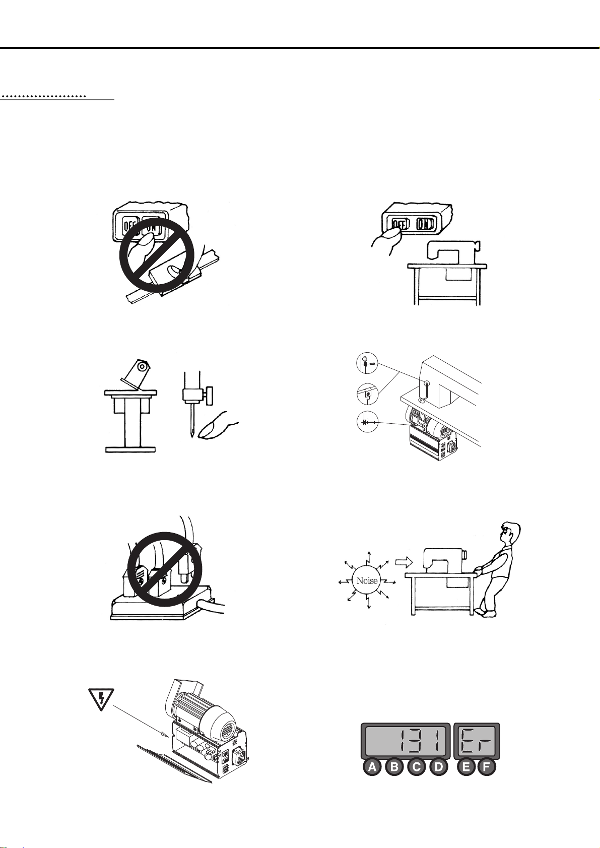
1. Do not turn on the power while stepping on the pedal.
22
2. Turn off the power when leaving the servomotor overnight.
3. Turn off the power when servicing the servomotor or changing
the needle.
4. Be sure to keep the servomotor securely grouned.
5. Do not connect multiple servomotor power plugs to the same
power strip.
6. Install the servomotor away from noise sources, such as highfrequency equipments and welding machines.
7. Avoid electrical shock when servicing the controller box. (Wait for 6
minutes before opening the cover after turning off the power.)
8. When an error message “Er”sppears on the digital display,
take a note of the “Er” code, and then turn on and off before
resuming operation(Contact the local dealer if “Er” message
persists on the display)
Page 9
9
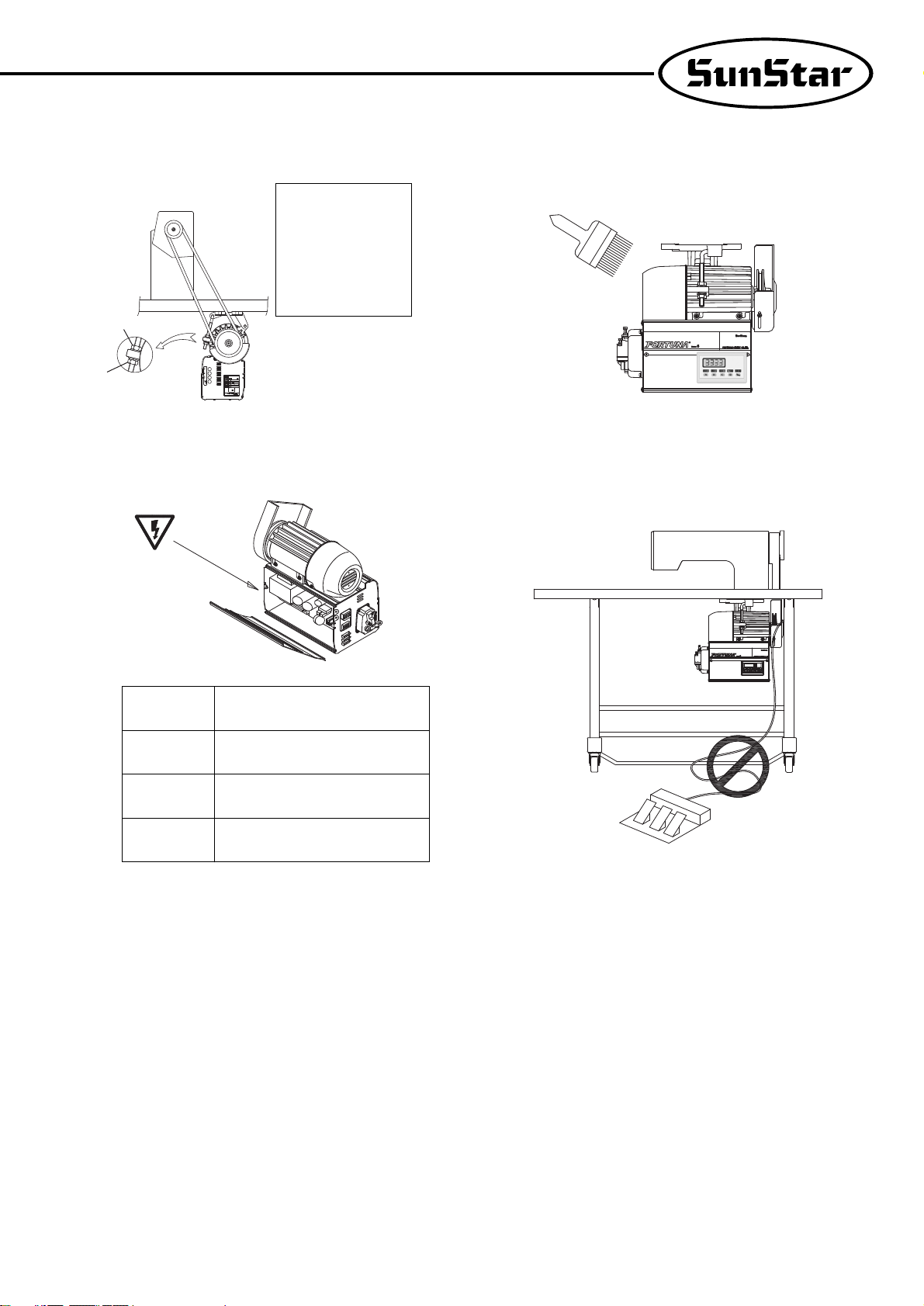
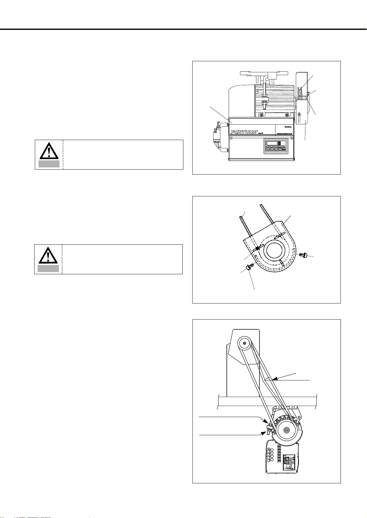
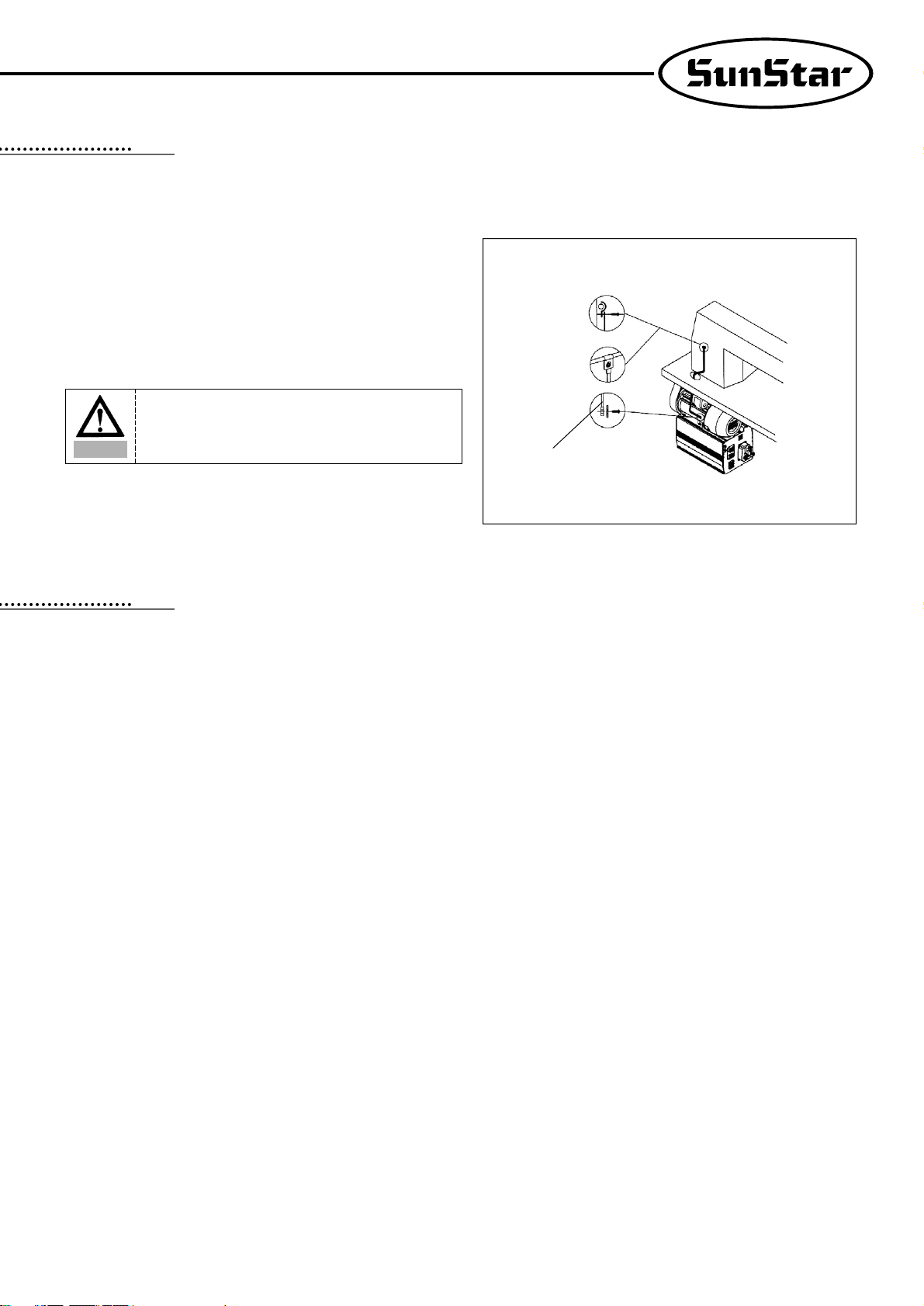
9. Adjust the belt tension to the optimum level.
Belt-tension adjustment should
be performed after the motor is
mounted on the table : First,
loosen both the upper and
lower anchoring bolts(①, ② ).
The belt tension will then be
adjusted by the weight of
servo motor itself. Fasten both
anchoring bolts.
10. Clean it every two or three weeks so that no dirt or a dirty
substance may be piled up.
11. When replacing the fuse, use a standard item, opening the
cover as shown in the diagram.
12. Make the length of the cable connected with an outside parts
like stand-up pedal as short as possible.
F1
F2
F3
F4 250V/1A
250V/6.3A
250V/15A
250V/15A
①
②
Page 10
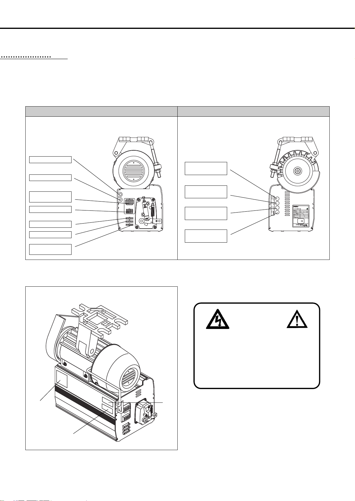
Control box right sideControl box left side
10
LOCATING AND USING PARTS OF THE CONTROLLER BOX
1) Left and right side of control box
2) Rear panel
① Caution
② Motor
③ AC INPUT
②
③
33
Motor Power Cable
AC Power switch
Standard Solenoid
Connector
Switch and Lamp
Foot-lift Solenoid(Green)
Right lift Solenoid(Blue)
Tension-release and
Auxiliary solenoid(White)
Hazardous voltage will cause injury.
Be sure to wait at least 360 seconds before
opening this cover after turn off main switch and
unplug power cord.
고압 전류에 의해 감전될 수 있으므로 커버를 열 때
는 전원을 내리고 전원 플러그를 뽑고 나서 360초간
기다린 후 여십시오.
WARNING
경고
Encoder Connector
(Green)
OPTION
Connector for Position
Sensor(Black)
Program Unit
Connector(White)
①
Page 11
11
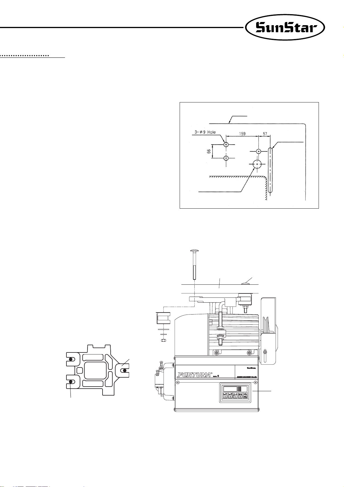
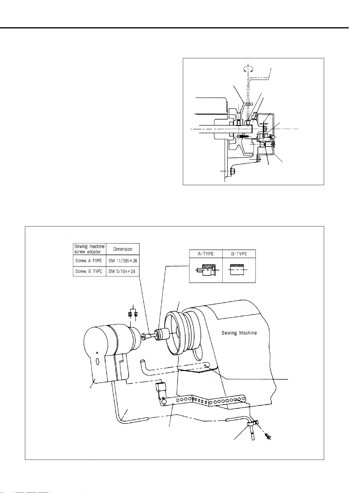
1) Mounting your Servo Motor on the table
② Insert three motor-fixing bolts through the three holes on the table. Attach the motor base padded with vibration-proof rubber, and slide
flat and spring washers over the bolt stems, and then fasten the bolts with nuts.
③ Make sure that the center of motor pulley is matched to that of the sewing machine before tightening the motor-fixing bolts and nuts.
① Make sure that the holes are bored on the table as shown in the
figure.
INSTALLATION
44
Table
Belt Hole
ф41 Cable-Hole
R
Motor-Fixing Bolts
Motor-Fixing Bolts(3ea)
Motor-Fixing Bolts(3ea)
Controller Box
Vibration-Proof rubber
Table
Flat Waser
Spring Waser
Nut
Base
Page 12
12
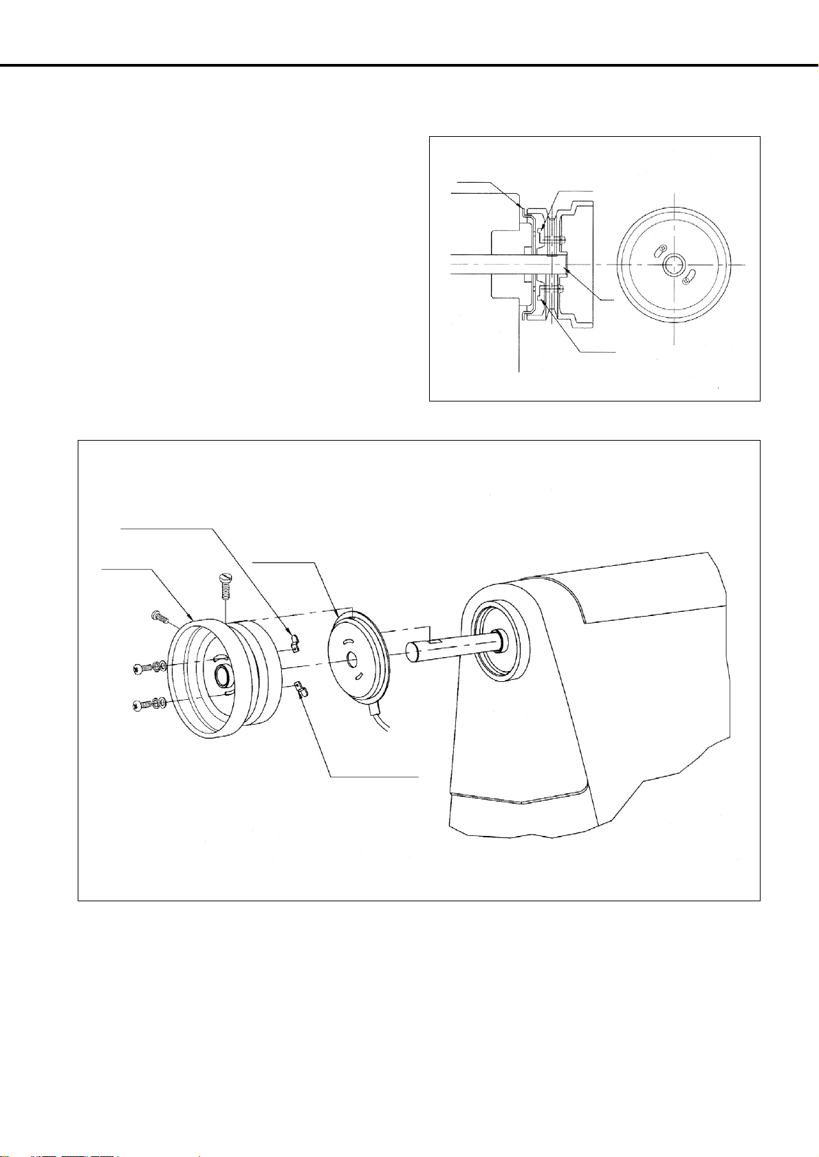
2) Assembling the belt cover and adjusting the belt
tension
(1) Belt cover assembling procedure
① Upon the completion of the motor mounting, bring the two
pulleys of motor and sewing machine closer to each other, by
pulling back the sewing machine. You can then mount the belt
easily as shown in the figure.
② Place the belt cover ‘B’, making sure that the belt cover does
not contact the belt, and then fasten the cover with the fixing
screw.
(2) Adjusting the belt tension
① Optimum Tension Level:The optimum tention level is
achieved when the belt is pushed by 5-10mm when the top
surface portion of the belt at about 30-50mm above the tabletip
is pressed by a finger with a force of~1㎏m/sec2or 1 Newton.
② Adjusting the Tension Level:If the tension level is out of the
optimum range, adjust the tension as follows. First, loosen both
the upper and lower nuts for the anchor bolt, letting the belt be
stretched by the motor weight itself. Second, tighten the upper
nut only to the extent that the motor does not move. Third,
fasten the bottom nut tightly so that the motor is securely fixed.
Controller Box
Belt Cover “A”
Belt Cover “B”
Belt
Belt Guide Fixing Screw
Belt Cover Fixing Screw
Belt Guide
Pulley
Belt Guide
Fixing
Screw
Upper Nut for the Anchor Bolt
Lower Nut for the Anchor Bolt
Warning
Do not remove the belt cover.
If a finger slips into the belt, it might be broken or
cut off.
Warning
Make sure that the power is off before
assembly.
5~10mm
1kg
30~50mm
→←
↕
Page 13

13
3) Mounting and adjusting the foot-lift solenoid
(1) SunStar KM-235 Model
① Attach the main power switch first since the power switch is
located normally in between the solenoid brackets.
② By referring to the figure on the right and the mounting
instructions enclosed in the packaging box, locate the insertion
surface of the oil pan, and then attach the foot-lift solenoid.
(2) SunStar KM-250 Model
① First, assemble a panel for the attachment of presser foot
solenoid on the back of KM-250.
② Attach the presser foot solenoid to a bracket “A”.
③ Attach the bracket “A”with the presser foot solenoid to the
panel above.
④ Attch a crank to a solenoid shaft and then connect it to a
sewing machine.
⑤ Place a cover on the solenoid.
(3) SunStar Special-specification models
The same mounting procedure for KM-235 model is applicable
for other models listed below.
(4) Adjusting the stroke(Gap) of the automatic foot-lift
solenoid
① Check point
Check to make sure that the stroke-adjusting screw is
located at the center of the solenoid axis, i.e., the solenoid
should be assembled in parallel with the bottom surface of
the table. If the solenoid is not in paralle, make an
adjustment so that the screw is in parallel with the center of
the solenoid axis using the connection link-fixing screw.
② Adjusting Procedure
The verical travel distance of the presser foot can be adjusted by
the stroke-adjusting screw. First, Loosen the two fixing screws,
and adjsut the vertical stroke using the stroke-adjusting screw.
loosening and tightening the stroke-adjusting screw will decrease
and increase the verical stroke of the presser foot respectively.
After the adjustment, fasten the fixing screw tightly.
No.
1
Solenoid No.
SPF-2
Applicable Models
KM-235A, B
Oil Pan Insertion Surface
Mounting Position
for Legs(4)
Mounting Position(4)
for Automatic
Foot-Lift Solenoid
Oil Pan Insertion Surface
Mounting Position(4)
for Automatic
Foot-Lift Solenoid
Belt Holes
Belt Holes
Oil Pan
Fixing Nuts
Solenoid Axis
Stroke-Adjusting Screw
Connection Link-
Fixing Screw
※Specification viewed from the table bottom
※Specification viewed from the table bottom
※KM-250 Rear Panel
Solenoid Bracket A
Cover for Foot-Lift Solenoid
No.
1
2
3
4
5
6
7
Solenoid No.
SPF-3
SPF-4
SPF-6
SPF-8
SPF-9
Applicable Models
KM-750-7, KM-750BL-7
KM-790-7, KM-790BL-7
KM-857-7, KM-867-7
KM-560-7
KM-957-7, KM-967-7
KM-757-7
KM-640BL-7
Page 14
14
4) Mounting the position sensor (Synchronizer) and
setting the film
(1) Mounting the position sensor(Synchronizer)
① SunStar thread-cutting sewing machine.
All SunStar thread-cutting sewing machines are equipped
with a position sensor. Users, therefore, are required to the
adjust the film position, if necessary, as shown in the figure.
② All other sewing machines(including other manufacturers’ brands)
First, attach the position sensor-mounting adapter to the upper shaft of the sewing machine. Second, attach the position sensor-fixing
plate to the body of the sewing machine as shown below in the figure. Third, secure the position sensor to the adapter with the fixing
screws.
L Wrency
Pulley
Synchro shaft-fixing screw(2)
Synchro shaft
Photo film
(Adjusted left and right)
Photo INTERRUPT
COVER
Upper Shaft
P.C.B Holder
Adapter
Position Sensor-Fixing Bolts
Position Sensor
Cable
Position Sensor-Fixing Plate(Type B)
Nylon Cable Tie
Fiixing Bolt for Position
Sensor-Fixing Plate
Position SensorFixing Plate(Type A)
Pulley
Page 15
15
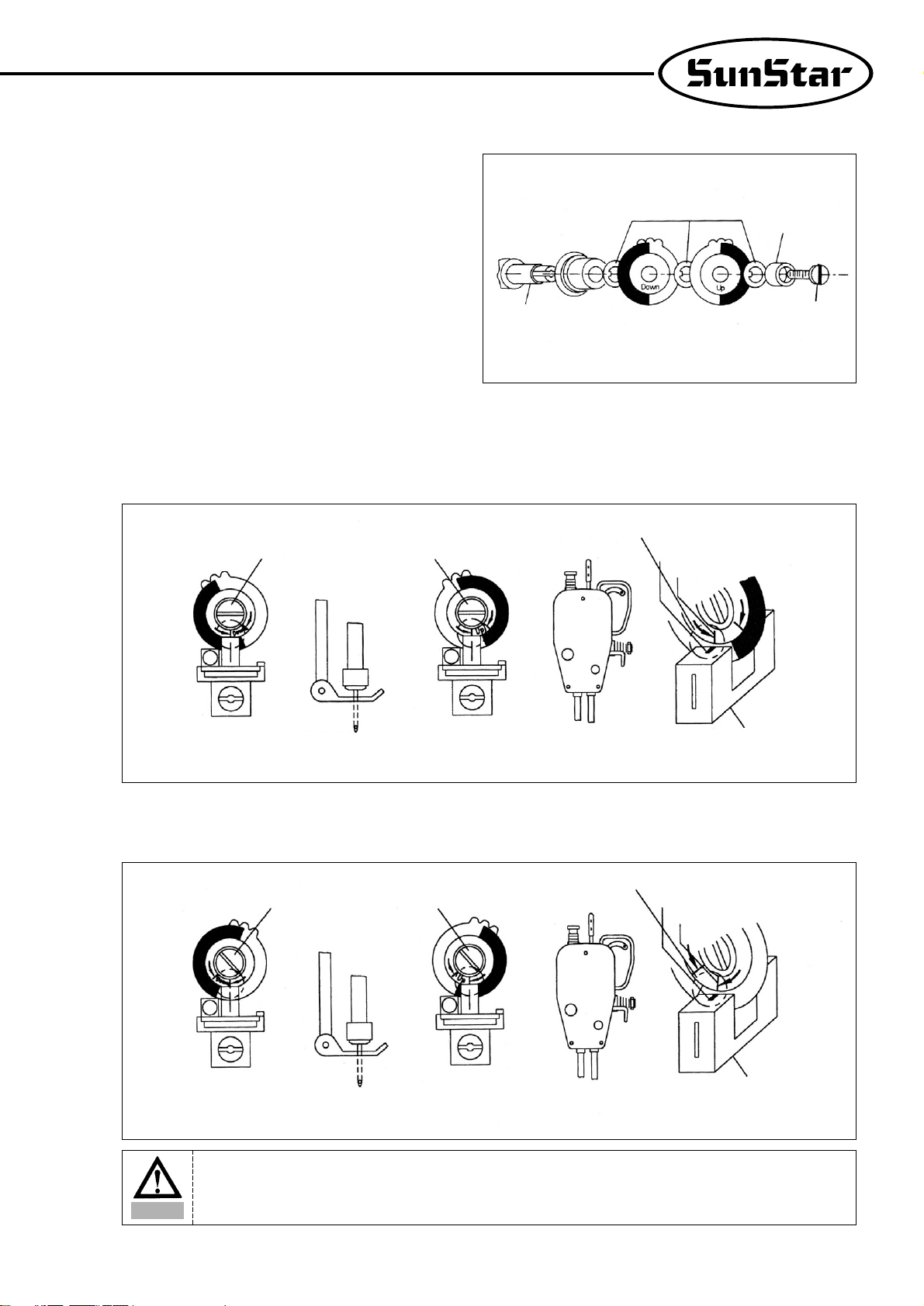
(2) Adjusting the film of the position sensor
① Assemble the films and position sensor in the order as shown
in the figure.
② Upon the completion of the assembling, position the needle shaft tight at the rising point from the lowest needle position by manually
rotating the pulley. Loosen the film-fixing screw, and adjust the DOWN film so that the film-adjsting line and the sensor housing
calibration line are matched. Tighten the film-fixing screw just to the extent that the film can not be rotated. Likewise, position the thread
take-up at the highest position. Loosen the film-fixing screw, and adjust the UP film as shown in the figure, while using caution not to
move the DOWN film which is already adjusted earlier. Tighten the adjusted film with the fixing screw.
(3) Adjustion the films of reverse rotation sewing machines
※For reverse-rotation sewing machines, the film-adjusting lines located at right edge of the “UP”and “DOWN”film should be matched to
the center line of the sensor.
Fixing Washer
Fixing Bushing
Film-Fixing Screw
Position Sensor Shaft
Fixing Nut Fixing Nut
Fixing NutFixing Nut
Setting Position
Setting Position
Sensor Calibration Line
Sensor Calibration Line
Film-Adjusting Line
Film-Adjusting Line(Reverse Rotation)
Sensor Housing
Sensor Housing
The highest position
of take-up lever
The highest position
of take-up lever
Up Film Adjustment
Up Film Adjustment
Down Film Adjustment
Down Film Adjustment
2mm turning around
from the lowest
position of needle bar
2mm turning around
from the lowest
position of needle bar
Caution
After adjustment the film of the position detector, be sure to rotate the motor for 3~5 seconds by pedalling so
that the Controller may remember location of the film.
Page 16
16
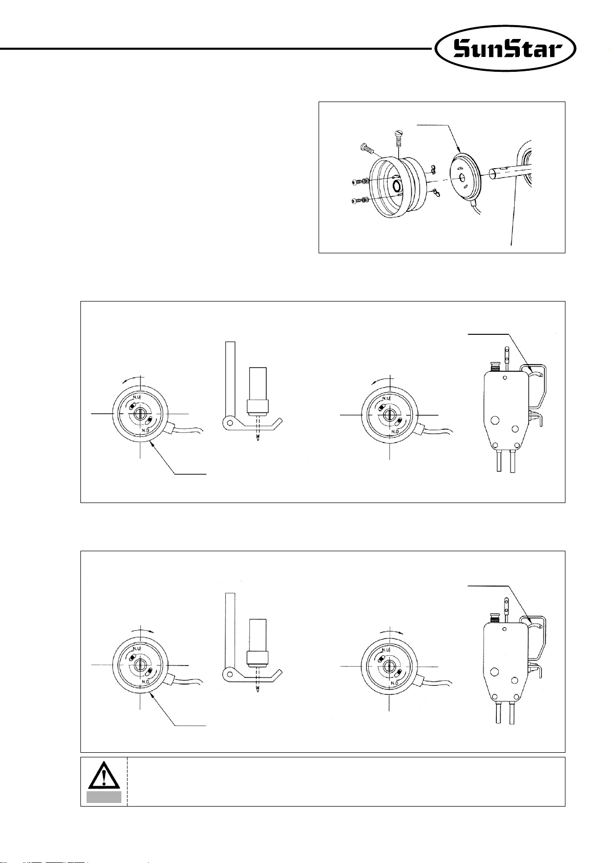
5) How to equip and adjust a built-in location
detector(synchronizer)
(1) How to equip the built-in location detector
(synchronizer)
▶ In case of a SunStar thread trimmer
When a built-in location detector(synchronizer) for the
sewing machine with the SunStar thread trimmer is
equipped, all that the users need to do is to simply adjust the
location of magnetic for detection according to their needs.
Locate detector
(synchronizer)
Position magnetic up
Upper
Shaft
Position magnetic down
Position magnetic up
Sewing machine
pulley
Locate detector
(synchronizer)
Position
magnetic down
Sewing machine
Page 17
17
(2) How to adjust the magnet of the location detector
① Assemble the detector in order following the pictures.
② Once assembling is completed, power the controller on and step on the pedal. At this time, make sure that the needle moves up and down.
Stop the needle at a desired location by moving the magnet back and forth along the location where the needle stops.
(3) How to adjust a location detector in case of a reverse rotation sewing machine
※It is the same as that used for the normal rotation direction
Locate detector(synchronizer)
Normal rotation
direction
Reverse rotation
direction
Reverse rotation
direction
Normal rotation
direction
The highest position
of take-up lever
The highest position
of take-up lever
Locate detector
(synchronizer)
Locate detector
(synchronizer)
2mm turning around
from the lowest
position of needle bar
2mm turning around
from the lowest
position of needle bar
Caution
After adjusting a location detector, rotate the motor by stepping on the pedal for 3~5 seconds so that a
controller can remember the location.
Page 18
18
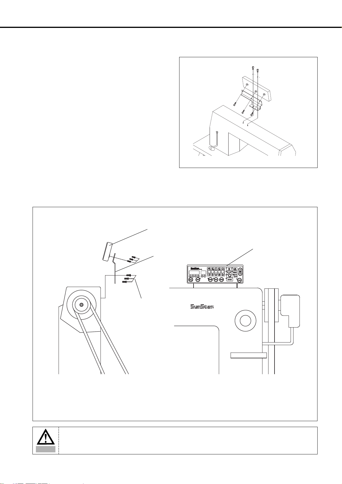
6) Mounting the Program Unit(P/U)
(1) SunStar KM-235 Sewing Machine
First, attach the P/U bracket to the P/U using three fixing screws
and a supporting bolt with nut attached on it as shown in the
figure. Second, securely attach the P/U to the head of the sewing
machine using two fixing screws and washers, keeping a 3~4mm
distance between the bottom surface of the nut and the base of the
supporting bolt.
(2) Other SunStar thread-machine
First, attach the P/U bracket to the P/U using the four fixing screws. Second, attach the P/U to the main body of the sewing machine using the
three bracket-fixing screws as shown in the figure.
Program Unit
Program Unit
P/U Bracket
P/U Bracket-Fixing
Screw(3)
Caution
Fix the cable using the cable tie so that cable is not in the way of the belt.
Page 19
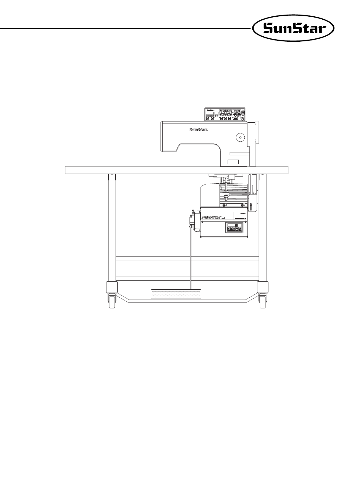
19
7) An example of installing the SunStar sewing machine
Page 20
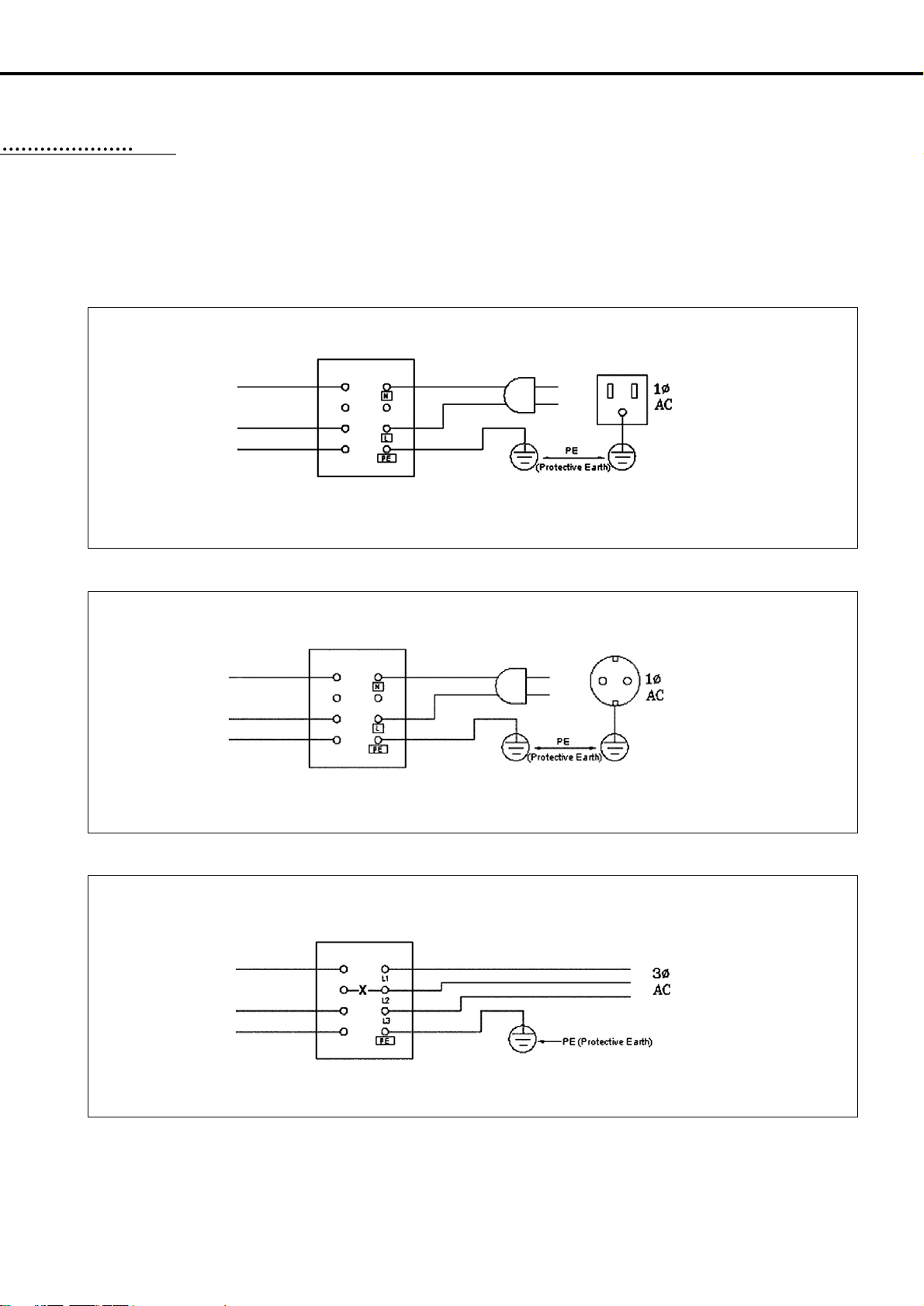
20
1) Specification of the power plug
(1) Single phase 100V~120V
(2) Single phase 200V~240V
(3) Three phase 200V~240V
※Be sure to connect Protective Earth
2) Specification of electric current in wiring of power plug
Be sure to use wiring materials which can stand electric current of higher than 15A.
WIRING AND GROUNDING
55
110V
220V
220V
EARTHV
EARTHV
EARTHV
Switch Box
Control Box
Control Box
Control Box
Switch Box
Switch Box
Page 21
21
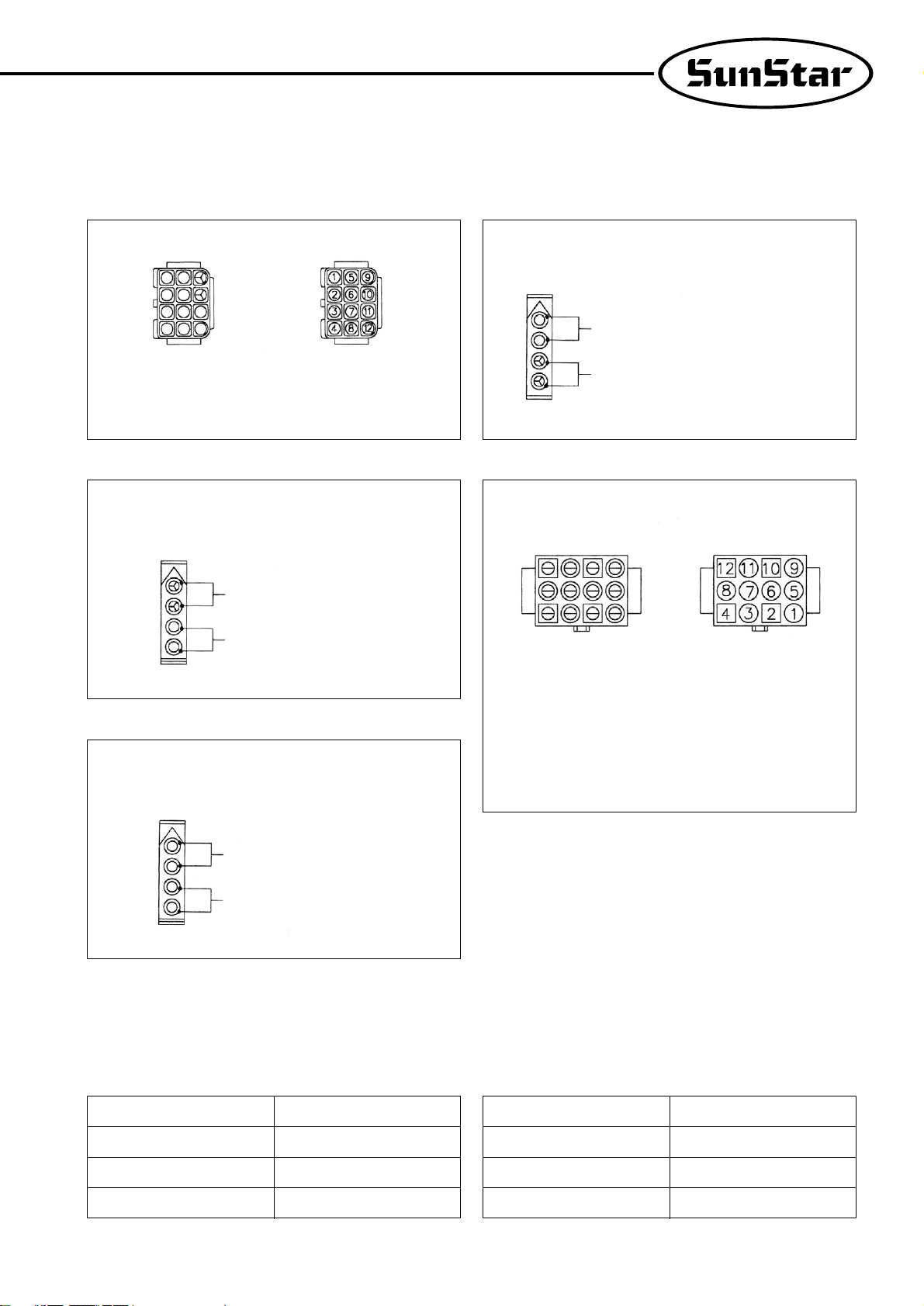
3) Name and description on the outside connector of control box
① Standard solenoid connector ④ Tension-release and auxiliary solenoid
② Foot-lift solenoid ⑤ Switch and lamp(Used in twin-needle sewing machine)
③ Right/Left solenoid(Used in twin-needle sewing machine)
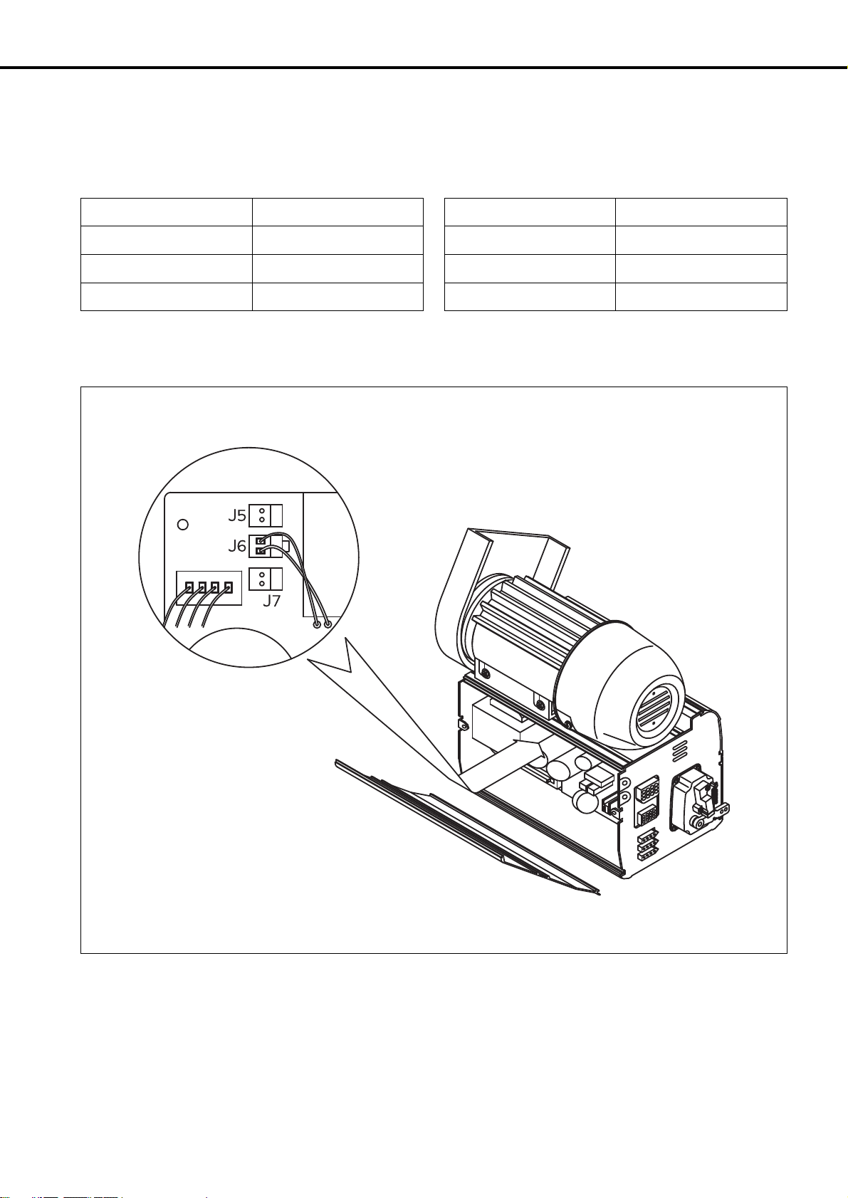
4) How to change the electric voltage supplied for solenoid (The factory installed setting is:J6)
※This is to make the movement of solenoid smooth in times of fluctuation in the incoming electric voltage.
① Set Value for electric voltage supplied (for 220V series) for Solenoid against the incoming voltage.
For 30V-regular Solenoid For 24V-regular Solenoid
Incoming Voltage Set Value
Below 210V J5
210V~230V J6
Above 230V J7
Incoming Voltage Set Value
Below 180V J5
180V~190V J6
Above 190V J7
[ Shape of pin ]
Connector Color:Green
Connector Color:Blue
[ No. of pin ]
Connector Color:White
4, 8:GND, VDC
(DC 46V or DC 32V)
9, 10:Button Ⓑ to insert/delete the
back-tack operation
11, 12:Button Ⓐ for manual back-
tack operation
1, 5:Back Tack Solenoid
2, 6:Thread-Cutting Solenoid
3, 7:Wiper Solenoid
Foot-Lift Solenoid Switch
Auxiliary Solenoid
Tension-Release Solenoid
①+5V
②+5V
③ L LED
④ R LED
⑤ L S/W
⑥ R S/W
⑦ GND
⑧ 4/4 (N.C)
⑨ 3/4 (N.C)
⑩ 2/4 (N.C)
⑪1/4 (N.C)
⑫ (N.C)
Right-Needle Control Solenoid
Left-Needle Control Solenoid
Foot-Lift Solenoid
[ Shape of pin ] [ No. of pin ]
Page 22
22
② Set Value for electric voltage suplied (for 110V series) for Solenoid against the incoming voltage.
③ Setting of pin
For 30V-regular Solenoid For 24V-regular Solenoid
Incoming Voltage Set Value
Below 100V J5
100V~120V J6
Above 120V J7
Incoming Voltage Set Value
Below 90V J5
90V~100V J6
Above 100V J7
Page 23
23
▶ Method
Connect the motor and sewing machine using the ground wire
(green, green/yellow) as shown in the figure. Make sure that the
factory-connected ground wire between the controller box and
motor is securely in place.
CONNECTION THE EARTH WIRE OF THE SEWING MACHINE AND MOTOR
66
1) Before the power is on...
① Make sure that the incoming voltage is in accordance with that shown in the name plate of the Control box.
② Check whether the following connectors are connected.
•Connector for incoming AC power source
•Connector for motor power
•Connector for motor encoder
•Connector for position detector
•Connector for others (option, knee-lift, program unit etc.)
③ Check to see whether the belts are in touch with the wiring.
④ Check the tensile strength of the belts.
⑤ Check to see the fixing nuts for pulley are tightly fastened.
⑥ Check whether the sewing machines are right kinds (Chain Stitch S/M, Lock Stitch S/M)
⑦ Check the rated voltage for Solenoid (Refer to “How to change the electric voltage supplied for Solenoid”))
2) After the power is on...
① Check whether the lamp for the position detector is on. (Except in the case of built-in position detector)
② Check whether the program unit is working.
③ Check the direction of rotation of the Sewing Machine.
•In case the direction of rotation is not right, action shall be taken to change set it right, referring to “the methods of changing the
program and the list of changing functions”(N. 65 in Group “A”)
④ Check to see whether there are abnormal heat, smell or noise nearby .
•In case there are, turn the power off and call our regional office.
THINGS TO BE CHECKED AFTER INSTALLATION
77
Ground Wire(Green)
Caution
Failure to ground the motor can cause abnormal
operations, such as overspeed rotation or unwanted
stitching.
Page 24
24
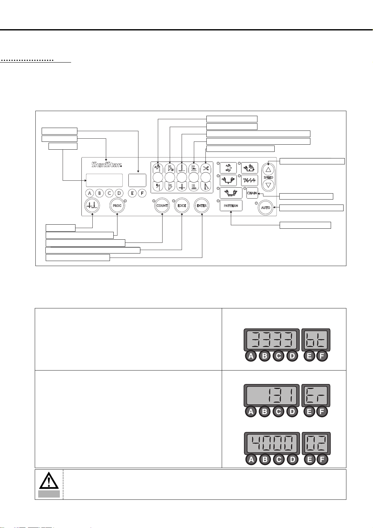
1) Program unit part names
2) Program Unit Method of Use
(1) 4-Digit Displayer and 2-Digit Displayer Functions and Method of Use
A. 4-Digit Displayer and 2-Digit Displayer Functions
PROGRAM UNIT PART NAMES AND METHOD OF USE
88
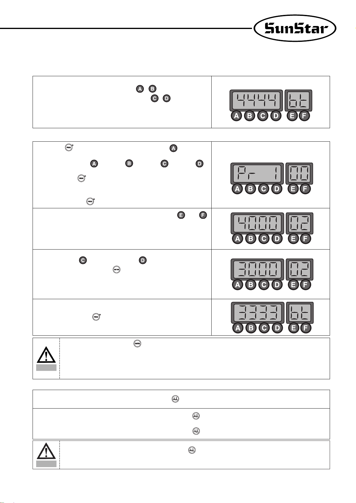
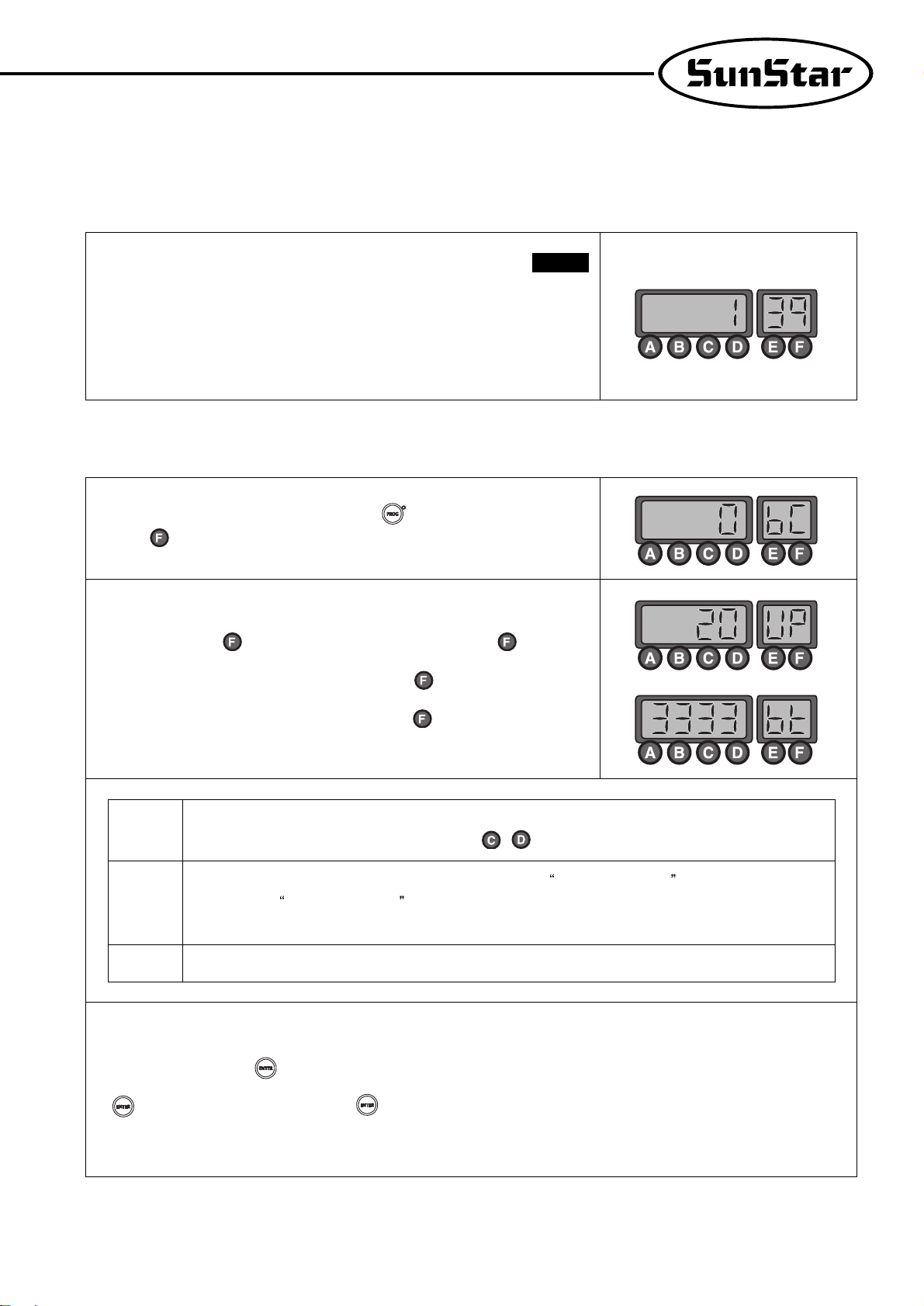
① When you turn the power on, you will see a screen as shown in the figure.
The 4-digit displayer shows the start and end B/T sewing and the 2-digit
displayer shows the current abbreviation for the letters or numbers shown in
the 4-digit displayer (bt: the abbreviation for back tack),
<Initializing screen>
<Example of error detection>
<Example of selection of number 2 item in Group A>
② The 4-digit displayer shows the error number for each type of error
discovered and also shows the programmed value after it has been
programmed. The 2-digit displayer shows the number of the parameter
specific item's content or name which is shown in the 4-digit displayer.
2--Digit Displayer
Sunstar Logo
4-Digit Displayer
1/2 Stitch Button
Button for Program Change
Button for Counter Use after Counter Programming
Button to use Edge Sensor Selection after Edge Sensor Programming
Button to Save Program Changes
Pattern Work Selection Button
Start B/T Selection Button
End B/T Selection Button
Button to Select Needle Plate Location When Machine Stops
Button to Select Presser Foot-lift Location When Machine Stops
Thread-trimmer and Wiper Selection
Button to Change the Sewing Speed Installation
Pattern Work Connecting Button
Constant Sewing Speed Selection Button
Caution
The 4-digit displayer and 2-digit displayer show the current condition. Therefore the user should always check it
before using the machine.
Page 25
25
B. Method of Use: 4-Digit Displayer and 2-Digit Displayer
a. Method to change the start and end B/T stitch numbers
In order to change the start B/T stitch numbers which is programmed when you
first purchase this machine, you must use the , buttons. If you want to
change the end B/T stitch numbers, you must use the , buttons.
•The program range is from 0 to 9.
(Ex: How the screen looks when changing both start and end B/T stitch
numbers to 4).
b. Method to check or change the specifics of the parameter
(2) Method of Use:½ Stitch Button Function
① Press the button and as you press it, also press the button. Then
you can either check or change the programming items for the parameter of
group A. (A group: , B group: , C group: , D group: )
※ Users should turn the machine off to select B, C, or D group. While
pressing the button, turn the power switch on. The screen will be
changed to the initial screen after showing the "PrEn" message. Then, the
users can select B, C, or D group by pressing B, C, or D button while
holding program button.
② You can move to the parameter item you want with the and
buttons. The parameter item number will appear in the 2-digit displayer and
the wanted value will appear in the 4-digit displayer.
(Ex) Screen showing the maximum speed limit preset in the item 2 of A group)
③ After using the (increase) button and (decrease) button to choose
the value you want, press the (Enter) button and save the value you
chose. (Ex: Reducing the maximum sewing speed limit from 4000RPM to
3000RPM).
④ After saving, press the button and go back to the initial screen.
① When necessary, make ½ stitches by pressing the ½ stitch ( ) button.
② When the needle plate makes a down stop, shortly press the ½ stitch ( ) button once and the needle plate will make an up stop.
And when the needle plate makes an up stop, shortly press the ½ stitch ( ) button once and the needle plate will make a down stop.
Caution
•Be aware that if you don't press after changing the programmed value for the parameter item, the value will not be saved.
•When the B, C, or D group selection is completed, users should turn off the machine first and restart to secure the selected
group.
•If the user changes the programmed value from the parameter specifics carelessly, the user may cause break down or physical
damage to the machine. The user must therefore be well-trained before changing the parameter group.
Caution
Be aware that if you are continuously pressing the ½ ( ) button, the machine will keep on moving at the ½ stitch
speed.
Page 26
26
(3) Method of Use: Start B/T Button
This button is used when the user wants to prevent threads from loosening at the end of the sewing work. If the user presses this button
in sequence, the location on the lights will change. This button offers the following three functions.
Using the A, B buttons in the 4-digit displayer, the user can program the B/T number of stitches he/she wants.
When sewing starts, B/T
sewing does not operate.
When sewing starts, B/T
sewing is operated with
the
button.
When sewing starts, B/T
sewing is operated with
the
button.
(4) Method of use: End B/T Button
This button is used when the user wants to prevent threads from loosening at the end of the sewing work. If the user presses this button
in sequence, the location on the lights will change. This button offers the following three functions.
Using the C, D buttons in the 4-digit displayer, the user can program the B/T number of stitches he wants.
When sewing ends, B/T
sewing does not operate.
When sewing ends, B/T
sewing can be operated
with the
button.
When sewing ends, B/T
sewing can be operated
with the
button.
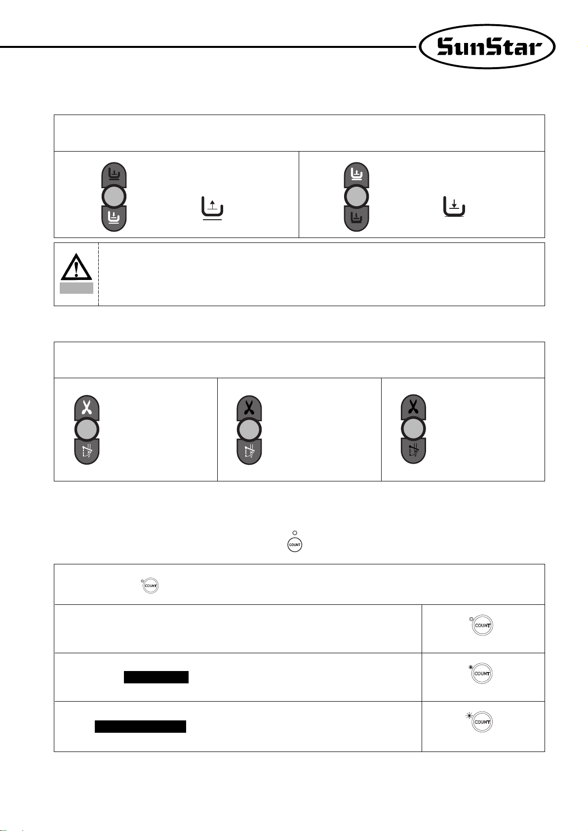
(5) Method of Use: The Needle Plate Position Selection Button When the Sewing Machine Stops
When the user turns the power on, one of the up stop or down stop lights in the program unit panel needle plate is always left on. The
user can change the stop location by pressing the button.
When machine stops while sewing, the
needle plate makes an up stop.
When machine stops while sewing, the
needle plate makes a down stop.
Caution
Be aware that if the start B/T stitch is set to '0' in the 4-digit displayer, the start B/T sewing is impossible.
Caution
Be aware that if the end B/T stitch is set to '0' in the 4-digit displayer, the start B/T sewing is impossible.
Page 27
27
(6) Method of Use: The Presser Foot-lift Location Selection Button When the Sewing Machine Stops
When the user turns the power on, one of the up stop or down stop lights in the program unit panel pressser foot-lift is always left on.
The user can change the stop location by pressing the button.
When the machine stops while sewing, the
presser foot-lift stops at the top.
When the machine stops while sewing, the
presser foot-lift stops at the bottom.
(7) Method of Use: Automatic Thread Trimmer and Wiper Selection Buttons
These buttons offer the function of automatic trimming and wiping after sewing. By pressing these buttons in sequence, the user can use
one of the following three functions. The light shows the function that is currently being used.
Automatic trimmer and wiper
do not operate
Only automatic trimmer
function is operate
Both automatic trimmer and
wiper operate
Caution
If the user uses the automatic up stop function of the presser foot-lift when the sewing machine stops while sewing, it
may cause damage to it because it has been left up for an unnecessarily long time. Be aware that to prevent the
foot-presser solenoid from being damaged, it is programmed to automatically come down when a certain amount of
time passes.
(8) How to use product counter and bobbin counter
※ To use the counter function, set the detailed functions under parameter B-Group.
① When product counter and bobbin counter are not used
② When product is set
counter function
③ When is set
bobbin counter function
Repeatedly press the ( ) button in the program unit to change the status of the lamp and functions as below.
① How to set product counter and bobbin counter
A. Set/clear product counter and bobbin counter using the button in the program unit
<When the lamp is off>
<When the lamp is on>
<When the lamp is flashing>
Page 28
28
② How to use detailed functions of product counter and bobbin counter
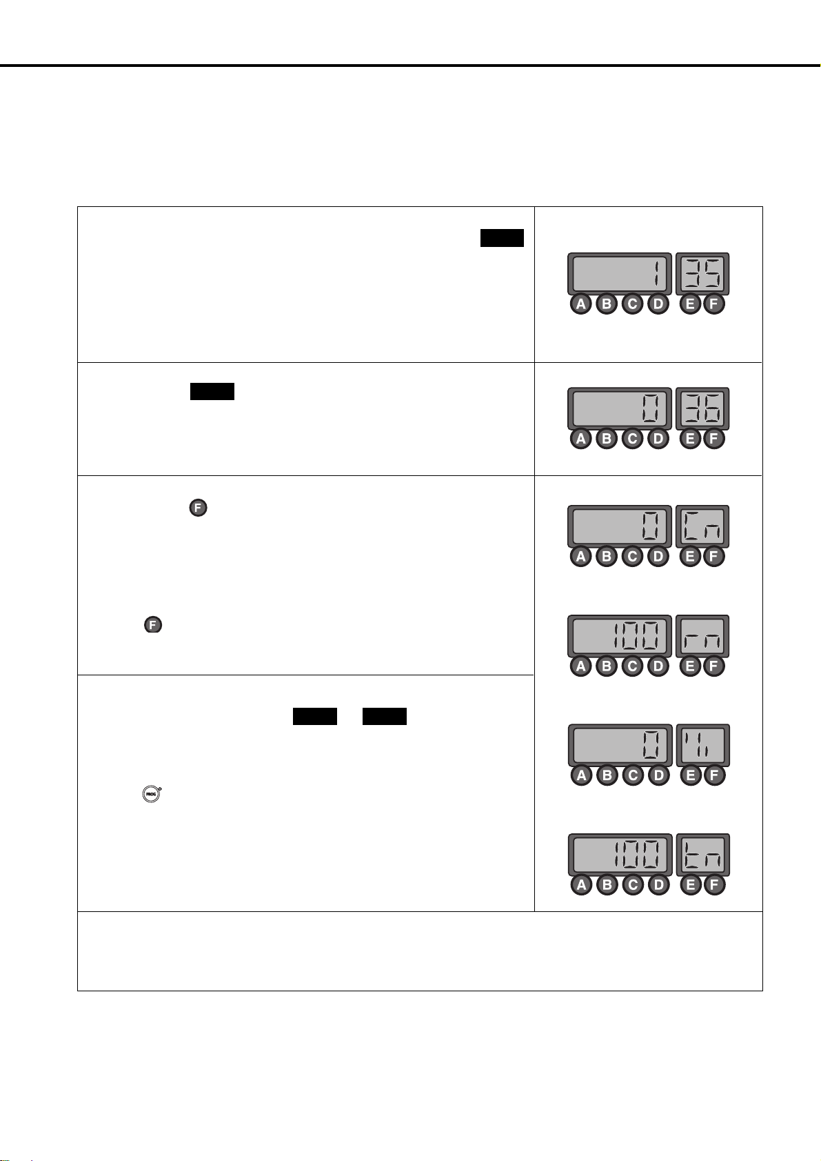
A. How to use the detailed functions of product counter
T o use the counter function, set the detailed functions beforehand.
② Set the parameter to select the type of product counter
•1: Up counter
•0: Down Counter
※ The default value is set at “1”.
B-36
③ Press the counter button to set the counter function. Press the button to check and
set the detailed data of the counter.
•Cn: The current counter amount
•rn: The remaining amount
•%: The progress
•tn: Total target amount (Default: 100)
※ Press button repeatedly to see the above detailed data in order. The user may
set up the current counter amount (Cn) and the total target amount (tn) as desired.
④ After the total tar get amount is set, use and to set the movements.
<Set value of B-37>
•0: When work is finished, the buzzer will go off and sewing may begin
•1: When work is finished, the buzzer will go off and sewing may begin only when
the button is pressed
•2: When work is finished, the buzzer will not go off and sewing may begin
< Set value of B-38>
•0: No returning to automatic initial value when counting is complete
•1: Returning to automatic initial value when counting is complete
B-38
B-37
① To use the product counter function, first set the value of the parameter
(group B, item 35) as desired.
•0: Set the external counter switch on
•1: Set the automatic counter on after trimming
※ As the default value is set “0”, the counter will not run if there is no external counter
switch.
B-35
<The current amount>
<The remaining amount>
<The progress>
<Total target amount>
[ Caution ]
When B-38 is set at “0”, the value will keep on going up/down even when counting is complete. The user will need to re-set the
value of Cn to restart.
Page 29
29
B. How to use the detailed functions of bobbin counter
Bobbin counter is designed to check the remaining amount of the lower thread.
a. T o use the counter , set detailed functions beforehand.
b. Detailed functions of bobbin counter
① To use the bobbin counter function, first set the value of the parameter
(Group B, item 39).
•0: Bobbin counter function not used
•1: Bobbin counter function used
※ The default value is set at “0”. At this point, the bobbin counter will not start even
when the counter button in the program unit is set at bobbin counter function.
B-39
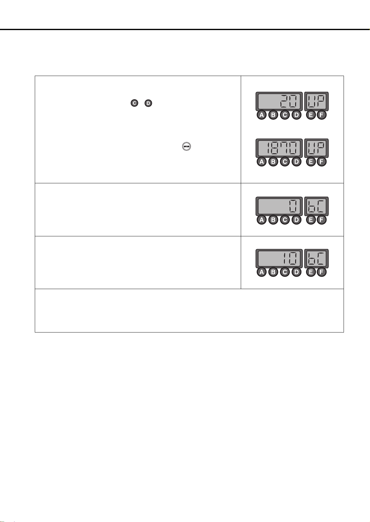
① Select the bobbin counter function by pressing button to get the lamp flashing.
Press button and the display will change
as shown in the right. “bc”stands for bobbin counter.
② At this point, press button to change the display to “UP”. Press button again
to go back to the initial display of “3333 bt”. Press again to change to “bc”as
explained in ①. The display will change by pressing button.
•[bc]
•[UP]
•[bt]
It stands for the Bobbin Counter; the value will be increased from “0”.
(Initial value: 0, Set range: 0~9999, How to set: use / button)
This value will go up in proportion to the increasing ratio of BC(Bobbin Counter) . Use this value to get the
initial value of
BC(Bobbin Counter)
(Initial value: 0, Set range: 0~9999, Set manual increase/decrease function with C/D button)
Back-tack function that is shown in the initial display
[ Caution ]
※Pay caution when using button, designed to perform special functions for bobbin counter.
• button (Store counter value) : Press button when “bc”or “UP”is shown on the display. The current indicated value
will be stored as value of bobbin counter.
Page 30
30
c. Setting Bobbin Counter Functions
① When you start new sewing work, you must re-set the value of bobbin counter. Refer
to the following if you do not know your re-set value.
•First move to “UP”display and use , button to change the value to “0”.
•Replace old lower thread with the new one. The amount of the lower thread must be
consistent.
•Begin sewing. The more you sew , the higher the value of “UP”will be.
•Continue sewing until you run out of the lower thread.
•When there is no lower thread left during sewing, press button to store the
counted value.
•Before saving, subtract some 10~20 from the value in order to reflect the counted
value after the lower thread ran out.
② When the bobbin counter setting is complete, move to “bc”display.
③ The value of “BC(Bobbin Counter)” increases gradually when sewing begins after
completing set-up.
[ Caution ]
※ Before using the bobbin counter function, move to “bc”display or initial display. If you start working from “UP”display, the
value of counter will go up.
Page 31

31
d. When bobbin counter is complete
① Replace the old lower thread with the new one and start sewing, then the value of
“BC(Bobbin Counter)” will go up gradually.
② Take note that the buzzer will go off when the value goes up, and the gap between that
value and setting value narrows under 20. This is to warn that there is little lower
thread left.
③ The value of Bobbin Counter is reached at setting value, the stitching will be stopped
and the buzzer will go off and the monitor will start blinking.
④ When sewing stops after counting is complete, use the following method to return.
•Press the button to change the value of “BC” to the “0” automatically.
(AUTO CLEAR/PRESET)
[ Caution ]
※ To use the bobbin counter function, first set B-Group 39 to “1.”
※
Use button to change the display to set/clear the value of bobbin counter during sewing.
※
Wind the lower thread with consistency to ensure the proper use of bobbin counter functions. Counter functions may work
differently depending on lower thread and sewing conditions.
Page 32

32
(9) Method of Use: Pattern Work Selection Button
A. Method to Set Up the Pattern Work Function
This function is used when you need to continuously work on a sewing material. If the
light goes on after pressing the button, you can use the pattern sewing function.
B. Method of Use of Pattern Sewing Specific Functions
① Cautionary words when using the pattern function
•Before using the pattern function, finish the trimming work and turn on the pattern switch light.
•If the user presses the pattern switch twice when he/she is not using the pattern function, the light will go off and he/she will be
able to go back to normal sewing. However, if the pattern mode has not been completely finished, the pattern light will not go
off.
•The pattern function sewing speed will be the programmed speed.
•The value set in each pattern mode is not erased when the power is turned off. Therefore, if you want to use the same pattern
again, press the same mode again to use it. However, if the program is initialized, all the formerly programmed information will
be erased and the user must reset the information again.
② Method of use: function
ⓐ first press the button and select the pattern sewing function.
ⓑ Select the pattern you want and the light will go on the pattern you selected.
ⓒ If you press the button, the screen will change and you can use the stitches of
each side of the pattern you chose to program the value.
< Method to program the value of each pattern side >
•Method by using the , buttons
-Inputting directly the number of stitch the user wants by using the buttons C and D.
This method is used when the user already knows the length of the stitches he/she
is choosing.
-Method using the pedal movement
-This is a function used when the user does not know the stitch length and sews
directly to check the number of stitches for the pattern he/she wishes to program. If
the user presses on the pedal after the programming screen comes on, the pedal can
program the number of stitches by using the accelerating and decelerating
characteristics through the pedal's sensors. The standard for choosing the number
of stitches here is slower than the normal sewing speed and the programmed
pattern sewing speed.
-Method using the A button and 1/2 stitch button
-This function is used when the user needs to make small adjustments at the end of
the pattern work. It allows the user to check and program the pattern length while
he/she sews at a slow speed or sews half stitches.
P:When the AUTO light is off, the machine
stops when the pedal is released while
sewing.
A:When the AUTO light is on, the machine
will finish sewing the pattern section even if
user releases pedal while sewing.
<Screen showing thef programming of
stitch numbers for each side>
⇒
ⓓ After programming is finished, press the button and save the set up value. Then press the
button. After the stitch numbers of each side disappear from the screen, you can start
sewing with the programmed value in the pattern sewing function.
ⓔ The pattern sewing speed is constant because it sews at a programmed speed not by the
acceleration or deceleration of the pedal. If you press the pedal after pressing the button and
see the light blink, sewing will continue until it is finished even if you release the pedal.
Caution
•After setting each side of the stitches, the user must press the button to save the programmed value.
•When the pattern has more than one side, the pattern work only operates for the number of stitches programmed
for each side.
Page 33

33
③ Specific items of each pattern
A convenient pattern for straight sewing at constant speed for a definite length. The
sides can be set from 0 to 999 stitches.
A convenient pattern for repetitive 3-sided sewing. Each side can be set from 0 to 999
stitches.
A convenient pattern for 4-sided sewing. Each side can be set from 0 to 999 stitches.
(Used often in square sewing)
A convenient pattern when forward/backward sewing is needed continually.
forward/backward sewing is possible 9 times. Also each side can be set from 0 to 999
stitches.
(This pattern is used for continuous work on back tags of leather belt rings).
A convenient pattern when the user wants to make many-sided patterns. The user can
make patterns of up to 20 sides. Each side can be set from 0~999 stitches.
④ Method of Use:Chain function (pattern linking function)
•First press the button and select the pattern sewing function
•Next, press the button.
•If you press the button, the screen will change as the figure shows on the right.
You can change the number of chains with buttons , .
•If you want to program the number of chains in the pattern you want, use buttons
and, to go to the item you want and press the pattern button.
•After programming the chain numbers as explained above, press the button and
the change of value will be saved. Then press the button to come out from the
chain programming screen.
•If you operate the programmed sewing work, the pattern with the blinking light is
the current work being done and the pattern with the light on continuously is the next
programmed pattern.
※If the user presses the when using the pattern sewing function, the light will
go on and the machine will automatically sew the programmed pattern section
even if the user releases the pedal.
Caution
•After programming the chain function and pressing the button, the set up value is saved.
•If you change the pattern program while sewing, it will sew with the new programmed pattern.
•If the last chain pattern is finished, it will automatically go to the first sewing pattern.
Page 34

34
(10) Method of Use: Constant Speed Sewing (AUTO) Selection Button
(11) Method of Use: Sewing Speed Program Changing Button
A. Method to Check Sewing Speed
This button is used to choose the sewing speed. It offers two functions according to where the light turns on.
•When the light is blinking
- If the user presses on the pedal, the
machine will sew at the programmed
sewing speed.
•When the light is off
- The machine will sew according to the
amount of pressure given to the pedal by
the user.
If you want to check the current programmed sewing speed, you must press the
button. If you briefly press the button button once, the screen shown on your
right will appear briefly and then return to the initial screen.
※ The speed on the screen is the limit of the maximum sewing speed.
B. Sewing Speed Changing Method
① When you want to change the sewing speed, you can see the screen that shows the
current sewing speed by pressing the button or button.
② If you see the current speed on the screen, you can change the speed by using the
and button before going back to the initial screen.
•When you press the buttons twice in sequence: The sewing speed increases/decreases
by 40RPM.
•When you keep pressing the button: The sewing speed increases/decreases rapidly .
Caution
This button works in a different way when using the pattern function. Please refer to section 10).
Caution
The maximum speed and minimum speed limits can be changed by changing the parameter's specific items.
Caution
-Be aware that if you don't press the or button, the screen will automatically go back to the initial screen.
-The maximum speed and minimum speed limits can be changed by changing the parameter's specific items.
Page 35

35
3) Start and End Backtack Stitch Correction Method
※ Since backtack stitches may vary according to the type of sewing machine, use the following stitch correction method.
※ To adjust the stitch fast and clean, users should check the stitch condition before commencing the correction.
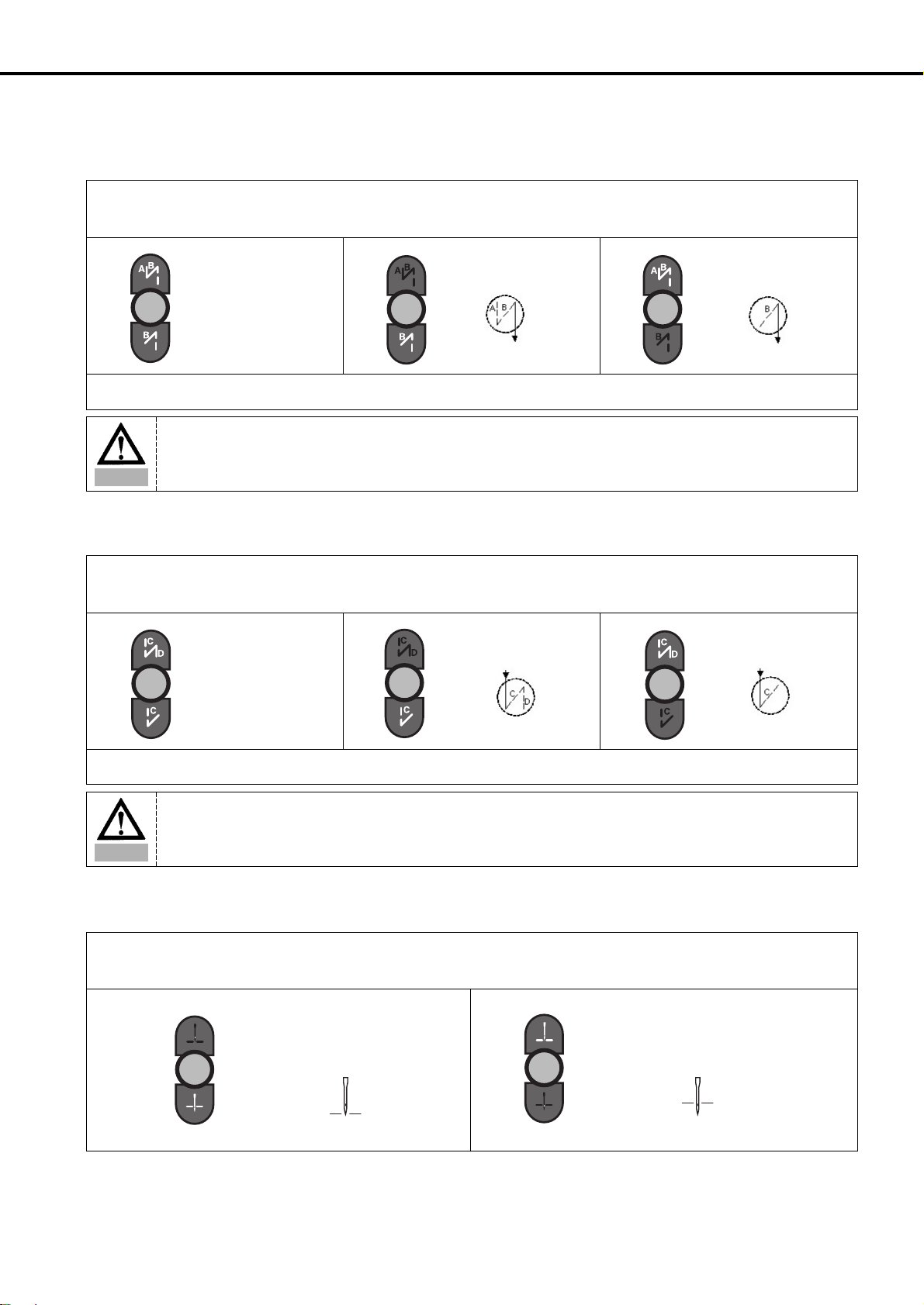
① Classification according to backtack sewing condition
※ The backtack sewing condition can be classified as follows (When A: 3 stitches, B: 3 stitches, C: 3 stitches, D: 3 stitches)
A. When one more or less stitch than the set stitch number is sewn
B. When one more or one less stitch is sewn than the programmed stitch number
Classification
Sewing condition where few backtack
Correct backtack sewing condition
Sewing condition where more
stitches are sewn backtack stitches are sewn
When sides A and B each have When sides A and B each have 3 When sides A and B each have
one less stitch sewn stitches correctly sewn one more stitch sewn
When sides C and D each have When sides C and D each have 3 When sides C and D each have
one less stitch sewn stitches correctly sewn one more stitch sewn
Start backtack
Sewing condition
End backtack
Sewing condition
Classification
B/T condition where the stitch length
Correct B/T sewing condition
comes out shorter
When the length of the last three stitches When sides A and B have 3 When sides A and B each have 3 stitches
in sides A and B have been sewn short. stitches correctly sewn.
and a half stitch (or less than one stitch) sewn
When the length of the first stitch in sides When the sides of C and D have 3 stitches
When the sides of C and D each have 3 stitches
C and D have been sewn short. correctly sewn
and a half stitch (or less than one stitch) sewn.
Start backtack
Sewing condition
End backtack
Sewing condition
Caution
The figures above show each representative sewing condition. And there may be some differences according to the
conditions of the sewing machine and it is normal that two types of conditions occur at the same time.
Page 36

36
② Start/End B/T stitch number correction method
※ The method to correct B/T stitch numbers may differ according to the user. However it is basically done in the following order.
A. When the machine sews one less or one more stitch than the programmed number of stitches.
ⓐ First, fully check the B/T sewing condition
: Commence sewing and check the current sewing condition. Refer to the figure above.
※ The example above is an explanation of when one B/T stitch number comes less than one
※ When there is more than one stitch is added or missing, you can correct the stitch number as explained above.
<Initial screen>
ⓑ If you have checked the sewing condition, first correct the stitch number that differs by
one or more stitches to the programmed stitch number.
※ Correction method for stitch numbers with more than one stitch difference
•
Program range: -6 stitches ~ 6 stitches
•
Program unit: 1 stitch
•
Method to apply correct stitch number (program using buttons A, B, C and D).
•After programming, press the and buttons simultaneously .
Ex) When there is one less Start or End B/T stitch sewn.
↓
↓
↓
Side A programmed value 3(programmed stitch number) + (3-actual stitch number sewn on side A)
Side B programmed value 3(programmed stitch number) + (3-actual stitch number sewn on side B)
Side C programmed value 3(programmed stitch number) + (3-actual stitch number sewn on side C)
Side D programmed value 3(programmed stitch number) + (3-actual stitch number sewn on side D)
a In the initial screen use buttons , , , to change it from “3 3 3 3”to “4 4 4 4.”
b After programming it to “4 4 4 4”press the button. Then press the 1/2 stitch button. You
will see the letters “bt-C”and the buzzer will ring three times and the screen will automatically
return to the initial screen.
c The changed initial screen will continue to display the wanted B/T programmed value of “3 3 3 3.”
d Recommence sewing and check the corrected stitch number
e If the corrected sewing condition continues to show more than one stitch difference, repeat steps
(a~d) and make corrections.
Caution
※ The stitch number correction value program range is between -6 stitches to 6 stitches. You cannot see the
currently applied correction value on the initial screen. If you want to see the currently applied correction value,
press the button and then the button and either check the programmed value of each side or check
items 30(side A's correction value), 31(side B's correction value), 32(side C's correction value) and 33(side D's
correction value) from Group B of the parameter.
※ If each side's corrected value has been corrected to the minimum or maximum value limit (between -6 stitches to 6
stitches) and the sewing condition is still not correct, reduce the B/T sewing speed.
※ Generally, you can correct in the manner mentioned above when there is more than one stitch difference. And you
can correct when there is less than one stitch difference with the item mentioned in the next page.
Page 37

37
B. When the machine sews less than a stitch more or less than the one programmed.
ⓐ If there are still problems with the B/T sewing condition even after correcting the stitch
numbers for more than one stitch difference based on item "A," refer to figure ①-B and
check the sewing condition again.
<Initial screen>
<When the stitch length comes out short>
<When the stitch length is less than one stitch>
ⓑ Look at the sewing condition and make the correction as follows:
※ Program range for making stitch corrections for less than one stitch:(Prog+Auto)
•
-6 stitches ~ 6 stitches
•
Program unit: 0.05 stitches (Corrections are done by dividing one stitch into 20 parts).
•
Initial program: A(00.30), B(00.30), C(00.40), D(00.40)
•
Correct stitch number application method (use C and D buttons for programming).
※※
When the stitch length comes out short(the third stitch of sides A and B/ the 1st stitch of sides C and D)
※※
<When the stitch comes out less than one stitch longer> (the last stitch of sides A and
B/ and the first stitch of sides C and D)
•
After programming, press the button and save the programmed value.
Ex) When the Start/End B/T stitch length is shorter than the programmed stitch length (by around half a stitch).
↓
↓
↓
↓
Side A program value (Currently programmed corrected value)
+ (01.00-the length of the 3rd stitch sewn in side A)
Side B program value (Currently programmed corrected value)
+ (01.00-the length of the 3rd stitch sewn in side B)
Side C program value (Currently programmed corrected value)
+ (01.00-the length of the 1st stitch sewn in side C)
Side D program value (Currently programmed corrected value)
+ (01.00-the length of the 1st stitch sewn in side D)
a In the initial screen, press the button and then also press the button.
b The screen will then go to the stitch number correction screen. Using the , buttons you
can change the length of each side (A,B,C and D) in this screen.
c If you have finished programming the new correction values to sidesA, B, C and D, press the
button and save the corrected value. If you press the button, you will return to the
initial screen. (A:00.30, B:00.30, C:00.40, D:00.40) → (A:00.50, B:00.50, C:00.75, D:00.75)
d Commence sewing and check the B/T sewing condition.
e If the corrected sewing condition still shows differences between the programmed value, the
repeat steps (a~d) and continue correction.
Side A program value (currently programmed correction value)
- the length of the extra part of the stitch sewn on side A
Side B program value (currently programmed correction value)
- the length of the extra part of the stitch sewn on side B
Side C program value (currently programmed correction value)
- the length of the extra part of the stitch sewn on side C
Side D program value (currently programmed correction value)
- the length of the extra part of the stitch sewn on side D
Caution
The shadowed part is the currently saved correct value.
Caution
※ If each side's corrected value has been corrected to the minimum or maximum value limit (between -6 stitches to 6
stitches) and the sewing condition is still not correct, reduce the B/T sewing speed.
※ Generally, you can correct for when there is more than one stitch difference with item A. However, with item B, you
can correct when there is either more or less than one stitch difference.
※ Make sure to press the button and save the programmed value when you finish programming sides A, B, C
and D's new correction value.
Page 38

38
① The inertia tuning function enables the machine to save the gain value of the motor
that matches the loaded inertia. If you simultaneously press buttons and ,
you will see the inertia tuning screen. Then, you will see the words "TUNE" blinking.
② When the screen changes, you must press the pedal until the buzzer rings. If you
release the pedal before the buzzer rings the inertia tuning won't be completed.
Therefore, you must press on the pedal until the buzzer rings.
(When doing inertia tuning, the sewing machine will operate and stop 10 times).
③ When inertia tuning is completed, the buzzer will ring and it will automatically return
to the initial screen.
4) Method of Use: Inertia Tuning Function
<Inertia tuning initial screen>
<Initial screen>
Caution
Inertia tuning can only be carried out when the controller is attached to the sewing machine for the first time and when
the sewing machine does not accelerate or decelerate quickly.
Page 39

39
① Attach the edge sensor box (ass’y) connected to the edge sensor to the table.
② Link the edge sensor connector to the switch connector .
① Attach the edge sensor bracket to the sewing machine head as in the figure.
② Insert the edge sensor into the attached edge sensor bracket.
5) How to Use Edge Sensor
(1) Installing the Edge Sensor
< KM-235,250 > < KM-750,790 >
①+5V
②+5V
③ L LED
④ R LED
⑤ L S/W
⑥ R S/W
⑦ GND
⑧ 4/4 (N.C)
⑨ 3/4 (N.C)
⑩ 2/4 (N.C)
⑪1/4 (N.C)
⑫ (N.C)
[ Shape of pin ] [ No. of pin ]
Page 40

40
(2) Edge Sensor Setup
① While the button is being pressed, turn on the power.
② While the switch is being pressed, press button to enter the Parameter C
Group.
③ Use the and buttons to set the Parameter C Group at 52. Use the and
buttons to change the dalue of 2 to 12.
④ After going through the above processes ~ , press to save the new value.
Press the button to exit the parameter setup mode.
⑤ After under going the above processes ~ , press the button. When the LED is
on, the sensor is working.
Pressing the edge sensor button makes sewing motion stop when the sewing material edge is detected. For proper
implementation of the function, have a thorough understanding of “Section (4) Use of Detailed Edge Sensor
Functions” in the manual before use.
Caution
⇒
(3) Edge Sensor Sensitivity Setup
① Without a sewing material located under the sensor, set the operating mode on the
back of the sensor at L.ON.
② Press the button and the lamp blinks. Place a sewing material under the sensor
and check if the STB lamp (amber) in front of the sensor blinks.
③ In the event that the STB lamp(amber) in front of the sensor is not turned on, change
the operating mode on the back of the sensor to D.ON and repeat the process
again.
(The reason of the lamp turned off is the edge sensor reacts depending on sewing
material types.)
④ After undergoing the above processes ~ , adjust the SENS volume on the sensor
front to make sure that the OPL lamp(Red) remains turned off when the sewing
material is below the sensor and that the OPL lamp(Red) blinks when the sewing
material is not below the sensor.
At this time, the blinking of the STB lamp(amber) does not matter.
Page 41

41
(4) Use of Detailed Edge Sensor Functions
① While the button is being pressed, press the button to enter the Parameter Group
A. (Entry into the parameter group is allowed only after trimming.)
② Use the and buttons to set the parameter numbers subject to revision. Use the
and buttons to change parameter values.
③ Change each parameter value and save the new value by pressing the button.
A-Group
Function
41
42
43
Sensor type select
After the edge is sensed, set the stitch
count to proceed
After the edge is sensed, set the sewing
speed for the stitches.
0
3[stitches]
1000[rpm]
0 : When the edge is sensed, 5[V] output(Active High)
1 : When the edge is sensed, 0[V] output(Active Low)
0~255[stitches]
20~2000[spm]
1[stitches]
10[spm]
Initial Value
Scope Stage
1. Note that a new value is not saved without pressing the button after parameter value reset.
2. If the system is initialized, all data is recovered back to the initial values.
Caution
(5) Edge Sensor Motion
(6) Deactivating Edge Sensor
① Press the button to activate the edge sensor.
② If the edge sensor is activated, when the sewing material edge is detected, the sewing
is suspended (distance between the needle and the sewing material edge: some
20[mm]).
③ When the sewing is suspended as in ②, move the pedal from “Neutral” to “Forward”
and then the sewing is resumed at the stitch count set at Parameter A-42 at the speed
set at Parameter A-43.
④ After completing the process ③ and conducting trimming (pedal backward), the
backtack sewing for finish (in the case where the backtack lamp is blinking) and
trimming are performed in order.
① Press the button to turn off the lamp and then the edge sensor is deactivated.
⇒
⇒
Page 42

42
Save
Select the Model
Desired
Move to B-56Parameter B Group Initial Screen
Program Enable
6) Motor Controller Setting
(1) Controller Setting by Machine Type
Classification
1
2
3
SC-7300 Series
SC-7500 Series
SC-7310 Series
88
124
125
Parameters are set according to the
ordered specifications before
machine's shipment from the
factory.
Machine Type Set Value for Parameter B-56 Model Remarks
※ Model Number Setting
[Note]
① Before the product is shipped out from the factory, all settings are completed in line with the machine type ordered.
② In case where the controller which is different from the ordered specifications is installed to the chain-type machine:
⇨ Set the value of parameter B-56 according to the concerned machine type.
⇨ Depending on the program version of controller, it may not be applicable to some machines. See the following to make the
proper setting according to the machine type.
※ Version display
When the power is turned on, the CPU version is displayed as below on P/U for a moment, and then the screen moves to the initial
screen ("3333").
This is an old version where the CPU version is not displayed.
“POWER ON”+ + or
⇨
or
⇨⇨
⇨⇨
Classification Fortuna Series III(CPU version 11) Fortuna Series IV(CPU version 7)
Program Unit
(P/U)
Handy Controller
⇨ ⇨
Page 43

43
(2) In case where the top thread trimming device is installed
Make a setting based on the check points below to ensure proper operation of the top thread trimming device when the top
thread trimming device is installed.
① Make the setting as below depending on the program version of the controller .
② Modification of the sequence of Parameter B-55
Using the external program unit
※ Use and buttons when changing the value of sequence.
※ Use and buttons to move to the next sequence.
Program version
1
2
S-III version "11" or above
S-IV version "7" or above
Lower than S-III version "11”
Lower than S-IV version "7"
Set the value of Parameter A-73 at "1"
Modify the trimming sequence of Parameter B-55.
Setting
Move to B-55Parameter B GroupInitial Screen
“POWER ON”+ + or
⇨⇨⇨
80[ms]Lapsed Time: Unit-1[ms]
T/T Sol. “ON”
Sequence Start
⇨⇨⇨⇨
W/P Sol. “ON”
66[ms]Lapsed Time: Unit-1[ms]
T/T Sol. “OFF”
⇨⇨⇨⇨
Sequence End
W/P Sol. “OFF”
0[ms]
Lapsed Time: Unit-1[ms]
⇨⇨⇨⇨
Sequence Save
⇨
Page 44

44
How to use the imbedded handy controller
[Note]
When modifying the sequence by using the handy controller, the change in the sequence number is not displayed, so more care
should be exercised in conducting the modification.
※ Use and buttons when changing the value of sequence.
※ Use and buttons to move to the next sequence.
SequenceB-55Group B
Program Start
+
⇨⇨⇨
80[ms]Lapsed Time: Unit-1[ms]
T/T Sol. “ON”
Sequence Start
⇨⇨⇨⇨
W/P Sol. “ON”
66[ms]Lapsed Time: Unit-1[ms]
T/T Sol. “OFF”
⇨⇨⇨⇨
0 [ms]Sequence End
W/P Sol. “OFF”
Lapsed Time: Unit-1[ms]
⇨⇨⇨⇨
Sequence Save Group B
⇨⇨
Page 45

45
(3) Trimming Sequence of Chain-type Machine
When installing the controller which has an older program version, see the following and correct the trimming sequence.
01 --80 Sequence Start
02 --83 T/T Solenoid "ON"
03 --B0
80[ms] of Time Lapse
04 80
05 --9A T/T Solenoid "OFF"
06 --B0
66[ms] of Time Lapse
07 66
08 --84 W/P Solenoid "ON"
09 --B3
1[s] of Time Lapse
10 10
11 --9B W/P Solenoid "OFF"
12 --00 Trimming Sequence End
•
• --00
•
64 --00 Sequence Close
Number Command
Data Part
Explanation
1st 2nd 3rd
Work Flow Program Code
Start of Sequence
End of Sequence
T/T Solenoid “ON”
Wait for 80[ms]
T/T Solenoid “OFF”
Wait for 66[ms]
W/P Solenoid “ON”
Wait for 1[s]
W/P Solenoid “OFF”
[Note]
⇨
When installing the top thread trimming device, change the trimming sequence value in No. 09 from B3 to B0 and the value in
No. 10 to "0".
⇨
If the program version is S-III("11") and S-IV("7") or above, set the value of A-73 at "1".
Page 46

46
① Supporting existing pattern ■ If Parameter A-76 is set at (0) for Disable, the existing pattern functions can be used as same.
functions
② Max. Pattern Value ■ Up to 15 patterns can be used.
③ How to set ■ Parameter A-76 can be set in two ways.
A. Setting by parameter adjustment
a. Press + to move to Parameter Group A.
b. Use and to move to A-76.
c. Use and to change a set value.
d. Press to save a set value and press to revert to
the initial screen.
B. Setting with hotkeys
a. Press + to move to Parameter Group A.
b. Use and to change a set value.
c. Press to save a set value and then press to
revert to the initial screen.
④ Considerations
■ When using hotkey functions, press PATTERN to turn off LED before use.
■ When using extended pattern functions, make sure of using No. 1 pattern.
7) Advanced Pattern Sewing Functions
(1) Related Parameters
Parameter No Parameter Name Set Value
A-76 Pattern Advanced Function 0(Disable) / 1(Enable)
(2) Features of Function
Item Description
Page 47

47
(3) Detailed Functional Setting and Use
Sequence
① Enable the Pattern Extension ■ Set A-76 at 1, and use hotkey functions to amend the set value from
Function 0 to 1.
② Check No. 1 pattern setting ■ Check if Pattern No. 1 LED is on.
- In the event that LED is on for other patterns, press No. 1 button
to select.
■
/
buttons: Move around patterns from 1 to 15 to select a desired
pattern.
■
/ buttons: Enter the stitch count into the pattern number currently
marked.(The set value is automatically saved)
■ “Yes” is displayed on the screen.
④ When one among set patterns is used ■ Use and buttons to move to a desired pattern and begin sewing.
■ Press button to turn on CHAIN LED, and then begin sewing.
- Start sewing from No.1.
■ Possible to use and buttons to change the start position.
■ During the chain sewing, if an encountered pattern’s stitch count is zero
(0), it is automatically converted to No. 1 pattern and sewing continues.
⑥ Notice ■ When using the pattern extension function, and buttons indicate
the pattern number currently under work.
■ To release the function, press button to turn off PATTERN LED
and set A-76 at zero(0).
No.10 : A
No.11 : B
No.12 : C
No.13 : D
No.14 : E
No.15 : F
Description
Remarks
Set 11 stitches for No. 1 pattern.
Set 10 stitches for No. 14 pattern.
③ Enter the set values for pattern stitch
count as many as desired among 15
patterns.
⑤ In the event of conducting chain
sewing in the set pattern order
Page 48

48
8) Automatic Change Function of Twin Needles (applicable to the models supporting twin needles)
(1) Related Parameters
Parameter No Parameter Name Set Value
A-77 Setting automatic change function for twin needles
0(disable)
1(enable)
E-0 ~ E-135 Detailed settings for automatic change of twin needles See Parameter Group E.
(2) Features of Function
Item Description
① Supporting existing pattern ■ If Parameter A-77 is set at (0) for Disable, the existing pattern functions can be used as same.
functions
② No. of pattern in use ■ Pattern No. 2, 3, 5 requiring changes can be set.
③ Use of Functions ■ Set A-77 at 1 and set Parameter Group E’s data.
Caution
From 100 to 135, they are redundantly displayed from 00 to 35.
Caution
If set values are changed without through understanding of Parameter Group E set values and “(3) Example of
Changes for Each Step,” mechanical breakdown or physical damage may result. Therefore users are
recommended to have a thorough understanding before use.
Page 49

49
(3) Example of Changes for Each Step
■ Example of No. 2 pattern (3 sides)
Step
Parameter
#
Description Details Pedal Start Frequency Remarks
STEP 1 E-01 ■ Stitch count entry for side 1 Pattern speed
STEP 2 E-02 ■ Select each change at the beginning 0: No setting
of the first corner 1: Left Sol. motion
2: Right Sol. motion
STEP 3 E-03 ■
Enter stitch count at the beginning of the first corner
SBT speed (A-7)
STEP 4 E-04 ■ Enter stitch count at the end of the first corner SBT speed (A-7)
STEP 5 E-05 ■ Select each change at the end of the first corner 0: No setting
1: Left Sol. motion
2: Right Sol. motion
STEP 6 E-06 ■ Enter stitch count for side 2. Pattern speed
STEP 7 E-07 ■ Select each change at the beginning of the 0: No setting
second corner. 1: Left Sol. motion
2: Right Sol. motion
STEP 8 E-08 ■
Enter stitch count at the beginning of the second corner.
SBT speed (A-7)
STEP 9 E-09 ■ Enter stitch count at the end of the second corner. SBT speed (A-7)
STEP 10 E-10 ■ Select each change at the end of the 0: No setting
second corner. 1: Left Sol. motion
2: Right Sol. motion
STEP 11 E-11 ■ Enter stitch count for side 3. Pattern speed
STEP6
: Stitch count for side 2
STEP 7
: Set each change
when corner 2 begins
STEP 8
: Stitch count when
corner 2 begins
STEP 5
: Set each
change when
corner 1 ends
STEP 4
: Stitch count
when corner 1
ends
STEP 2
: Set each
change when
corner 1 begins
STEP 3
: Stitch count
when corner 1
begins
STEP 1 : Stitch count for side 1
STEP 10
: Set each
change when
corner 2 ends
STEP 9
: Stitch count
when corner 2
ends
STEP 11 : Stitch count for side 3
1
When a pedal is stepped,
automatic execution of
Step 1 to 3 takes place.
2
When a pedal is stepped,
automatic execution of
Step 4 to 8 takes place.
3
When a pedal is stepped,
automatic execution of
STEP 9 to 11 takes place.
Page 50

50
1) Names of Each Part in the Simple Operation Unit
2) Simple Program Unit Method of Use
(1) Initializing
SIMPLE OPERATION UNIT PART NAMES AND METHOD OF USE
99
※ Simple operation unit is attached in the front of the control box and used when there is no program unit panel.
4-Digit Displayer
Start B/T Programming Displayer
A Button Switch
End B/T Programming Displayer
B Button Switch
Thread Trimming and Wiper Programming Displayer
Button Switch for Program Changes
Presser Foot-lift Up Stop and Down Stop Programming Displayer
D Button Switch
Needle Plate Up Stop and Down Stop Programming Displayer
C Button Switch
This function is used when the user randomly corrects the programmed value and forgets the initial programmed value.
Turn the power on by simultaneously pressing the buttons , and , .
Caution
•When you initialize, you change all the original values that the sewing machine had when it was manufactured in the factory.
Initialize only when absolutely necessary.
•When initializing, you must run the motor for more than 5 seconds at the speed of 1000RPM in order to make the synchronizer
to work properly.
Page 51

51
(2) Programming the Start B/T Sewing Conditions with Button
This button is used when the user wants to prevent threads from loosening at the end of the sewing work. If the user presses this button
in sequence, the location on the lights will change as shown in the figures below. This button offers the following three functions.
Use the A, B button to program the number of B/T stitches in the 4-digit displayer.
When sewing starts, B/T sewing does not
operate.
When sewing starts, B/T sewing can be done
with the button.
When sewing starts, B/T sewing can be done
with the button.
(3) Programming the Start B/T Sewing Conditions with Button
This button is used when the user wants to prevent threads from loosening at the end of the sewing work. If the user presses this button
in sequence, the location on the lights will change as shown in the figures below. This button offers the following three functions.
Use the C, D button to program the number of B/T stitches in the 4-digit displayer.
When sewing starts, B/T sewing does not
operate.
(4) Programming the Needle Plate Position when Sewing Stops with Button
When you turn the power on, one of needle plate's up stop and down stop lights in the simple operation unit will always be on. If you
press the button you can select the stopping location.
If the machine stops while sewing, the needle
plate makes an up stop.
If the machine stops while sewing, the needle
plate makes a down stop.
When sewing starts, B/T sewing can be operated
with the button.
When sewing starts, B/T sewing can be operated
with the button.
Caution
Be aware that if the end B/T stitch number is set to '0' in the 4-digit displayer, the user will be unable to operate start
B/T sewing.
Caution
Be aware that if the end B/T stitch number is set to '0' in the 4-digit displayer, the user will be unable to carry out start
B/T sewing.
Page 52

52
(5) Programming the Presser Foot-lift Location when Sewing Stops with the Button
When you turn the power on, one of presser foot-lift's up stop and down stop lights in the simple operation unit will always be on. If you
press the button you can select the stopping location.
If the machine stops while sewing, the
presser foot-lift makes an up stop.
If the machine stops while sewing, the
presser foot-lift makes a down stop.
(6) Programming the Automatic Thread Trimmer and Wiper Movements with the Button
This button programs the automatic trimmer and wiper after sewing. If the user presses this button in sequence, the location on the lights
will change as shown in the figures below. This button offers the following three functions.
Automatic trimmer and wiper are not
operating.
Only the automatic trimmer is operating
Both the automatic trimmer and wiper are
operating
① Press the appropriate button for 0.5 seconds for the place you wish to program the new
B/T stitch value. The light will blink in that place.
•Programming buttons for number of start B/T stitches:buttons ,
•Programming buttons for number of end B/T stitches:buttons ,
② If the number is blinking, you can change the programmed value by pressing the
appropriate button.
(Ex:If you press the A button for 0.5 seconds, the first number in the screen will blink).
③ If programming is completed, press the same button for 0.5 seconds once more and
you will return to the initial screen.
(Ex : Changing the value of A, B, C, D from 3, 3, 3, 3 to 4, 4, 4, 4)
(7) Programming the Start and End B/T Stitches
<Initial Screen>
<When the button A has been pressed for 0.5 seconds>
Caution
Be aware that if you don't press the button for 0.5 seconds, the screen will not return to the B/T stitch programming
screen but will remain in the sewing conditions program change (items 1~4 functions) section.
Page 53

53
① If you press the button for 0.5 seconds, you will see the screen that enables you
to change the sewing speed. If you press the same button again for 0.5 seconds, you
will see the screen that enables you to change the rotating direction. If you press the
button one more time, you will return to the initial screen.
(Initial screen → Speed programming screen → Rotating direction programming
screen → Initial screen)
② If you want to change the sewing speed, press the button. After seeing the speed
programming screen, press buttons and to program the speed you want.
③ If you want to program the rotating direction, press the button to see the
rotating direction programming screen, then press buttons and to change
the rotation to the direction you want.
•reverse direction : dir 0 •normal direction : dir 1
(8) Sewing Speed and Rotating Direction Programming Method
① To change the parameter's detailed items, press the and buttons
simultaneously and return to the parameter detailed item's initial screen.
② If you see the “PrEn" screen, select a parameter group using buttons A~D.
• button:A group, button:B group
• button:C group, button:D group
③ After selecting the group you want, use buttons and to select the specific
item you want.
•Ex: Select No. 2 item of Group A (Limiting the maximum sewing speed)
④ If you selected the specific item you wanted, press button . The value you
selected will then appear on the screen.
•Ex : The current maximum sewing speed 400RPM.
⑤ Using the buttons and , change the current programmed value to another
value.
•Ex : Change the maximum sewing speed from 4000RPM to → 3000RPM
(9) Method to Change Parameter Specific Items
<parameter specific item initial screen>
<Initial screen for group A> <Initial screen for group B>
<Initial screen for group C> <Initial screen for group D>
Caution
Be aware that if you don't press the button for 0.5 seconds, the screen will not return to the B/T programming screen
but will remain in the sewing conditions programming screen (Items 1~4 functions).
Page 54

54
(10) Start and End B/T Stitch Number Correction Method
⑥ If you completed your selection, press the to save the value you chose.
⑦ You can change other specific items of the parameter in the same manner.
①The inertia tuning function is to find the motor's gain value that match the weights
inertia. Press buttons and simultaneously to return to the initial screen of
the inertia tuning.
② If the initial screen comes on, press the pedal until you hear the buzzer ring.
(During inertia tuning the sewing machine will operate and stop 10 times).
③ If the inertia tuning is completed, the buzzer will ring and the initial screen will come
on at the same time.
(11) Method of Use of the Inertia Tuning Function
<Inertia tuning initial screen>
<Initial screen>
① Corrections in the initial screen are the same as those in item (13) of the program unit
manual "Correcting method for when the B/T number differs by one stitch"
a. Check the present sewing condition.
b. Change the value of the part that needs correction (use
, , ,
buttons)
c. Save the programmed value(press the and buttons simultaneously).
→ You will go to the “bt-C”screen. The buzzer will sound three times and you will
return to the initial screen
② When making corrections of less than one stitch use items 30~33 of parameter Group
B and will correct to stage 0.05.
※ For detailed B/T stitch number correction method, refer to the section 3) of the Program Unit manual.
↓
↓
↓
Caution
•Be aware that if you changed the specific items of the parameter and didn't press the button, the changed
value will not be saved.
•If you change the parameter specific items carelessly, this may cause breakdown or physical damage to the
machine. Therefore, the user must be well-trained before changing items in the parameter group.
Caution
Inertia tuning is carried out only when the controller is attached to the sewing machine for the first time and when the
sewing machine is unable to accelerate or decelerate quickly.
Page 55

55
1) Basic Functions of the Fortuna Series 5 Full Function Software
(1) Initializing
(2) Sewing Machine Up/Down Stop Location Automatic Recalling Function
When first purchasing the controller, if the user steps on the pedal for 5 seconds and runs the motor before beginning the sewing work, the
machine will automatically remember the sewing machine's up/down stop location. However, when using a synchronizer this step is not
necessary.
(3) Method of Use and Functions of the Program Unit and the General Control Box's Simple Operation Box.
When there is a program unit(P/U), use it to program or change all the functions of the machine. When there is no program unit, use the
general control box operation panel to program or change all the functions of the machine.
※ For detailed information on the method of use of program units and simple operation panel refer to the explanation in the last section.
(4) Function Parameter
FORTUNA SERIES 5 FULL FUNCTION SOFTWARE METHOD OF USE
1100
This function is used when the user randomly changes the parameter's programmed value, and forgets the original program contents.
Method of initializing: Turn the power on by simultaneously pressing the buttons in the figure above which are the start B/T button + end B/T
button + needle plate up/down stop button.
Caution
•If you initialize, all the changes made by the user are changed to the original values programmed when the
machine was delivered from the factory, therefore only change the value if absolutely necessary.
•After initializing, rotate the machine for 1000RPM or more for approximately 5 seconds. You must make the
machine remember the location of the FILM.
Parameter group Functions
① Group A General functions of the sewing machine
② Group B All types of output, Full-on Time/PWM Duty, checking input/output operations, sewing machine models and
thread trimming sequence programming
③ Group C Pedal acceleration/deceleration curve, slow starting speed and input/output port change related parameters
④ Group D All types of gain parameter related motor control
⑤ Group E Automatic Change Function of Twin Needles
Related Parameters
※ If the specific items of the parameter are changed carelessly, they could cause breakdown or damage the machine. Therefore the
user must be well-trained before using it.
Page 56

56
2) Fortuna Series 5 Full Function Software Specific Parameters
(1) Group A Parameter: General functions of sewing machine
No. Function StepRange
Initial value
1 Minimum speed of pedal (limit of sewing machine's minimum speed) 200spm 20~510 2spm
2 Maximum speed of pedal (limit of sewing machine's maximum speed) 4000spm 40~9960 40spm
3 Thread trimmer speed 300spm 20~510 2spm
(Sewing machine speed from beginning to end of thread trimming when using CAM type)
4 Program Unit + 1 stitch speed ( Key's performance speed) 100spm 20~510 2spm
5 Lifting of needle plate with button A, dropping speed ( 's performance speed) 300spm 20~510 2spm
6 Pedal degree of acceleration (Pedal Curve) 255 1~255 1
( ;When the maximum speed is put in 255 steps)
7 Start Back-Tack Speed 1700spm 20~2000 10spm
8 End Back-Tack Speed 1700spm 20~2000 10spm
9 Thread trimming operation time 100ms 4~1020 (When doing an aging test,
(The A24 used in PNEUMATIC = must be 1) the value is equal to the running time)
(The Solenoid operation time)
10 Tension release operation time (The A24 used in PNEUMATIC = must be 1) 200ms 4~1020 (When doing an aging test, the value
is equal to the thread trimming time)
11 Tension release time (In CAM type, the used A24 = must be 0) 255 0~255
(In CAM type, the tension release is the value of the moving CAM angle)
12 Waiting time for the next operation after thread trimming 4ms 4~1020
(This is the delaying time to carry out the next operation after thread trimming is finished)
13 Wiper operation time (Wiper Solenoid operating time) 48ms 4~1020 4ms
14 Waiting time after wiper operation(presser foot-lift etc.) 40ms 4~1020 4ms
15 Automatic presser foot-lift delaying time 100ms 4~1020 4ms
16 Automatic presser foot- lift maintaining time 300×0.1sec 5~1000 0.5sec
(After programmed time the presser foot-lift is automatically released)
17 Automatic presser foot-lift drop waiting time for next operation 100ms 4~1020 4ms
(The delaying time, or the time that the foot-presser lift is maintained,
the pedal is started until the presser foot-lift drops and the sewing machine is started)
18 Selection for automatic foot-presser lift after thread trimming 0 0/1 1=lift selection
0=step backward thread trimming
19 Selection for pedal thread trimming position 0 0/1/2 0=step backward thread trimming
1=1 step backward thread trimming
2=thread trimming at neutral position
20 The maximum sewing speed for the KM-1060BL-7 presser foot-lift 2000spm 200~2000 10spm
with mutual crossing quantity of 4.8 ~ 7.0[mm]
21 Delaying time for complete release of KM-1060BL-7 B/T Solenoid 200ms 4~1020ms 4ms
22 Select to operate 2 start B/T 0 0/1 Choose between 1 or 2
()
23 Select to operate 2 end B/T 0 0/1 Choose between 1 or 2
()
24 Selection of thread trimming conditions 0 0/1/2 0=CAM type machine
(selection according to sewing machine type) 1= thread trimming after up-stop
2=thread trimming after low-stop
25 Whether or not to use default sequence when A24 = 1 0 0/1 0=B-55 exclusive sequence is used
(This is a sequence determined on A9,A10 value) 1= default sequence is used
Caution
If the specific items of the parameter are changed carelessly, they could cause breakdown or damage the machine.
Therefore, the user must be well-trained before using it.
Page 57

57
No. Function StepRange
Initial value
26 Selection of B/T Solenoid operation position 0 0/1 0= lower position
1= upper position
27 Setting the maximum sewing speed of the machine according to ? ? program P1xx → P2xx → P3xx
presser foot-lift height of the KM-1060BL sewing machine. in order
Less than P1xx:3500[spm]
Less than P2xx:3000[spm]
Less than P3xx:2500[spm]
More than P3xx: A20[spm]
28 Needle bar’s automatic stop at the highest position 0 0/1
29 Pedal analog filtering difference 15 1~200 1
30 When using an angle 2-needle, select the semi-automatic corner operation 0 0/1 1=selection of semi-automatic
31 Speed when selecting a semi-automatic corner 200spm 20~2000 10spm
(parameter used only when used after selecting number 30)
32 After selecting the left needle the first sewing stitch 3 stitches 0~255 1 stitch
(parameter used only when used after selecting number 30)
33 After selecting the left needle the second sewing stitch 3 stitches 0~255 1 stitch
(parameter used only when used after selecting number 30)
34 After selecting the right needle the first sewing stitch 3 stitches 0~255 1 stitch
(parameter used only when used after selecting number 30)
35 After selecting the right needle the second sewing stitch 3 stitches 0~255 1 stitch
(parameter used only when used after selecting number 30)
36 Maintaining time for the left/right needle solenoid 450×0.1sec 50~1000 0.5sec
(After the programmed time the solenoid is automatically released)
37 NOT USED
38 NOT USED
39 Stopping function during AUTO mode and while pedal is neutral 1 0/1 0=does not stop
1=stops
40 Selection of type of N-stitch Sensor 0 0:active high 1:active low
41 The number of stitches done after the N-stitch Sensor has finished sensing. 3 stitches 0~255 1 stitch
(After sensing, it will sew the programmed number of stitches and stop)
42 N-stitch sewing speed 1000spm 20~2000 10spm
43 Selection of One Touch function → replaced by AUTO Key function 0 0/1 1=Auto Mode
(Used in the sewing mode that uses the auto function)
44 Selection of One Touch function → replaced by AUTO sewing mode programming 0 0/1 1=One-Shot Mode
(If there is no thread trimming signal when selected, sewing will continue even if user releases pedal)
45
One-Shot sewing speed → When using AUTO function, it is programmed with the speed Up/Dn Key
2000spm 40~9960 40spm
46 N-stitch sewing mode selection → a sewing mode that inputs a sensor signal 0 0/1 1=N-stitch Mode
in the edge sensor port and uses it as an edge sensor
47 Selection of pre-stitch function (When selected it will perform only 0 0/1 1=selection
the programmed stitches before the actual sewing work starts)
48 Pre-stitch number of stitches 3 stitches 0~255 1 stitch
49 Pre-stitch speed 2000spm 20~2000 10spm
50 Selection of start B/T operating conditions 0 : B/T stop function selected
( 0 : if pedal is released during back tack, it will stop) 1 1 : B/T work completion
( 1 : if pedal is released during back tack, the work will still be completed) 2 : B/T exact stitch performance
( 2 : it will perform the exact amount of back tack stitches)
51 Selection of end back tack performance condition 0 0/1 1= exact stitch performance
(It will perform the exact amount of stitches for end back tack )
52 Back tack initial first stitch speed during back tack exact performance 200spm 20~1000 10spm
Caution
If the specific items of the parameter are changed carelessly, they could break down or damage the machine, so the
user must be well-trained before using it.
Page 58

58
No. Function StepRange
Initial value
53 Change between B/T and switch with buttons A or B during sewing 0 0/1 1= Select with button B
54 Selection of button A function 2 0 : Only B/T operates
1 : Lift and drop needle plate with one movement.
2 : Lift needle plate with one movement.
Drop needle plate with two movements
3 : Slow performance when stopped
(1/2 stitch speed)
55 Selection of Button B function 0 0 : B/T delete insertion
1 : Lift and drop needle plate with one movement
2 : Slow performance when stopped
(1/2 stitch speed)
3 : Only B/T operates
56 Selection of speed during manual back tack during sewing 0 0/1 0 : current sewing speed
1: initial reverse speed
57 NOT USED
58 Thread Trimming Sequence Selection of SunStar Chain Stitch Machine 1 0/1 1
59 Thread Trimming Sequence Selection of other Company chain Stitch Machine 0 0/1 1
60 Selection of reverse rotation after trimming 0 0/1 1:selection of reverse direction
61 Reverse rotation distance when selecting reverse rotation after thread trimming 20degree 0~250 1degree
62 When machine stops fix pulley (When machine stops fix the motor by force) 0 0/1 1: fix when machine stops
63 Power to fix the A number 62 Pulley 40 10~100 1
64 Distance recovered after fixing A number 62 Pulley and rotating it by force 20degree 10~100 1degree
65 Select the motor rotating direction ( )
1 0/1 1 : clockwise
0 : counterclockwise
66 Target speed : If this speed is reached or passed, a signal saying 1000spm 40~9960 40spm
“Target speed has been reached”will appear.
(As an interior Port it is alloted and used in the ‘C’GROUP-Default is auxiliary)
67 Delay start setup 0 0/1 0=normal start
1=Delay start
68 Delay start time duration setup 3 3~250 1×100[ms]
69 Setup of needle bar's stop at the lowest position after trimming when the 0 0/1 0=disabled
pedal is pressed 1=enabled
70 Setup of the duration of needle bar's stop at the lowest position after 100 100~250 1[ms]
trimming when the pedal pressed
71~75 Not Used -- -
76 Setting pattern sewing extension 0 0/1 0 : No pattern extension
1 : Pattern extension
77 Automatic changes of twin needles 0 0/1 0 : Teach stitch not used
1 : Teach stitch used
78 Start Backtack ON Duration 4[ms] 4~1020[ms]
79 Start Backtack OFF Duration 4[ms] 4~1020[ms]
80 End Backtack ON Duration 4[ms] 4~1024[ms]
81 End Backtack OFF Duration 100[ms] 4~1020[ms]
82 Stitch width reduction during backtacking 0 0/1 0=disabled
1=enabled
83 Not Used
84~87 Not Used -- -
88 Automatic PF lift and left/right needle solenoid lift 1
0 : Enable(in the event of using an electronic solenoid)
Enable/disable the solenoid OFF function after maintain
1 : Disable(in the event of using a pneumatic solenoid)
89 Upon trimming for a chain-type model, enable/disable the needle auto lift. 0 0/1
0=disabled
1=enabled
clockwise /counterclockwise
CCW
CW
Caution
If the specific items of the parameter are changed carelessly, they could break down or damage the machine, so the
user must be well-trained before using it.
4[ms]
(Parameter run when the Backtack
accuracy function is used)
Page 59

59
(2) Group B Parameter : All types of output, Full-on Time/PWM Duty, checking input/output operations, sewing
machine models and thread trimming sequence programming.
※ These are functions not used by general users and must be regulated by an A/S technician.
No. Function StepRange
Initial value
※ Items No. 30~33 : These are the items that make the number of stitches match when back tack number of stitches do not match.
※ Solenoid Duty Ratio : The power that holds and maintains the solenoid.
Solenoid initial full on time : The time it takes to pull the solenoid to the maximum in the outset.
1 Back Tack Solenoid Initial Full On Time 1020ms 4~1020 4ms
2 Presser Foot-Lift Solenoid Initial Full On Time 200ms 4~1020 4ms
3 T/T Solenoid Initial Full On Time 100ms 4~1020 4ms
4 Wiper Solenoid Initial Full On Time 100ms 4~1020 4ms
5 Tension Release Solenoid Initial Full On Time 100ms 4~1020 4ms
6 Left Solenoid Initial Full On Time (For Twin Needle) 100ms 4~1020 4ms
7 Right Solenoid Initial Full On Time (For Twin Needle) 100ms 4~1020 4ms
8 Auxiliary Solenoid Initial Full On Time 100ms 4~1020 4ms
9 Left LED Initial Full On Time (For Twin Needle) 100ms 4~1020 4ms
10 Right LED Initial Full On Time (For Twin Needle) 100ms 4~1020 4ms
11 Needle plate up-stop signal Initial Full On Time 100ms 4~1020 4ms
12 Needle plate down-stop signal Initial Full On Time 100ms 4~1020 4ms
13 Signal notifying motor running Full On Time 100ms 4~1020 4ms
14 Signal notifying target speed achieved Full On Time 100ms 4~1020 4ms
15 Back Tack Solenoid Duty Ratio 50% 0~100 10%
16 Presser Foot-Lift Solenoid Duty Ratio 20% 0~100 10
17 Thread Trimming Solenoid Duty Ratio 100 0~100 10
18 Wiper Solenoid Duty Ratio 100 0~100 10
19 Tension Release Solenoid Duty Ratio 100 0~100 10
20 Left Solenoid Duty Ratio (For Twin Needle) 50 0~100 10
21 Right Solenoid Duty Ratio (For Twin Needle) 50 0~100 10
22 Aux Solenoid Duty Ratio 100 0~100 10
23 Left LED Duty Ratio (For Twin Needle) 100 0~100 10
24 Right LED Duty Ratio (For Twin Needle) 100 0~100 10
25 Signal for up stopping needle Duty Ratio 100 0~100 10
26 Signal for low stopping needle Duty Ratio 100 0~100 10
27 Signal notifying motor running Duty Ratio 100 0~100 10
28 Signal notifying target speed reached Duty Ratio 100 0~100 10
29 NOT USED
30 Start Back Tack A number of stitches correction value 00.30 6~6 0.05 Stitch
31 Start Back Tack B number of stitches correction value 00.30 6~6 0.05 Stitch
32 End Back Tack C stitch correction value 00.40 6~6 0.05 Stitch
33 End Back Tack D stitch correction value 00.40 6~6 0.05 Stitch
34
Selection for maintaining reverse solenoid movement when thread trimming (C Only B/T)
0 0/1 1=reverse direction maintained
35 Programming count condition 0 0/1 0=counter used
(program whether or not automatic counter will be operated)
1=automatic counter after thread trimming
36
When automatically counting, select Up/Down count after thread
1 0/1
1=Up COUNT
trimming (thread trimming function must be enabled) 0=DOWN COUNT
0=buzzer rings, sewing is allowed
37 When count in completeded, the next operation is programmed 0 0/1/2
1=buzzer rings, sewing is not allowed
(If you press the Prog Key, set up is cancelled)
2=No buzzer ring, sewing is allowed
38 When count is completed, select the counter auto clear/preset 0 0/1
1=AUTO
CLEAR/PRESET
39 NOT USED
Caution
If the specific items of the parameter are changed carelessly, they could break down or damage the machine, so the
user must be well-trained before using it.
Page 60

60
No. Function StepRangeInitial value
※ Items No. 40~53 : functions that check if solenoid and other output signals are working properly.
※ Select Item No. 55 and press the Enter key. Along with the buzzer sound you will see the words “Seq 55”appear on the screen.
Thread trimming sequence composition permitting condition is now possible. You can program a thread trimming sequence to a
maximum of 64 bytes. (For thread trimming sequence program method, refer to attached material).
40 Checks operation of B/T solenoid (OUTPUT00)
41 Checks operation of P/F solenoid (OUTPUT01)
42 Checks operation of T/T solenoid (OUTPUT02)
43 Checks operation of W/P solenoid (OUTPUT03)
44 Checks operation of T/R solenoid (OUTPUT04)
45 Checks operation of left solenoid (OUTPUT05)
46 Checks operation of right solenoid (OUTPUT06)
47 Checks operation of Aux. solenoid (OUTPUT07)
48 Checks operation of Left LED solenoid (OUTPUT10)
49 Checks operation of Right LED solenoid (OUTPUT11)
50 Checks operation of needle when signal notifies up stop (OUTPUT12)
51 Checks operation of needle when signal notifies down stop (OUTPUT13)
52 Checks operation of signal notifying motor running (OUTPUT14)
53
Checks operation signal notifying target speed has been reached
(OUTPUT15)
Select [Thread trimming sequence]
- The default is set to '0'. If you wish to input another sequence apart
54 from the thread trimming sequence provided in 0 0~64 1
the system input the newly composed sequence number.
(Refer to the sequence composition method)
55 Thread trimming sequence data writing function
Selecting sewing machine model
- write the number that fits the sewing machine model provided in
the full function manual.. 1
56
- thread trimming sequence in the pertinent machine is copied.
0 0~127
0~ 74
- if you want to correct the thread trimming sequence, change (non-order made)
the contents of item B-55. (※However, be aware that if you initialize 75~118
the parameter, the newly programmed changes will disappear and (order-made)
the thread trimming sequence will change to that of [SunStar 235/250]).
(Refer to attached material)
57 Independent operation of trimming sequence 0 0/1
0=operation after trimming
1=independent operation
58
Presser foot-lift solenoid slowing down time #1
40ms 2~510ms 2ms
(Applied only when it is full-on condition)
59
Presser foot-lift solenoid slowing down time #2
30ms 2~510ms 2ms
(Applied only when it is PWM)
※After matching the number of the solenoid being
tested, press the “+1stitch( )”key(button
in case of simplified
operation) and check the condition of the
movement.
- Along with the output, it will say “on”, or “off”
Caution
If the specific items of the parameter are changed carelessly, they could break down or damage the machine, so the
user must be well-trained before using it.
Page 61

61
No. Function StepRange
Initial value
※ Items No. 60~76: functions that check individual normal movement.
※ Items No. 77~79 : functions that check each analog input normal movement.
※ Item No. 80 : function that checks whether the synchronizer signal is working properly.
※ Item No. 81 : function that checks whether the encoder A/B is working properly.
※ Item No. 82 : function that checks whether the encoder R/S/T is working properly.
60 Checks the signal input INPUT00 (Button A)
61 Checks the signal input INPUT01 (Button B)
62 Checks the signal input INPUT02 (1/4 stitch Switch)
63 Checks the signal input INPUT03 (2/4 stitch Switch)
64 Checks the signal input INPUT04 (3/4 stitch Switch)
65 Checks the signal input INPUT05 (4/4 stitch Switch)
66 Checks the signal input INPUT06 (Left Switch)
67 Checks the signal input INPUT07 (Right Switch)
68 Checks the signal input INPUT10 (Manual presser foot-lift Switch)
69 Checks the signal input INPUT11 (Counter Switch)
70 Checks the signal input INPUT12 (PU 1/2 stitch Button)
71 Checks the signal input INPUT13 (Safety Switch)
72 Checks the signal input INPUT14 (Edge Sensor)
73 Checks the signal input INPUT15 (Thread trimming not allowed)
74 Checks the signal input INPUT20 (First step for pedal going forward)
75 Checks the signal input INPUT21
(First step for pedal going backwards)
76 Checks the signal input INPUT22
(Second step for pedal going backwards)
77 Checks the solenoid movement voltage 0~64
78 Checks external volume value 0~64
79 Checks the pedal analog output 0~64
80 Checks the synchronizer signal
81 Checks the signal from encoder A/B
82 Checks the signal from encoder R/S/T
83~ NOT USED
89 NOT USED
Along with the input, it will say "on" or “off"
Increases by each rotation
of the sewing machine
1) increases when sewing machine
rotates clockwise
2) decreases when sewing machine
rotates in counterclockwise
1) When sewing machine is rotating
clockwise
101→100→110→010→
011→001→101
2) When sewing machine is rotating
counterclockwise
101 → 001 → 011→ 010→
110 → 100 →101
Caution
If the specific items of the parameter are changed carelessly, they could break down or damage the machine, so the
user must be well-trained before using it.
Page 62

62
No. Function StepRange
Initial value
90 Sewing machine pulley size ? 0~9999 1pulse
91 Distance between up-stop ~ low-stop
(the standard is the pulley's normal direction rotation) ? 0~9999 1pulse
92 Programming the upper stop location
(the standard is the pulley's normal direction rotation) ? 0~359 1degree
- Not valid for model S-III
93 Programming the low-stop location
(the standard is the pulley's normal direction rotation) ? 0~359 1degree
- Not valid for model S-III
94 Index pulse occurring position ? 0~359 1degree
(the standard is the pulley's normal direction rotation)
- Turn the pulley manually and stop it in the position you want.
95 CAM type thread release solenoid operation position ? 0~359 1degree
- Turn the pulley manually and stop it in the position you want.
96 CAM type thread release solenoid release position ? 0~359 1degree
- Turn the pulley manually and stop it in the position you want.
97 CAM type thread trimming solenoid operation position ? 0~359 1degree
- Turn the pulley manually and stop it in the position you want.
98 CAM type thread trimming solenoid release position ? 0~359 1degree
- Turn the pulley manually and stop it in the position the user wants
99 Manual and automatic set up of solenoid operation / 1 0/1 0=manual set up
release position in CAM type thread trimming 1=automatic set up
Caution
If the specific items of the parameter are changed carelessly, they could break down or damage the machine, so the
user must be well-trained before using it.
Page 63

63
(3) Group C Parameter: Pedal acceleration/deceleration curve, slow starting speed and input/output port change
related parameter
※ These are functions not used by general users and must be regulated by an after-sales service engineer.
No. Function StepRangeInitial value
※ No. 20:If a synchronizer signal comes, but the next synchronizer signal does not come within the sensing time, an error
message will appear .
※ No. 21:If a speed instruction was sent to the motor but the motor does not reach the value of the speed instruction, an error
message will appear.
※ Items No. 1~5:Equal division of pedal stroke in 64 steps, The speed curve of the pedal
stroke changes according to how many steps are set up for the divided
pedal stroke of each forward pedal step. (Used when adjusting pedal
sensor)
1 1 step section where pedal moves forward 10 0~64 1
2 2 step section where pedal moves forward 15 0~64 1
3 3 step section where pedal moves forward 31 0~64 1
4 4 step section where pedal moves forward 40 0~64 1
5 5 step section where pedal moves forward 52 0~64 1
6 Sewing speed value in the 1 step where pedal moves forward 440spm 40~9960 40spm
7 Sewing speed value in the 2 step where pedal moves forward 920spm 40~9960 40spm
8 Sewing speed value in the 3 step where pedal moves forward 4000spm 40~9960 40spm
9 Sewing speed value in the 4 step where pedal moves forward 5480spm 40~9960 40spm
10 Sewing speed value in the 5 step where pedal moves forward 9960spm 40~9960 40spm
11
Select slow start after thread trimming
0 0/1 1=selection
(After performing thread trimming, start the next sewing work slowly)
12
Select slow start after sewing machine stops
0 0/1 1=selection
(After performing sewing machine stops, start the next sewing work slowly)
13 When starting slowly, select sewing speed change 0 0/1
1=Use C14~C18 value
0=Use default value
14 The speed of the first stitch when starting slow 400spm 40~9960 40spm
15 The speed of the second stitch when starting slow 400spm 40~9960 40spm
16 The speed of the third stitch when starting slow 640spm 40~9960 40spm
17 The speed of the fourth stitch when starting slow 1000spm 40~9960 40spm
18 The speed of the fifth stitch when starting slow 1680spm 40~9960 40spm
19 Limited maximum motor speed 3000rpm 20~3400 20rpm
20 Synchronizer sensor rotation sensing time 40×0.1sec 5~1275 0.5sec
21 Overload sensing time 30×0.1sec 5~1275 0.5sec
22 Solenoid electric overflow sensing time 100ms 4~1020 4ms
23 Power off sensing time 4ms 4~1020 4ms
24
NOT USED
25 Bad siginal of the Encoder A and B phase detecting number of time 4 1∼255 1
26 Back siginal of the Encoder R, S and T phase detecting number of time 4 1∼255 1
27 Bad siginal of the Encoder R, S and T phase detecting number of time 4 1∼255 1
28 NOT USED
•Automatic scaling to the speed curve selected by each set mode
29
- Mode 0 : Use a curve based on the set values from C-1 to C-10
1 1~2 1
- Mode 1 : Scaling to the speed set at A-2
- Mode 2 : Scaling to the speed set using the Speed Up/Dn key
Caution
If the specific items of the parameter are changed carelessly, they could break down or damage the machine, so the
user must be well-trained before using it.
Page 64

64
Caution
If the specific items of the parameter are changed carelessly, they could break down or damage the machine, so the
user must be well-trained before using it.
※ This item is operated by the factory only , so general users and A/S technicians should not use it.
No. Function StepInitial value
※ If an output signal has been sent twice in the OUTPUT00~OUTPUT15 output pin, the same signal will appear in two different output pins.
Ex) if OUTPUT00 = 0 & OUTPUT03 = 0, then B/T signal is output from both OUTPUT00 & OUTPUT03 pin
※ When setting up other functions apart from the function numbers listed above, the pertinent output pin functions are disregarded.
※ Roller Lift Solenoid = Presser Foot-Lift solenoid + Back Tack solenoid + Roller Lift Switch
30 OUTPUT00 (B/T Solenoid) : Low Active 0(Fixed)
31 OUTPUT01 (P/F Solenoid) : Low Active 1(Fixed)
32 OUTPUT02 (T/T Solenoid) : Low Active 2
33 OUTPUT03 (W/P Solenoid) : Low Active 3
34 OUTPUT04 (T/R Solenoid) : Low Active 4
35 OUTPUT05 (Left Solenoid) : Low Active 5
36 OUTPUT06 (Right Solenoid) : Low Active 6
37 OUTPUT07 (AUX Solenoid) : Low Active 7
38 OUTPUT10 (Left LED) : High Active 8
39 OUTPUT11 (Right LED) : High Active 9
40 OUTPUT12 (Needle upper stop notifying signal) : High Active 10
41 OUTPUT13 (Needle lower stop notifying signal) : High Active 11
42 OUTPUT14 (Signal notifying motor is running) : High Active 12
43 OUTPUT15 (Signal notifying target has been reached) : High Active 13
43~ NOT USED
49 NOT USED
※ Output port changing function
- write the function number on
the output PIN you want to
change after referring to the
table below
★ A : Output PIN function
Function No.
0 B/T Solenoid (with duty) 100 inv. B/T Solenoid (with duty)
1 P/F Solenoid (with duty) 101 inv. P/F Solenoid (with duty)
2 T/T Solenoid (with duty) 102 inv. T/T Solenoid (with duty)
3 W/P Solenoid (with duty) 103 inv. W/P Solenoid (with duty)
4 T/R Solenoid (with duty) 104 inv. T/R Solenoid (with duty)
5 Left Solenoid (with duty) 105 inv. Left Solenoid (with duty)
6 Right Solenoid (with duty) 106 inv. Right Solenoid (with duty)
7 AUX Solenoid (with duty) 107 inv. AUX Solenoid (with duty)
8 Left LED (with duty) 108 inv. Left LED (with duty)
9 Right LED (with duty) 109 inv. Right LED (with duty)
10 “Needle Up-stop“ notifying signal (with duty) 110 inv. Needle Up-Stopped (with duty)
11 “Needle Down-stop”notifying signal (with duty) 111 inv. Needle Down-Stopped (with duty)
12 “Sewing machine running”notifying signal (with duty) 112 inv. Motor Running (with duty)
13 “Target speed”notifying signal (with duty) 113 inv. Target Speed (with duty)
14 “Trimming”notifying signal (without duty) 114 inv. Trimming (without duty)
15 "End Back Tack" notifying signal (without duty) 115 inv. End Back Tack (without duty)
16 “Emergency stop”notifiying signal (without duty) 116 inv. Emergency Stopped (without duty)
- A signal appears when the motor stops for any error. -A signal appears when the motor stops for any error
17 Roller Lift Solenoid (without duty) 117 inv. Roller Lift Solenoid (without duty)
18 Hemming Device Output (without duty) 118 inv. Hemming Device Output (without duty)
19 “First step forward pedal”notifying signal (without duty) 119 inv. Pedal Start (without duty)
200 Low signal (without duty) 201 High signal (without duty)
H/W type actual output name H/W type actual output name
Function No.
Page 65

65
No. Function StepInitial value
※The hardware of input switches and sensors are done with “a point of contact/Active High”input as the standard.
※When setting up other functions numbers apart from the ones listed above, the pertinent output pin functions are disregarded.
50 INPUT00 (Button A) 0
51 INPUT01 (Button B) 1
52 INPUT02 (1/4 stitch Switch) 2
53 INPUT03 (2/4 stitch Switch) 3
54 INPUT04 (3/4 stitch Switch) 4
55 INPUT05 (4/4 stitch Switch) 5
56 INPUT06 (Left Sol. Switch) 6
57 INPUT07 (Right Sol. Switch) 7
58 INPUT10 (Presser Foot-Lift Switch) 8
59 INPUT11 (Counter Switch) 9
60 INPUT12 (P/U 1/2 stitch Switch Signal) 10
61 INPUT13 (Safety Switch Signal) 11
62 INPUT14 (Edge Sensor Signal) 12
63 INPUT15 (Thread trimmer not allowed Signal) 13
64 INPUT20 (Pedal Start Signal) 16
65 INPUT21 (Pedal Presser Foot-Lift Signal) 17
66 INPUT22 (Pedal Trim Signal) 18
70 Output Signal Level Collective Reverse Function 0 0/1
1=Output signa Collective Reverse¸ selection
71 Input Signal Level Collective Reverse Function 0 0/1
1=Input signal Collective Reverse¸ selection
72~ NOT USED
99 NOT USED
※ Output port changing function
- Write the function number
on the output PIN you want
to change after referring to
the table below
★ B : Input PIN function
No.
0 Button A Switch 100 inv Button A Switch
1 Button B Switch 101 inv Button B Switch
2 1/4 stitch Switch 102 inv 1/4 stitch Switch
3 2/4 stitch Switch 103 inv 2/4 stitch Switch
4 3/4 stitch Switch 104 inv 3/4 stitch Switch
5 4/4 stitch Switch 105 inv 4/4 stitch Switch
6 Left Solenoid Switch 106 inv Left Solenoid Switch
7 Right Solenoid Switch 107 inv Right Solenoid Switch
8 Presser Foot-Lift Switch 108 inv Presser Foot-Lift Switch
9 Counter Switch 109 inv Counter Switch
10 Program Unit 1/2 stitch Switch 110 inv Program Unit 1/2 stitch Switch
11 Safety Switch 111 inv Safety Switch
12 Edge Sensor Signal 112 inv Edge Sensor Signal
13 Thread Trimmer Signal 113 inv Trimming Disabled Signal
14 Roller Lift Switch 114 inv Roller Lift Switch
15 N_AUTO Switch 115 inv N_AUTO Switch
16 Pedal Start Signal 116 inv Pedal Start Signal
17 Pedal Presser Foot-Lift Signal 117 inv Pedal Presser Foot-Lift Signal
18 Pedal Thread Trimming Signal 118 inv Pedal Thread Trimming Signal
19 External Signal 119 inv External Signal
Actual Hardware Output Name Actual Hardware Output NameNo.
Caution
If the specific items of the parameter are changed carelessly, they could break down or damage the machine, so the
user must be well-trained before using it.
Caution
※Caution : When any inputs PIN No. INPUT00 ∼ INPUT22 are overlapped, it works as the "OR" circuit.
Ex) if INPUT00 = 0 & INPUT01 = 0, then it is recognized as “button A”= INPUT00 + INPUT01.
Page 66

66
(4) Group D Parameter: All types of gain parameter related motor control
※ These are functions not used by general users and must be regulated by an A/S technician.
No. Function StepRangeInitial Value
1 speed P-gain Kvp 30 0~30 1
2 speed D-gain Kvd 0 0~3000 1
3 location P-gain Kpp 200 0~1000 1
4 location D-gain Kpd 1000 0~5000 1
5 acceleration A accelA 65 1~100 1
6 acceleration B accelB 70 1~100 1
7 acceleration C accelC 30 1~100 1
8 acceleration D accelD 10 1~100 1
9 sewing machine inertia value Inertia 40 0~255 1
10 positioning speed Wpos 220rpm 100~510 2rpm
11 stopping speed Wstop 75rpm 0~255 2rpm
12 Stop delaying time StopDelay 80ms 4~1020 4ms
13 Positioning distance DIST1 110degree 24~255 1degree
14 upper speed instruction unit spd_unit 100spm 1~100 1spm
15 Positioning P-gain Kpp2 270 0~9999 1
16 Positioning D-gain Kpd2 2027 0~9999 1
17 Positioning P-gain Kpp3 200 0~9999 1
18 Positioning D-gain Kpd3 1000 0~9999 1
19~ NOT USED
99 NOT USED
Caution
If the specific items of the parameter are changed carelessly, they could break down or damage the machine, so the
user must be well-trained before using it.
Page 67

67
(5) Group E Parameters : Parameters relating to change functions of each needle pair
No. Function StepRangeInitial Value
1 STEP 001 : Enter stitch count for side 1. 0 0~999 1
2 STEP 002 : Select a change at the beginning of the first corner. 0 0/1/2 1
3 STEP 003 : Enter stitch count at the beginning of the first corner. 0 0~999 1
4 STEP 004 : Enter stitch count at the end of the first corner. 0 0~999 1
5 STEP 005 : Select a change at the end of the first corner. 0 0/1/2 1
6 STEP 006 : Enter stitch count for side 2. 0 0~999 1
7 STEP 007 : Select a change at the beginning of the second corner. 0 0/1/2 1
8 STEP 008 : Enter stitch count at the beginning of the second corner. 0 0~999 1
9 STEP 009 : Enter stitch count at the end of the second corner. 0 0~999 1
10 STEP 010 : Select a change at the end of the second corner. 0 0/1/2 1
11 STEP 011 : Enter stitch count for side 3. 0 0~999 1
12 not used
13 not used
14 not used
15 not used
16 not used
17 not used
18 not used
19 not used
20 STEP 001 : Enter stitch count for side 1. 0 0~999 1
21 STEP 002 : Select a change at the beginning of the first corner. 0 0/1/2 1
22 STEP 003 : Enter stitch count at the beginning of the first corner. 0 0~999 1
23 STEP 004 : Enter stitch count at the end of the first corner. 0 0~999 1
24 STEP 005 : Select a change at the end of the first corner. 0 0/1/2 1
25 STEP 006 : Enter stitch count for side 2. 0 0~999 1
26 STEP 007 : Select a change at the beginning of the second corner. 0 0/1/2 1
27 STEP 008 : Enter stitch count at the beginning of the second corner. 0 0~999 1
28 STEP 009 : Enter stitch count at the end of the second corner. 0 0~999 1
29 STEP 010 : Select a change at the end of the second corner. 0 0/1/2 1
30 STEP 011 : Enter stitch count for side 3. 0 0~999 1
31 STEP 012 : Select a change at the beginning of the 3 corner. 0 0/1/2 1
32 STEP 013 : Enter stitch count at the beginning of the 3 corner. 0 0~999 1
33 STEP 014 : Enter stitch count at the end of the 3 corner. 0 0~999 1
34 STEP 015 : Select a change at the end of the 3 corner. 0 0/1/2 1
35 STEP 016 : Enter stitch count for side 4. 0 0~999 1
36 not used
37 not used
38 not used
39 not used
Caution
Changing set values without thorough understanding of parameter details may lead to machine breakdown or
physical damage. Users are recommended to have a full understanding of functions before use.
Page 68

68
No. Function StepRangeInitial Value
40 STEP 001 : Enter stitch count for side 1. 0 0~999 1
41 STEP 002 : Select a change at the beginning of the first corner. 0 0/1/2 1
42 STEP 003 : Enter stitch count at the beginning of the first corner. 0 0~999 1
43 STEP 004 : Enter stitch count at the end of the first corner. 0 0~999 1
44 STEP 005 : Select a change at the end of the first corner. 0 0/1/2 1
45 STEP 006 : Enter stitch count for side 2. 0 0~999 1
46 STEP 007 : Select a change at the beginning of the second corner. 0 0/1/2 1
47 STEP 008 : Enter stitch count at the beginning of the second corner. 0 0~999 1
48 STEP 009 : Enter stitch count at the end of the second corner. 0 0~999 1
49 STEP 010 : Select a change at the end of the second corner. 0 0/1/2 1
50 STEP 011 : Enter stitch count for side 3. 0 0~999 1
51 STEP 012 : Select a change at the beginning of the 3 corner. 0 0/1/2 1
52 STEP 013 : Enter stitch count at the beginning of the 3 corner. 0 0~999 1
53 STEP 014 : Enter stitch count at the end of the 3 corner. 0 0~999 1
54 STEP 015 : Select a change at the end of the 3 corner. 0 0/1/2 1
55 STEP 016 : Enter stitch count for side 4. 0 0~999 1
56 STEP 017 : Select a change at the beginning of the 4 corner. 0 0/1/2 1
57 STEP 018 : Enter stitch count at the beginning of the 4 corner. 0 0~999 1
58 STEP 019 : Enter stitch count at the end of the 4 corner. 0 0~999 1
59 STEP 020 : Select a change at the end of the 4 corner. 0 0/1/2 1
60 STEP 021 : Enter stitch count for side 5. 0 0~999 1
61 STEP 022 : Select a change at the beginning of the 5 corner. 0 0/1/2 1
62 STEP 023 : Enter stitch count at the beginning of the 5 corner. 0 0~999 1
63 STEP 024 : Enter stitch count at the end of the 5 corner. 0 0~999 1
64 STEP 025 : Select a change at the end of the 5 corner. 0 0/1/2 1
65 STEP 026 : Enter stitch count for side 6. 0 0~999 1
66 STEP 027 : Select a change at the beginning of the 6 corner. 0 0/1/2 1
67 STEP 028 : Select a change at the beginning of the 6 corner. 0 0~999 1
68 STEP 029 : Enter stitch count at the end of the 6 corner. 0 0~999 1
69 STEP 030 : Select a change at the end of the 6 corner. 0 0/1/2 1
70 STEP 031 : Enter stitch count for side 7. 0 0~999 1
71 STEP 032 : Select a change at the beginning of the 7 corner. 0 0/1/2 1
72 STEP 033 : Select a change at the beginning of the 8 corner. 0 0~999 1
73 STEP 034 : Enter stitch count at the end of the 8 corner. 0 0~999 1
74 STEP 035 : Select a change at the end of the 8 corner. 0 0/1/2 1
75 STEP 036 : Enter stitch count for side 8. 0 0~999 1
76 STEP 037 : Select a change at the beginning of the 8 corner. 0 0/1/2 1
77 STEP 038 : Select a change at the beginning of the 8 corner. 0 0~999 1
78 STEP 039 : Enter stitch count at the end of the 8 corner. 0 0~999 1
79 STEP 040 : Select a change at the end of the 8 corner. 0 0/1/2 1
Caution
Changing set values without thorough understanding of parameter details may lead to machine breakdown or
physical damage. Users are recommended to have a full understanding of functions before use.
Page 69

69
No. Function StepRangeInitial Value
80 STEP 041 : Enter stitch count for side 9. 0 0~999 1
81 STEP 042 : Select a change at the beginning of the 9 corner. 0 0/1/2 1
82 STEP 043 : Select a change at the beginning of the 9 corner. 0 0~999 1
83 STEP 044 : Enter stitch count at the end of the 9 corner. 0 0~999 1
84 STEP 045 : Select a change at the end of the 9 corner. 0 0/1/2 1
85 STEP 046 : Enter stitch count for side 10. 0 0~999 1
86 STEP 047 : Select a change at the beginning of the 10 corner. 0 0/1/2 1
87 STEP 048 : Select a change at the beginning of the 10 corner. 0 0~999 1
88 STEP 049 : Enter stitch count at the end of the 10 corner. 0 0~999 1
89 STEP 050 : Select a change at the end of the 10 corner. 0 0/1/2 1
90 STEP 051 : Enter stitch count for side 11. 0 0~999 1
91 STEP 052 : Select a change at the beginning of the 11 corner. 0 0/1/2 1
92 STEP 053 : Select a change at the beginning of the 11 corner. 0 0~999 1
93 STEP 054 : Enter stitch count at the end of the 11 corner. 0 0~999 1
94 STEP 055 : Select a change at the end of the 11 corner. 0 0/1/2 1
95 STEP 056 : Enter stitch count for side 12. 0 0~999 1
96 STEP 057 : Select a change at the beginning of the 12 corner. 0 0/1/2 1
97 STEP 058 : Select a change at the beginning of the 12 corner. 0 0~999 1
98 STEP 059 : Enter stitch count at the end of the 12 corner. 0 0~999 1
99 STEP 060 : Select a change at the end of the 12 corner. 0 0/1/2 1
100 STEP 061 : Enter stitch count for side 13. 0 0~999 1
101 STEP 062 : Select a change at the beginning of the 13 corner. 0 0/1/2 1
102 STEP 063 : Select a change at the beginning of the 13 corner. 0 0~999 1
103 STEP 064 : Enter stitch count at the end of the 13 corner. 0 0~999 1
104 STEP 065 : Select a change at the end of the 13 corner. 0 0/1/2 1
105 STEP 066 : Enter stitch count for side 14. 0 0~999 1
106 STEP 067 : Select a change at the beginning of the 14 corner. 0 0/1/2 1
107 STEP 068 : Select a change at the beginning of the 14 corner. 0 0~999 1
108 STEP 069 : Select a change at the end of the 14 corner. 0 0~999 1
109 STEP 070 : Select a change at the end of the 14 corner. 0 0/1/2 1
110 STEP 071 : Enter stitch count for side 15. 0 0~999 1
111 STEP 072 : Select a change at the beginning of the 15 corner. 0 0/1/2 1
112 STEP 073 : Select a change at the beginning of the 15 corner. 0 0~999 1
113 STEP 074 : Select a change at the end of the 15 corner. 0 0~999 1
114 STEP 075 : Select a change at the end of the 15 corner. 0 0/1/2 1
115 STEP 076 : Enter stitch count for side 16. 0 0~999 1
116 STEP 077 : Select a change at the beginning of the 16 corner. 0 0/1/2 1
117 STEP 078 : Select a change at the beginning of the 16 corner. 0 0~999 1
118 STEP 079 : Select a change at the end of the 16 corner. 0 0~999 1
119 STEP 080 : Select a change at the end of the 16 corner. 0 0/1/2 1
Caution
1. If set values are changed without a thorough understanding of detailed parameter items, mechanical breakdown or
physical damage may result. Users are recommended to have a thorough understanding before use.
2. Note that No.100 to135 are displayed as 00 to 35 due to space issue.
Page 70

70
No. Function StepRangeInitial Value
120 STEP 081 : Enter stitch count for side 17. 0 0~999 1
121 STEP 082 : Select a change at the beginning of the 17 corner. 0 0/1/2 1
122 STEP 083 : Enter stitch count at the beginning of the 17 corner. 0 0~999 1
123 STEP 084 : Enter stitch count at the end of the 17 corner. 0 0~999 1
124 STEP 085 : Select a change at the end of the 17 corner. 0 0/1/2 1
125 STEP 086 : Enter stitch count for side 18. 0 0~999 1
126 STEP 087 : Select a change at the beginning of the 18 corner. 0 0/1/2 1
127 STEP 088 : Select a change at the beginning of the 18 corner. 0 0~999 1
128 STEP 089 : Enter stitch count at the end of the 18 corner. 0 0~999 1
129 STEP 090 : Select a change at the end of the 18 corner. 0 0/1/2 1
130 STEP 091 : Enter stitch count for side 19. 0 0~999 1
131 STEP 092 : Select a change at the beginning of the 19 corner. 0 0/1/2 1
132 STEP 093 : Select a change at the beginning of the 19 corner. 0 0~999 1
133 STEP 094 : Enter stitch count at the end of the 19 corner. 0 0~999 1
134 STEP 095 : Select a change at the end of the 19 corner. 0 0/1/2 1
135 STEP 096 : Enter stitch count for side 20. 0 0~999 1
Caution
1. Changing set values without thorough understanding of parameter details may lead to machine breakdown or
physical damage. Users are recommended to have a full understanding of functions before use.
2. No.100~135 is overlapped as No.00~35 on the screen display so be careful with that.
Page 71

71
3) Method of Use and Explanations for Specific Items of the Parameter
(1) Method of Use and Explanations for Specific Items of the Group A Parameter
(General functions of sewing machine)
A. Minimum/maximum sewing speed limit set up method and thread trimming speed set up method
Item No. Name of function Method of use and explanation
A-1
Minimum sewing This item allows user to set up the minimum sewing speed limit or the minimum sewing speed
speed limit set up given whenthe pedal is pressed.(20~510rpm, Initial value : 200rpm)
A-2
Maximum sewing This item allows user to set up the maximum sewing speed limit or the maximum sewing
speed limit set up speed given when the pedal is pressed.(40~9960rpm, Initial value : 4000rpm)
A-3 Thread trimming speed set up
This item allows the user to set up the thread trimming speed when the thread trimming
function is operating after sewing
B. Set up method of ½stitch speed by program unit(P/U) and needle plate lift/drop by button A
Item No. Name of function Method of use and explanation
Set up method of
This item allows user to set up the stitch speed by program unit (P/U) and hence sets up the
A-4 stitch operating speed. However, if set up to a rapid speed, many stitches may be
stitch speed by program unit (P/U)
sewn after pressing the button.
A-5
Set up the speed of lift/drop This item allows user to set up the speed of lift/drop of the needle plate with button A.
of needle plate with button A However, if set to a rapid speed, many stitches may be sewn after pressing the button.
C. Start B/T sewing speed and end B/T sewing speed set up method
Item No. Name of function Method of use and explanation
A-7 Start B/T speed set up
This item allows user to set up the start B/T speed. If the speed is changed, the stitch
correction value also has to be set again.
A-8 End B/T speed set up
This item allows user to set up the end B/T speed. If the speed is changed, the stitch
correction value also has to be set again.
D. Selection method of thread trimming location with pedal
Item No. Name of function Method of use and explanation
You can change the thread trimming operation through pedal position by making the following
changes to the set up values.
A-19 Start B/T speed set up •0:When the pedal position is backward 2 gear, operate thread trimming(Starting set up value).
•1:When pedal position is backward 1 gear, operate thread trimming
•2:When pedal position is neutral, operate thread trimming.
E. Edge Sensor method of use Item No.
Item No. Name of function Method of use and explanation
The set up method changes according to the set up parts of edge sensor
A-40 Selection of edge sensor type •0 : When edge is sensed and using high output sensor.
•1 : When edge is sensed and using low output sensor.
A-41 Stitches performed after A function that programs the machine to stop after sewing
edge sensor sensing a programmed amount of stitches when edge is sensed.
A-42 Sewing speed of stitches performed A function that programs the sewing speed after sewing
after edge sensor sensing a programmed amount of stitches when edge is sensed.
A-46 Selection of edge sensing sewing mode A function that programs the edge sensor to operate normally,
(select N-stitch mode) even when other sensor signals are inputted in the edge sensor port.
Caution
If the specific items of the parameter are changed carelessly, they could break down or damage the machine, so the
user must be well-trained before using it.
Page 72

72
F. Pre-stitch function method of use and explanation
Item No. Name of function Method of use and explanation
A-47 Selection of pre-stitch function
The pre-stitch function is a function that programs the machine to sew a certain amount of stitches before
commencing the actual sewing work.(0 : disable, 1 : enable)
A-48 Set pre-stitching stitch number This item sets the number of stitches when using the pre-stitch function (0~255 stitches, Initial value : 3 stitches)
A-49 Set pre-stitching speed
This item sets the sewing speed when using the pre-stitch function.
(20~2000rpm, Initial value : 2000rpm)
G. Method to select beginning/ending reverse sewing conditions
Item No. Name of function Method of use and explanation
The start B/T function can be one of the following three operations according to their set up value
•0 : If user releases pedal during B/T operation, sewing stops.
A-50
Selection of start B/T conditions
•1 : If user releases pedal during B/T operation, sewing stops after finishing work.
(Initial value : 1)
•2 : The exact amount of stitches is operated, notwithstanding the number of stitch
corrections. However, if this function is used, B/T will no operate naturally.
This item selects whether or not to use the end B/T's exact number of stitches function operation
A-51
Selection of end B/T conditions •0 : exact number of stitches function disabled
(Initial value : 0) •1 : exact number of stitches function enabled
(If this function is used, reverse sewing will no operate naturally)
A-52
The speed of the first stitch during This item selects the speed of the initial reverse stitch when user has selected the exact
B/T exact performance number of stitches function in the B/T operation(20~1000rpm, Initial value : 200rpm)
H. Method to select buttons A/B functions
Item No. Name of function Method of use and explanation
The function of button A can be one of the following four operations according to their set up value.
•0 : If user presses A button while sewing, B/T sewing is operated while user keeps on pressing it.
•1 : If user presses the A button while sewing, B/T sewing is operated.
If user stops sewing and presses A button once the needle plate is lifted.
Selection of button A function
If user presses it once more, the needle plate is dropped
A-54
(Initial value : 2)
•2 : If user presses the A button while sewing, B/T sewing is operated
while user keeps on pressing it. If user stops sewing and presses A button once,
the needle plate is lifted. If user presses it twice consecutively,
the needle plate is dropped.
•3 : If user presses A button while sewing, B/T sewing is operated while user keeps on pressing
it. When user stops sewing and presses the A button, 1/2 stitch speed is operated.
The function of button A can be one of the following four operations according to their set up value.
•0 : This item has the function of inserting/deleting the B/T sewing when user presses the B button.
Selection of button B function
If the user presses the B button where there is no B/T sewing section, B/T sewing is inserted
A-55
(Initial value : 0)
and when it is pressed where there is a B/T sewing section, B/T sewing is deleted.
•1 : If user presses the B button once, the needle plate is lifted and if user presses it once more, it is dropped
•2 : When user stops sewing and presses the B button, 1/2 stitch speed is operated while user presses it.
•3 : When sewing, B/T sewing is operated while user presses B button.
I. Method of use of motor rotating direction selection function
Item No. Name of function Method of use and explanation
This item sets up the set up value according to the motor's rotating direction
A-65
Selecting the motor's rotating
•0 : clockwise rotation
direction
•1 : counterclockwise rotation(Initial value)
CCW CW
Caution
If the specific items of the parameter are changed carelessly, they could break down or damage the machine, so the
user must be well-trained before using it.
Page 73

73
(2) Group B Parameter Specific Method of Use and Explanation (All types of output, Full-on Time/PWM Duty,
checking the input/output movements, sewing machine models and thread trimming sequence programming)
※ These are functions not used by general users and should be regulated by an A/S technician.
A. All types of output, Full-on Time/PWM Duty time set up method (all types of solenoids, LED and signals)
Item No. B-1 ~ B-28
This figure explains the Full-on Time and PWM Duty. This figure shows the wave type graph where the machine maintains the
power 'ON' for a certain amount of time and when that 'Full-on Time' passes, changes itself to a PWM signal with a certain duty. In
other words, the certain amount of time that each device starts operating until they become completely, the output wave type
maintains itself "On", and when it maintains itself operating the output becomes the duty PWM wave type to maintain operation.
<Type of wave that has a certain amount of Full-on Time and 50% duty>
B. B/T stitch correction set up method
Item No.
B-30
B-31
B-32
B-33
Name of function Method of use and explanation
•If the stitch correction values is changed using the program unit, the item value will automatically change. Reversely, if you
change the programmed value of the items above, the stitch correction values will also automatically change.
•Detailed correction principles and methods of use are the same as the program unit's stitch correction method.
Please refer to the program unit method of use of start/end B/T stitch correction method.
Start B/T A side stitch correction value
Start B/T B side stitch correction value
End B/T C side stitch correction value
End B/T D side stitch correction value
C. Counter function method of use
Item No.
B-35
B-36
B-37
B-38
Name of function Method of use and explanation
This item has the function of correcting the B/T
sewing stitch that has not been shaped well, and
you can change the value of sides A, B, C, D.
•The programmed value in the beginning
A : 3, B : 3, C : 4, D : 4
•Program range : 0 ~ 9
Counter condition set up
For detailed method of use and explanation of counter function, refer to the
program unit's counter set up button method of use.
When using automatic counter after trimming,
select increasing/decreasing counter
After counter operation is over, set up the next operation
After counter operation is over, select the automatic
erasing operation
Caution
If the specific items of the parameter are changed carelessly, they could break down or damage the machine, so the
user must be well-trained before using it.
Page 74

74
pedal forward first step section
pedal forward second step section
pedal forward third step section
pedal forward fourth step section
pedal forward fifth step section
sewing speed during pedal forward first step
sewing speed during pedal forward second step
sewing speed during pedal forward third step
sewing speed during pedal forward fourth step
sewing speed during pedal forward fifth step
(3) Group C Parameter Specifics Method of Use and Explanation
(Pedal acceleration/deceleration curve, slow starting speed, input/output port change related parameter)
※ These are functions not used by general users and should be regulated by an A/S technician.
A. Pedal stroke step by step section and speed set up method
Item No.
C-1
C-2
C-3
C-4
C-5
C-6
C-7
C-8
C-9
C-10
Name of function Method of use and explanation
Beginning
value
10
15
31
40
52
440rpm
920rpm
4000rpm
5480rpm
9960rpm
B. Slow-start sewing method of use:this function allows to start the sewing slowly and the user can set up the following specific items.
Item No.
C-11
C-12
C-13
C-14
C-15
C-16
C-17
C-18
Name of function Method of use and explanation
Slow Start after thread trimming
Slow Start after sewing machine stops
When Slow Starting, change Slow- starting speed
When Slow Starting, the operation speed of beginning stitch
When Slow Starting, the operation speed of second stitch
When Slow Starting, the operation speed of third stitch
When Slow Starting, the operation speed of fourth stitch
When Slow Starting, the operation speed of fifth stitch
These items help you choose at which point you can apply slow start. If you
want to apply it after thread trimming set item No. C-11 value to 1. If you want to
apply it after when you start sewing after stopping set item No. C-12 to 1. If both
these items are set to 0, the slow starting function will not operate.
When using the slow start function, this item gives you the option of maintaining
the same starting speed or setting up a new speed. If you want to set up a new
speed, use items No. C-14~C-18 and set up a new speed.
When the item No. C-13 set up value is “1”, the slow start beginning
values
(the specific items that change the set up value) are
•1 : 400rpm •2 : 400rpm •3 : 640rpm •4 : 1000rpm •5 : 1680rpm
C. Motor maximum speed limit set up method
Item No.
C-19
Name of function Method of use and explanation
Set up motor maximum speed limit
This function allows you to limit the maximum motor speed, and the starting value is
set to 3000 rpm.
After dividing the pedal stroke to 64 steps, the pedal stroke's
acceleration/deceleration curve changes according to which
stroke step is programmed from pedal forward steps 1 through
5.
The pedal stroke's acceleration/deceleration curve changes
according to how the pedal forward step by step sewing
speed set up is done.
Caution
If the specific items of the parameter are changed carelessly, they could break down or damage the machine, so the
user must be well-trained before using it.
Page 75

75
4) Thread Trimming Sequence Function Method of Use (Items no. 54, 55, 56 of Group B)
※ Thread trimming sequence function characteristics
•The thread trimming sequence is a user programming function of PLC control type used for thread trimming or when a special
simple repetitive function is required .
•
The user composes the thread trimming sequence he wants, and can program the machine or motor's operation during thread trimming.
•When necessary, the user can change it to exclusive mode and can program all types of special operations.
•The program size is 64 bytes, so compose the program within this size limit.
•The program code is composed of the command field and the data field.
•The thread trimming related parameters are items No. 54, 55, 56 from Group B.
(1) Thread Trimming Sequence Function Related Parameter Method of Use and Explanations
A. Thread Trimming Sequence Data Input Function (Item No. B-55)
Item No.
B-54
B-55
B-56
Function
① This function allows the user to compose the thread trimming sequence himself. In
order to do this, the user must first enter parameter Group B.
② If the screen changes, go to the specific items and choose item No. 55 from Group B.
Then the user will see the letter "Seq“ blink.
( Use buttons , )
③ If you press the button where it says "Seq 55", you can now choose the thread
trimming sequence. In the figure. you can see the command ”--80“ which indicates
the sequence start. The command ”01“ is a number within the sequence (01~64) of
the “--80”command.
④ If you use buttons , to increase the numbers, you can see the sequence that
was set up in the start. Their contents are explained below
•01 : “--08”⇒ Sequence starting code
•02 : “--F3”⇒ General sequence
•03 : “--00”⇒ Sequence ending code
⑤ Now the user can change the sequence function according to his objectives but the
remember that the program size cannot exceed 64 bytes. Also you can set up several
short sequences and then use the sequences you want by using item No. B-54. When
you setting this up, each sequence must always have a starting and ending code.
※Refer to sequence code list
This item that provides the function of thread trimming sequence selection which allows the user to select and use the
sequence from item No. B-55
This item provides the function of allowing the user to compose the thread trimming sequence himself.
This item provides the function of allowing the user to select other company sewing machine models, and makes automatic
changes in the thread trimming sequence that fit the selected sewing machine.
Caution
•If you don't press the button after changing the parameter item set up value, the set up value will not be
saved, so use caution when using it.
•If the specific items of the parameter are changed carelessly, they could cause breakdown or damage the
machine. Therefore, the user must be well-trained before using it.
Page 76

76
B. Thread Trimming Sequence Selection Function Method of Use (Item No. B-54)
① This function is used when the user wants to use other sequences apart from the
sequences that are basically provided. If you want to use this function, first enter Item
No.54 in parameter Group B. Then you will see the screen shown in the figure.
② The starting value is set to “0”. If you change this number to a value in the sequence
of Item No. B-55, you can now use the extra programmed sequence.
( Use the , buttons )
( Ex : if you want to use the fourth sequence and change the sequence set up )
③ The user can use Item No. B-55 to save and use several frequently used sequences
whenever he needs them.
C. Thread Trimming Sequence Automatic Change According to Sewing Machine Model Selection
① This function allows automatic change of thread trimming sequence when user
attaches the controller to a sewing machine other than the one being currently used. If
you want to use this function, first enter Item No.56 in parameter Group B. You will
see then the screen shown in the figure.
② If you press the button after changing the set up value to fit the new sewing
machine model number, the matching thread trimming sequence is duplicated.
※Refer to the sewing machine list
( Ex : when using the SunStar KM-790BL-7 sewing machine )
③ The duplicated thread trimming sequence can be check in the Item No. B-55 and if
you want to change the contents you can do so using Item No. B-55
(2) Thread Trimming Sequence Function Related Parameter Method of Use and Explanations (Economic)
A. Changing the Trimming Sequence with the Simplified Operation Panel
When changing the thread trimming sequence by using the simplified operation panel, the method is a bit different from when
changing other parameters. Check the following manual and make the changes in a correct manner.
<S-5 Simplified Operation Panel>
Caution
•If you don't press the button after changing the parameter item set up value, the set up value will not be
saved, so use caution when using it.
•If the specific items of the parameter are changed carelessly, they could cause breakdown or damage the
machine. Therefore, the user must be well-trained before using it.
Page 77

77
(3) Basic Structure of Thread Trimming Sequence Program Code
A. The thread trimming sequence program code is basically composed of the command field and data field which comes
according to the command field. The size of the program cannot exceed 64 bytes.
Explanation of function
Command
field
Data field
1st 2nd 3rd
PosStopUp
Needle plate up-stop after sewing given
stitch numbers at given speed.
CE H 0~5000[rpm](20rpm) 0~255[stitch]
B. The table above is an example of the program code structure. If you want to use the function "Needle plate up-stop after
sewing given stitches at given speed“ you must first select the command code “CE H" and set up the data value according to
the command code. In other words, the given sewing speed is the first data and the given stitch numbers is the second data
and both of these form the data field. Depending on the command code, there can exist a data field or exist three data in the
data field.
1
How to Operate Display Remarks
Press E/Prg button and A button simultaneously. Then the screen for changing
parameters appears.
2
Press B button, and it moves to the parameter B group.
•Program Enable
•Parameter B-01
3
Use A button and B button to move to the No. 55 trimming sequence of the B
group.
•Parameter B-55
4
Press C button when “b-55” is displayed. Then "SEQ" blinks on the screen.
•Sequence
5
Press C button once again, and the screen displays the starting location
number of trimming sequence.
•-80" :
•Trimming sequence
•start command
6
Press A button and B button to change the location number of the current
trimming sequence.
ex) When A is pressed, “--80” is changed to “--81”.
•The starting location number
of trimming sequence has
changed from “---80” to “-81”.
7
When C button or D button is pressed, the trimming sequence location number
increases or decreases. The screen displays the values stored in the
concerned sequence location.
ex) When C is pressed, the screen displays “--83”, the value which is in the
second trimming sequence location.
•In case where Model =
88, the “--83” command is
stored in the second
trimming location.
8
When the trimming sequence change is complete following the above
procedure, press E/Prg button to store the sequence.
9
[Notice]
•Please make sure that in case of a simplified operation panel, the location value of the current trimming sequence is not shown.
•Please make sure that in case of a simplified operation panel, the functions of the buttons A, B, C, D, E are a bit different from
those when they are used in other context.
•In order to exit the trimming sequence change mode, press "E". Then all the changed values will be stored.
•If you want to make several changes, press "E" one time after all changes are made to save the changed values.
•Trimming sequence is
stored.
Page 78

78
(4) Thread Trimming Sequence Program Code List
Category
3rd2nd1st
Data Field
Cmd FieldExplanation
B/T Solenoid On 81H
P/F Solenoid On 82H
T/T Solenoid On 83H
W/P Solenoid On 84H
T/R Solenoid On 85H
Left Solenoid On 86H
Right Solenoid On 87H
AUX Solenoid On 88H
Left LED On 89H
Right LED On 8AH
Needle Up Signal On 8BH
Needle Down Signal On 8CH
Motor Runing Signal On 8DH
Reaching Target Speed Signal On 8EH
Motor Trimming Signal On 8FH
Motor End Tacking Signal On 90H
Emergency Stop Signal On 91H
Roller Lift Solenoid On 92H
Hemming Device Output On 93H
Pedal Forward Step1 Signal On 94H
B/T Solenoid Off 98H
P/F Solenoid Off 99H
T/T Solenoid Off 9AH
W/P Solenoid Off 9BH
T/R Solenoid Off 9CH
Left Solenoid Off 9DH
Right Solenoid Off 9EH
AUX Solenoid Off 9FH
Left LED Off A0H
Right LED Off A1H
Needle Up Signal Off A2H
Needle Down Signal Off A3H
Motor Runing Signal Off A4H
Reaching Target Speed Signal Off A5H
Motor Trimming Signal Off A6H
Motor End Tacking Signal Off A7H
Emergency Stop Signal Off A8H
Roller Lift Solenoid Off A9H
Hemming Device Outout Off AAH
Pedal Forward Step1 Signal Off ABH
Delay by 1[ms] unit B0H
0~255[ms]
(1ms)
Delay by 2[ms] unit B1H
0~510[ms]
(2ms)
Delay by 4[ms] unit B2H
0~1020[ms]
(4ms)
Delay by 0.5[s] unit B3H
0~127.5[s]
(0.5s)
Output
Port
Control
(Total 40)
Time Delay
Page 79

79
Category
3rd2nd1st
Data Field
Cmd FieldExplanation
Motor
Control
Position
/Speed
Check
On Hold Motor-Holding Start C0H
Off Hold Motor-Holding Stop C1H
Set Dir CW Set CW direction) C2H
Set Dir CCW Set CCW direction) C3H
Set Speed Make Motor Run with given Speed C4H 0~5000[spm]
(20spm)
Set SpdByPed Make Motor Run with Speed given by pedal C5H
Up Stop Make Stop in Needle Up (stop) C6H
DN Stop Make Stop in Needle Down (stop) C7H
Up Stop InSpd Make Up Stop with given Speed (stop) C8H 0~500[spm]
(2spm)
Dn Stop InSpd Make Dn Stop with given Speed (stop) C9H 0~500[spm]
(2spm)
Dacc Up Edge Decel. in Speed at Up Edge (not stop) CAH 0~500[spm]
(2spm)
Dacc Dn Edge Decel. in Speed at Dn Edge (not stop) CBH 0~500[spm]
(2spm)
Move Up Edge Move to Up Edge with given Speed (not stop) CCH 0~500[spm]
(2spm)
Move DnEdge Move to Dn Edge with given Speed (not stop) CDH 0~500[spm]
(2spm)
Pos Stop Up Up Stop after sewing given stitch with given Speed CEH 0~5000[spm] 0~255[stitch]
(20spm)
Pos Stop Dn Dn Stop after sewing given stitch with given Speed CFH 0~5000[spm] 0~255[stitch]
(20spm)
Pos Dacc Up Dacc Dn Edge after sewing given stitch with given Speed D0H 0~5000[spm] 0~500[spm] 0~255[stitch]
(20spm) (2spm)
Pos Dacc Dn Dacc Up Edge after sewing given stitch with given Speed D1H 0~5000[spm] 0~500[spm] 0~255[stitch]
(20spm) (2spm)
L Move Stop Move given distance with given Speed D2H 0~ 500[spm] 0~357[deg]
(2spm)
SpdInPos Make motor given Speed in given Position D3H 0~5000[spm] 0~357[deg]
(20spm)
Random Stop Stop randomly D4H
Wait Pos1 When position aleady passed, return E0H 0~357[deg]
Wait Pos2
When position aleady passed, wait next position
E1H 0~357[deg]
and then return
Wait Up Edge Wait until Up Edge detected. E2H
Wait Dn Edge Wait until Dn Edge detected E3H
Chk Pos Check the posiiton passed & branch to the address E4H 0~357[deg] 0~64 (address)
Chk Up Edge Check Up Edge detected & branch to the address E5H 0~64 (address)
Chk Dn Edge Check Dn Edge detected & branch to the address E6H 0~64 (address)
Clr Up Edge Clear Up Edge FG (mark UpEdge not detected) E7H
Clr Dn Edge Clear Dn Edge FG (mark DnEdge not detected) E8H
Wait Speed Wait until motor speed is target speed E9H
0~5000[spm]
(20spm)
Chk Speed
Check if motor speed is target speed &
EAH 0~357[deg] 0~64 (address)
branch to the address
Page 80

80
Category
3rd2nd1st
Data Field
Cmd FieldExplanation
Input
Port
Check
WaitPort
Sequence
Control
Wait until
the port
signal detected
BrChkPort
(Check the
port and
branch
the given
address)
Branch
GenSeq
StartSeq
EndSeq
Button A 0(Input Port No
Button B 1
Switch 1/4 stitch 2
Switch 2/4 stitch 3
Switch 3/4 stitch 4
Switch 4/4 stitch 5
Left Solenoid Switch 6
Right Solenoid Switch 7
Pressor Foot Lift Switch 8
Counter Switch F0H 9
Button 1/2 switch on P/U Box 10
Safety Switch 11
Edge Sensor 12
Trimming Disable Switch 13
Roller lift Switch 14
N-AUTO Switch 15
Pedal Start Input 16
Pedal Pressor-Foot Input 17
Pedal Thread Trimming Input 18
External Input 19
Button A 0 (Port No 0~64 (address
Button B 1 0~64
Switch 1/4 stitch 2 0~64
Switch 2/4 stitch 3 0~64
Switch 3/4 stitch 4 0~64
Switch 4/4 stitch 5 0~64
Left Solenoid Switch 6 0~64
Right Solenoid Switch 7 0~64
t Switch 8 0~64
Counter Switch F1H 9 0~64
Button 1/2 switch on P/U Box 10 0~64
Safety Switch 11 0~64
Edge Sensor 12 0~64
Trimming Disable Switch 13 0~64
Roller lift Switch 14 0~64
N-AUTO Switch 15 0~64
Pedal Start Input 16 0~64
Pedal Pressor-Foot Input 17 0~64
Pedal Thread Trimming Input 18 0~64
External Input 19 0~64
Branch to given address F2H 0~64 (Address
General Trimming Sequence F3H
Start of the sequence 80H
End of the sequence 00H
Caution
[ Caution ]
•Every the conditional Branch is made to the appropriate number when it is on "No(False)"
•When makingthe sequence program, please check and use its function because the wrong sequence program can
cause the mechanical trouble and the physical damage.
Page 81

81
(5) Examples of the Function of Thread Trimming Sequence
● Yamato Three-needle Trimming
① Timing of Thread T rimming Sequence
② Flow Chart of Tread T rimming Sequence & Program Code
Data field
1st 2nd 3rd
ExplanationFlow chart
Code
number
Comm.
field
※Operates Presser Foot Solenoid by "Lefting Up function of Automatic Presser Foot after Trimming" being set to A18=1
※As every command field is displayed close to "--", it is distinguishable from Data Field
※All Data Fields are displayed easily enough to distinguish them from others, differently from S-ll and there's no necessity of
transforming the number and conversing the unit
01
02
03
04
05
06
07
08
09
10
11
12
13
14
15
16
17
18
19
20
21
22
23
24
--80
--C8
--B0
--83
--B0
--9A
--B0
--85
--B0
--9C
--B0
--84
--B0
--9B
--B0
--00
200
5
100
5
100
5
100
5
Start of Sequence
Stop after moving to needle of upstop
at 200spm
Wait for 5[ms]
Thread Trimming solenoid , On
Wait for 100[ms]
T/T sol.(off)
Wait for 5[ms]
T/R sol.(on)
Wait for 100[ms]
T/R sol.(off)
Wait for 5[ms]
W/P sol.on(on)
Wait for 100[ms]
Wiper solenoid off
Wait for 5[ms]
End of Sequence
↓
Needle Up Stop with 200spm
↓
wait for 5ms
↓
T/T sol. on
↓
wait for 100ms
↓
T/T sol. off
↓
wait for 5ms
↓
T/R sol. on
↓
wait for 100ms
↓
T/R sol. off
↓
wait for 5ms
↓
W/P sol. on
↓
wait for 100ms
↓
W/P sol. off
↓
wait for 5ms
↓
End of Sequence
START of Sequence
↔
↔
↔
↔
↔
↔
↔
↔
Up
5ms
100ms
100ms
100ms
5ms
5ms
5ms
Down
Needle
T/T
T/R
W/P
P/F
Page 82

82
(6) List of Codes by Machine Model - (able to choose from No. 56 of GROUP “B”)
NNOO OORRDDEERR NNOO.. TTYYPPEE ooff SSeewwiinngg
TT//TT SSoolleennooiidd
ttyyppee
SSeewwiinngg MMaacchhiinnee
GGrroouupp
BB--5566
1 S5AC55-□A□-001
Single needle
CAM
KM-250A-7, KM-250AL-7, KM-235A-7 0/75
2 S5AC55-□A□-002 KM-250B-7 76
3 S5AC55-□A□-003
KM-750-7, KM750BL-7, KM-757BL-7,KM-757-7, KM-650-7
78
4 S5AC55-□A□-004 KM-560-7 78
5 S5AC55-□A□-005A KM-957-7(Slant table) 79
6 S5AC55-□A□-005B KM-957-7(Flat table) 79
7 S5AC55-□A□-006 Double KM-790-7, KM790BL-7, KM797-7, KM797BL-7 80
8 S5AC55-□X□-007
Chain
Stitch
ELEC. Solenoid UNION 34700, SIRUBA UTP/UTQ 82
9 S5AC55-□X□-008 AIR. Solenoid UNION 34700, YAMATO VC2700, SIRUBA UTP/UTQ 83
10 S5AC55-□X□-010 Maier Unitas D1376 85
11 S5AC55-□X□-011 Heavy CAM PFAFF 563 86
12 S5AC55-□X□-013 Chain ELEC. Solenoid YAMATO VC2700 88
13 S5AC55-□X□-014 Single CAM BROTHER DB2-B737, JUKI DDL550N 89
14 S5AC55-□X□-016 CAM DURKOPP 273-140042/E9 91
15 S5AC55-□A□-093
Single
CAM KM640UBL-7 93
16 S5AC55-□X□-019 CAM TOYOTA LS2-AD341-102 94
17 S5AC55-□X□-021 ELEC. Solenoid STROBEL KL170-2-FD 96
18 S5AC55-□A□-022
Single CAM
KM-250 AU-7 97
19 S5AC55-□A□-052 KM-250BH-7, KM-250BL-7 114
20 S5AC55-□X□-024 Chain AIR. Solenoid KANSAI RX, DX, WX Series 99
21 S5AC55-□X□-025 DURKOPP 271-140042 100
22 S5AC55-□X□-026
Chain
stitch
ELEC. Solenoid PEGASUS W500/UT100,400, W600/UT100,400 101
23 S5AC55-□X□-030 AIR. Solenoid PEGASUS W500/UT200, W600/UT200 102
24 S5AC55-□X□-031 AIR. Solenoid KANSAI RX, DX, WX Series 103
25 S5AC55-□X□-032 AIR. Solenoid KINGTEX CT6500-0-56M 104
26 S5AC55-□A□-033 Heavy CAM KM640BL-7 105
27 S5AC55-□A□-034 Heavy CAM KM967BL-7(Roller HIGH-Post-back-tack) 106
28 S5AC55-□A□-036 Heavy CAM KM-1060BL-7, KM-1062BL-7 107
29 S5AC55-□X□-035 Single CAM TYPE of TANAKA 111
30 S5AC55-□X□-037 PUNCHING CAM Pastel Punching for TANAKA 112
31 S5AC55-□X□-038 Heavy CAM SEIKO 113
32 S5AC55-□X□-040 Chain PEGASUS W664-01CB M/UT333 118
33 S5AC55-□X□-041 Chain PEGASUS W664-08BB UT312 115
34 S5AC55-□X□-042 Chain PEGASUS EX5214-83BA 116
35 S5AC55-□X□-045 Single CAM GEMSY Specification 75
36 S5AC55-□X□-046 Chain stitch AIR. Solenoid DINO Thread Trimming Machine for Kingtex 104
37 S5AC55-□A□-048 Heavy AIR. Solenoid KM591BL-7 105
38 S5AC55-□A□-050A
SINGLE CAM
KM-967-7, KM-967B-7 (Slant table) 78
39 S5AC55-□A□-050B KM-967-7, KM-967B-7 (Flat table) 78
40 S5AC55-□A□-051 KM-506-7, KM-530-7 122
41 S5AC55-□A□-053 KM-350A-7 120
42 S5AC55-□A□-054 KM-350B-7,KM-350BL-7S 121
43 S5AC55-□A□-055 KM-857-7, KM-890-7 78
44 S5AC55-□A□-056 KM-235B 92
45 S5AC55-□DE-49A Chain stitch AIR. Solenoid
SC-7300,7350(Available to trim fancy thread ) (Table : A-TYPE)
123
46 S5AC55-□DE-49B Chain stitch AIR. Solenoid
SC-7300,7350(Available to trim fancy thread ) (Table : B-TYPE)
123
47 S5AC55-□DE-58A Chain stitch AIR. Solenoid SF-7500 (Table : A-TYPE) 124
48 S5AC55-□DE-58B Chain stitch AIR. Solenoid SC-7500 (Table : B-TYPE) 124
49 S5AC55-□A□-059 SINGLE CAM KM-867-7 78
50 S5AC55-□A□-060 - - Waist Band Device for Homan Sewing Machin 0
51 S5AC55-□DE-061A Chain stitch AIR. Solenoid SC-7310(Attachment of left knife ) (Table : A-TYPE) 125
52 S5AC55-□DE-061B Chain stitch AIR. Solenoid SC-7310(Attachment of left knife ) (Table : B-TYPE) 125
53 S5AC55-□DE-062 Chain stitch ELEC. Solenoid SC7300,7500,7510 (Dino사 Electronic solenoid) 126
54 S5AC55-□A□-064 Single - DPK-5S (Non-trimming for servo) 127
55 S5AC55-□A□-065 Heavy CAM KM-572BL-7S 68
Page 83

83
NNoo
GGRROOUUPP PPRROOGGRRAAMM UUNNIITT SSEETTTTIINNGG
SSYYNNCC..
-- TTYYPPEE
VV
BBeelltt
SSIIZZEE
PPUULLLLEEYY
SSIIZZEE
φφ
AA BB CC
SS..BB//TT EE..BB//TT
NNEEEEDDLL
EE
PP//FF TT//TT WW//PP
AA22 AA33 AA77 AA88 AA2244 AA6655 BB5566 CC5522
1
4000 300 1700 1700 0 1 0/75 2 ON ON DOWN DOWN ON ON SUNSTAR 42" 111
2 4000 300 1700 1700 0 1 76 2 ON ON DOWN DOWN ON ON SUNSTAR 42" 111
3 2400 180 800 800 0 1 78 2 ON ON DOWN DOWN ON ON SUNSTAR 42" 80
4 2400 180 800 800 0 1 78 2 ON ON DOWN DOWN ON ON SUNSTAR 42" 80
5 2400 180 800 800 0 1 79 2 ON ON DOWN DOWN ON ON SUNSTAR 42" 80
6 2400 180 800 800 0 1 79 2 ON ON DOWN DOWN ON ON SUNSTAR 40" 80
7 2400 180 800 800 0 1 80 2 ON ON DOWN DOWN ON ON SUNSTAR 42" 80
8 6000 200 1600 1600 1 0 82 111 OFF OFF UP DOWN ON ON OTHER 36" 111
9 6000 200 1600 1600 1 0 83 111 OFF OFF UP DOWN ON ON OTHER 36" 111
10 1720 230 1600 1600 0 0 85 2 OFF OFF UP DOWN ON ON OTHER NON 111
11 4000 230 1600 1600 0 1 86 2 ON ON DOWN DOWN ON ON OTHER NON 111
12 4000 200 1600 1600 1 0 88 111 OFF OFF UP DOWN ON ON OTHER 36" 111
13 4000 230 1600 1600 0 1 89 2 ON ON DOWN DOWN ON ON OTHER 42" 111
14 3000 230 1600 1600 0 1 91 2 ON ON DOWN DOWN ON ON OTHER 42" 111
15 2200 200 800 800 0 1 93 2 ON ON DOWN DOWN ON ON SUNSTAR 43" 60
16 4000 230 1600 1600 0 1 94 2 ON ON DOWN DOWN ON ON OTHER 42" 111
17 2480 200 1600 1600 1 0 96 111 OFF OFF UP DOWN ON ON OTHER 43" 111
18 2600 300 1600 1600 0 1 97 2 ON ON DOWN DOWN ON ON SUNSTAR 42" 111
19 2800 230 1600 1600 0 1 114 2 ON ON DOWN DOWN ON ON SUNSTAR 41" 80
20 5400 200 1600 1600 1 0 99 11 OFF OFF UP DOWN ON ON OTHER 40" 111
21 4800 300 1600 1600 0 0 100 11 OFF OFF UP DOWN ON ON OTHER 43" 111
22 6000 200 1600 1600 1 0 101 111 OFF OFF UP DOWN ON ON OTHER 36" 111
23 6000 230 1600 1600 2 0 102 111 OFF OFF UP DOWN ON ON OTHER 36" 111
24 6000 200 1600 1600 1 0 103 11 OFF OFF UP DOWN ON ON OTHER 40" 111
25 4480 200 1600 1600 1 0 104 111 OFF OFF UP DOWN ON ON OTHER 38" 111
26 2000 200 800 800 0 1 105 2 ON ON DOWN DOWN ON ON SUNSTAR 43" 60
27 3000 180 800 800 0 1 106 2 ON ON DOWN DOWN ON ON SUNSTAR 41" 80
28 3000 180 800 800 0 1 107 2 ON ON DOWN DOWN ON ON SUNSTAR 44" 90
29 4000 200 1600 1600 0 1 111 2 ON ON DOWN DOWN ON ON OTHER 44" 90
30 2000 230 1600 1600 0 1 112 2 ON ON DOWN DOWN ON ON OTHER 44" 80
31 2400 200 1600 1600 0 1 113 2 ON ON DOWN DOWN ON ON OTHER 55" 80
32 6000 230 1600 1600 2 0 118 111 OFF OFF UP DOWN ON ON OTHER 36" 111
33 4000 300 1600 1600 1 1 115 12 ON ON DOWN DOWN ON ON OTHER 36" 111
34 4000 300 1600 1600 1 1 116 12 ON ON DOWN DOWN ON ON OTHER 36" 111
35 4000 300 1700 1700 0 1 75 2 ON ON DOWN DOWN ON ON OTHER 42" 111
36 4480 200 1600 1600 1 0 104 111 OFF OFF UP DOWN ON ON OTHER 42" 111
37 2000 200 800 800 0 1 105 2 ON ON DOWN DOWN ON ON SUNSTAR 43" 60
38 2400 180 800 800 0 1 78 2 ON ON DOWN DOWN ON ON SUNSTAR 42" 80
39 2400 180 800 800 0 1 78 2 ON ON DOWN DOWN ON ON SUNSTAR 40" 80
40 3520 230 1600 1600 0 1 122 2 ON ON DOWN DOWN ON ON SUNSTAR 42" 111
41 3520 230 1600 1600 0 1 120 2 ON ON DOWN DOWN ON ON SUNSTAR 42" 111
42 3000 230 1600 1600 0 1 121 2 ON ON DOWN DOWN ON ON SUNSTAR 42" 111
43 2400 180 800 800 0 1 78 2 ON ON DOWN DOWN ON ON SUNSTAR 55" 80
44 3520 300 1700 1700 0 1 92 2 ON ON DOWN DOWN ON ON SUNSTAR 42" 111
45 4000 200 1600 1600 1 0 123 111 OFF OFF UP DOWN ON ON SUNSTAR 42" 111
46 4000 200 1600 1600 1 0 123 111 OFF OFF UP DOWN ON ON SUNSTAR 35" 111
47 5000 200 1600 1600 1 0 124 111 OFF OFF UP DOWN ON ON SUNSTAR 42" 111
48 5000 200 1600 1600 1 0 124 111 OFF OFF UP DOWN ON ON SUNSTAR 35" 111
49 2400 180 800 800 0 1 78 2 ON ON DOWN DOWN ON ON SUNSTAR 55" 60
50 4000 300 1700 1700 0 1 0 2 ON ON DOWN DOWN ON ON 42" 111
51 4000 200 1600 1600 1 0 125 111 OFF OFF UP DOWN ON ON SUNSTAR 42" 111
52 4000 200 1600 1600 1 0 125 111 OFF OFF UP DOWN ON ON SUNSTAR 36" 111
53 4000 200 1600 1600 1 0 126 111 OFF OFF UP DOWN ON OFF SUNSTAR 42" 111
54 4000 300 1700 1700 0 1 75 2 ON ON DOWN DOWN ON OFF SUNSTAR 54" 80
55 2000 176 700 700 0 1 68 2 ON ON DOWN DOWN ON OFF SUNSTAR 43" 60
Page 84

84
※ If the machine breaks down while using the servo motor due to an unforseen change in the machine, the error indicators mentioned
below will appear in the displayer of the program unit or simple program unit according to the self-checking function of the machine.
The machine will then stop along with the sound of a warning buzzer. When an error indicator appears, follow the solution steps
described below and resume work. If the problem is not solved after taking these measures, contact a company branch office.
Order
Error
indicator
Cause of breakdown Troubleshooting
1 SF22 Er Safety switch error •Check safety switch cable and connector
2 PU26 Er Trouble with program unit connection •Check program unit cable and connector
3 PU27 Er Trouble with simple program unit connection
•Check the simple program unit cable
and connector
4 60 Er
This error sign is seen when the user connects •Turn the power off and on
the location sensor while the power is still on again before using it.
5 61 Er
This error sign is seen when the user the user •Turn the power off and on
removes the location sensor while the power is still on again before using it.
6 126 Er
This error sign is seen when the motor's rotor magnet •Check the condition of the motor's
and stator coil's electric current flow does not match
7 127 Er
This error sign appears when the direction of encoders •Check the encoder cable and
R S T and the direction of A B do not match. the connector
8 128 Er When there is no signal from encoders R S T
•Check the encoder cable and
the connector
9 129 Er When the motor is overloaded
•Turn the machine manually and
check the machine load
10 130 Er When there is no signal from the location sensor
•Check the location sensor cable
and connector
11 131 Er
When there is an electric current overflow in the motor
•Check the motor cable and the connector
and problems with the connector
12 132 Er When does not follow a speed
•Turn the power off and on again
before using it.
13 133 Er When theelectric current overflow of the IPM stops
•Turn the power off and on again
before using it.
14 135 Er
•Input voltage confirmation
•
Brake resistance and fuse confirmation. Of shift use
15 140 Er Initial current sensing error
•Check initial current sensing-related
voltage setting values
16 200 Er Excessive error of a motor load factor •Check motor load factor
At the time of the brake which was caused by with
overvoltage input or fuse damage
BREAKDOWN AND TROUBLESHOOTING
1111
Page 85

HOW TO PLACE FOR CONTROLLER
S5AC55
1122
▶ Detailed Application Code of Sewing Machine
- Refer to page 87
F :FULL Function TYPE
E :Economic TYPE
S : Simple TYPE
A : SunStar general sewing machine
D : SunStar Chain sewing machine
X :
For installing sewing machine of other companies
C : Simple
1 : 1Ø110V
2 : 1Ø220V
3 : 3Ø220V
※Only control box is classified
by applied voltage and motor
is used in all voltages.
85
OREDER Ex. S5AC55-2AF refers to SERIES5, 1Phase 220V, FULL FUNCTION CONTROL BOX for normal drop feed.
Page 86

86
BLOCK DIAGRAM
1133
Page 87

PARTS BOOK
AA
MMoottoorr PP aarr tt ss -- -- -- -- -- -- -- -- -- -- -- -- 9900
BB
CCoo nnttrrooll BBooxx ((FF UULLLL FFuunncctt iioonn TTYYPP EE)) -- --
9922
CC
CCoo nnttrrooll BBooxx ((EEccoo nnoommii cc TTYYPPEE)) -- -- -- 9944
CC11
CCoo nnttrrooll BBooxx ((SSii mmppllee TTYYPPEE)) -- -- -- -- 9966
DD
PPee ddaall//AAccccee ssssoo rriieess -- -- -- -- -- -- -- -- -- 9988
EE
SSyy nn cchhrroonnii zzeerr -- -- -- -- -- -- -- -- -- -- -- 110000
FF
SSuuppppllee mmeennttaa rryy cc oonnttrroo ll bboo xx
((KKMM--775577//TTCC ccaapp rriibbbboonn ccuutttteerr)) -- -- 110022
Please let us get the additional details according to the itemized
list below for the better service when ordering spare parts for
SunStar motors.
※Order for spare parts for servo motor
1) Serial number
2) Type of control box & model name
3) Electric specification (Phase, Volt)
4) Machines’s model name
•Remarks•
Page 88

Page 89

89
Parts book
WARNING
1. 조에 속한 파트는 개별 조립 시 제품의 파손 또는 재봉 불량이 발생될 수 있어
해당 파트에 대한 주문 시에는 조 품목으로만 구입이 가능합니다.
2. 본 책자는 Part Book으로 제작되었으므로 매뉴얼로 사용 불가합니다.
3. 사전 예고 없이 사양이 변경 될 수도 있습니다.
1. The parts classified as ass’y items may cause damage to the machine or bad sewing
when they are separtately assembled. Hence, when they are ordered, they can be
purchased as ass’y items only.
2. This is a parts book. It cannot be used as a manual.
3. Parts are Subject to change in Design Without Prior Notice.
ㆍ썬스타 제품의 부품은 아래 인터넷주소로 접속하시어 신청할 수 있습니다.
http://www.sunstarcs.com
ㆍ가입된 회원께서는 썬스타 포탈 사이트에 로그인후 필요한 부품을 신청할 수 있습니다.
ㆍ부품관리-발주관리-발주등록 항목에서 부품번호와 신청수량을 입력하여 등록하시면 발주가 됩니다.
ㆍ부품번호를 모르시는 경우 파츠북 조회를 클릭하시고 사용하는 기종을 검색하여 선택하시면
해당 기종의 파츠북을 조회할 수 있습니다.
ㆍ파츠북은 관계별로 구분되어 있으며 관계를 알고 있다면 부품 찾기가 용이합니다.
ㆍYou can make an order for the parts of Sunstar machine to connect internet address.
http://www.sunstarcs.com
ㆍYou can request for parts you want after login if you are a registered member.
ㆍIn parts Management - Order Management - Order Registration entry,
you can place an order by entering the part number and quantity.
ㆍIf you don’t know the parts number, click the parts book menu bar.
In a download list, you can read parts book by searching model you use.
ㆍThis parts book is classified by the mechanism, therefore you can find part easily.
Note
Page 90

90
A
MOTOR PARTS
A-36
A-1
A-39
A-38
A-40
A-7
A-5
A-4
A-6
A-19
A-18
A-21
A-27
A-35
A-34
A-30
A-2
A-8
A-9
A-10
A-11
A-12
A-24
A-28
A-25
A-13
A-16
A-15
A-26
A-17
A-29
A-32
A-31
A-33
A-37
A-3
A-14
A-20
A-22
A-23
Page 91

Ref. No. Parts No. Note Name of Parts 품 명 Q’ty
A-1 EA-000081-02 Motor ass’y 모타부 Ass’y 1
A-2 EA-000550-00 Stator Assembly 스테타 (조) 1
A-3 04-004R-SM5S Frame Plug 후레임 플러그 1
A-4 10-001C-SE55 Cable Guide Rubber A 케이블 가이드 고무 A 1
A-5 GP-023421-00 Connector (LLR-04)(Red) LLR-04 콘넥터(적색) 1
A-6 11-012B-SE55 S/V Earth Cable 접지 케이블 SE-012 1
A-7 SC-000680-00 Screw For Fixing Flate 링 터미널 죔나사(M5×L8) 1
A-8 EA-000083-01 Rotor Assembly (SERVO 3) 로타부 (Fortuna5) 1
A-9 BR-000127-00 Bearing (# 6203) 베어링 #6203 1
A-10 BR-000128-00 Bearing (# 6302) 베어링 #6302 1
A-11 07-014C-3701 Bearing Bending Spring 베어링 곡 스프링 1
A-12 04-002A-SM5S Frame Cover S/V 후레임 커버 1
A-13 SC-000682-00 Screw For Frame Cover 후레임 커버 죔나사 4(Ass’y)
A-14 GP-023539-01 Name Plate S/V 명판 스티커 1
A-15 EA-000257-00 F. G Assembly F. G Ass’y 1
A-16 SC-001080-00
A-17 EA-000564-00 Encoder Board 엔코더 BOARD ASS’Y 1
A-18 07-001B-SM5S Stud For Encoder P. C. B 엔코더 P. C. B 받침대 3(Ass’y)
A-19 SC-000688-00 Screw For Encoder P. C. B 커버고정나사 (A)-SET 3(Ass’y)
A-20 SC-000684-00 Screw For MR Sensor MR 고정나사 (SET) M3×L10 2
A-21 CA-005224-01 MR Sensor Cable Connector (4P) MR 케이블 콘넥터 (4P) 1
A-22 EA-000609-01 MR Sensor Ass’y MR 센서 (조) 1
A-23 CA-005071-01 Encoder Cable SE-04 엔코더 케이블 SE-004 1
A-24 07-002A-SM5S Encoder Cover 엔코더 커버 1
A-25 SC-000683-00 Screw For Encoder Cover 엔코더 커버 고정나사 (SET) 3(Ass’y)
A-26 08-002A-SE5S Fan Cover FAN 커버 - 신형 1
A-27 SC-000686-00 Screw For Fixing Plate FAN 커버 죔나사 3(Ass’y)
A-28 GP-044029-00 FAN FAN 1
A-29 SC-000681-00 Screw M5×L6 고정나사 M5×L6 1
A-30 GP-011811-02 Base S/V 베이스 (가공) 1
A-31 02-016C-1701 Key (Parallel Type) 평행키이 (대키) 1
A-32 SC-000681-00 Screw M5×L6 고정나사 M5×L6 1
A-33 GP-011812-00 Base Shaft 베이스 축 1
A-34 04-002B-1701 Base Rubber 베이스 고무 3(Ass’y)
A-35 91-009S-1701 Clamp Bolt 근각볼트 (SET) 1
A-36 04-004S-1701 Anchor Bolt (SET) 앙카볼트 (SET) 1
A-37 06-001A-9000 Pulley-Φ111 풀리 Φ111 1
A-38 08-017S-3701 Fixing Nut For Pulley 풀리 고정너트 1
A-39 WS-000230-00 Fixing Washer For Flywheel 플라이휠 고정와셔 1
A-40 09-039S-3701 Screw For Holder 홀더 고정나사 (B) 4(Ass’y)
Screw For F. G Assembly(M6×L6 wrench bolt)
F. G 고정나사 2(Ass’y)
Applied
Period
91
Page 92

92
B
CONTROL BOX (FULL Function TYPE)
B-12
B-1
B-32
B-6
B-24
B-22
B-23
B-10
B-11
B-7
B-40
B-17
B-13
B-15
B-37
B-30
B-8
B-4
B-19
B-20
B-21
B-36
B-26-1
B-26
B-25
B-5-1
B-5-5(PCB Ass’y)
B-5-2
B-5-3
B-5
B-5-6
B-9
B-38
B-3-1
B-3-2
B-3,51
B-34
B-33
B-18
B-14
B-39
B-35
B-31
B-28
B-27
B-29
B-2
B-5-4
B-41
B-46
B-48
B-43 B-44
B-49 B-50
B-45
B-42
B-47
Page 93

Ref. No. Parts No. Note Name of Parts 품 명 Q’ty
B-1 10-1000-SS55 1- Phase 110V Control Box 단상 110V 콘트롤 박스 1
B-2 EM-000102-04
B-3
B-3-1 11-007B-SE55 Cable For Power Input 전원 입력 케이블 (SE-010) 1
B-3-2 09-003A-SC51 Bridge Diode 3510 브릿지 다이오드 3510 2
B-4
B-5 EE-001523-00 S-5 P/U B/D Ass’y S-5 P/U BOARD Ass’y 1(Ass’y)
B-5-1 GP-024743-00 Front cover 전면 커버 1
B-5-2 GP-024747-00 Membrane Switch 멤브레인 스위치 1
B-5-3 CA-000479-00 P/U Connector Cable(SE-013) P/U 연결 케이블(SE-013) 1
B-5-4 01-036S-1701 Screw For P/U Box (M3×L12) M3*12 플랜지 붙이 고정나사 5(Ass’y)
B-5-5 BD-000255-03 P/U PCB Ass’y P/U PCB Ass’y 1
B-5-6 GP-024744-00 Rear cover 후면 커버 1
B-6 GP-013914-00 Control Box 콘트롤 박스 (도장) 1
B-7 GP-014577-00 Control Box Front Cover 콘트롤 박스 전면커버 (도장) - 기본형 1
B-8 GP-014579-00 Control Box Rear Cover 콘트롤 박스 후면커버 (도장) 1
B-9 GP-011348-00 Solenoid Transformer S3 솔레노이드 트랜드 (NEW) 1
B-10 GP-014580-02 Control Box Left Side Cover 측면커버 (좌) - 콘넥터 측 1 Aug.01.10
B-11 GP-014584-00 Control Box Right Side Cover 측면커버 (우) - 딘측 1
B-12 GP-013180-01 Control Box Holder 콘트롤 박스 홀더 (신형) 1
B-13 GP-011331-02 Name Panel Sticker 명판 스티커 1
B-14 GP-011049-01 Warning Panel Sticker 주의 스티커 1 Jul.04.11
B-15 10-003C-SE55 Cable Rubber Guide 케이블 고무가이드 C 1
B-17 10-011C-SE55 Option Sticker 옵션 스티커 1
B-18 12-005B-SE55 Assistance Signal Cable SE-008 보조신호케이블 (SE-008) 1
B-19 CA-002483-00 Cable For Motor Output SE-011 모타 출력 케이블 SE-011 1
B-20 11-006B-SE55 Solenoid Connection Cable SE-009 솔레노이드 전원 케이블 (SE-009) 1
B-21 CA-002487-00 Cable For DC Power SE-007 직류 전원 케이블 (SE-007) 1
B-22 12-003B-SE55 Solenoid Cable SE-006 솔레노이드 중간 연결(SE-006) 1
B-23 12-013B-SE55 Option Switch Connector Cable SE-014 각쌍침스위치 콘넥터 (SE-014) 1
B-24 11-014B-SE55
B-25 09-007A-HB10 Cement Resistor (40W160Ω) 석면저항 40W 160Ω (HB) 1
B-26 11-015B-SE55 Resistant Connector SE-017 저항콘넥터케이블 (SE-017) 1
B-26-1 10-002S-SW66 Screw For Pedal P. C. B PCB 고정나사 3×8 SP8 1
B-27 PSC-BH000300 Screw Control Box Cover 커버조임나사 트러스 4*8 트러스 4(Ass’y)
B-29 PSC-BH000300 Screw For B-7 커버조임나사 트러스 4*8 트러스 2(Ass’y)
B-30 PSC-BH000300 Screw For B-8 커버조임나사 트러스 4*8 트러스 2(Ass’y)
B-31 PSC-BH000300 Screw For B-10 커버조임나사 트러스 4*8 트러스 4(Ass’y)
B-32 07-027S-SE55 Screw For B-12 홀더고정나사 (B) 4(Ass’y)
B-33 SC-000466-00 Stud (4-5-15) 스터드 (4-5-15) 4(Ass’y)
B-34 10-002S-SW66 Screw For Pedal P. C. B PCB 고정나사 3×8 SP8 4(Ass’y)
B-35 10-002S-SW66 Screw For Pedal P. C. B PCB 고정나사 3×8 SP8 5(Ass’y)
B-36 09-226S-3701 Screw For Solenoid Transformer 트랜스 죔나사(조) 4(Ass’y)
B-37 SC-000466-00 Stud (4-5-15) 스터드 (4-5-15) 5(Ass’y)
B-38 07-004S-SM55 Screw For Encoder Cover 고정나사B(4×20) 2(Ass’y)
B-39 15-022S-1000 Screw For Encoder Cover 고정나사B(4×20) 2(Ass’y)
B-40 GP-024746-00 Sticker (Main) 전면스티커 1
B-41 10-024A-SE55 Control Box Left Side Cover - KANSAI 측면커버(좌)-간사이 1
B-42 10-034A-SE55 Control Box Left Side Cover - YAMATO 측면커버(좌)-야마토 1
B-43 10-044A-SE55 Control Box Left Side Cover - SIRUBA 측면커버(좌)-시루바 1
B-44 10-064A-SE55 Control Box Left Side Cover - KINGTEX 측면커버(좌)-킹텍스 1
B-45 10-046A-SE55
BD-000520-10 Power Board Ass’y(220V) POWER BOARD Ass’y (220V) 1(Ass’y) Aug.24.12
BD-000520-07 Power Board Ass’y(220V) POWER BOARD Ass’y (220V) 1(Ass’y) Jul.18.11
BD-000518-30 CPU Board Ass’y CPU BOARD Ass’y 1(Ass’y) Jun.12.13
BD-000518-28 CPU Board Ass’y CPU BOARD Ass’y 1(Ass’y) Oct.19.12
BD-000518-24 CPU Board Ass’y CPU BOARD Ass’y 1(Ass’y) Jul.18.11
BD-000518-23 CPU Board Ass’y CPU BOARD Ass’y 1(Ass’y) Aug.12.11
BD-000518-22 CPU Board Ass’y CPU BOARD Ass’y 1(Ass’y) Aug.12.11
1- Phase 220V Control Box / 3- Phase 220V Control Box
Right & Left Switch Connector Cable SE-015
Control Box Left Side Cover - DINO Thread Trimming Machine
단상 220V 콘트롤 박스 / 삼상 220V 콘트롤 박스
각쌍침스위치 콘넥터케이블 (SE-015) 1
측면커버(좌)-DINO 사절장치 1
Applied
Period
1
93
Page 94

B
CONTROL BOX (FULL Function TYPE)
B-12
B-1
B-32
B-6
B-24
B-22
B-23
B-10
B-11
B-7
B-40
B-17
B-13
B-15
B-37
B-30
B-8
B-4
B-19
B-20
B-21
B-36
B-26-1
B-26
B-25
B-5-1
B-5-5(PCB Ass’y)
B-5-2
B-5-3
B-5
B-5-6
B-9
B-38
B-3-1
B-3-2
B-3,51
B-34
B-33
B-18
B-14
B-39
B-35
B-31
B-28
B-27
B-29
B-2
B-5-4
B-41
B-46
B-48
B-43 B-44
B-49 B-50
B-45
B-42
B-47
94
Page 95

Ref. No. Parts No. Note Name of Parts 품 명 Q’ty
B-46 91-031A-SE55
B-47 91-013A-SE55
B-48 91-008A-SE55
B-49 91-032A-SE55
B-50 91-046A-SE55
B-51 BD-000519-09 Power Board Ass’y(110V) Power Board Ass’y(110V) 1(Ass’y) Aug.24.12
Connector (Other Company Type) - KANSAI
Connector (Other Company Type) - YAMATO
Connector (Other Company Type) - SIRUBA
Connector (Other Company Type) - KINGTEX
Connector (Other Company Type) - DINO Thread Trimming Machine
타사콘넥터-간사이 1
타사콘넥터-야마토 1
타사콘넥터-시루바 1
타사콘넥터-킹텍스 1
타사콘넥터-DINO 사절장치 1
Applied
Period
95
Page 96

C
CONTROL BOX (Economic TYPE)
C-32
C-12
C-25
C-3-1
C-3,C-51
C-3-2
C-33
C-5-4
C-5-5
C-36
C-34
C-26
C-5-2
C-5-3
C-21
C-30
C-40
C-29
C-27
C-17
C-11
C-13
C-7
C-14
C-8
C-31
C-28
C-6
C-9
C-1
C-2
C-5-1
C-22
C-10
C-41
C-46
C-49
C-44 C-45
C-50
C-42
C-47
C-48
C-43
C-20
C-18
C-19
C-4
C-37
C-15
C-35
C-39
C-26-1
C-38
96
Page 97

Ref. No. Parts No. Note Name of Parts 품 명 Q’ty
C-1 10-2000-SS55 1- Phase 110V Control Box 단상 110V 콘트롤 박스 1
C-2 EA-000394-00
C-3 BD-000520-07 Power Board Ass’y POWER BOARD Ass’y 1(Ass’y)
C-3-1 11-007B-SE55 Cable For Power Input 전원 입력 케이블 (SE-010) 1
C-3-2 09-003A-SC51 Bridge Diode 3510 브릿지 다이오드 3510 2
C-4 BD-000518-25 CPU Board Ass’y CPU BOARD Ass’y 1(Ass’y)
C-5-1 03-000A-SE55 S-5 OP PCB Ass’y S-5 OP PCB Ass’y 1
C-5-2 10-006A-SE55 Control Box Display Panel 콘트롤박스 디스플레이 패널 1
C-5-3 GP-024775-01 Display Panel Membrane 디스플래이 패널 멤브레인 1
C-5-4 11-002B-SE55 Controller Cable(SE-002) 조작반 케이블(SE-002) 1
C-5-5 11-001B-SE55 Controller Cable(SE-001) 조작반 케이블(SE-001) 1
C-6 GP-013914-00 Control Box 콘트롤 박스 (가공) 1
C-7 GP-014578-00 Control Box Front Cover-Economic Type 콘트롤 박스 전면커버 (도장) - 단순형 1
C-8 GP-014579-00 Control Box Rear Cover 콘트롤 박스 후면커버 (도장) 1
C-9 GP-011348-00 Solenoid Transformer S3 솔레노이드 트랜드 S3 1
C-10 GP-014580-00 Control Box Left Side Cover 측면커버 (좌) 1
C-11 GP-014584-00 Control Box Right Side Cover 측면커버 (우) 1
C-12 GP-013180-00 Control Box Holder 콘트롤 박스 홀더 (신형) 1
C-13 GP-011331-02 Name Panel Sticker 명판 스티커 1
C-14 GP-011049-01 Warning Panel Sticker 주의 스티커 1
C-15 10-003C-SE55 Cable Rubber Guide C 케이블 고무가이드 C 1
C-17 10-011C-SE55 Option Sticker 옵션 스티커 1
C-18 12-005B-SE55 Assistance Signal Cable 보조신호케이블 (SE-008) 1
C-19 CA-002483-00 Cable For Motor Output SE-011 모타 출력 케이블 SE-011 1
C-20 11-006B-SE55 Solenoid Connection Cable SE-009 솔레노이드 전원 케이블 (SE-009) 1
C-21 CA-002487-00 Cable For DC Power SE-007 직류 전원 케이블 (SE-007) 1
C-22 12-003B-SE55 Solenoid Cable SE-006 솔레노이드 중간 연결 케이블 (SE-006) 1
C-25 09-007A-HB10 Cement Resistor (40W160Ω) 석면저항 40W 160Ω (HB) 1
C-26 11-015B-SE55 Resistant Connector SE-017 저항콘넥터케이블 (SE-017) 1
C-26-1 10-002S-SW66 Screw For Pedal P. C. B PCB 고정나사 3×8 SP8 1
C-27 PSC-BH000300 Screw Control Box Cover 커버조임나사 트러스 4*8 트러스 4(Ass’y)
C-29 PSC-BH000300 Screw For C-7 커버조임나사 트러스 4*8 트러스 2(Ass’y)
C-30 PSC-BH000300 Screw For C-8 커버조임나사 트러스 4*8 트러스 2(Ass’y)
C-31 PSC-BH000300 Screw For C-10 커버조임나사 트러스 4*8 트러스 4(Ass’y)
C-32 07-027S-SE55 Screw For C-12 홀더고정나사 (B) 4(Ass’y)
C-33 SC-000466-00 Stude (4-5-15) 스터드 (4-5-15) 4(Ass’y)
C-34 10-002S-SW66 Screw For Pedal P. C. B PCB 고정나사 3×8 SP8 4(Ass’y)
C-35 10-002S-SW66 Screw For Pedal P. C. B PCB 고정나사 3×8 SP8 4(Ass’y)
C-36 09-226S-3701 Screw For Solenoid Transformer 트랜스 죔나사(조) 4(Ass’y)
C-37 SC-000466-00 Stude (4-5-15) 스터드 (4-5-15) 5(Ass’y)
C-38 07-004S-SM55 Screw For Encoder Cover 고정나사B(4×20) 2(Ass’y)
C-39 15-022S-1000 Screw For Encoder Cover 고정나사B(4×20) 2(Ass’y)
C-40 GP-024746-00 Sticker (Main) 전면스티커 1
C-41 10-024A-SE55 Control Box Left Side Cover - KANSAI 측면커버(좌)-간사이 1
C-42 10-034A-SE55 Control Box Left Side Cover - YAMATO 측면커버(좌)-야마토 1
C-43 10-044A-SE55 Control Box Left Side Cover - SIRUBA 측면커버(좌)-시루바 1
C-44 10-064A-SE55 Control Box Left Side Cover - KINGTEX 측면커버(좌)-킹텍스 1
C-45 10-046A-SE55
C-46 91-031A-SE55
C-47 91-013A-SE55
C-48 91-008A-SE55
C-49 91-032A-SE55
C-50 91-046A-SE55
C-51 BD-000519-06 Power Board Ass’y(110V) Power Board Ass’y(110V 1
1- Phase 220V Control Box / 3- Phase 220V Control Box
Control Box Left Side Cover - DINO Thread Trimming Machine
Connector (Other Company Type) - KANSAI
Connector (Other Company Type) - YAMATO
Connector (Other Company Type) - SIRUBA
Connector (Other Company Type) - KINGTEX
Connector (Other Company Type) - DINO Thread Trimming Machine
단상 220V 콘트롤 박스 / 삼상 220V 콘트롤 박스
측면커버(좌)-DINO 사절장치 1
타사콘넥터-간사이 1
타사콘넥터-야마토 1
타사콘넥터-시루바 1
타사콘넥터-킹텍스 1
타사콘넥터-DINO 사절장치 1
1
Applied
Period
97
Page 98

C1
CONTROL BOX (Simple TYPE)
C1-32
C1-12
C1-25
C1-3-1
C1-3
C1-3-2
C1-5-4
C1-5-5
C1-22
C1-5-2
C1-5-3
C1-21
C1-30
C1-9
C1-29
C1-27
C1-17
C1-11
C1-13
C1-7
C1-14
C1-8
C1-31
C1-28
C1-6
C1-1
C1-2
C1-5-1
C1-10
C1-18
C1-19
C1-4
C1-16
C1-15
C1-20
C1-26-1
C1-26
C1-33
98
Page 99

Ref. No. Parts No. Note Name of Parts 품 명 Q’ty
C1-1 EA-000779-00 S/V5 single-phase 110V(SIMPLE) S/V5 단상 110V(SIMPLE) 1
C1-2 EA-000778-00
C1-3
C1-3-1 11-007B-SE55 Power input cable(SE0010) 전원 입력케이블(SE0010) 1
C1-3-2 09-003A-SC51 Bridge diode 3510 브릿지다이오드 3510 2
C1-4 BD-001028-03 Digital Rev5C(F5-SIMPLE CPU)B/D Digital Rev5C(F5-SIMPLE CPU)B/D 1(Ass’y) Jun.21.13
C1-5-1 03-000A-SE55 S/V 5 OP BOARD ASS°ØY S/V 5 OP BOARD ASS’Y 1
C1-5-2 10-006A-SE55 Control box display panel 콘트롤박스 디스플레이패널 1
C1-5-3 GP-024775-01 Display panel membrane (S5) 디스플레이 패널 맴브레인(S5) 1
C1-5-4 11-002B-SE55 Control panel cable SE-2 조작반케이블 SE-2 1
C1-5-5 11-001B-SE55 Control panel cable SE-1 조작반케이블 SE-1 1
C1-6 GP-013914-00 Control box 콘트롤 박스 1
C1-7 GP-014578-00 Control box front cover (simple) 콘박스 전면커버 단순 1
C1-8 GP-014579-00 Box back cover -S/V5 박스 후면커버-S/V5 1
C1-9 GP-024746-00 S/V5 front sticker S/V5 전면스티커 1
C1-10 GP-053194-00
C1-11 GP-014584-00 Side cover (right) 측면커버(우) 1
C1-12 GP-013180-00 Control box holder(new model) 콘트롤박스홀더신형 1
C1-13 GP-011331-02 Model sticker(S/V SERIES) 모델 스티커(S/V SERIES) 1
C1-14 GP-011049-01
C1-15 10-003C-SE55 Cable rubber guide C 케이블고무가이드 C 1
C1-16 SC-000468-00 STUD PCB support(4-5-15) STUD PCB 받침(4-5-15) 5(Ass’y)
C1-17 10-011C-SE55 Option sticker 옵션스티커 1
C1-18 12-005B-SE55 Auxiliary signal cable SE-008 보조신호 케이블 SE-008 1
C1-19 CA-002483-00 Motor output cable SE-011 모터출력 케이블 SE-011 1
C1-20 10-002S-SW66 Set screw M3*L8(SP8) SET나사 M3*L8(SP8) 4(Ass’y)
C1-21 CA-002487-00 DC power cable SE-007 직류전원 케이블 SE-007 1
C1-22 10-002S-SW66 Set screw M3*L8(SP8) SET나사 M3*L8(SP8) 4(Ass’y)
C1-25 09-007A-HB10 Asbestos resistance 160ohm 40W HB 석면저항160옴40W HB 1
C1-26 11-015B-SE55 Resistance connector cable SE-017 저항콘넥터 케이블 SE-017 1
C1-26-1 10-002S-SW66 Set screw M3*L8(SP8) SET나사 M3*L8(SP8) 1
C1-27 PSC-BH000300
C1-29 PSC-BH000300
C1-30 PSC-BH000300
C1-31 PSC-BH000300
C1-32 07-027S-SE55 Set screw M5*L10(white zinc) SET나사 M5*L10(백색아연) 4(Ass’y)
C1-33 SC-000468-00 STUD PCB support(4-5-15) STUD PCB 받침(4-5-15) 4(Ass’y)
BD-001029-04
BD-001030-03 POWER REV04 (F-5 SIMPLE 110V) POWER REV04 (F-5 SIMPLE 110V) 1(Ass’y) Aug.24.12
BD-001030-02 POWER REV04 (F-5 SIMPLE 110V) POWER REV04 (F-5 SIMPLE 110V) 1(Ass’y) Jul.26.12
S/V5 single-phase(three-phase) 220V(SIMPLE)
S/V5 POWER REV04 SIMPLE B/D 220V/380V S/V5 POWER REV04 SIMPLE B/D 220V/380V
SIMPLE TYPE side cover(left)-on the side of connector
Warning sticker(English, Korean, Spanish, Chinese)
Small truss screw[M4xP0.7, L=8, Cr plating(polished shiny)]
Small truss screw[M4xP0.7, L=8, Cr plating(polished shiny)]
Small truss screw[M4xP0.7, L=8, Cr plating(polished shiny)]
Small truss screw[M4xP0.7, L=8, Cr plating(polished shiny)]
S/V5 단상(삼상) 220V(SIMPLE) 1
SIMPLE TYPE 측면커버(좌)-콘넥터측 1
경고스티커(영,한,스페인,중문) 1
트러스 작은나사 [M4xP0.7, L=8, Cr도금(유광)]
트러스 작은나사 [M4xP0.7, L=8, Cr도금(유광)]
트러스 작은나사 [M4xP0.7, L=8, Cr도금(유광)]
트러스 작은나사 [M4xP0.7, L=8, Cr도금(유광)]
1(Ass’y) Aug.24.12
4(Ass’y)
2(Ass’y)
2(Ass’y)
4(Ass’y)
Applied
Period
99
Page 100

D
PEDAL/ACCESSORIES
D-30
D-32
D-33
D-35
D-34
D-9
D-16
D-13
D-12
D-11
D-8
D-2
D-4
D-7
D-5
D-6
D-1
D-26
D-24
D-25
D-3-1
D-22
D-23
D-20
D-21
D-18
D-19
D-17
D-27
D-51
D-52
D-54
D-53
D-55
D-56
D-57
D-58
D-49
D-48
D-50
D-46
D-43
D-47
D-29
D-28
D-41
D-44
D-45
D-42
D-14 D-15
D-3
D-31
D-60
D-61
D-62
D-63
D-64
D-65
D-66
D-67
D-40
D-39
D-37
D-38
D-36
D-10
Ⅳ용 케이블
5용 케이블
D-59-1
D-59-4
D-59-2
D-59-3
100
 Loading...