

Page 1
SUNSTAR GLASS™
Models: SGL35-N7and L7
Two Stage (or Single stage)
UNVENTED - (For all Outdoor applications
and Indoor Non-Residential Spaces)
FOR YOUR SAFETY: If this heater is installed indoors, it must be in a sufficiently ventilated space. Exhaust fans
MUST be operating on an appropriate cycle when heaters are operating to avoid a high concentration of carbon
monoxide. When installed in insufficient ventilated spaces this heater may give off carbon monoxide, an
odorless and poisonous gas. CARBON MONOXIDE POISONING MAY LEAD TO DEATH. Early signs of carbon
monoxide poisoning resemble the flue with headaches, dizziness and nausea. If you experience these signs, GET
FRESH AIR IMMEDIATELY! Have the heaters serviced as soon as possible and check the ventilation into the
building.
OWNER / INSTALLER: For your safety this manual must be carefully and thoroughly read and understood before
installing, operating or servicing this heater. Make certain to follow the Clearances to Combustibles Section 4.
This heater is intended for use with either Natural Gas or Propane Gas. It must be installed by a qualified service
person or a licensed contractor in accordance with state and local codes.
: Improper installation, adjustment, alteration, service, or maintenance can cause property
damage, injury or death. Read the installation, operation and maintenance instructions thoroughly before
installing or servicing this heater. For assistance or additional information, consult a qualified installer, service
agency or the gas supplier.
For Indoor Installations INSPECT all combustion air openings into the building and, if necessary, clear if they
become blocked.
INSTALLER: This manual is the property of the owner. Please present this manual to the owner when you leave
the job site.
IF YOU SMELL GAS:
DANGER
1. Shut off gas to the appliance.
2. Extinguish any open flame.
3. If odor continues, keep away from the
appliance and immediately call your gas supplier.
DO NOT store or use gasoline or other
flammable vapors and liquids in the vicinity of
this or any other appliance.
An LP-cylinder not connected for use shall not
be stored in the vicinity of this or any other
appliance.
INSTALLATION AND OPERATION INSTRUCTIONS
INFRARED RADIANT PATIO HEATER
!IMPORTANT: SAVE THIS MANUAL FOR FUTURE REFERENCE.
Form 44201440
Mar 2019
Post Office Box 36271 (28236) 306 West Tremont Avenue (28203) Charlotte, North Carolina
Phone (704) 372-3486 – www.sunstarheaters.com – email: info@sunstarheaters.com
SUNSTAR HEATING PRODUCTS, INC.
Page 2

Table of Contents
California Proposition 65: This product can expose you to chemicals including
ceramic fibers, which are known to the State of California to cause cancer, and
carbon monoxide, which is known to the State of California to cause birth defects
or other reproductive harm. For more information go to www.p65warnings.ca.gov
1.0) SAFETY ................................................................................................................................................................... 2
2.0) INSTALLER RESPONSIBILITY .................................................................................................................................... 2
3.0) GENERAL INFORMATION ....................................................................................................................................... 2
4.0) MINIMUM CLEARANCES TO COMBUSTIBLES .......................................................................................................... 4
INDOOR clearances to combustibles ........................................................................................................................ 8 4.1)
OUTDOOR clearances to combustibles ..................................................................................................................... 9 4.2)
5.0) SPECIFICATIONS ................................................................................................................................................... 10
6.0) PACKING LIST ....................................................................................................................................................... 10
7.0) HEATER SIZING GUIDELINES ................................................................................................................................. 11
8.0) TYPICAL HEATER LAYOUTS ................................................................................................................................... 11
9.0) DIMENSIONS ........................................................................................................................................................ 13
10.0) ACCESSORIES ....................................................................................................................................................... 13
11.0) UNPACKING THE HEATER ..................................................................................................................................... 15
12.0) INSTALLATION ..................................................................................................................................................... 16
HEATER MOUNTING ANGLE ................................................................................................................................... 17 12.1)
INDOOR INSTALLATION – HANGING METHODS ..................................................................................................... 17 12.2)
INDOOR / OUTDOOR RIGID HANGING BRACKETS .................................................................................................. 18 12.3)
13.0) HEAT SHIELD INSTALLATION ................................................................................................................................ 21
14.0) ASSEMBLY OF THE CERAMIC GLASS ..................................................................................................................... 23
15.0) GAS CONNECTIONS AND REGULATION ................................................................................................................ 24
INSTRUCTIONS FOR PRESSURE TEST GAUGE CONNECTION ................................................................................ 26 15.1)
INLET GAS PRESSURE CHECK .................................................................................................................................. 26 15.2)
OUTLET GAS PRESSURE CHECK AND ADJUSTMENTS .............................................................................................. 27 15.3)
16.0) ELECTRICAL CONNECTIONS .................................................................................................................................. 28
INTERNAL CONNECTION WIRING DIAGRAM .......................................................................................................... 29
16.1)
FIELD CONNECTIONS AND WIRING DIAGRAMS – 2 STAGE ..................................................................................... 29 16.2)
FIELD CONNECTIONS AND WIRING DIAGRAMS – SINGLE STAGE 24V .................................................................... 31 16.3)
FIELD CONNECTIONS AND WIRING DIAGRAMS – SINGLE STAGE 120V .................................................................. 32 16.4)
17.0) VENTILATION ....................................................................................................................................................... 33
18.0) LIGHTING AND SHUTDOWN INSTRUCTIONS ........................................................................................................ 33
SEQUENCE OF OPERATION ..................................................................................................................................... 34 18.1)
19.0) SERVICING AND ANNUAL MAINTENANCE ............................................................................................................ 35
20.0) TROUBLE SHOOTING ............................................................................................................................................ 36
21.0) REPLACING PARTS ................................................................................................................................................ 38
REMOVAL OF GLASS PANEL .................................................................................................................................... 38 21.1)
REMOVAL OF SPARK ELECTRODE/FLAME SENSOR ................................................................................................. 39 21.2)
REMOVAL OF MAIN BURNER ORIFICE (injector) ..................................................................................................... 39 21.3)
REMOVAL OF GAS VALVE ....................................................................................................................................... 40 21.4)
REMOVAL OF IGNITION CONTROL MODULE AND TRANSFORMER ........................................................................ 41 21.5)
REMOVAL OF MAIN BURNER/EMITTER ASSEMBLY ................................................................................................ 41 21.6)
22.0) INSTALLATION DATA ............................................................................................................................................ 42
23.0) REPLACEMENT PARTS GUIDE ............................................................................................................................... 43
Form 44201440 1
Mar 2019
Page 3
SAFETY 1.0)
Warning instructions must be followed to prevent or avoid hazards which
may cause serious injury, property damage or death.
Caution instructions must be followed to prevent incorrect operation or
installation of the heater which may cause minor injury or property
damage.
This heater is a self-contained infrared radiant ceramic heater. Safety information required during installation and
operation of this heater is provided in this manual and the labels on the product. The installation, service and
maintenance of this heater must be performed by a contractor qualified in the installation and service of gas fired
heating equipment.
All personnel in contact with the heater must read and understand all safety information, instructions and labels
before operation. The following symbols will be used in this manual to indicate important safety information.
INSTALLER RESPONSIBILITY 2.0)
The installer is responsible for the following:
The heater installation, electrical and gas supplies must be installed in accordance with these installation
instructions and any applicable codes and regulations.
Every heater shall be located with respect to building construction and other equipment so as to permit access to
the heater.
Each installer must follow the clearances to combustible materials for the heaters.
It is important to read and understand section 4.0) where outdoor spaces are defined any space other than
outdoors is an indoor installation.
Install the heater so that the supports and hangers are correctly spaced in accordance with these instructions.
The heater must be supported by materials having a working load limit of at least 115 lbs.
To install the heater in an adequate free area to allow the products of combustion to freely escape from the
heater. The heater must not be installed in recessed spaces or enclosure and alcoves.
Supply the owner with a copy of these Installation and Operation Instructions.
If the heater is installed indoors, ventilation by gravity or mechanical means shall be provided to supply at least 4
CFM of exhaust air per 1,000 Btu/hr of operating heat input.
Never use the heater as a support for a ladder or other access equipment. Do not hang anything from the heater.
Supply all installation materials necessary that are not included with the heater.
Check the nameplate to make sure that the burner is correct for the gas type in the building.
Use the provided angle gauge (see Section 12.1) to ensure the heater is installed at the approved installation
angles of 00, 150, 300, 450 and 600 degrees with the heat shield installed.
GENERAL INFORMATION 3.0)
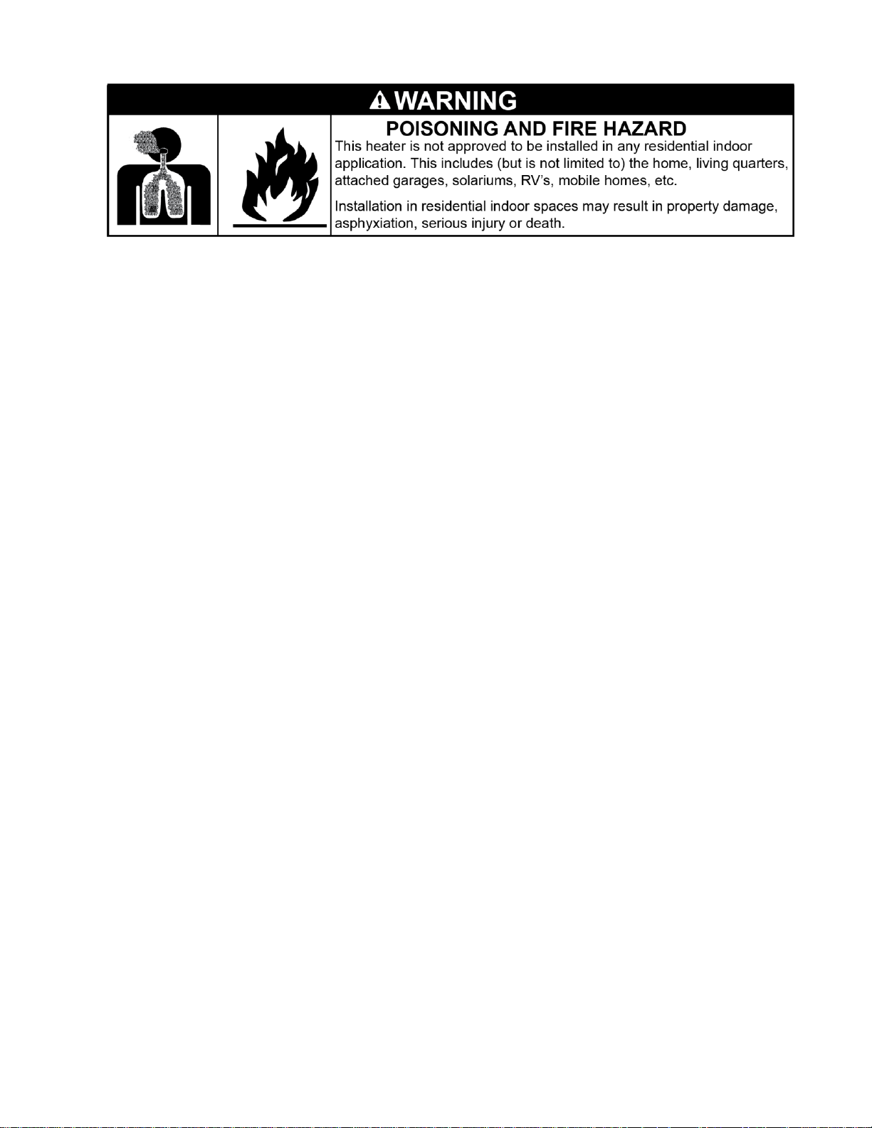
This heater is a self-contained infrared radiant ceramic patio heater for use in locations where flammable gases or
vapors are not generally present and is intended for space heating non-residential spaces.
This patio heater model is approved to two different heater standards:
A “Patio Heater” for Outdoor Use in Residential and Commercial/Industrial Applications.
And as a “Gas-Fired High Intensity Infrared Heater” for Indoor Spaces of Commercial/ Industrial Applications.
Not for use in residential dwellings.
Note: A residential dwelling is a domicile intended for use by one or more persons and that
includes one or more areas, such as those used for cooking, eating, living, sleeping, or a sanitary
facility. A residential dwelling does not include a workshop, or outdoors.
Form 44201440 2
Mar 2019
Page 4
SAFETY REQUIREMENTS
The heater area must be kept clear and free from combustible materials, gasoline and other flammable vapors
and liquids.
This heater is designed for use with one type of gas (LPG or Natural). Make sure that the type of gas to be
supplied to this heater matches that shown on the heater rating plate.
DO NOT install this heater directly onto an LPG container or propane cylinder. LPG containers (propane cylinders)
must not be stored indoors or in the vicinity of any gas-burning appliance.
DO NOT Store flammable materials near the heater.
DO NOT locate gas and electric supply lines directly above the heaters path of flue products. The pa th of flue
products will change if an optional low clearance heat shield is installed.
Children and adults should be alerted to the hazards of high surface temperatures and should stay away to avoid
burns or clothing ignition.
Young Children should be carefully supervised when they are in the area of the heater.
DO NOT spray aerosols or flammable materials in the vicinity of this appliance while it is in operation.
Clothing or other flammable materials should not be hung from the heater or placed on or near the heater.
NEVER attempt to service the heater while it is plugged in, operating or hot.
Any guard or other protective device removed for servicing a heater must be replaced prior to operating the
heater.
DO NOT Install the heater in a recess, alcove or enclosure.
Installation and repair should be done by a licensed contractor qualified in the installation and service of gas
heating equipment. The heater should be inspected before use and at least annually by a qualified service person.
More frequent cleaning may be required as necessary. It is imperative that the control compartment, air
passageways and burner of the heater be kept clean.
If any changes are made to the patio or building structure after the heaters are installed such as adding plastic
curtains to enclose the patio the modified design must be checked by a qualified person to ensure that the
clearance combustibles and ventilation requirements are maintained.
DO NOT paint any surface of the heater.
DO NOT throw objects at the heater.
Avoid inhaling fumes emitted from the heater’s first use. Smoke and odor from the burning of oils used in
manufacturing will appear. Both the smoke and odor will dissipate after approximately 30 minutes.
INSTALLATION REQUIREMENTS
Installation of this heater must conform with local building codes or, in the absence of local codes, with the National
Fuel Gas Code, ANSI Z223.1/NFPA 54, or the Natural Gas and Propane Installation Code, CSA B149.1 In Canada, the
installation must conform to current CSA B149.1 (The Natural Gas and Propane Installation Code) in the absence of
local codes. Heaters shall be installed by a licensed contractor or licensed installer. Clearances to combustibles as
outlined in this manual should always be observed. In areas used for storage of combustible materials where they
may be stacked below the heater, NFPA54 requires that the installer must post signs that will “specify the maximum
permissible stacking height to maintain the required clearances from the heater to combustibles.”
Every heater shall be located with respect to building construction and other equipment so as to permit access to the
heater. Each installer shall use quality installation practices when locating the heater and must give consideration to
clearances to combustible materials, vehicles parked below, lights, overhead doors, storage areas with stacked
materials, sprinkler heads, gas and electrical lines, and any other possible obstructions or hazards. Consideration
also must be given to service accessibility.
Form 44201440 3
Mar 2019
Page 5
Sunstar will not recognize the warranty for any use other than space heating.
(FOR CANADA ONLY)
a. Installation of this appliance is to be in accordance with latest edition of CSA B149.1 (Natural Gas and Propane
Installation Code).
b. For installation in public garages or aircraft hangars, the minimum clearances from the bottom of the infrared
heater to the upper surface of the highest aircraft or vehicle shall be 50 percent greater than the certified
minimum clearance, but the clearance shall not be less than 8 feet.
This heater is for Indoor and Outdoor Installation and is used in Unvented mode. The term Unvented actually means
Indirect Vented. While the products of combustion are expelled into the building, national codes require 4 CFM/1000
BTU of heater input ventilation in the building to dilute these products of combustion. This ventilation may be
provided by gravity or mechanical means.
This heater is not an explosion proof heater. Where the possibility of exposure to volatile and low flash point
materials exists, it could result in property damage or death. This heater must not be installed in a spray booth where
the heater can operate during the spraying process. Consult your local fire marshal or insurance company.
This heater must be applied and operated under the general concepts of reasonable use and installed using best
building practices.
It is the responsibility of the qualified installer to supply the appropriate lifting equip ment to safely install the radiant
heater. Tools required for the safe installation, startup and maintenance are various screwdrivers, wrenches, pipe
wrenches, voltmeter, air and gas manometer, level and required tools to safely install the chosen hanging materials.
Do not install this heater indoors in a structure with no insulation in the roof—condensation will
occur.
The heater, when installed in aircraft hangars and public garages, must be installed in accordance with ANSI/NFPA
409-latest edition (Standard for Aircraft Hangars), ANSI/NFPA 88a-latest edition (Standard for Parking Structures),
and ANSI/NFPA 88b-latest edition (Standard for Repair Garages) with the following clearances:
a. At least 10 feet above the upper surfaces of wings or engine enclosures of the highest aircraft that may be
housed in the hangar and at least 8 feet above the floor in shops, offices, and other sections of hangars
communicating with aircraft storage or service areas.
b. At least 8 feet above the floor in public garages. ▲WARNING: Minimum clearances marked on the heater must
be maintained from vehicles parked below the heater.
MINIMUM CLEARANCES TO COMBUSTIBLES 4.0)
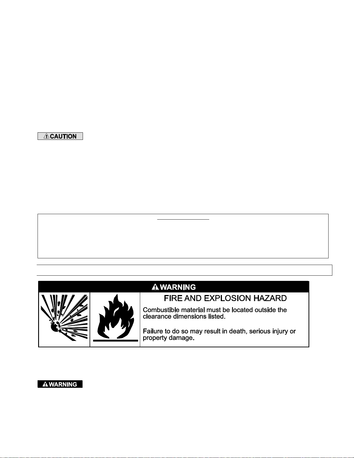
A critical safety factor to consider before installation is the clearances to combustible materials. Clearance to
combustibles is defined as the minimum distance you must have between the surfaces of the heater and the
combustible item. Considerations must also be made for moving objects around the infrared heater.
This heater must not be installed where the products of combustion can build up and prevent them
being exhausted to the atmosphere. This includes applications such as; enclosures, recessed ceilings and alcoves.
Form 44201440 4
Mar 2019
Page 6
This heater can be equipped with a heat shield to reduce the clearances to combustibles towards
the ceiling. Due to the variety of possible heater mounting angles the heat shield must be mounted in the correct
location to match the heater mounting angle. See section 13.0 heat shield installation.
Approved installation angles are 0, 15, 30, 45 and 60 degrees with the heat shield installed.
Certain materials or objects, when stored under the heater, will be subjected to radiant heat and
could be seriously damaged. Observe the Minimum Clearances to Combustibles listed in the manual and on the
heater at all times.
For maximum safety the building must be evaluated for hazards before installing the heater system.
Examples include, but are not limited to:
Gas and electrical lines
Combustible and explosive materials
Chemical storage areas
Areas of high chemical fume concentrations
Provisions for accessibility to the heater
Adequate clearances around the openings
Combustion and ventilating air supply
Vehicles parking areas
Vehicles with lifts or cranes
Storage areas with stacked materials
Lights
Sprinkler heads
Overhead doors and tracks
Dirty, contaminated environment
This heater is approved for both INDOOR and OUTDOOR installation. Both installation options have different clearances
to combustibles as described below. These must be observed.
INDOOR clearances to combustibles are defined as a surface temperature of 90°F above ambient temperature.
OUTDOOR clearances to combustibles are defined as a surface temperature of 117°F above ambient temperature.
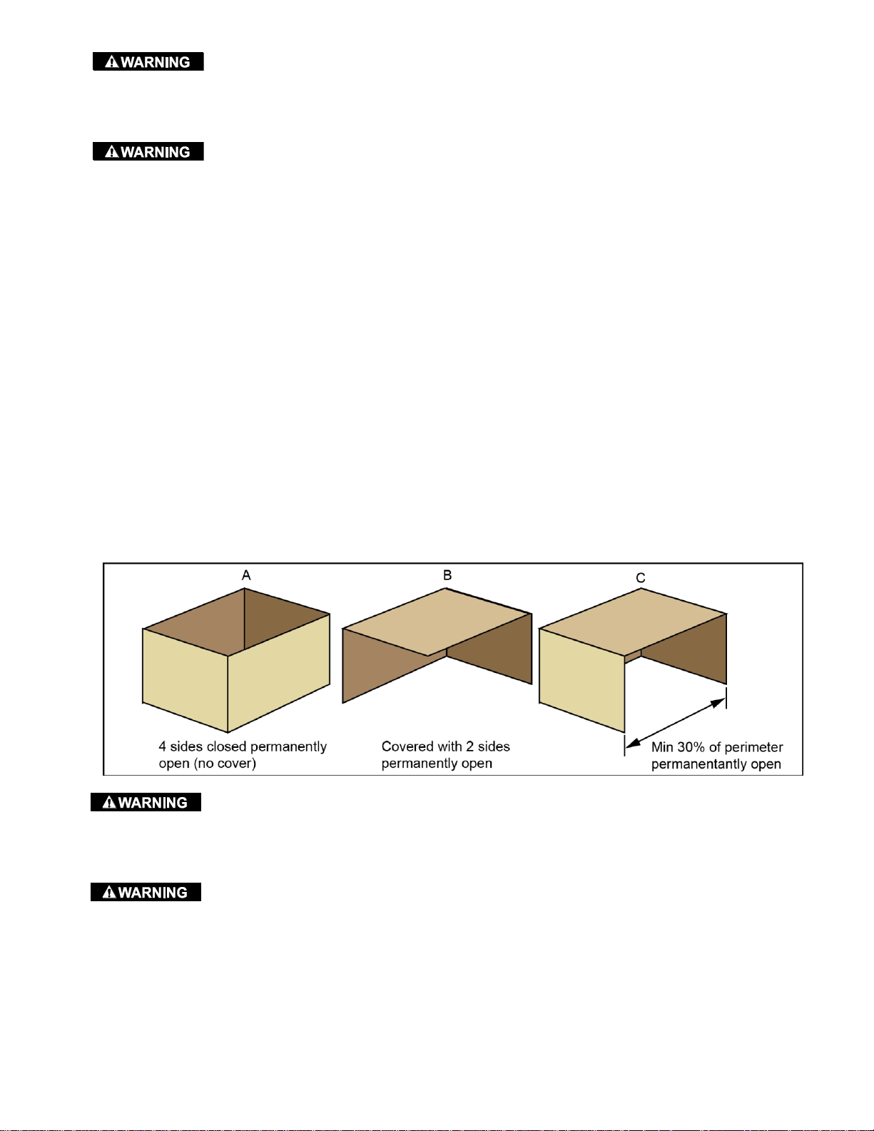
OUTDOOR Spaces are defined as a shelter no more inclusive than:
a) with walls on all sides, but with no overhead cover.
b) within a partial enclosure which includes an overhead cover and no more than two side walls. These side
walls may be parallel, as in a breezeway, or at right angles to each other.
c) Within a partial enclosure which includes an overhead cover and three side walls, as long as 30 percent or
more of the horizontal periphery of the enclosure is permanently open.
For the purposes of clearances to combustibles and ventilation all applications not classified as
outdoors according to the definitions above shall comply with the requirements for indoor installations.
Minimum clearances shall be measured from the outer surfaces of the heater or heat shield if installed, as shown in
the diagrams for the different installation positions.
Fire sprinkler heads must be located at an appropriate distance from the heater. This distance
may exceed the published clearance to combustibles. The exhaust gas temperature will be 800°F (426°C) and above
where it exits the heater. Certain applications will require the use of high temperature sprinkler heads or relocation of
the heaters. Sprinkler head temperatures lower than “blue color code” might not be suitable in the vicinity of the
heater.
Sprinkler systems containing propylene glycol or other flammable substances are not to be used in conjunction with
this heater without careful consideration for and avoidance of potential fire or explosion hazards. For further
information consult the authority having jurisdiction. Always observe applicable state and local codes.
Form 44201440 5
Mar 2019
Page 7
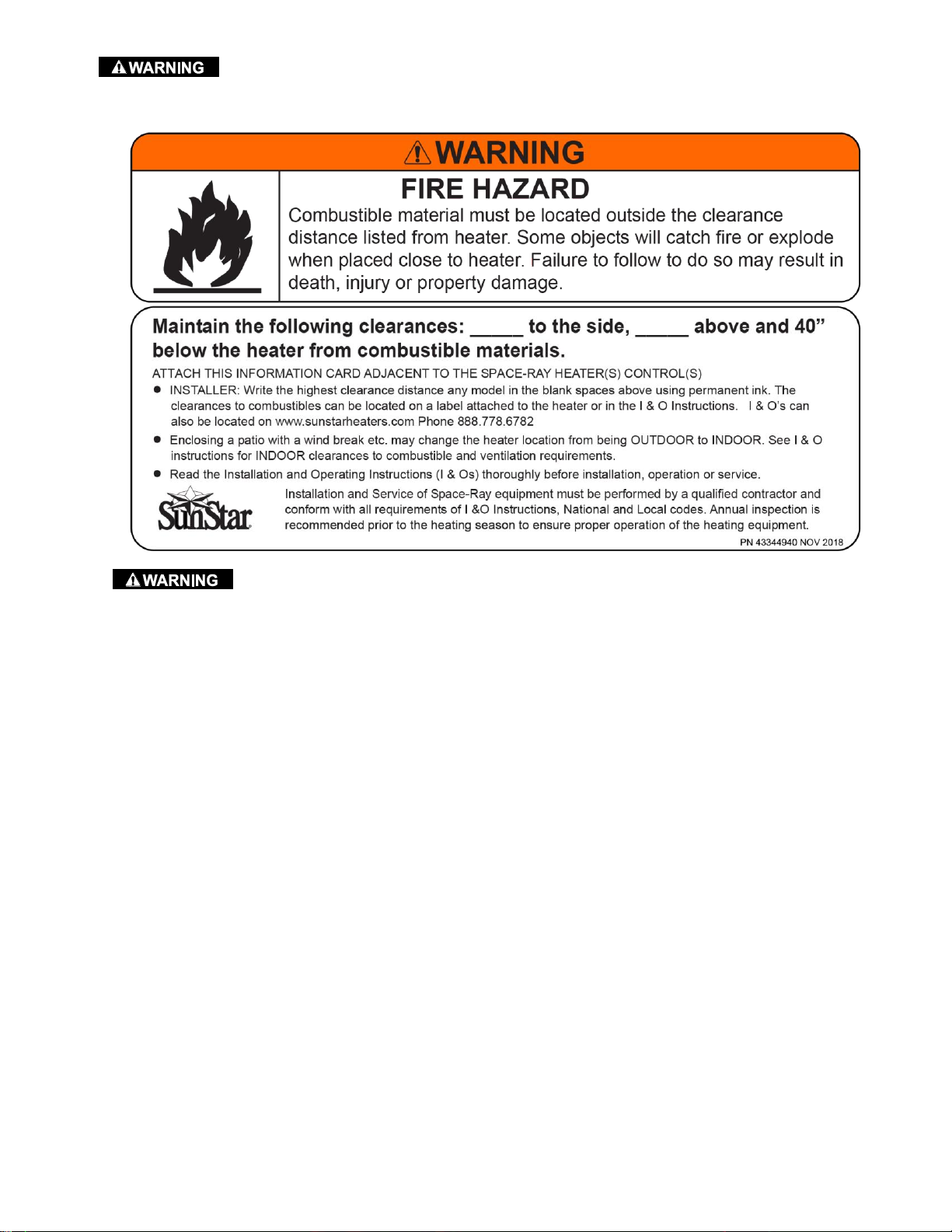
Always maintain minimum clearances and post signs where needed. This heater is supplied with a
wall mounted sign shown below. It is the installers responsibility to ensure that the sign is completed with the correct
clearance to combustible distances for the installation and that the sign is posted in a location where it is easily
accessed.
Clearances to combustibles are posted on the heater. In areas used for storage of combustible
materials where they may be stacked below the heater the installer must post signs that will “specify the maximum
permissible stacking height to maintain the required clearances from the heater to combustibles.” Sunstar
recommends posting these signs adjacent to the heater thermostat or other suitable location that will provide
enhanced visibility.
Form 44201440 7
Mar 2019
Page 8
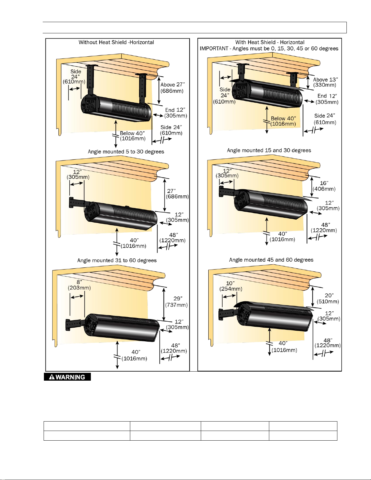
INDOOR CLEARANCES TO COMBUSTIBLES 4.1)
Ambient Temperature
70°F (21.1°C)
65°F (18.3°C)
60°F (15.5°C)
Surface Temperature
160°F (71.1°C)
155°F (68.3°C)
150°F (65.6°C)
room temperature. Building materials with a low heat tolerance (such as plastics, vinyl siding, canvas, tri -ply, etc.)
may be subject to degradation at lower temperatures. It is the installer’s responsibility to assure that adjacent
materials are protected from degradation.
See below the possible surface temperature at the clearance to combustible distance for different ambient
temperatures within the heated space.
Form 44201440 8
Mar 2019
The stated clearance to combustibles represents a surface temperature of 90º F (50º C) above
Page 9
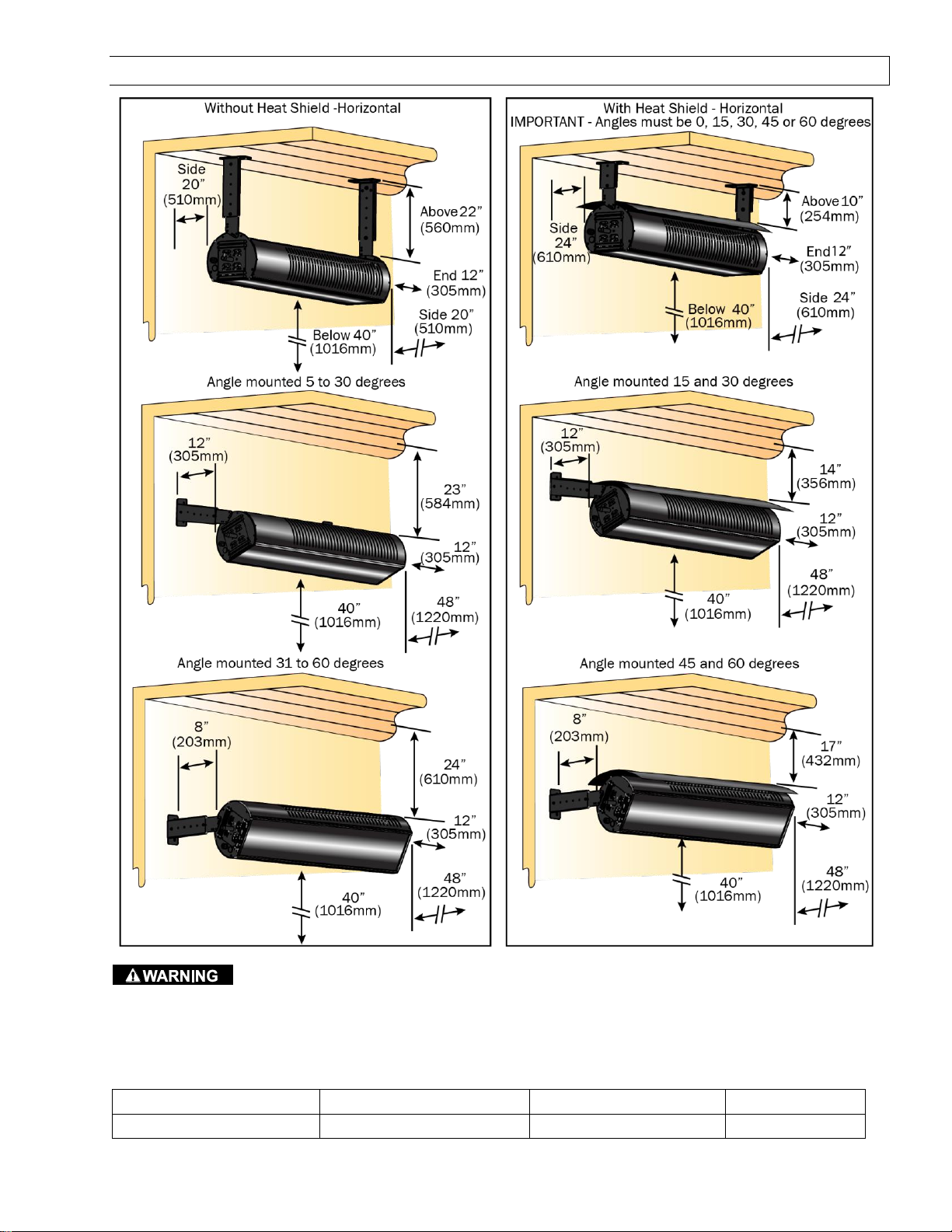
OUTDOOR CLEARANCES TO COMBUSTIBLES 4.2)
Ambient Temperature
70°F (21.1°C)
65°F (18.3°C)
60°F (15.5°C)
Surface Temperature
187°F (86.1°C)
182°F (83.3°C)
177°F (80.6°C)
room temperature. Building materials with a low heat tolerance (such as plastics, vinyl siding, canvas, tri -ply, etc.)
may be subject to degradation at lower temperatures. It is the installer’s responsibility to assure that adjacent
materials are protected from degradation.
See below the possible surface temperature at the clearance to combustible distance for different ambient
temperatures within the heated space.
Form 44201440 9
Mar 2019
The stated clearance to combustibles represents a surface temperature of 117º F (65º C) above
Page 10
SPECIFICATIONS 5.0)
Model No.
Btu/hr
High
Input
(2-stage)
Btu/hr
Low
Input
Orifice Size
Recommended*
Mounting Height
Natural Gas
Propane Gas
@ 0 º
@ 5 º
to 30 º
@ 30º
to 60 º
SGL35-N7
35,000
24,000
#41
0.096
inch
#51
0.067
inch
8 to 11 ft
7 to 9 ft
6.5 to 8 ft
SGL35-L7
35,000
24,000
Control Option Suffix
Gas Type
Description
N7
Natural
Two Stage White-Rodgers 36J Gas Valve – High/Low Fire
L7
Propane
Two Stage White-Rodgers 36J Gas Valve – High/Low Fire
Type
Gas
Gas Pipe
Connection
Electrical
Supply
Current
Rating
Weight
Natural
or Propane
½” NPT
(Male)
120 Volt, 60Hz,
1 Phase
0.1 Amp
55 lbs
Module Electrical Rating:
Ignition System (direct spark):
Input-Control: 18-30 VAC 50/60 Hz (class 2 transformer)
Input Power-Line: 120 VAC (L1, IND contacts only)
Flame Sensitivity: 0.7 µA (microamps) minimum
10 second trial for ignition period
7 second pre-purge period
15 second inter-purge period
3 tries for ignition
separate flame sensor
potted, 100% water protected
Model
Part Number
Gas Type
SGL35-N7
44575220
Natural
SGL35-L7
44575230
Propane
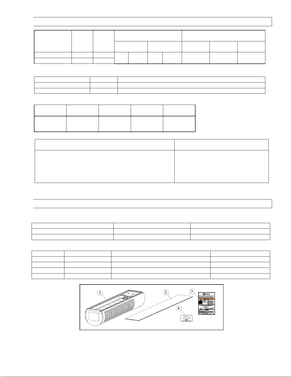
Number
Part Number
Description
Qty Per
1
See Above
Patio Heater
1
2
41373050
Ceramic Glass 4mm Black
1 3 43344990
Sunstar Clearances sign
1
4
44568039
Angle Mounting Gauge Plate
1
* For mounting heights outside the recommended distances consult your local Sunstar Representative.
Model Identification:
Two stage heaters are supplied with a jumper to enable single stage (high fire only) operation. See electrical section
16.0 for instructions.
Approved installation angles are 0, 15, 30, 45 and 60 degrees with heat shield installed.
PACKING LIST 6.0)
Package contents are listed below:
Form 44201440 10
Mar 2019
Page 11
HEATER SIZING GUIDELINES 7.0)
Mounting Angle
15 degree
30 degree
45 degree
60 degree
Radiant output reduction
3%
13%
29%
50%
Mounting Angle
Mounting Height
Breezy Exposed
Location
Moderately
Protected
Well
Protected
Horizontal
8ft. – 11ft.
(2.4 – 3.4m)
8 x 8 ft
(2.4 x 2.4m)
10 x 10 ft.
(3.0 x 3.0m)
12 x 12 ft.
(3.7 x 3.7m)
Up to 30 Degrees Angled
7ft. – 9ft.
(2.1 – 2.7m)
8 x 8 ft
(2.4 x 2.4m)
9 x 9 ft.
(2.7 x 2.7m)
11 x 11 ft.
(3.4 x 3.4m)
30 to 60 Degrees Angled
6.5ft. – 8ft.
(1.9 – 2.4m)
Not Recommended
8 x 8 ft.
(2.4 x 2.4m)
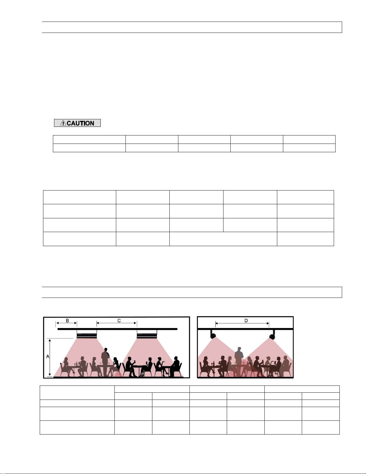
Dimension
Horizontal
15 to 30 degree angle
Above 30 degree angle
Min.
Max.
Min.
Max.
Min.
Max.
A. Mounting Height
8ft (2.4m)
11ft (3.4m)
7ft (2.1m)
9ft (2.7m)
6ft (1.8m)
8ft (2.4m)
B. Distance to the end of
the patio
0ft (0m)
6ft (1.8m)
0ft (0m)
6ft (1.8m)
0ft (0m)
6ft (1.8m)
C. Distance between
heaters.
8ft (2.4m)
12ft (3.7m)
7ft (2.1m)
11ft (3.4m)
6ft (1.8m)
10ft (3.0m)
Radiant heaters work like the sun to emit radiant heat directly to the space to increase the comfort of the patio
guests. Suitable applications include patios, porches, outdoor shopping areas and pathways.
The amount of temperature increase in outdoor patio spaces will be dependent on the following factors:
1. The number of heaters in the space is important to provide good coverage of the area to be heated.
2. Take care not to mount the heaters too low or too close together this can make people directly below the
heaters uncomfortable.
3. It is recommended to use a suitable windbreak to reduce the effects of direct wind on the patio. If an area is
going to be unprotected and is a breezy location then heaters may need to located closer together. Wind
breaks must be designed to allow fresh air for ventilation.
4. Angling the heaters greater than 30 degrees should be avoided unless the mounting height is low, when the
heaters are angled more than 30 degrees the radiant intensity is lower and will reduce the amount of heat felt
by the guests.
When angle mounting the heater the radiant output will decrease approximately by
following:
5. It is recommended to place the heaters in the area of greatest heat loss facing into the patio area.
The table below shows minimum area coverage per heater for outdoor patio heating based on a 5 to 10°F (2. 8 to
5.6°C) temperature rise.
Note: When sizing the number of heaters to warm the patio, the area coverage given above may not provide the
stated temperature rise under all weather conditions and will be dependent on heater placement. Minimums are
shown as a guideline for human comfort. For more assistance with patio heater sizing and layout please contact
your local Sunstar representative.
TYPICAL HEATER LAYOUTS 8.0)
The diagram below shows the recommended spacing layout between heaters.
Form 44201440 11
Mar 2019
Page 12

D. Distance between
heaters*
8ft (2.4m)
16ft (4.9m)
8ft (2.4m)
18ft (5.5m)
8ft (2.4m)
16ft (4.9m)
*Note the distance D for angled heaters applies when they are facing towards each other.
Note: Local codes may have special requirements regarding head clearance requirements. Some local codes
require all portions of overhead radiant heaters to be located at least 8 feet above the floor.
Below are examples of patio heating applications.
Form 44201440 12
Mar 2019
Page 13
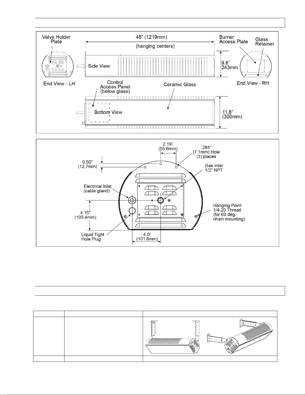
DIMENSIONS 9.0)
PN
Description
PIcture
44560350
Wall / Ceiling Telescopic
Mounting Bracket Kit- 15"-22"
overhead space (check
clearances to combustibles space
above the heater before ordering)
44560351
Ceiling Telescopic Mounting
ACCESSORIES 10.0)
Below are the optional accessories available for the SunStar Glass Patio heater.
Form 44201440 13
Mar 2019
Page 14
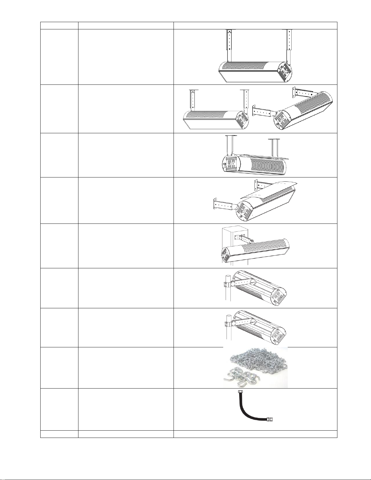
PN
Description
PIcture
Bracket Kit- 22"-30" overhead
space (check clearances to
combustibles space above the
heater before ordering)
44560352
Wall / Ceiling Telescopic
Mounting Bracket Kit- 15"-30"
overhead space (check
clearances to combustibles space
above the heater before ordering)
includes both the 15-22” and 2230” extension legs.
44560353
Ceiling Mount Bracket Kit- 10"
fixed installation for minimum
overhead clearance. This bracket
is only for horizontal mounting
with the heat shield
44566300
Heat Shield Kit – Reduced
clearances to combustible option
when installed. Mounting angles
are restricted to 0, 15, 30, 45 and
60°.
44560590
Column Mounting Arm Kit –
suitable for columns 8” and wider.
44560600
3 " Pole Mounting Bracket Kit
44560609
4" Pole Mounting Bracket Kit
41690120
Chain Kit, 12 ft. chain w/ 8 hooks
30302241
Gas Connector - Black Powder
Coated Paint to match the heater.
1/2"OD -24" Long with 1/2MIP X
1/2 FIP Connection
44604500
Gas Connection Kit- 1/2"-Includes
Form 44201440 14
Mar 2019
Page 15

PN
Description
PIcture
Gas Connector, Manual Ball Valve,
Sediment Trap (Tee, Cap, Nipple),
Thread Sealing Compound
03307260
Gas regulator 2psig to 11” w.c. ½”
NPT inlet and outlet.
40147010
3 Position Switch Kit,
(High/Low/Off) for manual heater
control (N7/L7)
44195000
Two Stage Relay Kit (one per
heater required) for controlling
multiple heaters w/a single 24V
Two Stage thermostat
UNPACKING THE HEATER 11.0)
The heater and ceramic glass are shipped separate but in the same box. Care must be taken
when up-packing the heater. Carefully open the top of the heater as indicated on the labels at the side of the
shipping box. An angle gauge is attached to the heater’s control side with tape and is needed for installation (see
Section 12.1).
The glass is located on top of the heater and is wrapped in cardboard cradled into the foam end pieces. Carefully
remove the top foam pieces and remove the cardboard wrapped glass. Care must be taken that during handling
the glass does not slide out of the cardboard wrap. Store the glass in a secure location for later assembly.
remaining packaging until the heater is ready to be hung.
Form 44201440 15
Mar 2019
It is recommended that two people lift the heater out of the carton. Do not remove from the
Page 16

INSTALLATION 12.0)
In order to protect the ceramic glass it is recommended to only insert the ceramic glass once all the other
installation steps have been completed. The ceramic glass must be removed to wire the heater and for
commissioning.
Various means of suspending the heater can be used. See the following drawings for typical examples.
a) Heaters installed outdoors or in areas subject to strong winds must be installed using the optional hanging
brackets or suitable rigid mount hardware. Chain, cable and other flexible hanging methods are not
recommended.
b) Use only noncombustible materials for suspending hangers and brackets.
c) Turnbuckles can be used with chains to allow leveling of the heater. All “S” hooks and eye bolts must be
manually crimped closed by the installer.
d) Heaters must not be supported by gas or electric supply lines and must be suspended from a permanent
structure with adequate load capacity.
e) Hanging points are a fixed length between centers. Secondary steel work may be required to span between
supporting beams.
f) The appliance should be located with respect to building construction and other equipment to permit
access to the appliance for servicing etc.
f) The heater must be installed in an adequate free area to allow the products of combustion to freely escape
from the heater. The heater must not be installed in recessed spaces or enclosure and alcoves.
g) The heater must be suspended with its longitudinal axis horizontal, but may have its lateral axis at an angle
from 00 to 600 from the horizontal, as shown in the minimum clearances to combustibles section 4.0).
h) An optional heat shield may be installed to reduce the top distance of clearance to combustibles. This heat
shield should be installed prior to hanging the heater. When using the heat shield at the minimum
clearance distance the angles of installation are restricted to 0, 15, 30, 45 and 60°.
i) Use the provided angle gauge to ensure that the heater is hung at the approved installation angles.
j) The heater can be angle mounted on both sides of its lateral axis.
k) Hanging brackets should first be fixed to the wall surface by means of 4 lag bolts – not supplied (3/8” x 1-
1/2” minimum) through pre-formed holes in each of the brackets prior to installing heater.
Form 44201440 16
Mar 2019
Page 17

HEATER MOUNTING ANGLE 12.1)
Every heater is supplied with an angle gauge. The gauge is attached with tape to the heater control side.
The angle gauge is used in combination with a level to ensure that the heater is installed at one of the mounting
angles of 00, 150, 300, 450 and 600.
Hold the side of the angle gauge without label flush against the glass surface. Hold a level against the other side of
the angle gauge and find the desired installation angle of the heater. Verify that the level is vertical, adjust heater
angle if needed.
Note: If a heat shield is installed its location must match the heaters angle (see Section 21.0).
This process must be repeated for both ends of the heater.
INDOOR INSTALLATION – HANGING METHODS 12.2)
When the heater is used for an Indoor Installation then the following hanging methods may be used.
The heater can be hung from the ceiling, secondary steel work, etc. using chains, threaded rods and other approved
hanging materials. All hanging materials must have a minimum working load of 115 lbs. Any “S” hooks must be
crimped closed after installation.
Note:
Form 44201440 17
Mar 2019
Page 18

When hanging the heater hanging materials which allow the heater to move the gas connection must be
Item No.
Part No.
Description
44560350
Quantity
44560351
Quantity
44560353
Quantity
1
02140040
HHCS,1/4-20 x 1/2" SS
6 6 6
2
02129100
WASHER, FLAT 1/4"N SS
6 6 6
3
02167019
LOCKNUT, 1/4-20 KEPS - SS
6 6 6
4
44560250
HANGER BRACKET – RECEIVER
2 2
5
44560260
SLIDER ARM – LH
1
6
44560270
SLIDER ARM – RH
1
7
44560289
SLIDER ARM – LH
1
8
44560299
SLIDER ARM – RH
1
9
44560809
FIXED ARM
2
established using an approved flexible gas hose of a minimum of 24” length.
Diagram below shows Horizontal mounting with chain.
Diagram below shows the possible chain methods to hang at different angles.
Notes: When suspending at 25 degrees if the heat shield is installed use the 30-degree location for the heat shield.
INDOOR / OUTDOOR RIGID HANGING BRACKETS 12.3)
Fixed hanging methods which prevent the heater from swaying must be used for outdoor installations.
Below are the bracket kits which can be used for ceiling and wall mount for patio heaters installed indoors and
outdoors, with and without heat shields. The brackets provide for a range of lengths and approved mounting angles
of 150, 300, 450 and 600.
44560350 KIT, BRACKET - WALL/CEILING 15"-22" CEILING - FOR USE WITH HEAT SHIELD (telescoping)
44560351 KIT, BRACKET - CEILING 22"-30" - FOR USE WITHOUT HEAT SHIELD (telescoping)
44560353 KIT, BRACKET - CEILING 10" – FIXED (for outdoor only horizontal ceiling mount with heat shield)
The hanging brackets are supplied as an optional accessory item. Below are the kit contents.
Form 44201440 18
Mar 2019
Page 19

15-22” Bracket (With heat shield)
telescope hole positions*
22-30” Bracket (Without heat shield)
telescope hole positions*
Mounting Angle
INDOOR
OUTDOOR
INDOOR
OUTDOOR
0
1 to 5
1 to 5
3 to 5
1 to 5
15 and 30
2 to 5
1 to 5
3 to 5
1 to 5
45 and 60
4 or 5
2 to 5
4 or 5
2 to 5
12.3.1) HANGING BRACKETS ASSEMBLY
The tables below can be used to select the correct bracket to ensure that the heater is installed at the correct
clearance to combustible distance from the ceiling depending on whether the heater is installed indoors or
outdoors, the mounting angle and whether a heat shield is installed.
* The above table relates to the holes positions as shown in the figure below for the two different length adjustable
brackets.
Form 44201440 19
Mar 2019
Page 20

A left-hand LH and right-hand RH bracket must be assembled. Torque screws and locknuts to 5 lbf⋅ft.
12.3.2) HEATER ATTACHMENT TO HANGING BRACKETS
Mounting Angle
15 degree
30 degree
45 degree
60 degree
Radiant output reduction
3%
13%
29%
50%
To mount the hanging brackets to the wall/ceiling:
1. Measure and mark distances for the hanger bracket holes.
2. Hanging brackets should first be fixed to the wall or ceiling surface by means of 4 lag bolts – (not supplied)
(3/8” x 1-1/2” minimum) through pre-formed holes in each of the brackets prior to installing heater. All
hanging materials must have a minimum working load of 115lbs
The heater can be attached to the hanging brackets in angles of 150, 300, 450 and 600. Choose the desired heater
mounting angle and find the corresponding hole pattern as per the wall and ceiling mount figures below.
When angle mounting the heater the radiant output will decrease approximately by
following:
Attach the heater to the brackets using (2) cap screws, flat washers and locknuts provided in the kit. Torque screws
and locknuts to 5 lbf⋅ft. Minimum clearances to combustible must be observed. See Section 4).
Form 44201440 20
Mar 2019
Page 21

HEAT SHIELD INSTALLATION 13.0)
Item No.
Part No.
Description
Quantity
1
02359000
#10-24 ACORN NUT
2
2
02358000
TEFLON WASHER
4
3
02186010
#10-24 SS LOCKNUT NUT
2
4
02352000
PHSMS #8 x 1/2" AB POINT SS - BLK OXIDE
8
5
44568139
RAIL - HEAT SHIELD HANGER - PAINTED
1
6
44566189
HEAT SHIELD - ROLLED/PAINTED
1
7
44568149
HOLDER BRACKET - PAINTED
2
8
43247112
LABEL, INDOOR CLEARANCES (with heat shield)
1
A heat shield can be used to reduce the clearance to combustible distances. Refer to Minimum Clearance to
Combustibles in Section 4). The heat shield is available as an accessory Kit No. 44566300.
The heat shield position on the heater is dependent on the heater mounting angle. Use the angle gauge provided
with the heater to determine the mounting angle before proceeding with the heat shield assembly. See Section
12.1
See below for installation steps.
Step 1. Use the angle gauge shown below to determine the mounting angle of the heater.
Form 44201440 21
Mar 2019
Page 22

Step 2. Attach the (2) holder brackets to the top of the heater using (2) black oxide #8 screws per bracket.
Step 3. Identify the correct holes to mount the shield hanger rail from the illustration below.
Step 4. Attach the heat shield hanger rail to the holder bracket using (2) black oxide #8 screws on each end.
Horizontal position shown below.
IMPORTANT: Use the Acorn nuts at the control end of the heater as shown in the illustrations so
that the heat shield can expand when the heater is turned on. Failure to do so may result in the heat shield
distorting.
Step 5. Attach the heat shield to the hanger rail using the holes in the heat shield indicated below for horizontal
mounting.
Form 44201440 22
Mar 2019
Page 23

Step 6. Place the new clearance label on the control end of the heater. NO NOT PLACE LABEL ON THE HEAT SHIELD.
See below the correct holes to mount the heat shield to the hanger rail for other installation angles.
ASSEMBLY OF THE CERAMIC GLASS 14.0)
Only install the ceramic glass once the heater has been attached to a suitable gas (see Section 15.0), electrical
supply (see Section 16.0) and has been commissioned (see Section 18.0).
Read this section to the end to avoid glass breakage.
1. Locate the “Glass Access Retainer” and carefully remove with a suitable Phillips screw driver the two (2)
black oxide sheet metal screws holding it in place. Retain screws and Glass Access Retainer for later.
Form 44201440 23
Mar 2019
Page 24

2. The side of the glass where the logo is attached must be slid in first for the logo’s final position to be at the
control side of the heater.
3. Slide the glass into the “Glass Retainer Rails”. The glass must be held parallel to the Glass Retainer Rails
during assembly. The glass will slide in easy with ample clearance. Slide the glass until it is positioned
under the Glass Retainer at the heaters control enclosure side. At this point the glass will be flush with the
heater at the insertion point.
Note: If the ceramic glass does not slide in easily review position of ceramic glass to glass retainers and
adjust if needed. Do not force the ceramic glass into the glass retainers!
4. Reinstall the Glass Access Retainer removed in 1. with the two (2) sheet metal screws.
15.0)
GAS CONNECTIONS AND REGULATION
Use an approved flexible gas connector of 24” minimum length when installing the heater with
flexible hanging methods as described in Section 12.0).
Form 44201440 24
Mar 2019
Page 25

IMPORTANT BEFORE CONNECTING THE GAS TO THE HEATER
GAS PRESSURE TABLE
GAS TYPE
MANIFOLD PRESSURE
SUPPLY PRESSURE
High
Low (2-stage only)
Minimum*
Maximum
Natural Gas N7
6.0” W.C.
2.8” W.C.
7” W.C.
14” W.C.
Propane Gas L7
11.0” W.C.
5.0” W.C.
11.5” W.C.
14” W.C.
a) Connect to the supply tank or manifold in accordance with state or local building codes. Authorities having
jurisdiction should be consulted before the installation is made. (In Canada, refer to the latest edition of
CSA B149.1, Natural Gas and Propane Installation Code.)
b) Check that the gas fuel on the burner rating plate matches the fuel for the application.
c) Check that the gas supply piping has the capacity for the total gas consumption of the heaters and any
other equipment connected to the line.
d) Check that the calculated supply pressure with all gas appliances and heaters operating will not drop
below the minimum supply pressure required for these heaters. See table below.
e) All gas supply lines must be located in accordance with the required clearances to combustibles from the
heater as listed on the clearances label of the heater and Section 4.0) of this manual.
f) Pipe joint compounds must be resistant to the action of liquefied petroleum gases.
g) The heater will move when installed with flexible hanging methods, see Section 12.0). Use an approved
flexible connector for connections between the rigid piping and the heater. An approved shut off valve
should be installed within 6ft of the heater.
h) The gas pipe, flexible hose and connections must be self-supporting. The gas pipe work must not bear any
of the weight of the heater or any other suspended assembly.
i) This appliance is equipped with a fast-opening, combination gas valve. The maximum supply pressure to
the appliance is 14” W.C. (1/2 psig) If the line pressure is more than the maximum supply pressure, then a
second stage regulator which corresponds to the supply pressure must be used
j) After all gas connections have been made, make sure the heater and all gas outlets are turned off before
the main gas supply is turned on slowly. Turn the gas supply pressure on and check for leaks.
k) If a 2nd stage regulator is used, the ball valve before the heater in the supply line must be closed when
purging the gas lines to prevent gas seeping through it. If initial gas pressure is higher than 14” W.C. the
redundant combination gas valve is designed to lock out. Pressure build-up in the supply lines prior to the
heater must be released before proper heater operation.
l) High gas pressure regulators need to be installed upstream of flexible gas lines.
The entire gas supply system must be checked for leaks prior to heater operation. Do not use an
open flame of any kind to test for leaks.
Flexible Hose Connections
Form 44201440 25
Mar 2019
Page 26

INSTRUCTIONS FOR PRESSURE TEST GAUGE CONNECTION 15.1)
INLET GAS PRESSURE CHECK 15.2)
1. The installer will provide a 1/8” N.P.T. tapped plug, accessible for test gauge connection immediately upstream
of the gas supply connection to the heater.
Form 44201440 26
Mar 2019
Page 27

OUTLET GAS PRESSURE CHECK AND ADJUSTMENTS
15.3)
Gauges that measure pressure in pounds per square inch are not accurate enough to measure or set the manifold
pressure. All measurements MUST BE made when the heater and all other gas burning equipment that are
connectied to the gas supply system are operating at maximum capacity. The combination gas valve is factory set
and should not need adjustment. If gas pressure adjustment is required, follow the instructions:
1. Turn off all electrical power to the system to connect manometer hoses.
2. Turn the pressure test screw (3/32” Hex) in the center of the boss not more than one turn counterclockwise.
Attach a 5/16” hose and manometer over the tapered outlet pressure boss on the valve (see Figure 1 below).
If regulator needs to be adjusted, see instructions below.
TO ADJUST REGULATOR (two stage gas valves):
1. Turn on power and energize main gas valve solenoid. Do not energize the HI solenoid.
2. Remove regulator cover screw from the low outlet pressure regulator (see Figure 1 below) and turn screw
clockwise to increase pressure, or counterclockwise to decrease pressure. Replace regulator cover
screw and tighten securely.
3. Energize main gas valve solenoid as well as the HI terminal.
4. Remove regulator cover screw from the high outlet pressure regulator (see Figure 1 below) and turn screw
clockwise to increase pressure, or counterclockwise to decrease pressure. Replace regulator cover
screw and tighten securely.
DO NOT EXCEED THE PRESSURES SHOWN IN THE GAS PRESSURE TABLE.
5. After testing pressure and adjusting the regulator, turn off all electrical power to the system, remove
manometer hoses, turn outlet test screw (3/32” Hex) clockwise to seal pressure port. Tighten to 7 in-lb
minimum. Turn on system power.
GAS PRESSURE TABLE
GAS TYPE
MANIFOLD PRESSURE
SUPPLY PRESSURE
High
Low (2-stage only)
Minimum*
Maximum
Natural Gas
6.0” W.C.
2.8” W.C.
7” W.C.
14” W.C.
Propane Gas
11.0” W.C.
5.0” W.C.
11.5” W.C.
14” W.C.
Minimum permissible gas supply pressure for purpose of input adjustment.
Form 44201440 27
Mar 2019
Page 28

ELECTRICAL CONNECTIONS 16.0)
1. All electric wiring shall conform to the latest edition of the National Electrical Code (ANSI/NFPA No. 70), or the
code legally authorized in the locality where the installation is made.
2. The unit must be electrically grounded in accordance with the National Electrical Code (ANSI/NFPA No.
70-latest edition). In Canada, refer to current standard C22.1 Canadian Electrical Code Part 1.
3. The wiring providing power to the heater shall be connected to a permanently live electrical circuit, one that is
not controlled by a light switch.
4. The power supply to the unit should be protected with a fused disconnect switch or circuit breaker. A service
switch, as required by local codes, shall be located in the vicinity of the heater (check local codes for allowable
distances) and should be identified as Heater Service Switch. All electrical wiring must be located in
accordance with the required Clearances to Combustibles below the heater (See section 4).
5. When connecting the supply circuit to the heater, wiring material having a minimum size of 14 AWG and a
temperature rating of at least 90ºC shall be used.
Form 44201440 28
Mar 2019
Page 29

INTERNAL CONNECTION WIRING DIAGRAM 16.1)
The figure below shows the internal wiring diagram of the heater and the optional external connections depending
on how the heater will be controlled.
FIELD CONNECTIONS AND WIRING DIAGRAMS – 2 STAGE 24V 16.2)
The figure below shows the field wiring connections to the heater terminal block.
Form 44201440 29
Mar 2019
Page 30

A. LOW VOLTAGE (24V) 3 POSITION SWITCH CONNECTIONS - SINGLE HEATERS
B. LOW VOLTAGE (24V) 3 POSITION SWITCH CONNECTIONS - MULTIPLE HEATERS
C. LOW VOLTAGE (24V) THERMOSTAT CONNECTIONS - SINGLE HEATERS
Form 44201440 30
Mar 2019
Page 31

D. LOW VOLTAGE (24V) THERMOSTAT CONNECTIONS - MULTIPLE HEATERS
16.3)
The figure below shows the internal connection to operate the heater turning on and off 24V power to the heater
with a permanent live power supply.
Important: To operate the heater as single stage a jumper wire must be installed across the 24V LO and HI
terminals as shown below. The heater will not operate with only 24V power to the HI terminal.
FIELD CONNECTIONS AND WIRING DIAGRAMS – SINGLE STAGE 24V
Form 44201440 31
Mar 2019
Page 32

A. LOW VOLTAGE (24V) ON / OFF SWITCH CONNECTION - SINGLE HEATERS
To operate the heater with an individual 24V thermostat use the same connections as above for the switch.
FIELD CONNECTIONS AND WIRING DIAGRAMS – SINGLE STAGE 120V 16.4)
The figure below shows the internal connection to operate the heater turning on and off 120V power to the heater.
Important: To operate the heater as single stage with 120V all three wires from the LO, C and HI terminals must be
connected together.
A. LINE VOLTAGE (120V) ON / OFF SWITCH CONNECTION - SINGLE HEATER
To operate the heater with an individual 120V thermostat use the same connections as above for the switch.
Form 44201440 32
Mar 2019
Page 33

B. LINE VOLTAGE (120V) ON / OFF SWITCH CONNECTION - MULTIPLE HEATERS
VENTILATION 17.0)
Where unvented infrared heaters are used, natural or mechanical means shall be provided to supply and exhaust at
least 4 cfm per 1000 Btu/hr input of installed heaters.
Exhaust openings for removing flue products shall be above the level of the heaters.
This heater requires ventilation in the building to dilute the product of combustion and provide fresh air for efficient
combustion. Power ventilation is recommended, and the minimum vent flow required is as follows:
SGL35-N7and L7 = 140 cfm
The General Ventilation Rules outlined in ASHRAE GUIDE AND DATA BOOK should be observed when locating vents.
Exhaust vents must be located at the highest point above and in the vicinity of the heaters and the inlet vents must
be located below the level of the heaters. Inlet openings in the building should be well distributed high in the
sidewalls and should direct incoming air upward to dilute products of combustion while preventing drafts at lower
levels. Inlets are typically 1 to 3 sq. ft. Local codes may require that mechanical exhaust systems be interlocked
with thermostats to function simultaneously.
LIGHTING AND SHUTDOWN INSTRUCTIONS 18.0)
Form 44201440 33
Mar 2019
Page 34

Direct Burner Spark Ignition Modules.
1. Turn on the gas supply to the appliance.
2. Set any time switch or thermostats to demand heat.
3. Switch on the electrical supply to the appliance.
4. Following a 7 seconds pre-purge the burner should ignite after a further 10 seconds.
5. If the burner fails to light, or flame is not detected during the first trial for ignition (a period of 10 seconds)
the gas valve is de-energized and the control goes through an inter-purge delay of 15 seconds before
another ignition attempt. The control will attempt two additional ignition trials before going into lockout.
6. If 'Lockout' occurs, switch off the electrical supply to the appliance, wait for 5 minutes before switching on
the electrical supply to the appliance to repeat the ignition sequence.
7. If the appliance fails to ignite after a second sequence, switch off the electricity supply to the appliance
and call the service engineer.
8. If gas failure occurs after successful ignition, the appliance will attempt one re-ignition before going to
"Lockout" conditions.
9. To shut down the appliance for short periods of time, switch off the electrical supply to the appliance.
10. To shut down the appliance for longer periods of time switch off the electrical supply to the appliance and
turn off the gas supply at the gas isolation valve.
11. If in “Lockout” condition the appliance will automatically attempt to re-ignite after 15 minutes.
SEQUENCE OF OPERATION 18.1)
Normal operation:
The chart below shows the sequence of operation for the normal operating cycle of the heater turned on and off by
a remote thermostat.
If the burner fails to light, or flame is not detected during the first trial for ignition (a period of 10 seconds) the gas
valve is de-energized and the control goes through an inter-purge delay of 15 seconds before another ignition
attempt. The control will attempt two additional ignition trials before going into lockout.
If 'Lockout' occurs, switch off the electrical supply to the appliance, wait for 10 seconds before switching on the
electrical supply to the appliance to repeat the ignition sequence.
Form 44201440 34
Mar 2019
Page 35

SERVICING AND ANNUAL MAINTENANCE 19.0)
This heater must be cleaned and serviced annually by a qualified contractor before the start of each heating season
and at any time excessive accumulation of dust and dirt is observed. Maximum heating efficiency and clean
combustion will be maintained by keeping the heater clean. Detailed instructions for component removal are given
in Section 21.0) Replacing Parts.
After any maintenance and/or replacement of components the heater must be re-commissioned to ensure proper
operation. After working on gas carrying components the appliance must be checked for gas leaks and pressure
settings verified.
The contractor shall check the following during periodic maintenance.
Clearances to combustibles: Check that clearances are being maintained. Make sure there are no flammable
objects, liquids or vapors near the heater. See also Section 4.0). Ensure heater mounting angle and heat shield
installation position correspond to each other. See also Sections 12.1).
If the heater was installed using the outdoor Clearances to Combustibles: Check that the area has not been
closed in making it an indoor installation. If any changes have been made then the clearances and ventilation
requirements for Indoor installations apply.
Heat Shield: The Heat Shield must be kept clean, at a minimum blow off the Heat Shield and wipe down with a
damp cloth. Ensure Heat Shield is properly attached to heater. See Section 13.0). Review that the heat shield
installation location matches the heater mounting angle.
Heater ventilation openings: Make sure no foreign material has collected inside the heater through the
ventilation openings. Remove any foreign materials.
Venting System: Ensure heater has adequate ventilation. See also Section 17.0).
Gas lines: Make sure that the gas lines are not leaking. Check the gas connection to the heater for any signs of
damage, fatigue or corrosion. If there are any signs of damage to the gas connection or leaks found in the gas
piping, immediately stop using the heater and turn off the gas until the gas pipe and connections have been
repaired or replaced. Check that the gas lines are not bearing the weight of the heater. See also Section 15.0)
Heater: In order to extend the longevity of the heater it must be suspended level. See also Section 12.0).
Form 44201440 35
Mar 2019
Page 36

Electrode condition: Visually check that the electrode gap is maintained at 5mm (0.199”) and that the tips of
the flame sensor and spark electrode are free from deposits. Clean off any deposits. Check that the electrode
ceramic is free from cracks. See Section 21.2)
Suspension system: Check that the suspension system is holding the heater level. Make sure that the heater is
hanging securely, look for any evidence where the heater may have been hit accidentally and tighten any loose
hanging points. Check that S hooks are closed. Check that there is no evidence of wear on the chain at the
connection to the heater and at the ceiling.
Main Burner and Orifice: Check the Main burner and orifice; remove any dirt or debris including spider webs.
Foreign Objects: Check and remove any foreign objects that are logged between the heat shield and the heater.
Ceramic Glass: Clean the glass from the inside and outside using a damp cloth. See also Section 21.1) for safe
removal of glass.
Burner Assembly: The burner assembly is not serviceable. The metal back may be cleaned with a damp cloth,
the ceramic and gaskets must not be disturbed.
IMPORTANT: DO NOT DIRECT AN AIR LINE AT THE CERAMIC PLAQUE SURFACE AS IT MAY DAMAGE THE
CERAMIC TILES OR DISLODGE THE HIGH TEMPERATURE GASKET MATERIAL FROM AROUND THE TILES.
Safety Labels: Replace safety and all other labels if they are no longer visible. See section 23.0) for
replacements.
Wall Tag: Ensure a wall tag has been placed near the heater’s thermostat or in a conspicuous area near the
heater. Review the information for accuracy, replace if the information is no longer visible.
TROUBLE SHOOTING 20.0)
Form 44201440 36
Mar 2019
Page 37

Form 44201440 37
Mar 2019
Page 38

REPLACING PARTS 21.0)
REMOVAL OF GLASS PANEL 21.1)
1. Remove the glass retainer 1.
2. Carefully slide the glass panel 2 from the retainer rails and away from heater. Access to the gas
control valve and ignition module can now be made by loosening the screws from the access panel
assembly.
3. Clean the glass with a glass cleaning solvent. Inspect for any cracks.
4. Inserting the glass:
4.1. The side of the glass where the logo emblem is attached must be slid in first for the logo emblem’s
final position to be at the control side of the heater.
4.2. Slide the glass into the “Glass Retainer Rails”. The glass must be held parallel to the Glass
Retainer Rails during assembly. The glass will slide in easy with ample clearance. Slide the glass
until it is positioned under the Glass Retainer at the heaters control enclosure side. At this point
the glass will be flush with the heater at the insertion point.
Note: If the ceramic glass does not slide in easily review position of ceramic glass to glass retainers and
adjust if needed. Do not force the ceramic glass into the glass retainers!
5. Reinstall the Glass Access Retainer 1 removed in 1 with the two (2) sheet metal screws.
Form 44201440 38
Mar 2019
Page 39

REMOVAL OF SPARK ELECTRODE/FLAME SENSOR 21.2)
1. Remove the glass panel as shown in Section 21.1). Open the access panel assembly by loosening the
screws.
2. Disconnect the ignition cable and flame sensor wires (not shown) from the spark electrode/flame sensor.
3. Remove the screws holding the assembly and slide the spark electrode/flame sensor away from the
heater.
4. Inspect the ceramic portion of the electrode/flame senors for any cracks. Remove any foreign matter from
the electrode tips and check that the spark gap is .199” (5mm). If the electrode/flame sensor rods are
badly oxidized, replace the electrode/flame sensor in the reverse order. Note: When installed, the flame
sensor rod must have a gap of 1/8” (3mm) to the ceramic surface.
REMOVAL OF MAIN BURNER ORIFICE (INJECTOR) 21.3)
1. Open the access panel assembly as shown in Section 21.2). Note: This is removed from the illustration for
clarity. Unscrew the main burner orifice from the gas valve manifold using a ½” (12.7mm) end wrench.
2. Inspect the orifice and clean as necessary with a soft bristle brush.
DO NOT DAMAGE ORIFICE OPENING BY USE OF SOLID OBJECTS.
Form 44201440 39
Mar 2019
Page 40

REMOVAL OF GAS VALVE 21.4)
1. Open the access panel assembly as shown in Section 21.2). Note: This is removed from the illustration for
clarity. Loosen the panel nut 1 using a ¾” (19mm) end wrench and remove from the gas valve manifold.
2. Disconnect the wires to the gas valve.
3. Remove the (4) screws from the louvered valve holder plate 3.
4. Rotate the gas valve/ignition control module assembly and slide away from the heater.
Form 44201440 40
Mar 2019
Page 41

REMOVAL OF IGNITION CONTROL MODULE AND TRANSFORMER 21.5)
1. Open the access panel assembly as shown in Section 21.2) Note: This is removed from the illustration for
clarity. Disconnect the ignition cable from the ignition control module.
2. Disconnect the 5 way Molex electrical wire harness connector (not shown) from the module. Remove the
screws 2 holding the ignition control module and remove it from the heater.
3. Disconnect the transformer lead wires. Remove the screws 3 holding the transformer and remove it from
the heater.
REMOVAL OF MAIN BURNER/EMITTER ASSEMBLY 21.6)
A. Remove the ceramic glass and open the access panel assembly as shown in Section 21.1)
B. Remove the gas valve as shown in Section 21.4)
1. Remove the burner access panel 2 from the opposite side of the heater.
2. Remove the (2) locknuts 3 holding the main burner.
3. Slide the burner slightly toward the front of the heater.
4. Rotate the burner away from the heater.
5. Slide the burner out from the heater. Replace the burner in reverse order.
Form 44201440 41
Mar 2019
Page 42

Date of
Installation:
Number of
Heaters in System:
Heater Serial Number:
Heater Model: SGL35
—
N=Natural Gas
L=Propane Gas
INSTALLATION DATA 22.0)
Form 44201440 42
Mar 2019
Page 43

REPLACEMENT PARTS GUIDE 23.0)
Item
No.
Part No.
Description
Qty.
Main Heater Components
1
02352000
Screw, Pan Head Thread #8 x 1/2" Type AB SS Black Oxide
32
1a
02261030
Ground Screw #8-32 x 3/8" (Green Coated - Type F)
1
1b
02132089
Rivet 1/8" x .337" SS (grip range .126 – .187) – not shown -
26
1c
02168050
Screw, Pan Head Machine #10-24 x 3/8”
2
1d
02336010
O-Ring Retainer
2
1e
02168060
Screw, Pan Head Machine #10-24 x 5/8”
2
1f
02174120
Screw, Pan Head Machine #6-32 x 3/4”
2
1g
02127010
Nut, Hex #6-32
2 2 44561099
Access Panel (painted)
1
3
02201070
Hinge – 6” (152mm)
1
4
44555169
Plate - Rear Burner Access (painted)
1 5 44555159
Plate - Valve Holder - w/Louvers (painted)
1
6
02353000
Panel Nut - 5/8-27 UNS x 1/8" Thick
1
7
30635050
Cord Connector 1/2" Heyco #M4521 (gray) .180-.400
1
8
30635049
Nut 1/2" Heyco #8463 (black)
1 9 41373050
Glass - 4mm x 8.94" x 48" Black
1
10
30701060
Ignition Cable (6” with female flag QC terminals) - not shown -
1
11
44563120
Manifold Assembly (Gas Valve – Natural Gas @ 6.0” W.C.))
1
11a
44563130
Manifold Assembly (Gas Valve – Propane Gas @ 10.0” W.C.))
1
12
30739010
Terminal Block – 6 Pole
1
13
30279870
Transformer – 120/24V 20VA
1
14
30632100
Ignition Module – Fenwal #35-602906-915
1 Burner and Frame Components
1g
02132060
Rivet 1/8" x .294" SS (grip range .188 - .250) - not shown -
10
1c
02168050
PHMS #10-24 x 3/8" SS
6
15
44555100
Support Plate - Venturi
1
16
44570009
Burner Assembly (complete with tile) SS
1
17
30295050
Electrode/Flame Sensor - #PSE-GF36
1
18
02167019
Locknut 1/4-20 KEPS - SS
2
Gas Valve Components (manifold assembly)
19
44146189
Manifold Extension Bracket Asm. (with #8-32 x ½” locking screw)
1
20
03333140
Pipe Nipple – ½ NPT x 4” Long
2
21
03259410
Main Burner Orifice (injector) – 7/16-27 No. 41 – NAT Gas
1
21a
03259510
Main Burner Orifice (injector) – 7/16-27 No. 51 – LP Gas
1
22
42701510
Orifice Fitting 7/16-27 x ½ Female NPT
1
23
44450070
Kit, Wire Harness – not shown -
1
24
30755120
Gas Valve – WR #36J – HI/LO (2 stage – Natural Gas)
1
24a
30755130
Gas Valve – WR #36J – HI/LO (2 stage – Propane Gas)
1
Labels/Manual
25
43269220
Label, Power Supply and Thermostat Connections
1
26
42052080
Label, Wiring Connections - HI/LO (2 stage) – 120V - CSA
1
27
42849190
Label, Nameplate
1
28
43247111
Label, Clearances to Combustibles (indoor installation)
1
29
42834000
Label, Voltage Hazard - 120V
1
30
43269740
Label, Earth Symbol
1
31
42013510
Logo, Raised Emblem – Sunstar
1
32
42875000
Label, General Warnings
1
33
43269850
Label, Caution “DO NOT COVER PANEL WITH HOT GLASS”
1
34
43269800
Label, Hangers/Garages
1
35
43269760
Label, “Made IN U.S.A.”
1
Form 44201440 43
Mar 2019
Page 44

36
44201450
Manual, Installation and Operation Instructions (not shown)
1
IMPORTANT:
Please order by Part Number, not by Item Number.
Refer to complete Model Number when ordering.
All replacement parts prices are available when ordering.
MODEL NUMBER SUFFIXES:
N7 = Natural Gas
L7 = Propane Gas
ALL ILLUSTRATIONS ARE INTENDED TO GIVE THE GENERAL IMPRESSION OF UNITS ONLY. WE RESERVE THE RIGHT
TO ALTER ANY SPECIFICATION WITHOUT NOTICE
Form 44201440 44
Mar 2019
Page 45

LIMITED WARRANTY: SunStar Heating Products Inc., the manufacturer, warrants to the original owner of any Sunstar infrared
gas heater that said heater will be free from defects in material or workmanship under normal use and service. The heater(s)
shall be installed, used and maintained strictly in accordance with the manufacturer's instructions. The manufacturer's sole
obligation under this warranty shall be limited to furnishing replacement parts, F.O.B. Charlotte, NC, for 12 months from the
date of installation, or 18 months from the date of shipment by the manufacturer, whichever period shall expire first. Labor
charges for removal of defective parts and the installation of the replacement parts are not included. This warranty applies only
within the USA and Canada.
WARNING: Manufacturer's warranty shall not apply: (a) to damage to the heater when used in an atmosphere containing
halogenated hydrocarbons or other corrosive chemicals. Some compounds in the air can be ingested into the equipment and
can cause an accelerated rate of corrosion of some of the parts of the heating components. The use of such chemical
compounds in or near the operating environment of the heater should be avoided where a longer heater life is desirable; (b) to
any heater or components which have been repaired or replaced with other than factory parts, modified in any way, misused or
damaged, or which have been used contrary to the manufacturer's written instructions. Replacement parts are available
through Sunstar representatives or their distributors.
LIMITATION OF WARRANTY: THERE ARE NO WARRANTIES, EXPRESS OR IMPLIED, WHICH EXTEND BEYOND THE DESCRIPTION
ON THE FACE HEREOF. WITHOUT LIMITING THE FOREGOING, THE MANUFACTURER EXPRESSLY EXCLUDES ANY AND ALL
IMPLIED WARRANTIES, INCLUDING BUT NOT LIMITED TO ANY IMPLIED WARRANTY OF FITNESS FOR A PARTICULAR PURPOSE
AND ANY IMPLIED WARRANTY OF MERCHANTABILITY FOR ITS PRODUCTS.
If any provision of this warranty is found to be void, unenforceable or unconscionable, then the same is hereby severed and the
remainder of this warranty is hereby saved and shall remain in force.
EXCLUSIVE REMEDY: The sole and exclusive remedy under this warranty is the replacement of the defective parts or heaters as
hereinabove specified. THE MANUFACTURER DOES HEREBY EXPRESSLY EXCLUDE ANY AND ALL LIABILITY FOR INCIDENTAL
AND CONSEQUENTIAL DAMAGES UNDER THIS OR ANY OTHER WARRANTY. Without intending to limit the aforesaid exclusion,
THE MANUFACTURER DOES HEREBY EXCLUDE ANY LIABILITY UNDER THIS OR ANY OTHER WARRANTY FOR INJURIES AND
COMMERCIAL LOSSES TO PROPERTY THAT RESULT FROM THE OPERATION, PROPER OR IMPROPER, OF ITS PRODUCTS.
ADDITIONAL WARRANTY ON BURNER ASSEMBLY: Manufacturer warrants to the original owner of any CSA design certified
heater that, if installed, used and maintained strictly in accordance with the printed instructions received with the heater, the
manufacturer will at any time during the below listed time periods, furnish at no cost to the original owner, replacement burners
which have become inoperative by reason of any defect in our workmanship, materials or construction. The manufacturer's
obligation under this warranty shall be limited to furnishing replacements for three years from the date of installation:
The manufacturer will not be responsible for labor charges incurred for removal or installation of burners. Any transportation
charges involved in the return or repair are excluded.
ADDITIONAL TERMS: Manufacturer assumes no liability for delay in performing its obligations under the aforesaid warranty.
Manufacturer assumes no liability for failure in performing its obligations there under if failure results directly or indirectly from
any cause beyond its control, including but not limited to acts of God, acts of Government, floods, fires, shortages of materials,
strikes and other labor difficulties or delays or failures of transportation facilities.
THIS FOR ALL OUTDOOR APPLICATIONS AND INDUSTRIAL/COMMERCIAL NON-RESIDENTIAL APPLICATIONS. Installation and
service shall be by a Licensed Contractor and in accordance with National and Local Codes.
When presenting warranty claims, proof of date of purchase must be submitted.
No Representative is authorized to assume for the manufacturer any liability except as set forth above.
In case of claim under this warranty, contact: SunStar Heating Products, Inc.
Post Office Box 36271
306 West Tremont Avenue ( 28203 -494 6)
Charlotte, NC 28236-6271
(704) 372-3486
B
Form 44201440 45
Mar 2019
Page 46

 Loading...