

SunSpan Heaters A Series, B Series, MB Series, C Series Installation, Operation & Maintenance Instructions Manual

SQS/U SYSTEMS
Form SQ-IOM-17
600011
GAS-FIRED LOW-INTENSITY INFRARED TUBE HEATERS
SERIES: A, B, MB, and C
INSTALLATION, OPERATION, &
MAINTENANCE INSTRUCTIONS
! WARNING !
Improper installation, adjustment, alteration, service or maintenance can cause property
damage, injury or death. Read the installation, operating, and maintenance instructions
thoroughly before installing or servicing this equipment.
FOR YOUR SAFETY
• If you smell gas: open windows; don’t touch electrical switches, extinguish any open
flames; evacuate the structure; call your gas supplier immediately.
WARNING – NOT FOR RESIDENTIAL USE
• Failure to comply with instructions could result in unsafe operation, property damage,
personal injury, and/or death. A gas-fired appliance could expose you to substances in
fuel or from fuel combustion, which have been determined by the State of California to
cause cancer, birth defects or other reproductive harm. For industrial or commercial use
only.
• Contact factory for further information at 1-866-664-3824. RETAIN these instructions for
future reference.
Copyright © 2006, SunSpan
GQ pg. 2
•
•
•
•
•
•
•
•
•
•
•
•
WARNINGS
• Protect yourself and others by observing all safety information.
WARNING CAUTION
FIRE OR EXPLOSION HAZARD
Can cause property damage, severe injury or
death.
Read manual carefully before installing, or
servicing this equipment, or serious injury or
death may result.
Check minimum clearance to combustibles to
make certain that heater is in a safe location.
Combustible items located too close to the
heater could cause a serious fire hazard. In
storage areas, signs for maximum permissible
stacking height to maintain clearance from the
heater to combustible materials must be
posted adjacent to the heater thermostats or in
the absence of such thermostats in a
conspicuous location.
Operating the heater in an atmosphere
containing combustible dust or flammable
vapors is dangerous and may potentially result
in injury or death.
Heaters must be oriented in such a way as to
maintain minimum clearances to vehicles
parked underneath them.
This heater expands and contracts with each
cycle. The installation of the gas connection
and mounting hardware must accommodate
this movement; otherwise, a fire or explosion
hazard may occur.
This heater is equipped with an automatic
ignition and does not contain a pilot. DO NOT
attempt to light the burner manually, this could
result in serious personal injury or fire hazard.
MECHANICAL HAZARD
• DO NOT use high pressure to test the gas
pipes with the burner still attached. This will
cause damage to the controls within the
burner requiring them to be replaced.
If heater is being operated in an atmosphere
with a negative pressure or an atmosphere
containing contaminants, an outside
combustion air supply is required. Failure to
provide outside combustion air may allow
excessive heat to back up to the blower wheel
and bearings severely shortening service life.
• Correct inlet pressure is important to efficiency
and long lasting operation of the burner.
The burner, tubing, and accessories expand
and contract with each cycle. The system
must be installed so that the mounting
hardware and gas line will accommodate
these changes.
All models of low-intensity heaters include a
turbulator, which must be located in the last
ten (10) feet (3.0 m) of the burner tube
[exception: 15-foot (4.6 m) units have the
turbulator in the first 10 feet (3.0 m).]
Before servicing the burner or removing the
cover panel, all electrical and gas supplies
must be disconnected.
Give consideration to construction such as
partitions, storage racks, hoists, etc., and their
relation to the installation of the heater.
The heater must be installed and serviced
ONLY by trained gas installation and service
personnel.
• Failure to follow these instructions may result in injury or property damage.
• Low-intensity heaters cannot be used in the following environments: explosion-proof, or residential
living/sleeping quarters.
• Low-intensity heaters may or may not be used in the following environments : enclosed swimming
pool, process heating, or contaminated atmosphere applications.
NOTE: Contact factory if in any doubt.
IMPORTANT

GQ pg. 3
TABLE OF CONTENTS
This instruction manual may not cover all details or variations in this equipment, or cover every
possible situation to be met in connection with installation, operation, or maintenance. Should
problems arise that are not covered sufficiently in these instructions, the purchaser is advised to
contact the engineering department for further information.
SECTION TITLES – summary of information included PAGE(S)
WARNINGS – precautions and important safety information
TABLE OF CONTENTS
INSTALLATION CODES – applicable codes and warnings; gas conversions
CANADIAN ADDENDUM – applicable codes and variances from this manual
CLEARANCE TO COMBUSTIBLES – minimum distances from heater to combustible objects
MOUNTING CONSIDERATIONS – minimum heater mounting heights, distances, angles and spacing; high
altitude considerations
OVERVIEW DRAWINGS – overview of venting, suspension, location, and typical installation
HEATER CONFIGURATIONS – possible arrangements of heat exchangers; reflector options
BASIC SYSTEM CONFIGURATIONS – straight and U-tube configurations with component identification
COMBUSTION CHAMBERS – components and specifications of combustion chambers
HEAT EXCHANGERS – components and specifications of middle and exhaust end heat exchangers
COMBUSTION AIR SUPPLY – application, construction, dimensions, and illustrations
2
3
4
5
6
7
8-9
10
11
12
13
14
EXHAUST VENTING – application, construction, dimensions, and illustrations
WINDY CONDITION NOTES – methods for suspension and notes
U-TUBE INSTALLATION – suspension and orientation of U-tube heaters
TUBE ASSEMBLY TIPS – helpful tips to assemble tubes
INSTALLATION – preparation and installation
ELECTRICAL SUPPLY AND THERMOSTATIC CONTROL – electrical ratings, schematics, 24 and 120 VAC
thermostat arrangements, illustrations
GAS SUPPLY AND GAS PRESSURE – gas piping, inlet and manifold pressures
STARTUP – procedures
MAINTENANCE – basic procedures
TROUBLESHOOTING – symptoms, possible causes and corrective actions
REPLACEMENT PARTS – exploded view and part descriptions
All rights reserved. No part of this work covered by the copyrights herein may be reproduced or copied by any means:
graphic, electronic or mechanical, including photocopying, recording, taping, information storage and retrieval systems
without written permission.
15
16
17
18-19
20-21
22-23
24
25
26
27
28
GQ pg. 4
INSTALLATION CODES
ATTENTION
Mount a copy of these instructions adjacent to heater
and retain a copy for future reference.
A limited number of excerpts from various standards
are outlined in the following instructions. However, the
installer must be familiar with all of the various
requirements and is responsible for compliance with
the applicable codes.
Gas-fired low-intensity infrared heaters are C.S.A.
International Design Certified for either indoor or outdoor
installation. If you have any questions call factory before
attempting any installation work.
Gas-fired low-intensity infrared heaters are designed
and manufactured in compliance with American National
Standards Institute standard ANSI Z83.20-latest edition.
Gas-fired low-intensity infrared heaters must be installed in
accordance with applicable codes and only by a qualified
agency. In the absence of local codes, installation must be
in accordance with the National Fuel Gas Code ANSI
Z223.1 / NFPA 54-latest edition. All electrical work must
conform to the National Electrical Code ANSI / NFPA 70 latest edition. The installation must meet the requirements
of the Occupational Safety and Health Act (OSHA) which
requires OSHA approved service and safety access to the
systems after they are installed.
GENERAL
All installations must be in accordance with ANSI Z223.1
/ NFPA 54 - latest edition) National Fuel Gas Code
especially:
SECTION 9.18 covers the general provisions for
installing infrared heaters. Note the requirements for
posting signs to specify the maximum permissible stacking
height to maintain required clearances from heater to
combustibles (9.18.2). Note also the exhaust requirement
of 4 CFM/1000 BTUH (.38 m3/minute/kW) when operating in
the unvented mode (9.18.3.1). (See Canadian Addendum
section herein.)
Exhaust openings for removing the flue products shall be
above the level of the heater (9.18.3.2).
SECTION 8.1.11.1 states that in commercial garages
“Gas utilization equipment installed in enclosed, basement,
or underground parking structures shall be installed in
accordance with NFPA 88A, Standard for Parking
Structures.”
SECTION 8.2 Accessibility and Clearance.
SECTION 8.3 Air for Combustion and Ventilation.
AIRCRAFT HANGARS
In aircraft hangars, the heaters must be installed in
accordance with ANSI / NFPA 409-latest edition, chapter 5.
SECTION 5-4.5.2 specifies a clearance of ten (10) feet
(3.05 m) to the bottom of the heater from the highest
surface of the wings or engine enclosures of the highest
aircraft which may be housed in the hangar.
SECTION 5-4.5.3 specifies a minimum clearance of
eight (8) feet (2.44 m) from the floor to the heater in other
sections of aircraft hangars such as offices or shops which
may communicate with areas used for servicing and
storage.
SECTION 5-4.5.4 specifies the heaters must be located so
as to be protected from damage by aircraft or other objects
such as cranes and moveable scaffolding. In addition, the
heaters must be located so as to be accessible for
servicing, adjustment, etc.
PUBLIC GARAGES
In public garages, the heaters must be installed in
accordance with National Fire Protection Association code
NFPA 88B-latest edition, Section 3-2.3.
SECTION 3-2.3.1 states that overhead heaters may be
used provided they are “located not less than eight (8) ft
(2.4 m) above the floor and installed in accordance with the
conditions of their approval.” (WARNING: Minimum
clearances indicated on the heater’s serial plate must be
maintained for vehicles parked below the heater.)
SECTION 3-2.3.2 states that “a distance shall be
maintained between the heater and its vent and any
adjacent combustible material (which is part of the building
or its contents) in conformance with NFPA 54, National Fuel
Gas Code”.
PARKING STRUCTURES
Approval requirements for parking structures are
contained in NFPA 88A-latest edition and described in
Section 4-2.
MATERIAL SAFETY DATA SHEETS (MSDS)
Gas-fired low-intensity infrared heaters comply with the
US Superfund Amendments and Reauthorization ACT
(SARA) Title III. No Material Safety Data Sheets are
required.
UL LISTING
Gas-fired low-intensity infrared heaters are design
certified by C.S.A. International for compliance with the
current American National Standard Z83.20. C.S.A.
International is the appropriate agency as they specialize in
gas appliances while Underwriters Laboratories (UL)
specialize in electric appliances.
If, however, UL were to design certify our heaters, it
would be to the same American National Standard Z83.20.
Certification by UL is not required, as it would be redundant.
LOCAL APPROVALS
Gas-fired low-intensity infra-red heaters have been
granted local approvals by such governing bodies as New
York City (A Series: MEA 232-95-E Vol. 2; B and C Series
MEA 417-86-E Vol. 5; MB Series MEA 233-95-E Vol. 2; MC
Series 233-95-E Vol. 2); City of Minneapolis, Minnesota
(#05444); the Commonwealth of Massachusetts; and the
State of Nebraska.
GAS/RATING CONVERSION OF INSTALLED HEATER
Conversions of gas type and BTUH ratings are possible.
Consult factory for proper instructions. Identify the model
and serial numbers from the serial plate located on the
exterior of the burner housing. Note the radiant tube length.
Review the systems listed in the BASIC SYSTEM
CONFIGURATIONS section of these instructions to
determine whether the installed heater can be converted as
desired.

CANADIAN ADDENDUM
NOTES TO INSTALLER
Gas-fired low-intensity infrared heaters are C.S.A. International design certified for indoor
installation onl y. They are designed and manufactured in compliance with CSA Standard for
Gas-Fired Low-Intensity Infrared Heaters, CSA 2.34-2001.
The installation must conform with local build ing c odes or, in th e abse nce of local c odes , with
the current Canadian Natural Gas and Propane Installation Code, CSA B149.1.
The electrical connection sh all com ply with th e local co des or , in the absence of loc al c odes,
with the current Canadian Electrical Code, CAN/CSA C22.1, Part I and Part II, and Electrical
Features of Fuel Burning Equipment, CAN/CSA C22.2 No. 3.
UNVENTED HEATERS
GQ pg. 5
The exhaust venting requirement is 3 CF M per 1,000 BT UH (.29 m3 per minute per kW ) for
natural gas and 4 CFM per 1,000 BTUH (.38 m
3
per minute per kW) for propane gas.
AIRCRAFT HANGARS
Gas-fired low-intensity infrared heaters are suitab le fo r use when ins talled in accor dance with
the current Canadian Natural Gas and Propane Installation Code, CSA B149.1.
COMBUSTION AIR AND EXHAUST VENTING
Vent terminal clearances shall be in accor dance with the current Canadian Natural Gas and
Propane Installation Code, CSA B149.1.
A horizontal vent shall not term inate less than 6 feet (1. 83 m) from a com bustion air inlet or
another appliance, 3 f eet (.91 m) from any other building open ing or any g as service r egulator,
or 7 feet (2.13 m) above grade and shall not terminate direct ly above a gas ut ility meter or gas
service regulator.
MANUAL SHUT-OFF VALVES
From the current Canadian Natural Gas and Propane Installation Code, CSA B149.1.
A manual shut-off valve shall be of the plug, ball, or eccentric type and it shall not be
subjected to either a temperature or a pressure greater than its certified rating.
A readily accessible m anual shut-off valve shall be install ed to control the supply of gas to
each appliance and the valve shall be loc ated, in either the drop or riser , as c lose as pos sible to
the valve train of a commercial and industrial type appliance.
GQ pg. 6
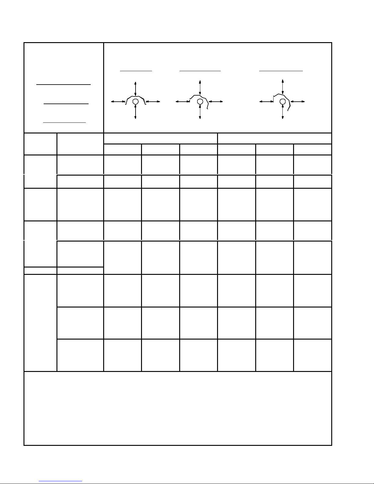
CLEARANCES
APPLICABLE FOR ALL
HEATERS*
Inches (Centimeters)
CLEARANCE TO COMBUSTIBLES*
Top, Front, and Rear clearances are measured from reflector.
Below clearance is measured from bottom of tube.
Clearance to combustibles* measurements are given in inches and (centimeters).
0° MOUNTING 1°-30° MOUNTING 31°-45° MOUNTING
TOP OF REFLECTOR
12 (31)
END OF BURNER
12 (31)
END OF U-BEND
68 (173)
SERIES MBTUH (kW)
40 (12)
45 (13)
A
MB
B
B
B / C 125 (37)
C
50 (15)
55 (16)
60 (18)
65 (19)
70 (21)
75 (22)
80 (23)
85 (25)
90 (26)
95 (28)
100 (29)
105 (31)
110 (32)
115 (34)
120 (35)
130 (38)
135 (40)
140 (41)
145 (42)
150 (44)
155 (45)
160 (47)
165 (48)
170 (50)
175 (51)
180 (53)
185 (54)
190 (56)
195 (57)
200 (59)
FRONT
BELOW
TOP
REAR
REFLECTOR WIDTH = 15.75" (40cm)
FRONT
BELOW
TOP
REAR
FRONT
BELOW
TOP
REAR
0° TO 30° REFLECTOR ANGLE 31° TO 45° REFLECTOR ANGLE
FRONT REAR BELOW FRONT REAR BELOW
40 (102) 40 (102) 40 (102) 40 (102) 12 (31) 40 (102)
50 (127) 50 (127) 50 (127) 50 (127) 12 (31) 50 (127)
24 (61) 24 (61) 60 (152)
24 (61) 24 (61) 60 (152)
32 (82) 32 (82) 72 (183)
48 (122) 48 (122) 82 (209) 70 (189) 12 (31) 82 (209)
58 (148) 58 (148) 92 (234) 80 (203) 12 (31) 92 (234)
68 (173) 68 (173) 102 (259) 90 (229) 12 (31) 102 (259)
*MINIMUM CLEARANCES specified in these tables must be maintained to combustible and other materials which may be
damaged by temperatures 90°F above (50°C above) ambient room temperature. Minimum clearances to combustibles are
also specified on each heater’s serial plate. According to the National Fuel Gas Code (NFPA 54), “in locations used for the
storage of combustible materials, signs must be posted to specify the maximum permissible stacking height to maintain
required clearances from the heater to the combustibles.” Gas supply lines, electrical supply lines, or sprinkler heads shall
not be located within the minimum clearances to combustibles indicated above.
NOTE: Carefully examine surrounding materials near the heater. Materials, such as plastic, having low service
temperature ratings can be discolored or damaged.
GQ pg. 7
•
Between Rows
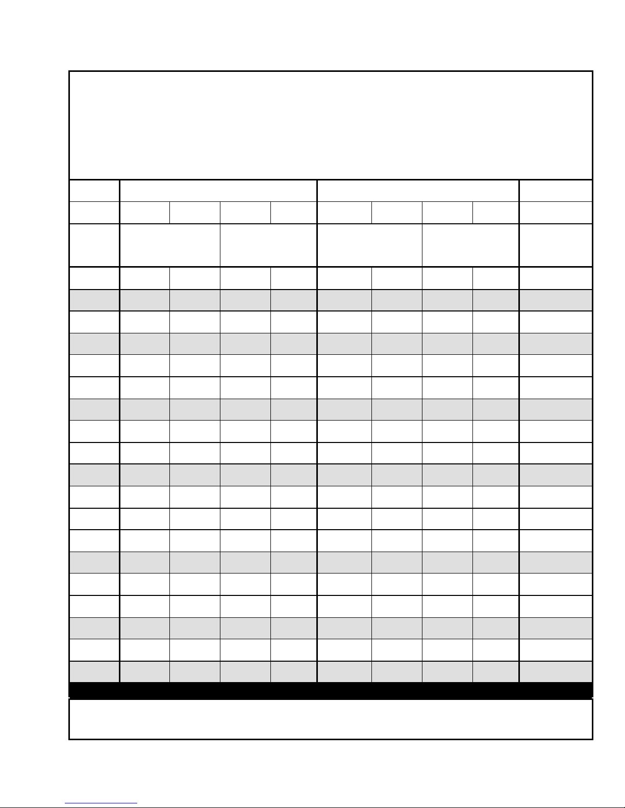
MOUNTING CONSIDERATIONS
• CLEARANCE TO COMBUSTIBLES MUST BE MAINTAINED.
• Mounting heights lower than the recommended Minimum Height may be used if personnel are not
kept directly under heater.
• The Distance From Wall measurement provides the most effective heat dispersion balance
between the floors and walls.
• There is practically no limitation on a maximum mounting height.
By design, a straight infra-red heater will produce more heat at the burner end than at the exhaust
end. Locate the burner end where more heat is desired.
Reflector: Standard Parabolic
Mounting
Angle:
Input
MBTUH
(kW)
40
(12)
45-50
(13-15)
55-60
(16-18)
65-75
(19-22)
80-85
(23-25)
90-95
(26-28)
100-105
(29-31)
110-115
(32-34)
120
(35)
125
(37)
130
(38)
135-140
(40-41)
145
(42)
150
(44)
155-160
(45-47)
165-170
(48-50)
175-180
(51-53)
185-190
(54-56)
195-200
(57-59)
Horizontal 30º - 45º Horizontal 30º - 45º Horizontal 30º - 45º Horizontal 30º - 45º
Minimum Height
(2.9)
10.0
(3.0)
10.5
(3.2)
11.0
(3.4)
11.5
(3.5)
12.0
(3.7)
12.5
(3.8)
13.0
(4.1)
13.5
(4.1)
14.0
(4.3)
14.5
(4.4)
15.0
(4.6)
15.5
(4.7)
16.0
(4.9)
16.5
(5.0)
17.0
(5.2)
17.5
(5.3)
18.0
(5.5)
18.5
(5.6)
9.5
ft
(m)
7.5
(2.3)
8.0
(2.4)
8.5
(2.6)
9.0
(2.7)
9.5
(2.9)
10.0
(3.0)
10.5
(3.2)
11.0
(3.4)
11.5
(3.5)
12.0
(3.7)
12.5
(3.8)
13.0
(4.0)
13.5
(4.1)
14.0
(4.3)
14.5
(4.4)
15.0
(4.6)
15.5
(4.7)
16.0
(4.9)
16.5
(5.0)
Distance From Wall
6
(1.8)
6
(1.8)
6
(1.8)
8
(2.4)
8
(2.4)
8
(2.4)
8
(2.4)
12
(3.7)
12
(3.7)
12
(3.7)
12
(3.7)
12
(3.7)
12
(3.7)
12
(3.7)
13
(4.0)
13
(4.0)
14
(4.3)
14
(4.3)
15
(4.6)
ft
(m)
1
(0.3)
1
(0.3)
1
(0.3)
1
(0.3)
1
(0.3)
1
(0.3)
1
(0.3)
1
(0.3)
1
(0.3)
1
(0.3)
1
(0.3)
1
(0.3)
1
(0.3)
1
(0.3)
1
(0.3)
1
(0.3)
1
(0.3)
1
(0.3)
1
(0.3)
Minimum Height
11.5
(3.5)
12.0
(3.7)
12.5
(3.8)
13.0
(4.0)
13.5
(4.1)
14.0
(4.3)
14.5
(4.4)
15.0
(4.6)
15.5
(4.7)
16.0
(4.9)
16.5
(5.0)
17.0
(5.2)
17.5
(5.3)
18.0
(5.5)
18.5
(5.6)
19.0
(5.8)
19.5
(5.9)
20.0
(6.1)
20.5
(6.2)
ft
(m)
9.5
(2.9)
10.0
(3.0)
10.5
(3.2)
11.0
(3.4)
11.5
(3.5)
12.0
(3.7)
12.5
(3.8)
13.0
(4.1)
13.5
(4.1)
14.0
(4.3)
14.5
(4.4)
15.0
(4.6)
15.5
(4.7)
16.0
(4.9)
16.5
(5.0)
17.0
(5.2)
17.5
(5.3)
18.0
(5.5)
18.5
(5.6)
Distance From Wall
HIGH ALTITUDE
4
(1.2)
4
(1.2)
4
(1.2)
6
(1.8)
6
(1.8)
6
(1.8)
6
(1.8)
9
(2.7)
9
(2.7)
9
(2.7)
9
(2.7)
9
(2.7)
9
(2.7)
9
(2.7)
10
(3.0)
10
(3.0)
11
(3.4)
11
(3.4)
12
(3.7)
ft
(m)
1
(0.3)
1
(0.3)
1
(0.3)
1
(0.3)
1
(0.3)
1
(0.3)
1
(0.3)
1
(0.3)
1
(0.3)
1
(0.3)
1
(0.3)
1
(0.3)
1
(0.3)
1
(0.3)
1
(0.3)
1
(0.3)
1
(0.3)
1
(0.3)
1
(0.3)
Standard &
Parabolic
Horizontal &
30º - 45º
Max. Distance
ft
(m)
80
(24.4)
80
(24.4)
80
(24.4)
80
(24.4)
90
(27.4)
95
(29.0)
95
(29.0)
100
(30.5)
100
(30.5)
105
(32.0)
105
(32.0)
105
(32.0)
105
(32.0)
105
(32.0)
105
(32.0)
110
(33.5)
110
(33.5)
115
(35.1)
115
(35.1)
If a heater is to be installed at a high altitude, in excess of two thousand feet (610 m) above sea level,
consult the factory (U.S. & CANADA).
GQ pg. 8
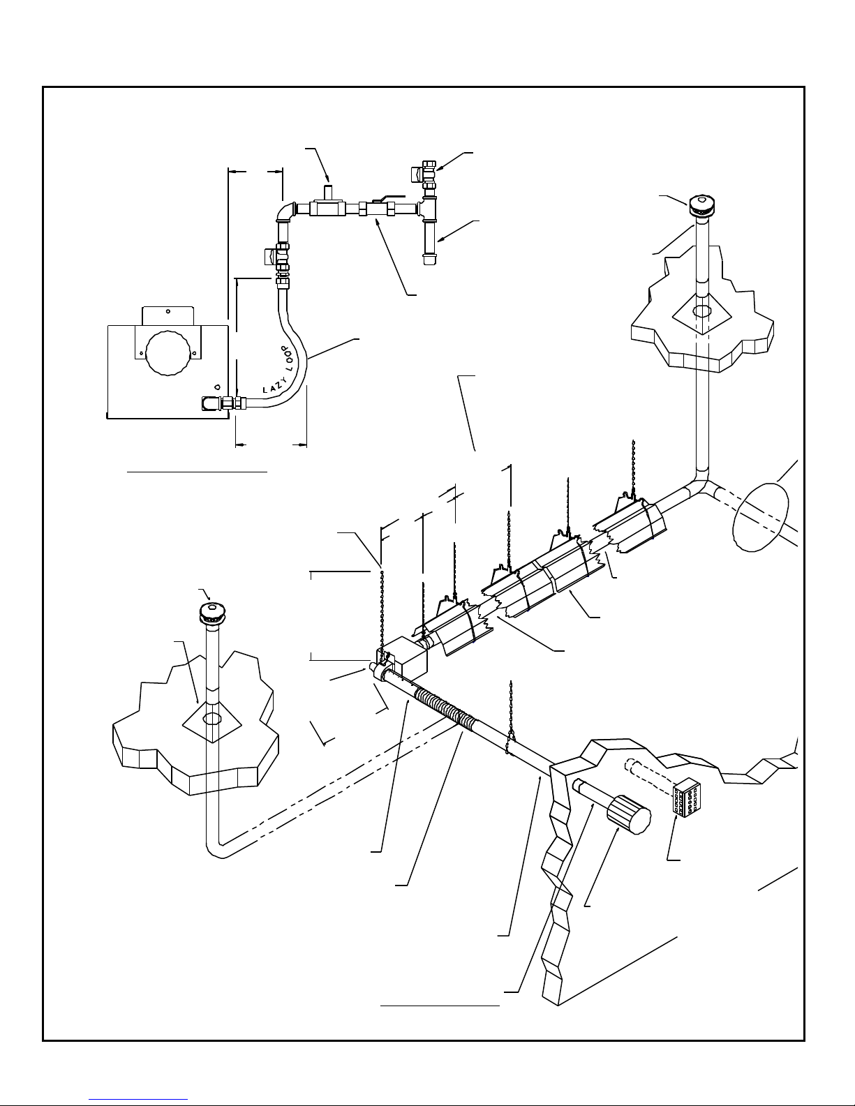
OVERVIEW DRAWINGS (1 OF 2)
WHEN GAS PRESSURE EXCEEDS
14" (35cm) W.C., A FIRST STAGE
REGULATOR MUST BE INSTALLED
5"
(13cm)
15"
(38cm)
6.5"
(17cm)
GAS CONNECTION DIAGRAM
ALL HANGING CHAINS MUST BE PLUMB
AND VERTICAL IN ALL DIRECTIONS WHEN
VENT CAP
MUST BE
6 IN. (15cm)
HIGHER THAN
SNOW DEPTH
ROOF
FLASHING
(NOT
SUPPLIED)
INITIALLY INSTALLED
DISTANCE FROM
SUSPENSION POINT
TO TOP OF COVER
PLUS 6" (15cm)
SLACK = LENGTH OF
SAFETY CHAIN
BURNER
1/2" (1.27cm) O.D.
FLEXIBLE GAS
CONNECTOR
24" (61cm) LONG
STAINLESS STEEL
12"(30cm) MIN.
CLEARANCE
GAS COCK
(SUPPLIED BY OTHERS)
4 FT. (1.2m)
29 IN.
(74cm)
12 IN.
(31cm)
17 IN.
(43cm)
LOCAL CODES MAY REQUIRE
AN ADDITIONAL SHUT-OFF
COCK BE INSTALLED IN THE
GAS LINE AHEAD OF THE DRIP LEG
VENT CAP MUST BE
6" (15cm) HIGHER
THAN SNOW DEPTH
DRIP LEG
"B" VENT
PIPE ADAPTOR
HANGER BRACKETS MUST BE
SPACED AT LEAST 4 FT. (1.2m) APART
WITH (2) BRACKETS FOR EVERY
SECTION OF RADIANT TUBING
MIN.
8FT.
(2.4m)
MAX.
HEAT EXCHANGER 4 IN.
(10.2cm) O.D. X 5 OR 10 FT.
(1.5m OR 3.0m) LONG
REFLECTOR
INDEPENDENTLY ADJUSTABLE
COMBUSTION CHAMBER
4 IN. (10.2cm) O.D. X 10 FT. (3m) LONG
ADDITIONAL COMBUSTION AIR SUPPLY
SINGLE WALL 26 GA. (.044cm) MINIMUM
GALVANIZED SHEET METAL PIPE OR
SCHEDULE 40 PVC (SEAM TO BE AT TOP)
(NOT SUPPLIED)
2 FT. (61cm) MINIMUM
CLEARANCE ABOVE OR
BEYOND THE HIGHEST
STRUCTURE OF
SURFACE WITHIN
10 FT. (3m)
OF THE VENT
INLET AIR SLEEVE
(SEAM TO BE ON TOP)
4 IN. (10.2cm) I.D. FLEX DUCT
18 IN. (46cm) LONG WITH
SUPPLY PIPING MUST NOT EXCEED AN EQUIVALENT
OF 35 LINEAR FT. (10.7m) FOR 40-125 MBTUH (12-37kW)
OR 40 LINEAR FT. (12.2m) FOR 130-200 MBTUH (38-59kW).
NO MORE THAN TWO 90° ELBOWS MAY BE USED.
A 90° ELBOW IS EQUIVALENT TO 10 LINEAR FT. (3m).
(2) HOSE CLAMPS
(PROVIDED BY OTHERS)
4" B-VENT ADAPTOR
INLET AIR CAP
(OPTIONAL
ACCESSORY)
INLET AIR BOX
(ALTERNATE
OPTIONAL
ACCESSORY)
USE APPROPRIATE
FASTENERS
(NOT SUPPLIED)
OVERVIEW DRAWINGS (2 OF 2)
GQ pg. 9
BURNER
SAFETY
CHAIN
BURNER
FINAL
SUSPENSION
POINT
MAINTAIN 18 IN. (46cm) MINIMUM
CLEARANCE TO COMBUSTIBLES
FOR ENTIRE LENGTH OF PIPING
ADDITIONAL EXHAUST VENT PIPING 4" (10.2cm) I.D.
SINGLE WALL 26 GA. (.044cm) MINIMUM GALVANIZED
SHEET METAL (OR OTHER FACTORY-APPROVED
MATERIALS) (SEAM TO BE ON TOP) (NOT SUPPLIED)
MUST NOT EXCEED AN EQUIVALENT OF 35 LINEAR FT.
(10.7m) FOR 40-125 MBTUH (12-37kW) OR 40 LINEAR
FT. (12.2m) FOR 130-200 MBTUH (38-59kW). NO MORE
THAN 2 ELBOWS MAY BE USED. A 90° ELBOW IS
EQUIVALENT TO 10 LINEAR FT. (3m). A 45° ELBOW IS
EQUIVALENT TO 5 LINEAR FT. (1.5m).
2 FT. (61cm) MIN.
WALL BRACE
REFLECTOR
FLOW OF HOT GASES
SUSPENSION BRACKET
AROUND BURNER
COUPLER
4"(10.2cm)
VENT CAP
ASSEMBLY
WALL
VENTING
KIT
OPTIONAL COMMON VENTING THROUGH ROOF OR WALL
TUBE WELD SEAM
ON TOP
HEAT EXCHANGER MOUNTING ARRANGEMENT
#12 TEK SCREW
4 PLACES
BURNER
BURNER COUPLER MOUNTING ARRANGEMENT
#12 TEK SCREW
WELD SEAM TO BE AT TOP
COMBUSTION CHAMBER
BURNER COUPLER
FOR ALL JOINTS RTV
SILICONE ADHESIVE
SEALANT SHOULD BE
USED TO PREVENT
LEAKAGE OF HOT
FLUE GASSES.
4" x 4" x 5" Y-COUPLER
(10 x 10 x 13cm) (OPTIONAL ACCESSORY)
BOTH HEATERS MUST BE CONTROLLED
BY A SINGLE THERMOSTAT
TUBE WELD SEAM
ON TOP
3.0" (7.6cm) MIN.
4.0" (10.2cm) MAX.
NEVER USE
A STRAIGHT
THROUGH TEE
USE APPROPRIATE FASTENER (NOT SUPPLIED)
FOR ATTACHING TO BUILDING MATERIAL
FOR ALL INDOOR VENT JOINTS: USE RTV SEALANT TO PREVENT HOT FLUE GAS LEAKAGE INTO THE
BUILDING (USE A SHEET METAL PIPE AND CRIMPER FOR JOINING IDENTICAL SIZE SHEET METAL PIPES),
USE THREE (3) #6 SHEET METAL SCREWS (SMS) PER VENT PIPE JOINT. THE VENT PIPE SEAM SHOULD
BE ON TOP WITH ONE SMS ON TOP AND ONE SMS 120 DEGREES FROM THE TOP ON EACH SIDE.
(3) 90 DEGREE BRACES EQUALLY SPACED
FOR COMBUSTIBLE WALLS ONLY USE A 2" (5.1cm) CLEARANCE NON-COMBUSTIBLE VENTILATING
METAL THIMBLE (NOT SUPPLIED). FOR NON-COMBUSTIBLE WALLS ONLY 4.25" (10.8cm) DIA. HOLE FOR
4" (10.2cm) O.D. PIPE ADD NON-COMBUSTIBLE PROTECTION AROUND THE HOLE IF NECESSARY.
CAUTION
• The first twenty (20) feet (6.1 m) of radiant tube extending from the burner
MUST be installed straight.
• There is one exception. A U-Tube heater may have a 180 degree U-bend
interposed AFTER the first ten (10) feet (3.0 m).
• Electrical wiring diagrams can be found in the ELECTRICAL SUPPLY
AND THERMOSTATIC CONTROL section.

GQ pg. 10
4" (10cm)
HEATER CONFIGURATIONS
Low-intensity heaters can be arranged in many configurations; some common ones are illustrated below. It
is important to limit the number of bends since each bend slows the movement of air inside the tube,
resulting in decreased efficiency.
1. The first twenty feet (6.1 m) of radiant tube extending from the burner must be installed straight
[EXCEPTION: a 15 foot (4.6 m) or 20 foot (6.1 m) heater may have a 180° U-bend interposed after the
first 10 feet (3.0 m)].
2. Each system can use a maximum of two (2) 16 gauge (.17 cm) aluminized steel 90° elbows, OR one
(1) 16 gauge (.17 cm) aluminized steel 180° U-bend. Elbows and U-bends can not be used
simultaneously in the same system.
3. All tube sections of a unit must be mounted on the same horizontal plane. For exceptions or other
configurations, consult factory.
4. Special reflectors are available: 90° elbow reflector, 180° U-bend reflector, side extension reflector and
inverted V-deflectors. Contact factory for more information.
5. Use factory accessory elbows and U-bends only.
180° U-BEND 90° ELBOW
16"
(41cm)
6" (15cm)
TYP.
4" (10cm)
OD TYP.
20"
(51cm)
CONFIGURATION DIAGRAMS
12" (30cm) TYP.
OD
4"
(10cm)
TYP.
Note: Not all units can utilize every configuration.

GQ pg. 11
BASIC SYSTEM CONFIGURATIONS
GQ system Combustion Chamber, Heat Exchanger and Exhaust End components all have a GQ prefix, i.e. GQC9.
NOTE: These are the recommended configurations for your heater. Contact the factory with any questions.
LEGEND: L : LP/Propane gas, N : Natural gas, 4 : Burner, U : 180° U-Bend.
STRAIGHT TUBE HEATER COMPONENTS
Burner Size
MBTUH (kW)
40 (12) 10 (3.1) A N/L
40 (12) 15 (4.6) A N/L
40 – 60 (12 – 18) 20 (6.1) A N/L
65 – 85 (19 – 25) 20 (6.1) MB N(L)
65 – 85 (19 – 25) 25 (7.6) MB N(L)
65 – 100 (19 – 29) 30 (9.1) B N(L)
65 – 100 (19 – 29) 35 (10.6) B N(L)
65 – 100 (19 – 29) 40 (12.2) B N(L)
105 – 120 (31 – 35) 40 (12.2) B N/L
125 (37) 40 (12.2) B N - only
125 (37) 40 (12.2) C L - only
130 – 150 (38 – 44) 40 (12.2) C N/L
100 (29) 45 (13.7) B N(L)
105 – 120 (31 – 35) 45 (13.7) B N/L
125 (37) 45 (13.7) B N - only
125 (37) 45 (13.7) C L - only
130 – 150 (38 – 44) 45 (13.7) C N/L
100 (29) 50 (15.2) B N(L)
105 – 120 (31 – 35) 50 (15.2) B N/L
125 (37) 50 (15.2) B N - only
125 (37) 50 (15.2) C L - only
130 – 200 (38 – 59) 50 (15.2) C N/L
150 – 200 (44 – 59) 55 (16.8) C N/L
150 – 200 (44 – 59) 60 (18.3) C N/L
150 – 200 (44 – 59) 65 (19.9) C N/L
150 – 200 (44 – 59) 70 (21.3) C N/L
Length
Ft (m)
Series
Gas
Type
4
4
4
4
4
4
4
4
4
4
4
4
4
4
4
4
4
4
4
4
4
4
4
4
4
4
4
Combustion
Chamber
C9 ---- ---C9 ---- H6
C1 ---- H1
C2 ---- H9(H1)
C2 H6 H9(H1)
C2(C3) H2 H5
C2(C3) H2 H6 H5
C2(C3) H2 H2 H5
C4 H2 H2 H5
C4 H2 H2 H5
C4 H2 H2 H5
C4 H2 H2 H5
C2(C3) H2 H2 H6 H5
C4 H2 H2 H6 H5
C4 H2 H2 H6 H5
C4 H2 H2 H6 H5
C4 H2 H2 H6 H5
C2(C3) H2 H2 H2 H5
C4 H2 H2 H6 H5
C4 H2 H2 H6 H5
C4 H2 H2 H2 H5
C4 H2 H2 H2 H5
C4 H2 H2 H2 H6 H5
C4 H2 H2 H2 H2 H5
C4 H2 H2 H2 H2 H6 H5
C4 H2 H2 H2 H2 H2 H5
Heat Exchangers
Exhaust
End
U-TUBE
Burner Size
MBTUH (kW)
40 (12) 15 (4.6) A N/L
40 – 60 (12 – 18) 20 (6.1) A N/L
65 – 85 (19 – 25) 20 (6.1) MB N(L)
65 – 100 (19 – 29) 30 (9.1) B N(L)
65 – 100 (19 – 29) 40 (12.2) B N(L)
105 – 120 (31 – 35) 40 (12.2) B N/L
125 (37) 40 (12.2) B N - only
125 (37) 40 (12.2) C L - only
130 – 150 (38 – 44) 40 (12.2) C N/L
100 (29) 50 (15.2) B N(L)
105 – 120 (31 – 35) 50 (15.2) B N/L
125 (37) 50 (15.2) B N - only
125 (37) 50 (15.2) C L - only
130 – 200 (38 – 59) 50 (15.2) C N/L
150 – 200 (44 – 59) 60 (18.3) C N/L
150 – 200 (44 – 59) 70 (21.3) C N/L
Length
Ft (m)
Series
Gas
Type
4
4
4
4
4
4
4
4
4
4
4
4
4
4
4
4
4
HEATER COMPONENTS
Combustion
Chamber
C9 U H6
C1 U H1
C2 U H9(H1)
C2(C3) H6 U H6 H5
C2(C3) H2 U H2 H5
C4 H2 U H2 H5
C4 H2 U H2 H5
C4 H2 U H2 H5
C4 H2 U H2 H5
C2(C3) H2 H6 U H6 H2 H5
C4 H2 H6 U H6 H2 H5
C4 H2 H6 U H6 H2 H5
C4 H2 H6 U H6 H2 H5
C4 H2 H6 U H6 H2 H5
C4 H2 H2 U H2 H2 H5
C4 H2 H2 H6 U H6 H2 H2 H5
Heat Exchangers
Exhaust
End

GQ pg. 12
GQC9
COMBUSTION CHAMBERS
40 MBTUH (10 and 15 ft. units only)
[12 kW (3 and 4.6m only)]
EXHAUST END
(STENCILED ON TUBE)
TURBULATOR
(FACTORY
INSTALLED)
WHITE TAPE
40 thru 60 MBTUH (20 ft. unit only)
[12-18 kW (6.1m only)]
GQC1
BURNER END
(STENCILED ON TUBE)
GQC2
BURNER END
(STENCILED ON TUBE)
GQC4
• 10 ft. (3m), 14 ga. (.21cm)
aluminized titanium alloy steel
tube with C9-turbulator
• 10 ft. (3m) aluminum reflector
• (2) hanger brackets
65 thru 85 MBTUH (20 and 25 ft. MB units
only) [19-25 kW (6.1 and 7.6m MB only)] 65
thru 100 MBTUH (30 thru 50 ft. natural gas
units) [19-29 kW (9.1-15.2m natural gas)]
• 10 ft. (3m), 16 ga. (.17cm)
aluminized titanium alloy steel
tube
• 10 ft. (3m) aluminum reflector
• (2) hanger brackets
105 thru 200 MBTUH (40 thru 70 ft. units
only) [31-59 kW (12.2-21.3m units only)]
• 10 ft. (3m), 16 ga. (.17cm)
aluminized titanium alloy steel
BURNER END
(STENCILED ON TUBE)
tube
• 10 ft. (3m) aluminum reflector
• (2) hanger brackets
65 thru 100 MBTUH (30 thru 50 ft. propane
gas units) [19-29 kW (9.1-15.2m propane
GQC3
BURNER END
(STENCILED ON TUBE)
gas)]
INNER LINER
• 10 ft. (3m), 16 ga.(.17cm)
aluminized titanium alloy steel
tube with inner liner
• 10 ft. (3m) aluminum reflector
• (2) hanger brackets
10 ft. (3m) aluminum reflector [length approx. 119” (302cm)]
• 10 ft. (3m), 14 ga. (.21cm)
aluminized titanium alloy steel
tube painted black
BURNER END
(STENCILED ON TUBE)
• 10 ft. (3m) aluminum reflector
• (2) hanger brackets
Hanger Bracket

GQH2
HEAT EXCHANGERS
MIDDLE HEAT EXCHANGER COMPONENTS
65 thru 200 MBTUH (30 thru 70 ft. units)
[19-59 kW (9.1-21.3m)]
GQH6
GQ pg. 13
40 MBTUH (ONLY 15 ft. end tube)
[12 kW (ONLY 4.6m end tube)]
65 thru 200 MBTUH (25 thru 70 ft. units)
[19-59 kW (7.6-21.3m)]
GQH1
GQH9
• 10 ft. (3m), 16 ga. (.17cm)
aluminized steel tube
• 10 ft. (3m) aluminum reflector
• (2) hanger brackets
EXHAUST END HEAT EXCHANGER COMPONENTS
40 thru 60 MBTUH (20 ft. unit) [12-18 kW
(6.1m)], 65 thru 85 MBTUH (20 and 25 ft.
propane MB units) [19-25 kW (6.1 and 7.6m
propane MB units)]
EXHAUST END
(STENCILED ON TUBE)
TURBULATOR
(FACTORY
INSTALLED)
• 10 ft. (3m), 16 ga. (.17cm)
aluminized steel tube with H1turbulator
• 10 ft. (3m) aluminum reflector
• (2) hanger brackets
65 thru 85 MBTUH (20 and 25 ft. natural gas
MB units) [19-25 kW (6.1 and 7.6m natural
gas MB units)]
• 5 ft. (1.5m), 16 ga. (.17cm)
aluminized steel tube
• 5 ft. (1.5m) aluminum reflector
• (2) hanger brackets
65 thru 200 MBTUH (excluding 20 and 25 ft.
GQH5
10 ft. (3m) reflector [length approx. 119” (302cm)]
MB units) [19-59 kW (excluding 6.1 and
7.6m MB units)]
EXHAUST END
(STENCILED ON TUBE)
• 10 ft. (3m), 16 ga. (.17cm)
aluminized steel tube with H5turbulator
• 10 ft. (3m) aluminum reflector
• (2) hanger brackets
TURBULATOR
(FACTORY
INSTALLED)
• 10 ft. (3m), 16 ga. (.17cm)
aluminized steel tube with H9turbulator
• 10 ft. (3m) aluminum reflector
• (2) hanger brackets
EXHAUST END
(STENCILED ON TUBE)
TURBULATOR
(FACTORY
INSTALLED)
WHITE TAPE
Hanger Bracket

GQ pg. 14
COMBUSTION AIR SUPPLY
GENERAL NOTES MAXIMUM LENGTHS OF AIR SUPPLY PIPE
• Atmospheric air for combustion may come
from either outdoors or indoors (from within
the building).
• Installation of combustion air supply must
comply with the instructions, drawings, and
installation notes provided in this section.
OUTDOOR AIR SUPPLY THRU-THE-WALL (OUTDOORS)
• Atmospheric air for combustion may come
from either outdoors or indoors (from within
the building).
• Installation of combustion air supply must
comply with the instructions, drawings, and
installation notes provided in this section.
• In buildings contaminated with excessive dust
or dirt, or containing substances which when
combined with flame and exhaust products
result in corrosive gasses or those under a
negative pressure, or high humidity areas,
combustion air must come from outdoors.
• Outdoor air supply may be accomplished by
bringing in air through piping from either the
roof or wall as the drawings illustrate.
• When combustion air is supplied from
outdoors, the heater must also be vented to
the outdoors (EXCEPT high humidity
environments consult factory).
• The roof venting cap used for inlet air cap
(roof), inlet air wall cap or inlet air box (wall)
must be located at least three (3) feet (.91 m)
away from any vent termination and in a
manner to prevent blockage by snow.
• Components supplied by others must be
identical to those specified in this manual and
be Metalbestos brand, or equal. NO
SUBSTITUTIONS.
• Single wall 4” (10.2 cm) I.D., 26-gauge (.044
cm) minimum stainless or galvanized sheet
metal pipe or schedule 40 PVC is
recommended for combustion air supply
piping.
• It may be desirable to insulate piping with 1
inch (2.54 cm) of pipe insulation to eliminate
condensation from warm inside air.
• DO NOT use collapsible material for
combustion air supply, as it will restrict the
proper amount of combustion air from being
supplied to the burner.
• An optional blower enclosure extends the
burner housing to enclose the blower. The
outdoor air piping is then attached to the
enclosure, isolating the outside of the blower
and motor from contaminants.
INDOOR AIR SUPPLY
• When combustion air is to be taken from
inside a tightly closed building, an opening
must be installed to supply the burner with
sufficient air for combustion.
• For every 4,000 BTUH (1.17 kW) input of the
total input of ALL gas-fired equipment, one (1)
square inch (6.45 cm2) or more of free area
opening must be provided.
• The openings should be located above the
heaters to reduce the effect of drafts.
• Do not draw combustion air into the heater
from attic space. There is no guarantee
adequate air will be supplied
40 TO 125 MBTUH (12 – 37 kW) 35 linear ft. (10.7 m)*
130 TO 200 MBTUH (38 – 59 kW) 40 linear ft. (12.2 m)*
*Each 90 degree elbow inserted in the venting system
*Each 45 degree elbow inserted in the venting system
A maximum of two 90 degree elbows or their equivalent are allowed (e.g. one 90
degree elbow plus two 45 degree elbows; or four 45 degree elbows, etc.)
is equivalent to 10 linear ft. (3.0 m).
is equivalent to 5 linear ft. (1.5 m).
OPTIONAL INLET AIR SLEEVE
(SEAM TO BE AT TOP)
FLEX DUCT 4 IN. (10 CM) I.D.
18 IN. (46 CM) LONG
ADDITIONAL COMBUSTION AIR
SUPPLY PIPING 4 IN. (10 CM) I.D.
(NOT INCLUDED)
SUPPORT AS NEEDED.
INLET AIR
COLLAR
TWO HOSE CLAMPS
INLET AIR BOX
(ALTERNATE
OPTIONAL
INLET AIR WALL CAP
(OPTIONAL ACCESSORY)
REQUIRES 4" B-VENT ADAPTOR
(PROVIDED BY OTHERS)
ACCESSORY)
USE APPROPRIATE
FASTENERS
(NOT SUPPLIED)
THRU-THE-ROOF (OUTDOORS)
ROOF VENTING CAP USED FOR INLET AIR MUST BE
6 IN. (15 CM) HIGHER THAN SNOW DEPTH.
INLET
AIR COLLAR
ROOF VENTING
CAP 4 IN.
(10 CM) I.D.
OPTIONAL
INLET AIR
SLEEVE (SEAM
TO BE AT TOP)
FLEXIBLE DUCT
4 IN (10 CM) I.D.
ADDITIONAL COMBUSTION AIR
SUPPLY PIPING 4 IN. (10 CM) I.D.
(NOT INCLUDED)
SUPPORT AS NEEDED.

ROOF VENTING CAP MUST BE 6 IN. (15 CM) HIGHER THAN SNOW DEPTH.
EXHAUST VENTING
VENTING KIT
INDIRECT INDOOR VENTING INSIDE OF BUILDING
GQ pg. 15
• A heater that is vented indoors is classified as
Category I by the National Fuel Gas Code.
• At least 4 CFM of exhaust per 1,000 BTUH (.38 m
per minute per kW) must be provided. Supply and
exhaust air must be provided by natural or
mechanical means. For Canada see CANADIAN
ADDENDUM section.
• For supply and exhaust air by natural means, fresh
air/ exhaust openings are required.
• Fresh air openings should be below the indoor
venting kit.
• Exhaust openings must be located above the
heaters.
• For supply and exhaust air by mechanical means,
provision must be made so the flow of gas to the
heater is allowed only when the mechanical
exhaust is in operation.
• Combustion air must not be provided directly from
outdoors to the inlet air collar on the burner. (For
exceptions see COMBUSTION AIR SUPPLY).
DIRECT OUTDOOR VENTING
• A heater vented directly outdoors is classified as
Category III by the National Fuel Gas Code.
• It may be vented through either the roof or wall
singularly or in conjunction with no more than one
other heater with a single thermostat. To commonly
vent more than two heaters consult the factory.
• Use 4 in. (10.2 cm) I.D. single wall stainless or
galvanized sheet metal pipe of not less than 26
gauge (.044 cm) (or other factory approved
materials). Place seam at the top.
• Use RTV silicone adhesive sealant liberally at all
vent pipe joints.
• Use three (3) #6 sheet metal screws per vent pipe
joint – 120° apart starting on top.
• 1 inch (2.5 cm) thick pipe insulation wrapped
around the single wall sheet metal pipe is
recommended.
• By code, the use of dual wall pipe for outdoor
venting is limited to appliances with neutral or
negative pressures. Local authorities may waive
this provision since the heaters are approved for
indoor venting with proper exhaust and leakage
due to condensation being greatly reduced.
• Be certain to get approval for either type of vent
piping from local authorities.
• Vent pipes must be well supported due to the extra
stress that occurs during expansion of the unit
when operating.
• Vent caps must be identical, or equal, to those
specified in this manual which are of the
Metalbestos brand. This is critical to the heater’s
operation and to maintain C.S.A. certification.
• Heater must not be vented in between buildings
less than 10 feet (3.0 m) apart or above public
walkways, doors or windows.
MORE INFORMATION
CLEARANCE TO COMBUSTIBLES (CTC) MUST BE MAINTAINED FROM
EXHAUST END OF HEATER.
3
RATING
MBTUH (kW) CTC*
COMBUSTIBLE
OBJECTS MUST
NOT BE WITHIN
RADIUS OF CTC
40 to 60 (12 - 18) 10” (25 cm)
65 to 100 (19 - 29) 30” (76 cm)
105 to 125 (31 - 37) 38” (97 cm)
130 to 150 (38 - 44) 48” (122 cm)
155 to 175 (45 - 51) 58” (147 cm)
180 to 200 (53 - 59) 68” (173 cm)
*CTC is measured from
the end of the Indoor
INDOOR
CTC
Venting Kit.
Minimum clearance from ceiling: 15” (38 cm) is measured from top of reflector.
THROUGH THE WALL AND ROOF
ROOF VENTING CAP
B VENT PIPE
ADAPTOR
ROOF FLASHING
(NOT SUPPLIED)
(3) 90° BRACES
EQUALLY
SPACED
MAINTAIN 18 IN. (46 CM) MINIMUM
CLEARANCE TO COMBUSTIBLES
FOR ENTIRE LENGTH OF PIPING
ADDITIONAL 4 IN. (10 CM)
EXHAUST VENT PIPING
(NOT SUPPLIED)
ROOF
VENTING
CAP
4 IN.
(10 CM)
VENT PIPE
A'SSY
WALL BRACE
DISTANCES OF EXHAUST VENT FROM:
BELOW
Inches (cm)
Door N/A 48 (122) N/A
Window 48 (122) 12 (30) N/A
Gravity Air Inlet N/A N/A 12 (30)
Forced Air Inlet
Within 10 ft. (3.0 m)
N/A N/A 36 (91)
Grade N/A N/A 12 (30)
Gas & Electric Meters,
Regulators & Relief Valves
N/A 48 (122) N/A
HORIZONTAL
Inches (cm)
ABOVE
Inches (cm)
MAXIMUM LENGTHS OF VENT PIPE
40 TO 125 MBTUH (12 – 37 kW) 35 linear ft. (10.7 m)*
130 TO 200 MBTUH (38 – 59 kW) 40 linear ft. (12.2 m)*
• See the OVERVIEW DRAWINGS section for more
venting information
*Each 90 degree elbow inserted in the venting system
is equivalent to 10 linear ft. (3.0 m).
*Each 45 degree elbow inserted in the venting system
is equivalent to 5 linear ft. (1.5 m).
A maximum of two 90 degree elbows or their equivalent are allowed (e.g. one 90
degree elbow plus two 45 degree elbows; or four 45 degree elbows, etc.)

GQ pg. 16
WINDY CONDITIONS NOTES
VIEW A
VIEW A
HANGER
KEPS NUT
NEAR LOADING DOCK, AIRPLANE HANGAR DOORS,
OR OTHER WINDY AREAS FASTEN REFLECTORS
TO HANGERS WITH LOOP STRAPS, SCREWS AND
KEPS NUTS.
NO LESS THAN 20 FT(6.1m)
EXCEPT 10 & 15 FT.
(3m & 4.6m) MODELS
STRAIGHT OR 'L'
CONFIGURATION
SCREW
LOOP STRAP
REFLECTOR
OVERHEAD VIEW
HANGERS MUST BE
STAGGERED FOR A
U-TUBE HEATER
SUSPENDED FOR
WINDY CONDITIONS
'U' TUBE
CONFIGURATION

GQ pg. 17
U-TUBE INSTALLATION
• A heater may be installed as a U-Tube with its radiant tubes horizontal or with the heat exchanger
angled above the combustion chamber as illustrated by the drawing below.
• When radiant tubes are horizontal, reflectors may be individually rotated from 0 to 30 degrees or
from 0 to 45 degrees depending on the model installed. (Refer to CLEARANCE TO
COMBUSTIBLES section).
HORIZONTAL
ANGLED
U-BEND
REFLECTOR
(OPTIONAL)
DO NOT
EXCEED
7.5"
(19CM)
U-BEND REFLECTOR
(OPTIONAL)

GQ pg. 18
TUBE ASSEMBLY TIPS (1 OF 2)
Experienced installers have made recommendations to
simplify the installation of these tubes by reducing the
number of connections to be made up in the air
Most important:
• Do not drag the tubes and dent the connecting ends!
• ALIGN THE WELD SEAMS OF ALL THE TUBES and make
sure they are on top when joining tubes!
COLOR INSERTION INDICATOR
ALL WELD SEAMS
MUST BE LINED UP
TOGETHER
SWAGED END
AIR FLOW
#1
Place two (2) ten (10) foot (3m) sections on the floor and align
PILOT HOLE
FLARED END
the weld seams on top. (Properly orient the “BURNER
END”/”EXHAUST END” markings on the combustion and exhaust
end tubes).
ALIGN ALL THE WELD SEAMS IN A LINE TOGETHER!
WELD
SEAM
WOOD BLOCK
2X4 IN. (5X10 CM)
STURDY WALL
SWAGED END
COLOR INSERTION INDICATOR
PILOT HOLE
FLARED END
2X4 IN. (5X10 CM)
WELD
SEAM
WOOD BLOCK
#2
Position a 2X4 in. (5x10 cm) block of wood on each of the far
ends of both tubes.
• One block of wood prevents damage to the connecting end that
will be used to tap that tube into the other.
• The other block of wood prevents damage to the other
connecting end that is butted up to a nearby sturdy wall.

TUBE ASSEMBLY TIPS (2 OF 2)
Manually slide the male end of one tube into the female end of
#3
the other tube. ALIGN THE WELD SEAMS ON BOTH TUBES
TOGETHER. STRAIGHTEN the two (2) tubes and proceed to tap
one tube into the other by hitting the wooden 2X4 in. (5x10 cm)
block, NOT the tube! Continue to tap one tube into the other until
the flared end comes up to, but does not cover the color insertion
indicator.
STRAIGHTEN BEFORE DRIVING SCREWS
WRONG - NOT STRAIGHT
RIGHT - STRAIGHT
GQ pg. 19
#4
STRAIGHTEN the tubes again BEFORE driving the
screws. Ensure all tubes are straight and level with the weld
seam on top before installing the screws. Drive with a power too l
the two (2) #12 MULTI-METAL Tek screws into the joint and
position the four (4) hangers on the twenty (20) foot (6.1m)
section.
#5
Attach a temporary rope or chain to the two (2) outer brackets
and hoist the twenty (20) foot (6.1m) section into the air. Align the
weld seam on top, level the section, and install the chain on the
hangers.
#6
Repeat the steps for the next section(s) of tube and hoist it
into the air. Use the temporary ropes/chains to maneuver the two
(2) twenty (20) foot (6.1m) sections together as close as possible.
ALIGN THE WELD SEAMS OF BOTH SECTIONS TOGETHER
ON TOP, leve l the sec ond section, and a pply th e cha in to t he four
(4) hangers. With the first twenty (20) foot (6.1m) section secured,
use a hammer tapping on a wooden 2X4 in. (5x10 cm) block to
join both sections together, followed by the two (2) screws.
Complete the total installation according to this manual. Use these
tips along with the instructions in the INSTALLATION section. Use
the WINDY CONDITIONS NOTES and the U-TUBE
INSTALLATION sections as necessary.

GQ pg. 20
INSTALLATION (1 OF 2)
CAUTION
• DO NOT use gas piping or electrical conduit to provide any type of support for the heater’s suspension.
• Means of suspension MUST BE able to support twice the weight of the heater, securely fastened to the building’s
structure, and allow for expansion during its operation.
• Chain for suspension MUST BE 12 in. (31cm) minimum in length and be 1/0 TENSO with a minimum working load rating
of 200 lbs. (90.7 kg).
• The “S” hook MUST BE Chicago Hardware no. 5 or equal and carry a 70 pound (32kg) maximum load.
STEP
1
STEP
2
STEP
3
STEP
• Use a taut string in the planning of suspension points to maintain straightness over the length of the system.
Make true right angles if elbows are used.
• Check the BASIC SYSTEM CONFIGURATIONS section for the general orientation of components matching
the model number of your system.
• Identify all components in the COMBUSTION CHAMBERS and HEAT EXCHANGERS sections.
• U-type systems use a 180-degree U-bend. See U-TUBE INSTALLATION section.
• Install chain for suspension of tubes and reflectors.
• The suspension points for each 10-foot (3.0m) tube should be a
minimum of 4 feet (1.2m) and a maximum of 8 feet (2.4m) apart.
• Use a minimum of 12 in. (31cm) of chain for each suspension point.
• Install a chain to be positioned at the joint between the combustion
chamber and the burner.
• Install an additional suspension point, for a required safety chain at
the back of the burner box 17.5 in. (44cm) from the joint between the
combustion chamber and the burner. The burner safety chain should
have an additional 6 in. (15cm) of length added to allow for slack.
• Install tube/reflector hangers. Slip one end of the S-hook through the
last chain link and the other end through the tube/reflector hanger.
• IMPORTANT: Crimp both ends of the S-hook closed!
• Identify all components in COMBUSTION CHAMBERS
and HEAT EXCHANGERS sections of this manual.
• Check the BASIC SYSTEM CONFIGURATIONS section
of this manual for the general orientation of components
matching the model number of your system.
• Systems fifteen (15) feet (4.6m) or longer require joining
together of combustion chamber and heat exchanger
tube(s). See TUBE ASSEMBLY TIPS section.
• For U-type systems, a 180-degree u-bend is also used.
See U-TUBE INSTALLATION section.
• Slip the burner coupling over the end of the combustion
chamber marked “BURNER END”.
• Rotate the burner coupling until the two holes on one end
of the coupling are each 90 degrees apart from the weld
seam on the combustion chamber and seat it against the
center stop.
• Use (2) #12 MULTI-METAL Tek screws (supplied with the
coupling) to fasten the coupling to the combustion
chamber.
• Tubes MUST NOT be dragged along the ground or other
surfaces which may damage the ends.
• Take this assembly, with the weld seam still facing up, and place the end marked “BURNER END” into the
first two suspended hanger bracket assemblies at the point where the burner will eventually be located.
• Place a reflector (gloves are suggested; handle the reflectors with care as not to soil the shiny underside) over
the combustion chamber and into the suspended hanger bracket assemblies.
BURNER
COUPLER
#12 TEK SCREWS
(2 PLACES)
WELD SEAM
ON TOP
COMBUSTION CHAMBER
MARKED "BURNER END"
WELD SEAM
ON TOP
4
BURNER END
(STENCILED ON TUBE)
• All burner covers are yellow, except for the MB Series, which are white. The MB burner must be used with an GQH9
heat exchanger, which has a piece of white tape at the exhaust end (NO EXCEPTIONS). Improper operation may
result if this is not followed.
CAUTION: MB SERIES

STEP
5
GQ pg. 21
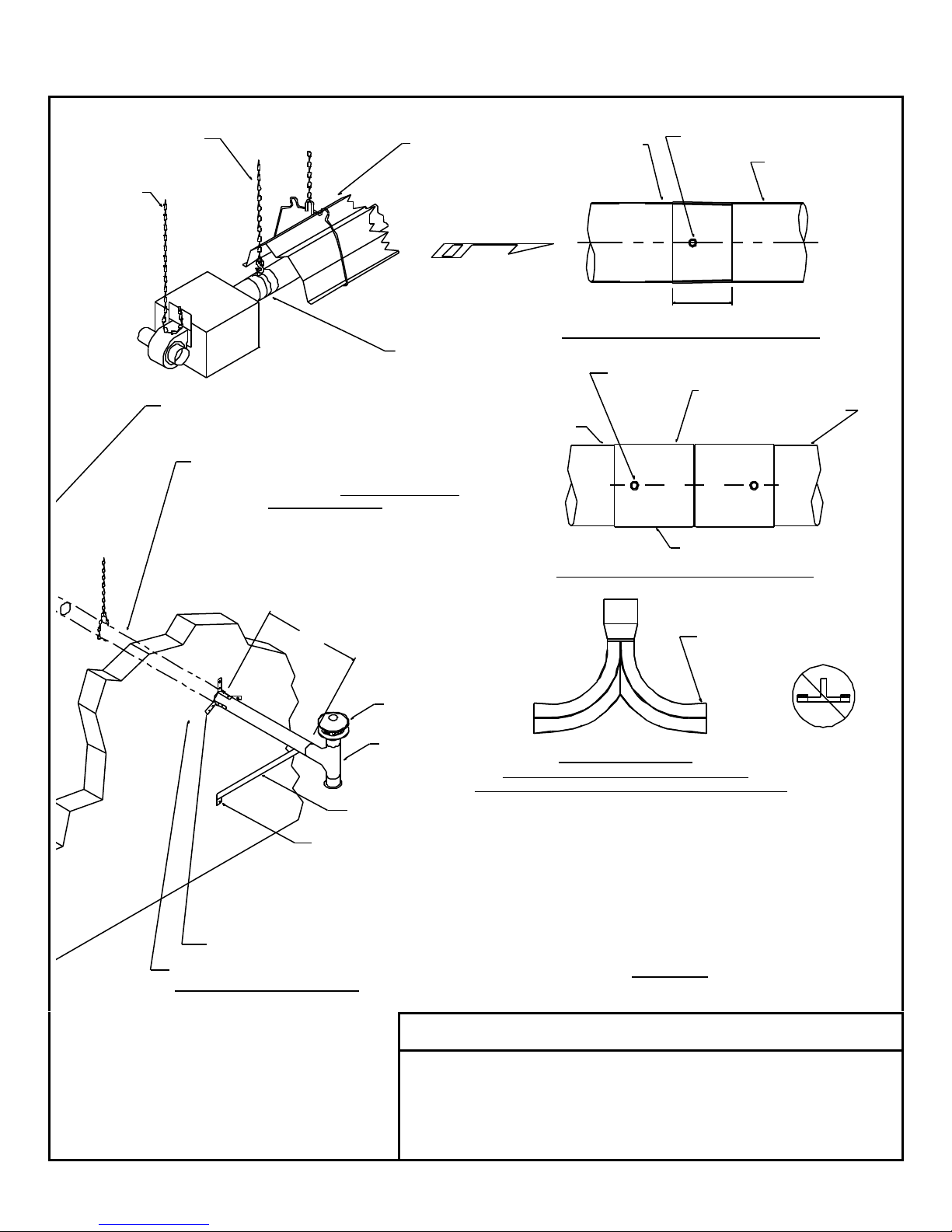
INSTALLATION (2 OF 2)
• The next heat exchanger tube, with it’s weld seam up, [for 15 ft. and 20 ft. (4.6 and 6.1 m) systems only] can
be put into the respective suspended hanger bracket assemblies.
• Manually push the flared end of the heat exchanger tube [it has two (2) holes in it] over the swaged end of the
combustion chamber as far as you can.
• [NOTE: The swaged end of the combustion chamber has a colored line 3 in. (7.6 cm) from the end].
COLOR INSERTION INDICATOR
STEP
6
STEP
7
SWAGED END
AIR FLOW
• Go to the swaged end of the heat exchanger tube, and with a 2 pound (0.9kg) hammer and a two (2) in. by
four (4) in. (5 cm x 10 cm) block of wood, hit the end of the tube until you have 3 in. (7.6cm) of insertion (the
colored line will still be visible).
• Ensure all tubes are straight and level with the weld seam at the top before installing the screws. See
the TUBE ASSEMBLY TIPS Section for more information.
• Tek screw the tube joint connection through the two holes provided in the flared end with (2) two #12 MULTI-
METAL Tek screws (supplied with the tube).
• Place a reflector over the heat exchanger and into the suspended hanger bracket assemblies.
WELD SEAM MUST BE ON TOP
FLARED END COMES UP TO, BUT DOES NOT
COVER COLOR INSERTION INDICATOR
• Slip the burner’s tube into the burner coupler previously installed in Step 4.
• Once the burner is level, straight and inserted against the center stop, use (2) two #12 MULTI-METAL Tek
screws (supplied with the coupling) to fasten the burner to the coupling.
• Insert the “S” hook of the burner safety chain into the center hole of the burner safety chain bracket and then
crimp the hook closed.
SAFETY CHAIN
[6" (15 CM) OF
SLACK NEEDED]
PILOT HOLE
FLARED END
#12 MULTI-METAL SELF
DRILLING SCREWS (2 EA.)
SUSPENSION
BRACKET
BURNER
COUPLER
STEP
8
• The # 12 MULTI-METAL Tek screws supplied with the coupling
• Make sure all chains are plumb and vertical to prevent damage
• Reflectors must not be angle mounted more than 30° from
horizontal for 65 to 125 MBTUH (19 – 37 kW) or 45° from
horizontal for 40 to 60 or 130 to 200 MBTUH (12 – 18 or 38 – 59
kW).
• If located near a door or windy area, fasten reflectors to
tube/reflector hangers with sheet metal screws or other
positive means. See WINDY CONDITION NOTES.
WARNING IMPORTANT
MUST NOT be substituted with any other type of Tek screw. If
you loose them, contact the factory for new ones.
CAUTION
to tubes.
#12 MULTI-METAL SELF
DRILLING SCREWS (4 EA.)BURNER
• Connect the gas supply as instructed in the GAS
SUPPLY AND GAS PRESSURE section.
• Connect the electrical supply as instructed in the
ELECTRICAL SUPPLY AND THERMOSTATIC
CONTROL section.

GQ pg. 22
ELECTRICAL SUPPLY AND THERMOSTATIC CONTROL (1 OF 2)
ELECTRICAL SUPPLY 120 VAC THERMOSTATIC CONTROL
DUAL SYSTEM ONLY
TO
BURNER
RECEPTACLE
(BY OTHERS)
TO
BURNER
TRANSFORMER/RELAY
(MOUNTED TO 4X4
JUNCTION BOX
PROVIDED BY OTHERS)
RED
HOT
BROWN
• Voltage: 120VAC- 1 phase- 60 Hz.
• Maximum Amps: 3.0 (1.33 actual full load amps).
• Flame safety: Electronic.
• Ignition: Direct Spark.
• Wiring must conform to the latest edition of the
National Electric Code (ANSI/NFPA 70) or local
code legally authorized.
• Electrical power takeoff must be connected to a
separately fused circuit with a disconnect, and
must be properly polarized and grounded to the
heaters power cord.
• Do not run wiring over the heaters or in direct
view of radiant heat.
• If any of the wiring supplied must be replaced
use type 16 AWG (1.0mm2), or equivalent with
2/64” (.08 cm) insulation and a minimum
insulation temperature of 302°F (150°C).
CAUTION – 24VAC THERMOSTAT
DO NOT try to connect more than three burners to a
24 VAC thermostat. The transformer relay is rated to
operate only three heaters safely. Failure to do so
may cause serious bodily harm or property damage.
SEQUENCE OF OPERATION
GREEN (GROUND)
WHITE (NEUTRAL)
120-1-60
BLACK
(LINE)
DISCONNECT
24 VAC THERMOSTAT AND TRANSFORMER
FUSED DISCONNECT
(BY OTHERS)
(HOT)
BLACK
(NEUTRAL)
WHITE
(GROUND)
GREEN
120-1-60 (3 WIRE SERVICE)
FUSED
THERMOSTAT
WIRING BY
PURCHASER
WIRE NUT
(BY OTHERS)
BLACK
BLACK
WHITE
• Thermostat calls for heat.
• 120 VAC is applied to the blower and validation
light PL-1 indicates power is ON.
• Air flow switch closes contacts after it senses an
increase in air pressure due to fan reaching
operational speed.
• Validation light PL-2 indicates combustion air
supply and exhaust venting back pressure is
normal.
• Ignition Detection Control (IDC) is turned on and
begins a pre-purge time period.
• A spark is developed at the igniter and the gas
valve is opened to the first step of its two step
operation.
• Burner ignites and 5 seconds later the gas valve
steps up to its operating position. DC electrical
current flows from sensing electrode through
flame to ground.
• IDC senses flame presence, turns OFF spark,
gas continues flowing through valve.
• Validation light PL-3 indicates normal burner
operation.
• During first trial-for-ignition period or upon any
flame outage at sensing electrode, the IDC
responds and begins sparking within 0.8
seconds. A 15-second trial-for-ignition period
begins to re-light the burner. If flame is reestablished, normal operation resumes. If the
burner does not light after first try, the interpurge sequence is completed between trials to
re-light the burner. If the burner fails to light
(10DX-117) or after third trial (35-725), IDC will
de-energize the valve and go into lockout mode.
• For lockout recovery, reset thermostat below
ambient temperature or disconnect electrical
power supply for five (5) seconds.
24 VOLT
THERMOSTAT
NEUTRAL
WIRE NUT SYMBOL
WIRING BY OTHERS
GROUND
GREEN GROUND
SCREW IN 4X4
JUNCTION BOX
POWER CORD
FROM BURNER
BURNER WIRING SCHEMATIC/INTERCONNECTION DIAGRAM
If any of the original wire as supplied with the appliance must be replaced, it must be replaced with wiring
material having a temperature rating of at least 302°F (150°C) and shall have a minimum size of 16 AWG.
BLACK
N
GAS VALVE
115V.-1PH.-60HZ.
(+)
WHITE
BLACK
BLACK
SENSOR
GROUND
SPARK
(-)
(HOT)
(NEUTRAL)
WHITE
BLACK
BLACK
BLACK
IDC
(35-725)
RED
RED
AIR FLOW SWITCH
- WIRE NUT SYMBOL
PL-1
N
BLACK
BLACK
GREEN
RED
WHITE
BLACK
WHITE
HIGH VOLTAGE LEAD WIRE
YELLOW
GREEN
GROUND
SCREW
PL-2
N
FAN MOTOR
PL-3
BLACK
BLACK WHITE
YELLOW
GREEN
WHITE
(GROUND)
GREEN

GQ pg. 23
ELECTRICAL SUPPLY AND THERMOSTATIC CONTROL (2 OF 2)
SEQUENCE OF OPERATION (CONT’D) BURNER WIRING LADDER DIAGRAM
• If the flame does fail during ignition or
normal operation, it is detected by the
flame sensor rod, and the IDC then closes
the gas valve locking out the system until
the thermostat is cycled to the OFF
position.
• W hen the thermostat is satisfied, the whole
system is de-energized until another call for
heat.
• When installing or servicing this heater,
wait at least 5 minutes between attempts
for ignition.
GENERAL INSTALLATION NOTES
• Locate the thermostat as specified in the
heating plan.
• If it is not in the heating plan, follow the
instructions provided with the thermostat.
• If instructions are not provided with the
thermostat, locate it four to five feet above
the floor where it will not be directly
affected by the heat from the heater,
outside drafts, or the sun.
• A location that best represents the average
temperature of the room is the most
desirable.
• If two heaters are installed on a common
exhaust vent they must be controlled by the
same thermostat.
MAXIMUM NUMBER OF HEATERS FOR
OPTIONAL THERMOSTATS
If any of the original wire as supplied with the appliance must be replaced, it must be replaced with wiring
material having a temperature rating of at least 302°F (150°C) and shall have a minimum size of 16 AWG.
BLACK
BLACK
BLACK
AF-1
RED
AIR FLOW SWITCH
IDC
35-725
RED
GREEN
RED
WHITE
BLACK
WHITE
YELLOW
120V.-1PH.-60HZ.
(+)
(-)
(GROUND)
(HOT) (NEUTRAL)
FAN MOTOR
BLACK
BLACK
BLACK
HI-VOLTAGE WIRE
CHASSIS GROUND
PL-1
PL-2
PL-3
GAS VALVE
GREEN
WHITE
BLACK
WHITE
BLACK
BLACK
WHITE
POWER ON
FAN
MOTOR
AIR
PRESSURE
NORMAL
BURNER
OPERATION
NORMAL
GAS VALVE
SENSOR
GROUND
SPARK
HEATERS IN SERIES WITH A 120 VAC THERMOSTAT
NOTE: SEE TABLE FOR MAXIMUM NUMBER OF
HEATERS ON A THERMOSTAT
BURNER 1 BURNER 2 BURNER 6 BURNER 7
Number
of
Heaters
Part No.
Volts
AC
Amps
132026-4 120 22.0 7
132486 120 16.0 5
0002-42-157 120 16.0 5
132700 24 .15-1.0 3*
0002-42-122 24 2.5 3*
0002-42-121 24 1.5 3*
* When installing a Low-Intensity heater to any
thermostat, the installer should allow for 3 amps
per heater as the blower tends to use more
electricity than its rating during its start-up
period. This is why all of the 24 VAC
thermostats must be connected to a 120 VAC
transformer relay, which will safely support only
three heaters.
FUSED
T'STAT
120V.
1PH.
HOT
NEUTRAL
GROUND
HEATERS IN SERIES WITH A 24 VAC THERMOSTAT
NOTE: BROWN WIRE IS NOT USED BUT MAY BE ELECTRICALLY HOT.
PROTECT PERSONNEL AND THE CIRCUIT BY SCREWING ON A WIRE NUT
BLACK
WHITE
GREEN
FUSED
DISCONNECT
(BY OTHERS)
WIRING BY
OTHERS
WIRE NUT
BY OTHERS
BLACK
BLACK
WHITE
NEUTRAL
GROUND
TRANSFORMER/RELAY
RED
BROWN
LO-VOLT
T-STAT
GREEN GROUND SCREW
IN 4X4 JUNCTION BOX
HOT
BLACK
BURNER 1 BURNER 3
BLACK
CAUTION: NO MORE THAN THREE
HEATERS IN A SERIES

GQ pg. 24
GAS SUPPLY AND GAS PRESSURE
GAS SUPPLY PIPING INLET GAS PRESSURE
• Piping must be installed in accordance with local codes and/or
ANSI Z223.1-latest edition (NFPA 54-latest edition), National
Fuel Gas Code.
• Piping must have drip leg and a ground joint union.
• All pipe connections must have pipe joint compound, resistant to
LP/propane gas action.
• Isolate regulators, flexible gas connectors, and heaters during
high-pressure leak testing.
• All gas lines must be purged before startup.
• Use only agency approved flexible gas connector with shut-off
cock for connecting to heater. (SEE CAUTION)
• Use swing or swivel joint in addition to rigid piping if local codes
prohibit use of a flexible gas connector.
• Local codes may require additional shut-off cock ahead of the
drip leg.
CAUTION: “LAZY LOOP”
• Stress from expansion and contraction of heater may cause
excessive wear on the gas connection.
• If local codes permit, flexible gas connectors must be in a “Lazy
Loop”, arrangement as shown on drawing below.
• It is important to maintain dimensions on drawing below.
Heater length Expansion Heater length Expansion HIGH INLET GAS PRESSURE
10-20 ft
(3.1-6.1 m)
25-30 ft
(7.6-9.1 m)
35-40 ft
(10.7-12.2 m)
1.1 in
(2.8 cm)
1.5 in
(3.8 cm)
1.8 in
(4.6 cm)
45-50 ft
(13.7-15.2 m)
55-60 ft
(16.8-18.3 m)
65-70 ft
(19.9-21.3)
2.1 in
(5.3 cm)
2.4 in
(6.1 cm)
2.7 in
(6.7 cm)
GAS PRESSURE MEASUREMENTS MANIFOLD OUTLET GAS PRESSURE
• Use only water or red oil manometer
to make measurements – NOT A
DIAL GAUGE.
• Make ALL measurements and
adjustments when this heater and
ALL other gas burning equipment
connected to the same gas meter are
operating at maximum capacity.
• Fluctuations in inlet pressure can alter manifold pressure.
• For manifold pressure adjustment locations, refer to drawing below.
• Remove pipe plug from Test Point ‘B’; insert a barb fitting connected to the manometer.
• For all heaters remove the slotted cap screw.
• Turn adjustment screw clockwise to increase pressure or counterclockwise to decrease
pressure. Screw may require a flat head screwdriver or a 3/32” (2.38mm) hex key.
RATING: MBTUH (kW) MANIFOLD PRESSURE
40 to 100 (12 to 29) 3.5 in. WC (8.9 cm WC) (Nat./LP)
105 to 200 (31 to 59) 5.0 in. WC (12.7 cm WC) (Nat./LP)
• Inlet gas pressure must be measured on the inlet side of the
valve at Test Point ‘A’ in the supply piping and must conform to
the following:
RATING
GAS TYPE
MBTUH
(kW)
MINIMUM:
NATURAL GAS
NATURAL GAS
40 to 125
(12 to 37)
130 to 200
(38 to 59)
LP/PROPANE GAS ALL
MAXIMUM:
NATURAL GAS
LP/PROPANE GAS
ALL
IMPORTANT
• Gas pressure at Test Point ‘A’ cannot be more than 14 inches of
water column (in. WC) (½PSI) (35 cm WC), confirmed by actual
field test. (Heater on or off)
• For pressure greater than 14 in. WC (35 cm WC) a positive
lockout type high-pressure regulator must be installed in the gas
line ahead of the burner.
• Always check local codes for gas venting requirements for high-
pressure regulators.
• Over-protection pressure devices (OPD’s) may be required in
certain jurisdictions.
• High inlet gas pressure regulators will NOT turn off the flow of
gas.
PRESSURE
In. WC
(cm WC)
6
(15)
7
(18)
11
(28)
14
(35)
WHEN GAS PRESSURE
EXCEEDS 14" W.C.
(35 CM W.C.)
A FIRST STAGE
REGULATOR
MUST BE
INSTALLED.
RECOMMEND GAS CONNECTION ARRANGEMENT USING A FLEXIBLE GAS CONNECTOR.
5"
(13CM)
15"
(38 CM)
(17 CM)
6-1/2"
GAS COCK
(SUPPLIED BY OTHERS)
1/2" (1.27 CM)
O.D. FLEXIBLE
GAS CONNECTOR
24" (61 CM) LONG
STAINLESS STEEL
Excessive torque on the burner gas inlet manifold pipe may cause damage to burner. Always use two (2) wrenches when making pipe
connections. Important: Check for leaks with soap solution. DO NOT USE FLAMES! Leak test solution may cause corrosion. After test,
water rinse to clear out any remaining solution.
LOCAL CODES MAY REQUIRE
AN ADDITIONAL SHUT-OFF COCK
BE INSTALLED IN THE GAS LINE
AHEAD OF THE DRIP LEG
DRIP LEG
TEST POINT 'A'
(INLET)
CAUTION
MANIFOLD
PRESSURE
ADJUSTMENT
(ROBERT SHAW
VALVE)
TEST POINT 'B'
(OUTLET)
SAFETY
CHAIN
MANIFOLD
PRESSURE
ADJUSTMENT
(WHITE RODGERS
VALVE)

STARTUP
STARTUP IMPORTANT
GQ pg. 25
• Remove the burner cover by removing the 4 sheet
metal screws from the topside of the burner cover.
• Remove the 1/8 NPT pipe plug from Test Point B and
connect manometer. Refer to the drawing in the GAS
SUPPLY AND GAS PRESSURE section.
• Depress the dial on the gas valve, and make sure the
gas valve is in the ON position.
• Turn on the electrical and gas supply and set the
thermostat above the ambient room temperature, to call
for heat.
• Refer to the ELECTRICAL SUPPLY AND
THERMOSTATIC CONTROL section for proper
sequence of operation.
• If the heater does not operate normally, refer to the
BURNER TROUBLESHOOTING section to diagnose
and correct the situation.
• Turn gas and electrical supply off, remove the
manometer and replace the 1/8 NPT pipe plug into Test
Point B on the gas valve.
• Check again for gas leaks. Refer to GAS SUPPLY
AND GAS PRESSURE section as needed.
• Cycle the heater several times by means of the
thermostat, allowing at least five minutes between
cycles. If the heater operates normally, replace the
burner cover and screws.
• If the heater is vented directly outdoors, observe and
verify the flue gases exiting from the exhaust vent are
not impinging on building construction.
• Check and, if necessary, adjust the manifold pressure!
.156 IN. (3.96 CM)
SPARK GAP
± 1/32 IN. (.08 CM)
.208'' (.53 CM)
GROUND GAP
REF.
SAFETY CHAIN BRACKET
BLOWER
INLET
AIR
COLLAR
AIR ORIFICE
(3) THREE NEON
VALIDATION LIGHTS
(3) THREE PRIN G PLUG
WITH 36 IN. (91CM)
LENGTH CORD
TUBING ADAPTOR
BURNER CORE ASS'Y
MAIN ORIFICE
VINYL TUBING
IGNITION DETECTION
CONTROL
IGNITION LEAD WIRE
AIR FLOW SWITCH
AIR FLOW SWITCH TUBING CONNECTIONS
THE SWITCH "+" OR "HIGH" SIDE TUBE GOES TOWARD THE BLOWER SIDE.
THE SWITCH "-" OR "LOW" SIDE TUBE GOES TOWARD THE IGNITOR SIDE.
BURNER NOZZLE
IGNITOR BRACKET
SHEET METAL SCREW
OBSERVATION PORT
1/2" NPT GAS INLET
GAS VALVE

GQ pg. 26
MAINTENANCE
• FOR SAFETY REASONS, BEFORE PERFORMING ANY MAINTENANCE, DISCONNECT AND
LOCKOUT THE ELECTRICAL SUPPLY, INCLUDING THE THERMOSTAT, BY POSITIVE MEANS.
• All maintenance and/or repair MUST be performed by someone trained and qualified to work on gas and electrical
equipment.
• Annual maintenance done prior to the beginning of each heating season is all that is usually necessary.
• In dirty, dusty, or wet atmospheres, it may be necessary to examine and perform needed maintenance at additional
times during the middle of the heating season. Experience will dictate the frequency.
• Radiant tubes, combustion air ducting, and exhaust venting should be inspected to make sure that: suspension points
are secure, tube clamp nuts are tight, heater is level, chains are plumb and taut (except for burner safety chain), vent
pipe joints are properly sealed, “S” hooks are crimped closed, there is no excessive exterior buildup of dust or dirt, and
make sure there are no restrictions such as bird or insect nests in the combustion air or vent piping or their
terminations.
• Reflectors should be inspected to make sure they are clean and secure, as detailed in the INSTALLATION section. If
dirty, reflectors should be removed and washed with isopropyl alcohol, Simple Green, or buffed with mild rubbing
compound.
• On U-tube systems, the U-bend reflector support nuts should be inspected to make sure they are tight.
• Inspect the inside of the blower housing for excessive dust or dirt buildup on the impeller wheel and make sure the air
orifice and the inlet air collar are properly attached. Check that the blower can come up to full speed.
• Remove the cover by removing the 4 sheet metal screws on top of the cover.
• Remove the ignitor by removing ONLY the end where the vinyl tubing is attached to the ignitor bracket; the fitting to
which the vinyl tubing was connected; the ignition lead wire from the ignition detection control; and the sheet metal
screw holding the ignitor bracket to the burner housing wall.
• Remove the ignitor carefully; its’ electrodes make a ninety degree turn to the right.
• Clean the ignitor’s porcelain insulation and check for cracks and proper gaps (see STARTUP section).
• Within the interior of the burner tube, examine the burner nozzle, primary air holes, main orifice and surrounding area
for build up of dust or dirt. Clean if necessary.
• Reinstall the ignitor by following the previous instructions in reverse order.
• Examine the ignition detection control for overheating (warped plastic housing, discoloration, etc.)
• A visual inspection of gas valve, airflow switch, and wiring is adequate.
• Inside each clear vinyl tube used for air flow sensing is a small snubber (aluminum cylinder piece). Visually inspect for
cleanliness.
• Clean any surfaces needed and correct any situations found in disrepair.
• Replace the cover and sheet metal screws.
• The blower motor is of the permanently lubricated type and requires no additional lubrication.
• Double check that the area under the heater is kept clear and free from combustible materials, gasoline, and other
flammable vapors and liquids.
• Reconnect electrical supply and cycle the heater several times using the thermostat allowing (5) five minutes between
cycles for proper operation.
• WARNING: Do not operate heater with any part bypassed, with any part failed or in any possible
situation that may compromise safety. Personal injury, death, and/or property damage could result.

GQ pg. 27
TROUBLESHOOTING
Check for symptoms and possible causes in the order presented from the top of this chart to the bottom.
The symptoms and possible causes are in a logical progressive order as in a flow chart.
SYMPTOM POSSIBLE CAUSE CORRECTIVE ACTION
New Installation.
Gas Odor. 1. Gas pipe joints loose. 1. Check joints with soap solution, tighten as
Blower / PL-1 light does
not come on when
system energized.
Pressure switch does
not close / PL-2 light
does not come on.
Ignitor does not spark /
PL-3 light does not
come on.
Burner does not ignite.
(There are three trialsfor-ignition before the
IDC goes into lockout).
Spark does not stop
when the burner ignites.
Burner does not stay lit
until the thermostat is
satisfied.
Heater will not turn off. 1. Thermostat defective. 1. Replace thermostat.
1. Heaters not isolated during high pressure leak
testing.
2. All gas lines not completely bled of air. 2. Disconnect flex hose at each heater until gas is
3. Gas supply regulator reversed. 3. Remove and install properly.
1. Power supply fuse defective. 1. Replace fuse.
2. 115 VAC not reaching heater. 2. Check thermostat and wiring and fix.
3. Blower defective. 3. Replace blower.
1. Inlet or exhaust piping not the proper size and
length. (Refer to manual.)
2. Inlet or exhaust termination fittings not to factory
specifications.
3. Inlet or exhaust blocked. 3. Clear blockage.
4. Airflow tubing or snubber orifice blocked in one
or both tubes.
5. Blower wheel dirty or damaged. 5. Clean or repair wheel.
6. Airflow pressure switch defective. 6. Replace airflow pressure switch.
1. 115 VAC not reaching the Ignition Detection
Control (IDC) due to loose wire or connector.
2. High-voltage wire loose or damaged. 2. Secure high-voltage wire or replace ignitor.
3. Ignition Detection Control (IDC) defective. 3. Replace IDC box.
1. Gas supply not turned on. 1. Open all manual gas supply valves.
2. Ignitor not sparking at the tips. 2. Measure spark gap and adjust gap as
3. Ignitor not sparking at correct gap. 3. Replace ignitor.
4. Gas inlet pressure not correct. (See serial
plate). Gas inlet piping not sized correctly.
5. Gas inlet pressure not correct. (See serial
plate). Gas supply regulator not set correctly.
6. Gas supply regulator sticking. 6. Replace gas supply regulator.
7. Combination gas valve not in the ON position. 7. Turn combination gas valve to the ON position.
8. Ignition Detection Control (IDC) not sending
115VAC to combination gas valve.
9. Combination gas valve defective. 9. Replace combination gas valve.
10. Combination gas valve outlet (manifold)
pressure not correct. (See serial plate).
11. Main or sub gas orifice blocked by spider web,
etc.
12. Gas orifice(s) or air orifice not correct size. 12. Install correct size gas orifice(s) or air orifice.
1. Power supply not grounded to a true earth
ground.
2. Flame sensor wire loose or damaged. 2. Secure flame sensor wire or replace wire
3. Flame signal not at least -17 VDC. 3. Check gas inlet and manifold pressures
4. Ignition Detection Control (IDC) is defective. 4. Replace IDC box.
1. Flame sensor wire is loose or damaged. 1. Replace wire harness to IDC box.
2. Inlet or exhaust partially blocked. 2. Clear blockage.
3. Airflow pressure switch erratic or defective. 3. Consult factory or replace airflow pressure
4. Flame signal not at least -17 VDC. 4. Check gas inlet and manifold pressures
5. Ignition Detection Control (IDC) defective. 5. Replace IDC box.
1. Replace combination gas valves on each
heater.
present. Connect flex hose and leak test.
needed.
1. Replace piping as required.
2. Replace fittings as required.
4. Clear blockage.
1. Repair loose wire or connector.
necessary to 5/32" [0.156" (3.96mm)].
4. Replace inlet gas piping with correct size pipe.
5. Adjust gas supply regulator to set inlet pressure
to proper level. (See serial plate).
8. Replace IDC box.
10. Adjust combination gas valve regulator to set
inlet (manifold) pressure to proper level.
11. Clear blockage.
1. Install a true earth ground to the power supply.
harness to IDC box.
compared to the possible causes in the previous
symptom where the burner does not ignite.
switch.
compared to the possible causes in the previous
symptom where the burner does not ignite.

GQ pg. 28
Any substitutions of factory-installed parts without prior written permission may
result in unsafe operation, property damage, personal injury, death, voids CSA
design certification, and manufacturer’s warranty.
REPLACEMENT PARTS
! WARNING !
10
8
9
7
6
4
1
1. Gas valve 12. Safety chain bracket with nuts
5
22
3
2
19
20
21
17
18
15
16
11
12
13
14
2. Gas manifold assembly with fittings 13. Blower motor
3. Air flow switch (combustion) tubing assembly with
snubber and fittings
4. Burner core 15. Power cord strain relief bushing
5. Ignitor gasket 16. System validation light
6. Ignitor 17. Ignition detection control
7. Air flow switch (exhaust) tubing assembly with snubber
and fittings
8. Air flow switch 19. Wire harness assembly
9. Burner cover 20. Gas manifold fitting (at valve)
10. Inlet combustion air collar 21. Gas sub orifice
11. Air orifice plate 22. Gas main orifice (located inside of burner tube)
14. 36” (91cm) long power cord with 3-prong grounded plug
18. Burner tube holding bracket with screws
Due to continuous product improvement, please provide serial and model number prior to
ordering replacement parts to assure safe repairs and maintenance.

THIS PAGE INTENTIONALLY LEFT BLANK
GQ pg. 29

FOR SERVICE OR REPAIR, FOLLOW THESE STEPS IN ORDER:
FIRST: Contact the Installer
Name __________________________________________________
Address ________________________________________________
________________________________________________________
________________________________________________________
Phone __________________________________________________
SECOND: Contact the Nearest Distributor
Model No.: ______________________________________________
Unit Serial No.: ___________________________________________
Date of Installation: ________________________________________
P.O. Box 80217, Rochester MI 48308-0217
Toll Free: 1-866-664-3824
FAX: (248) 651-0357
E-mail: sales@sunspanheaters.com
Website: www.sunspanheaters.com
 Loading...