

SunSpan SRHS-40-20AN, SRHS-40-15AN, SRHS-40-20AL, SRHS-45-20AN, SRHS-45-20AL Installation, Operation & Maintanance Manual
...
Form SRH-IOM-1
500011
Residential Garage Heater
Installation, Operation, & Maintenance
Instruction Manual
(Mount a copy of these instructions adjacent to the heater)
MODEL IDENTIFICATION
Record the information from the product identification label here for future reference.
Heater Model No.: _________________________ Heater Serial No.: ________________________
Rating: __________ BTUH Type of Gas: Nat ___ LP/Propane ___ Date Installed ____________
FOR YOUR SAFETY
IF YOU SMELL GAS:
1. Extinguish any open FLAME.
2. Do NOT try to light any appliance.
3. OPEN windows.
4. Do NOT touch electrical switches; do
NOT use any telephone in the house.
FOR YOUR SAFETY
Do not store or use GASOLINE or other FLAMMABLE VAPORS or LIQUIDS in the vicinity of
this or any other appliance.
This unit is not to be installed in indoor living/sleeping areas.
5. CALL your gas supplier immediately
from a NEIGHTBOR’S home. Follow the
gas supplier’s instructions.
6. IF you can’t reach your gas supplier,
CALL the FIRE DEPARTMENT.
!! WARNING !!
THESE INSTRUCTIONS must be carefully read and completely understood BEFORE
attempting to install , operate, or perform maintenance service on this GAS-FIRED
APPLIANCE. Installation and Service MUST be performed by a QUALIFIED service agency,
installer, contractor, or gas supplier. Failure to comply with the manufacturer’s instructions can
result in unsafe operation, property damage, personal injury, and/or death. A gas-fired
appliance can expose you to substances in fuel or from fuel combustion which have been
determined by the State of California to cause cancer, birth defects, or other reproductive
harm. Contact factory for further information. Keep these instructions for future reference.
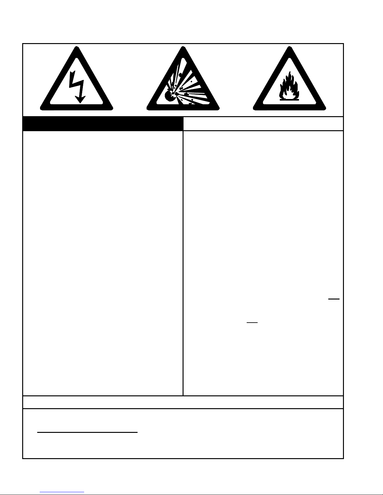
EXPLANATION OF HAZARD INTENSITY LEVELS
DANGER: Failure to comply WILL result in severe personal injury, death, and/or property damage.
WARNING: Failure to comply could result in severe personal injury, death, and/or property damage.
CAUTION: Failure to comply could result in minor personal injury, and/or property damage.
This manual is to be left with the owner after installation of this unit.
OWNER: Store this manual in a safe place to furnish your serviceman with the necessary
information for servicing.
QUESTIONS? Call the SunSpan factory at 1-866-664-3824.
Monday – Friday 8 a.m. to 5 p.m. Eastern Time
Copyright © 2005, SunSpan
SRH pg. 2
•
•
•
•
•
•
•
•
•
•
•
•
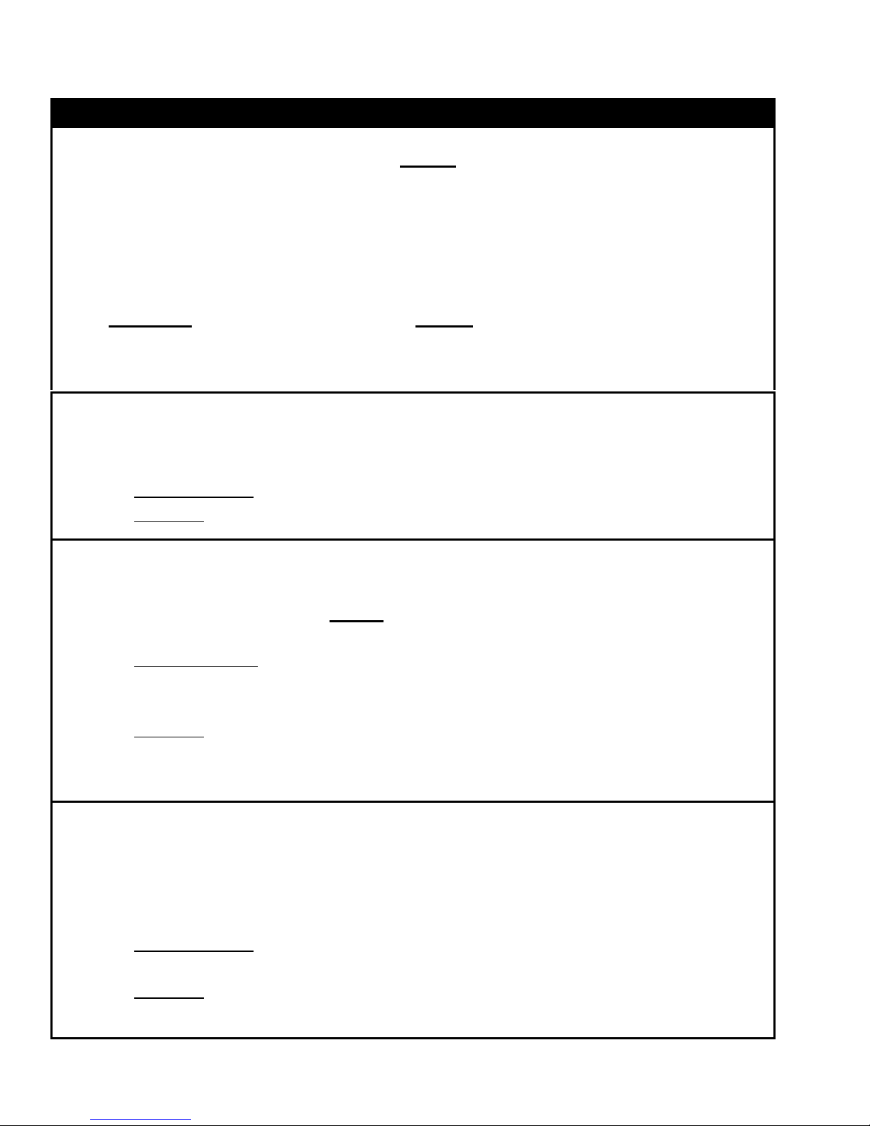
WARNINGS
WARNING CAUTION
FIRE OR EXPLOSION HAZARD
Can cause property damage, severe injury or
death.
Read manual carefully before installing, or
servicing this equipment, or serious injury or
death may result.
Check minimum clearance to combustibles to
make certain that heater is in a safe location.
Combustible items located too close to the
heater could cause a serious fire hazard. In
storage areas, signs for maximum permissible
stacking height to maintain clearance from the
heater to combustible materials must be
posted adjacent to the heater thermostats or in
the absence of such thermostats in a
conspicuous location.
Operating the heater in an atmosphere
containing combustible dust or flammable
vapors is dangerous and may potentially result
in injury or death.
Heaters must be oriented in such a way as to
maintain minimum clearances to vehicles
parked underneath them.
This heater expands and contracts with each
cycle. The installation of the gas connection
and mounting hardware must accommodate
this movement; otherwise, a fire or explosion
hazard may occur.
This heater is equipped with an automatic
ignition and does not contain a pilot. DO NOT
attempt to light the burner manually, this could
result in serious personal injury or fire hazard.
MECHANICAL HAZARD
• DO NOT use high pressure to test the gas
pipes with the burner still attached. This will
cause damage to the controls within the
burner requiring them to be replaced.
If heater is being operated in an atmosphere
with a negative pressure or an atmosphere
containing contaminants, an outside
combustion air supply is required. Failure to
provide outside combustion air may allow
excessive heat to back up to the blower wheel
and bearings severely shortening service life.
• Correct inlet pressure is important to efficiency
and long lasting operation of the burner.
The burner, tubing, and accessories expand
and contract with each cycle. The system
must be installed so that the mounting
hardware and gas line will accommodate
these changes.
All models of low-intensity heaters include a
turbulator, which must be located in the last
ten (10) feet (3.0 m) of the burner tube
[exception: 15-foot (4.6 m) units have the
turbulator in the first 10 feet (3.0 m).]
Before servicing the burner or removing the
cover panel, all electrical and gas supplies
must be disconnected.
Give consideration to construction such as
partitions, storage racks, hoists, etc., and their
relation to the installation of the heater.
The heater must be installed and serviced
ONLY by trained gas installation and service
personnel.
Failure to follow these instructions may result in injury or property damage.
RH Residential Heaters shall not be used in the following environments:
• Indoor living/sleeping quarters
• Enclosed swimming pools
• Outdoors
NOTE: Contact factory if in any doubt.
IMPORTANT
• Explosion-proof environments
• Process heating
• Contaminated atmosphere applications.
SRH pg. 3
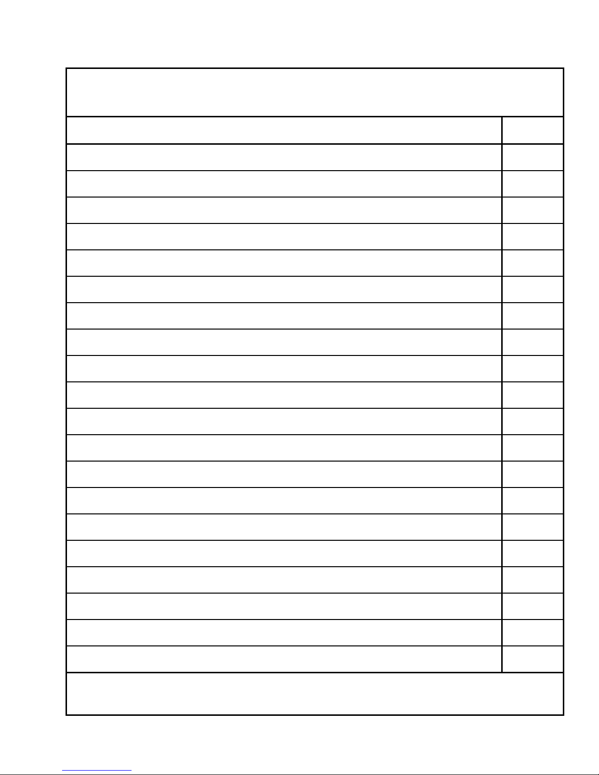
TABLE OF CONTENTS
This instruction manual may not cover all details or variations in this equipment, or cover every
possible situation to be met in connection with installation, operation, or maintenance. Should
problems arise that are not covered sufficiently in these instructions, the purchaser is advised to
contact the engineering department for further information.
SECTION TITLES – summary of information included PAGE(S)
WARNINGS – precautions and important safety information
TABLE OF CONTENTS
INSTALLATION CODES – applicable codes and warnings
CLEARANCE TO COMBUSTIBLES – minimum distances from heater to combustible objects
MOUNTING CONSIDERATIONS – minimum heater mounting heights, high altitude considerations
OVERVIEW DRAWINGS – overview of venting, suspension, location, and typical installation
BASIC SYSTEM CONFIGURATIONS – straight and U-tube configurations with component identification
COMBUSTION CHAMBERS/HEAT EXCHANGERS – components and specifications
COMBUSTION AIR SUPPLY – application, construction, dimensions, and illustrations
EXHAUST VENTING – application, construction, dimensions, and illustrations
U-TUBE INSTALLATION – suspension and orientation of U-tube heaters
2
3
4-5
6
7
8-9
10
11
12
13
14
U-BEND REFLECTOR INSTALLATION – exploded view and instructions
TUBE ASSEMBLY TIPS – helpful tips to assemble tubes
INSTALLATION – preparation and installation
ELECTRICAL SUPPLY AND THERMOSTATIC CONTROL – electrical ratings, schematics, 24 and 120 VAC
thermostat arrangements, illustrations
GAS SUPPLY AND GAS PRESSURE – gas piping, inlet and manifold pressures
STARTUP – procedures
BURNER TROUBLESHOOTING – flowchart
MAINTENANCE – basic procedures
REPLACEMENT PARTS – exploded view and part descriptions
All rights reserved. No part of this work covered by the copyrights herein may be reproduced or copied by any means:
graphic, electronic or mechanical, including photocopying, recording, taping, information storage and retrieval systems
without written permission.
15
16-17
18-19
20-21
22
23
24-25
26
27
SRH pg. 4
Initial adjustment and light-off MUST be performed by qualified,
trained, and experienced personnel familiar with combustion systems,
electrical and gas control/safety circuitry, and overall installation.
Instructions provided by the company or individual responsible for the
complete installation of the entire system take precedence over those
provided by this instruction manual. If these instructions conflict with
local codes or regulations, contact the factory at the on the cover
BEFORE start-up. The installer MUST be familiar with all of the
various requirements and is responsible for compliance with
applicable codes.
AGENCY DESIGN CERTIFICATION:
CSA International (formerly A.G.A. and CGA).
• United States: A.G.A. Requirement No. 7-89
INSTALLATION CODES (1 OF 2)
!! WARNING: READ THIS FIRST !!
• Canada: CSA 2.32a-M99
GENERAL INSTALLATION & GAS CODES:
Heater must be installed ONLY for use with type of gas appearing on
its rating plate.
• United States: In the absence of local codes, installation must
comply with the National Fuel Gas Code ANSI Z223.1 (NFPA-54) -
latest edition.
• Canada: In the absence of local codes, installation must comply
with CAN/CGA B149.1 and B149.2 Installation Codes in Canadalatest edition.
GAS SUPPLY LINES:
A 1/8 inch NPT plugged tap must be installed in the gas line
connection immediately upstream of the burner farthest from the gas
supply meter to check and confirm the system’s gas pressure.
• United States: Installation must comply with the National Fuel Gas
Code ANSI Z223.1 (NFPA-54)-latest edition.
• Canada: Installation must comply with CAN/CGA B149.1 AND
B149.2 Installation Codes in Canada-latest edition.
SRH pg. 5
INSTALLATION CODES (2 OF 2)
!! WARNING: READ THIS FIRST !!
MANUAL GAS SHUT-OFF (CANADA ONLY):
A manual shut-off valve shall be of the plug, ball, or eccentric type
and it shall not be subjected to either a temperature or pressure
greater than its certified rating. A readily accessible manual shut-off
valve shall be installed to control the supply of gas to each heater and
the valve shall be located, in either the drop or riser, as close as
possible to the valve train of a commercial or industrial type
appliance.
ELECTRICAL:
All electric work, particularly grounding, must conform with all local
requirements and:
• United States: National Electric Code ANSI/NFPA 70-latest edition
• Canada: Canadian Electric Code CSA C22.1 – latest edition.
VENTING:
Refer to the following standards for proper location, sizing, and
installation of vents as well as information on clearance requirements
when passing through walls for venting purposes:
• United States : National Fuel Gas Code ANSI Z223.1 (NFPA-54)-
latest edition.
• Canada: CAN/CGA B149.1 and B149.2 Installation Codes in
Canada – latest edition.
SRH pg. 6
!! WARNING !! !! WARNING !! !! WARNING !!
CLEARANCE TO COMBUSTIBLES
The minimum clearances
as shown in the diagram
below MUST be
maintained from vehicles
parked below this heater.
The radiant heat can
damage painted surfaces.
Minimum clearance specified below MUST BE maintained to combustible materials and any
1
2
3
4
5
CLEARANCES APPLICABLE
other material that may be damaged by temperatures of 90°F above (50°C above) ambient
room temperature. The specified distance MUST BE maintained from the top surface of
carpeting, tile, etc.
Minimum clearance to combustibles are also specified on each heater’s serial plate located
next to the blower on the burner.
According to section 9.18.2(3) of the National Fuel Gas Code, “In locations used for storage
of combustible materials, signs shall be posted to specify the maximum permissible stacking
height to maintain required clearances from the heater to combustibles.”
CHILDREN AND ADULTS SHOULD BE ALERTED TO THE HAZARDS OF HIGH
SURFACE TEMPERATURES ON THE HEATER, AND SHOULD STAY AWAY TO AVOID
BURNS OR CLOTHING IGNITION.
CLOTHING OR OTHER FLAMMABLE MATERIALS SHOULD NEVER BE HUNG FROM
THE HEATER, OR PLACED ON OR NEAR THE HEATER. CERTAIN MATERIALS OR
ITEMS, WHEN STORED UNDER THE HEATER, WILL BE SUBJECTED TO RADIANT
HEAT AND COULD BE SERIOUSLY DAMAGED.
FOR ALL HEATERS
Inches (Centimeters)
TOP OF REFLECTOR
12 (31)
END OF BURNER
12 (31)
Failure to comply with
these clearances could
result in fire, property
damage, personal injury,
and/or death. Supervise
young children when in
The area in all directions
surrounding the heater
MUST be kept clear from
combustible materials,
and other flammable
vapors and liquids.
the same room as the
heater.
Top, Front, and Rear clearances are measured from reflector.
TOP
REARFRONT
BELOW
Below clearance is measured from bottom of tube.
REFLECTOR WIDTH =
15.75" (40 cm)
FRONT
TOP
REAR
BELOW
FRONT
BELOW
TOP
REAR
Clearance to combustibles measurements are given in inches and (centimeters).
END OF U-BEND
50 (127)
SERIES MBTUH (kW) FRONT REAR BELOW
40 (11.7)
45 (13.2)
SRH
50 (14.6)
55 (16.1)
60 (17.6)
MINIMUM MOUNTING HEIGHT: Bottom of tube to floor: 8 ft. (2.4 m) U.S.A., 7 ft. (2.1 m) Canada
DIAGRAMS NOT DRAWN TO SCALE
0° to 30° Reflector Angle
24 (61) 24 (61) 40 (102)
24 (61) 24 (61) 50 (127)
SRH pg. 7
MOUNTING CONSIDERATIONS
• Clearance to combustibles must be observed at all times.
• In all cases, minimum installation height: 8 ft. (240 cm) U.S.A., 7 ft. (214
cm) Canada, from floor ground level.
• The heater must be controlled by a thermostat, timer, or other
automatically operated device. On/off switches or direct wiring to a
circuit breaker are not allowed.
• Verify the buildings overhead structure has sufficient strength and
proper suspension means to support the weight of the heater
• Observe and verify all chains are plumb and vertical. A chain that is not
plumb and vertical may cause damage to the heater.
• To maximize the heater’s effectiveness to cover the space to be heated,
it is recommended the heater be hung as high as possible and along an
uncluttered wall to give the heater’s reflector the widest possible “view”.
• Leave enough space around the burner box to permit future servicing.
• Choose a location allowing easy installation of the vent piping system.
• Each suspension point must be capable of supporting a minimum of 150
lbs. (65 kg).
• Allow for heater’s movement during expansion and contraction through
the operation cycle.
• Heaters shall not be installed in living/sleeping areas.
• U-tube heaters must have a reflector installed over the U-bend tube.
• If a heater is to be installed at a high elevation, in excess of 2000 feet
(610 m) above sea level, the installer is advised to verify it has been
properly factory modified for this application in accordance with the
National Fuel Gas Code.
CAUTION: HIGH ELEVATION
SRH pg. 8
NOTE:
WHEN GAS PRESSURE EXCEEDS
14" (35cm) W.C., A FIRST STAGE
REGULATOR MUST BE INSTALLED.
GAS CONNECTION DIAGRAM
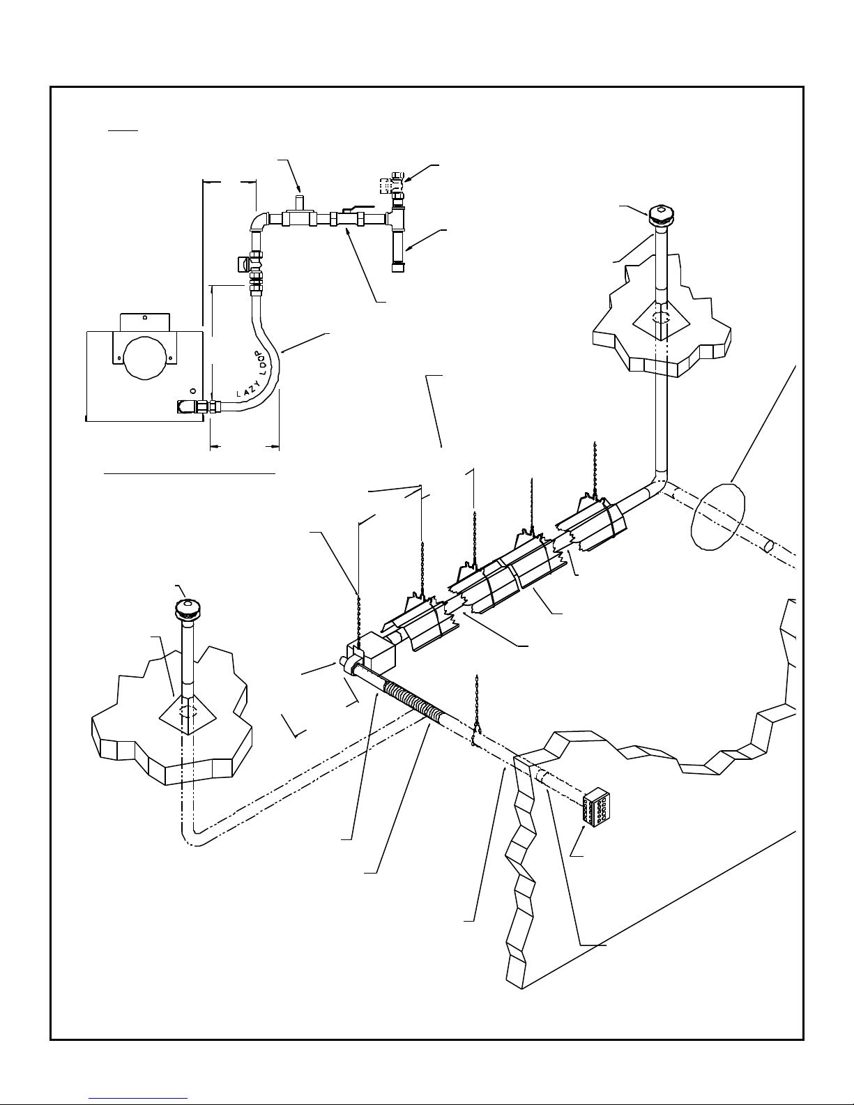
ALL HANGING CHAINS MUST BE PLUMB
AND VERTICAL IN ALL DIRECTIONS WHEN
VENT CAP
MUST BE 6 IN. (15cm)
HIGHER THAN SNOW
DEPTH
ROOF FLASHING
(NOT SUPPLIED)
OVERVIEW DRAWINGS (1 OF 2)
5"
(13cm)
1/2" (1.27cm) O.D. FLEXIBLE GAS CONNECTOR
15"
(38cm)
6.5"
(17cm)
FIRST TUBE SUSPENSION POINT SHOULD BE
(18) IN. (46cm) FROM THE BURNER BOX
INITIALLY INSTALLED
BURNER
12"(30cm) MIN.
24" (61cm) LONG STAINLESS STEEL
CLEARANCE
LOCAL CODES MAY REQUIRE AN ADDITIONAL
SHUT-OFF COCK BE INSTALLED IN THE
GAS LINE AHEAD OF THE DRIP LEG
DRIP LEG
GAS COCK
(SUPPLIED BY OTHERS)
HANGER BRACKETS MUST BE
SPACED AT LEAST 4 FT. (1.2m) APART
WITH (2) BRACKETS FOR EVERY
SECTION OF RADIANT TUBING
4 FT. (1.2m)
MIN.
8FT.
(2.4m)
29 IN.
(74cm)
MAX.
TYP.
VENT CAP MUST BE
6" (15cm) HIGHER
THAN SNOW DEPTH
"B" VENT PIPE ADAPTOR
HEAT EXCHANGER 4 IN.
(10.2cm) O.D. X 5 OR 10 FT.
(1.5m OR 3.0m) LONG
REFLECTOR
INDEPENDENTLY ADJUSTABLE
COMBUSTION CHAMBER
4 IN. (10.2cm) O.D. X 10 FT. (3m) LONG
ADDITIONAL COMBUSTION AIR SUPPLY
SINGLE WALL 26 GA. (.044cm) MINIMUM
GALVANIZED SHEET METAL PIPE OR
SCHEDULE 40 PVC (SEAM TO BE AT TOP)
(NOT SUPPLIED)
INLET AIR SLEEVE
(SEAM TO BE ON TOP)
4 IN. (10.2cm) I.D. FLEX DUCT
18 IN. (46cm) LONG WITH
(2) HOSE CLAMPS
SUPPLY PIPING MUST NOT EXCEED AN EQUIVALENT
OF 35 LINEAR FT. (10.7m) FOR 40-60 MBTUH (11.7-17.6kW).
NO MORE THAN TWO 90° ELBOWS MAY BE USED.
A 90° ELBOW IS EQUIVALENT TO 10 LINEAR FT. (3m).
INLET AIR BOX
(NOT SUPPLIED)
OPTIONAL INLET
AIR SLEEVE (SEAM
TO BE ON TOP)
OVERVIEW DRAWINGS (2 OF 2)
SRH pg. 9
MAINTAIN 18 IN. (46cm) MINIMUM
CLEARANCE TO COMBUSTIBLES
FOR ENTIRE LENGTH OF PIPING
ADDITIONAL EXHAUST VENT PIPING 4" (10.2cm) I.D.
SINGLE WALL 26 GA. (.044cm) MINIMUM GALVANIZED
SHEET METAL (OR OTHER FACTORY-APPROVED
MATERIALS) (SEAM TO BE ON TOP) (NOT SUPPLIED)
MUST NOT EXCEED AN EQUIVALENT OF 35 LINEAR FT.
(10.7m) FOR 40-60 MBTUH (11.7-17.6kW). NO MORE
THAN 2 ELBOWS MAY BE USED. A 90° ELBOW IS
EQUIVALENT TO 10 LINEAR FT. (3m). A 45° ELBOW IS
EQUIVALENT TO 5 LINEAR FT. (1.5m).
2 FT. (61cm) MIN.
4"(10.2cm)
VENT CAP
ASSEMBLY
WALL
VENTING
KIT
WALL BRACE
USE APPROPRIATE FASTENER (NOT SUPPLIED)
FOR ATTACHING TO BUILDING MATERIAL
FOR ALL INDOOR VENT JOINTS: USE RTV SEALANT TO PREVENT HOT FLUE GAS LEAKAGE INTO THE
BUILDING (USE A SHEET METAL PIPE AND CRIMPER FOR JOINING IDENTICAL SIZE SHEET METAL PIPES),
USE THREE (3) #6 SHEET METAL SCREWS (SMS) PER VENT PIPE JOINT. THE VENT PIPE SEAM SHOULD
BE ON TOP WITH ONE SMS ON TOP AND ONE SMS 120 DEGREES FROM THE TOP ON EACH SIDE.
(3) 90 DEGREE BRACES EQUALLY SPACED
FLOW OF HOT GASES
2 FT. (61cm) MINIMUM
CLEARANCE ABOVE OR
BEYOND THE HIGHEST
STRUCTURE OF SURFACE
WITHIN 10 FT. (3m)
OF THE VENT
TUBE WELD SEAM
ON TOP
#12 TEK SCREW
TUBE WELD SEAM
ON TOP
3.0" (7.6cm) MIN.
4.0" (10.2cm) MAX.
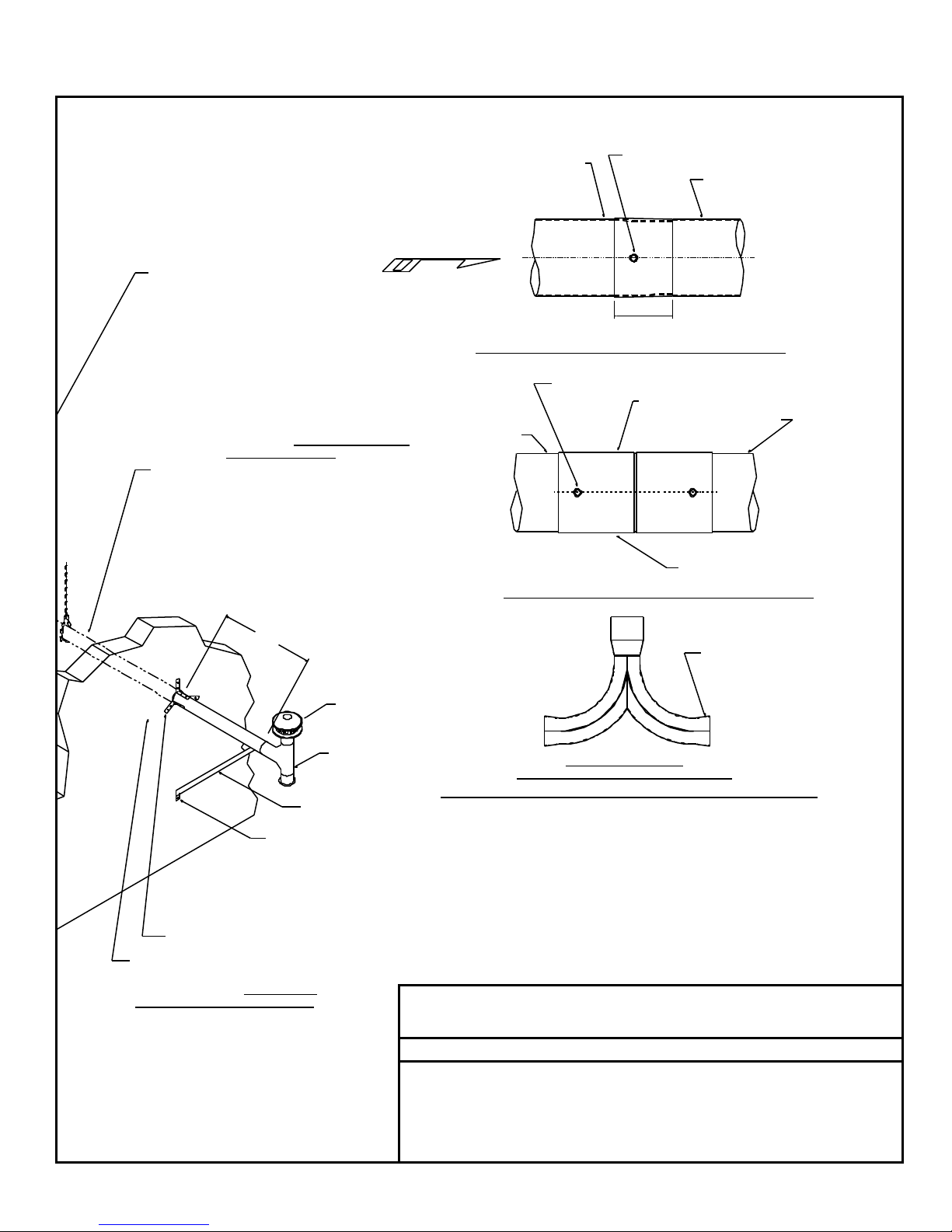
HEAT EXCHANGER MOUNTING ARRANGEMENT
#12 TEK SCREW
4 PLACES
BURNER
WELD SEAM TO BE AT TOP
COMBUSTION CHAMBER
BURNER COUPLER
BURNER COUPLER MOUNTING ARRANGEMENT
FOR ALL JOINTS RTV
SILICONE ADHESIVE
SEALANT SHOULD BE
USED TO PREVENT
LEAKAGE OF HOT
FLUE GASSES.
(10 x 10 x 13cm) (OPTIONAL ACCESSORY)
4" x 4" x 5" Y-COUPLER
OPTIONAL COMMON VENTING THROUGH ROOF OR WALL
BOTH HEATERS MUST BE CONTROLLED
BY A SINGLE THERMOSTAT
FOR COMBUSTIBLE WALLS ONLY
USE A 2" (5.1cm) CLEARANCE
NON-COMBUSTIBLE VENTILATING
METAL THIMBLE (NOT SUPPLIED) .
FOR NON-COMBUSTIBLE WALLS
ONLY 4.25" (10.8cm) DIA. HOLE
FOR 4" (10.2cm) O.D. PIPE ADD
NON-COMBUSTIBLE PROTECTION
AROUND THE HOLE IF NECESSARY.
NOTE
This drawing is for general reference only! It shows only general design
guidelines and it does not provide construction details.
CAUTION
• A U-Tube heater may have a 180 degree U-bend interposed AFTER the
first ten (10) feet (3.0 m).
• Electrical wiring diagrams can be found in the ELECTRICAL SUPPLY
AND THERMOSTATIC CONTROL section.
• The heater must be controlled by a thermostat, timer or other
automatically operated device.

SRH pg. 10
BASIC SYSTEM CONFIGURATIONS
MODEL NO. STRAIGHT TUBE HEATERS
SRHS-40-10AN
SRHS-40-10AL
SRHS-40-15AN
SRHS-40-15AL
SRHS-40-20AN
SRHS-40-20AL
SRHS-45-20AN
SRHS-45-20AL
SRHS-50-20AN
SRHS-50-20AL
SRHS-55-20AN
SRHS-55-20AL
SRHS-60-20AN
SRHS-60-20AL
BURNER
BURNER
BURNER
GQC9
GQC9
GQC1
EXHAUST END
GQH6
EXHAUST END
GQH1
EXHAUST END
MODEL NO. U-TUBE HEATERS
BURNER
GQC9
SRHU-40-15AN
SRHU-40-15AL
GQH6EXHAUST END
SRHU-40-20AN
SRHU-40-20AL
SRHU-45-20AN
BURNER
GQC1
SRHU-45-20AL
SRHU-50-20AN
SRHU-50-20AL
SRHU-55-20AN
GQH1EXHAUST END
SRHU-55-20AL
SRHU-60-20AN
SRHU-60-20AL
U-BEND
U-BEND
REFLECTOR
U-BEND
U-BEND
REFLECTOR

COMBUSTION CHAMBERS/HEAT EXCHANGERS
COMBUSTION CHAMBER COMPONENTS
SRH pg. 11
GQC1
BURNER END
(STENCILED ON TUBE)
GQH1
40,000 thru 60,000 BTUH
(20 foot unit only)
[11.7-17.6kW (6.1m only)]
• 14 ga. (.21cm) aluminized
titanium alloy steel tube
• 10 ft. (3m) aluminum
reflector
• (2) hanger brackets
HEAT EXCHANGER COMPONENTS
40,000 thru 60,000 BTUH
(20 foot unit only)
[11.7-17.6kW (6.1m only)]
GQC9
BURNER END
(STENCILED ON TUBE)
GQH6
40,000 BTUH
(10 and 15 foot units only)
[11.7 kW (3 and 4.6m only)]
EXHAUST END
(STENCILED ON TUBE)
TURBULATOR
(FACTORY
INSTALLED)
WHITE TAPE
• 14 ga. (.21cm) aluminized
titanium alloy steel tube
with turbulator
• 10 ft. (3m) aluminum
reflector
• (2) hanger brackets
40,000 BTUH
(15 foot unit only)
[11.7 kW (3 and 4.6m only)]
EXHAUST END
(STENCILED ON TUBE)
TURBULATOR
(FACTORY
INSTALLED)
• 16ga. (.17cm) aluminized
steel tube with turbulator
• 10 ft. (3m) aluminum
reflector
• (2) hanger brackets
• 5 ft. (1.5m) 16 ga. (.17cm)
aluminized steel tube
• 5 ft. (1.5m) aluminum
reflector
• (2) hanger brackets
10 foot (3m) reflector Hanger bracket
[length approximately 119” (302cm)] (Front view)

SRH pg. 12
COMBUSTION AIR SUPPLY
This heater is NOT an explosion-proof heater. Where the possibility of exposure to
WARNING
• Atmospheric air for combustion may come from either outdoors or indoors (within the building).
• Installation of combustion air supply must comply with the instructions, drawings, and installation notes provided in this
section.
• In buildings contaminated with excessive dust or dirt,
containing substances which when combined with flame
and exhaust products result in corrosive gases, or those
under a negative pressure, combustion air must be
taken from outdoors.
• Outdoor air supply may be accomplished by bringing air
inside through piping from either the roof or wall as
shown below.
• The inlet air roof venting cap (roof) or inlet air box (wall)
must be located at least (3) three feet (1m) away from
any vent termination and in a manner preventing
blockage by snow.
• Components used to bring in outdoor air, when supplied
by others, must be identical to those specified in this
manual and be Metalbestos brand or equal. NO
SUBSTITUTIONS.
• Single wall 4” (10.2cm) I.D. galvanized pipe of 20 gauge
(.035” or 0.9mm) or schedule 40 PVC is recommended
for combustion air supply piping.
• For all systems, total linear (straight) pipe run must not
exceed (35) thirty-five feet (11m) within the building.
• A 90-degree elbow is equivalent to (10) ten linear feet
(3m).
• No more than (2) two 90-degree elbows are permitted.
• It may be necessary to insulate the inlet air supply
piping to eliminate condensation from warm inside air
on the piping.
• In very extreme cases, for protection against any
exterior contaminants, a blower enclosure may be
installed. The outdoor air supply piping is then attached
to the enclosure.
THRU-THE-WALL THRU-THE-ROOF
volatile or low flash point material exists, it could result in severe personal injury, death,
and/or property damage. Consult your local fire marshal or insurance agency to
determine the classification of the building to be heated.
OUTDOORS INDOORS
• When combustion air is to be taken from inside a tightly
sealed or closed building, an opening must be installed
to supply the burner with sufficient air for combustion.
• The opening must be made so that for every 1,000
BTUH (293W) of the total input of all gas-fired
equipment, one square inch (6.5cm2) or more of free
area opening is provided.
• If combustion air is supplied from the space to be
heated, it must be free of contaminants that may
interfere with the proper and safe operation of the
heater. Some contaminants like halogenated
hydrocarbons or other corrosive elements may shorten
the life of the heater.
IMPORTANT
• DO NOT use collapsible material such as dryer duct as
a substitute for single wall galvanized or PVC pipe. It
will restrict air flow to the burner causing improper
operation.
• Inlet air piping must be well supported since additional
stress may be encountered due to be expansion during
heater operation.
• Outdoor air must be free of contaminants.
• A minimum of (3) three feet (1m) is required between
the inlet air roof venting cap and the nearest vertical
vent terminal on a roof.
• If the inlet air roof venting cap is within (10) ten feet
(3m) of a vertical vent terminal on a roof, the vertical
vent terminal must be at least (12) twelve inches
(30.5cm) higher than the inlet air roof venting cap.
INLET AIR SLEEVE
(SEAM TO BE AT TOP)
4 IN. (10.2 CM) I.D. FLEX DUCT
18 IN. (46 CM) LONG
ADDITIONAL 4 IN. (10.2 CM) I.D.
COMBUSTION AIR SUPPLY
PIPING (NOT INCLUDED)
INLET AIR
COLLAR (COMES
WITH BURNER)
TWO HOSE CLAMPS
OPTIONAL INLET
AIR SLEEVE
(SEAM TO BE AT TOP)
STUB
SUPPORT
PIPING AS
NECESSARY
INLET AIR BOX
FRONT PANEL
OF INLET
AIR BOX

SRH pg. 13
EXHAUST VENTING
This heater is NOT an explosion-proof heater. Where the possibility of exposure to
WARNING
• ALL heaters must be directly vented outdoors; NO EXCEPTIONS! Never vent exhaust products indoors.
• Installation of exhaust venting must comply with the instructions, drawings, and installation notes provided
in this section.
DIRECT OUTDOOR VENTING IMPORTANT
• Exhaust venting may be accomplished by passing flue products
through piping in the roof or wall as shown below.
• An inlet air roof venting cap (roof) or inlet air box (wall) must be
located at least (3) three feet (1m) away from any vent
termination and in a manner preventing blockage by snow.
• Components used to exhaust vent outdoors, when supplied by
others, must be identical to those specified in this manual and
be Metalbestos brand or equal. NO SUBSTITUTIONS.
• Use single wall 4” (10.2cm) I.D. galvanized metal pipe of 26
gauge (.018” or 0.46mm) for exhaust vent piping.
• Use RTV silicone adhesive sealant liberally at all vent pipe
joints.
• Use (3) three #6 sheet metal screws per vent pipe joint.
• For all systems, total linear (straight) pipe run must not exceed
(35) thirty-five feet (11m) within the building.
• A 90-degree elbow is equivalent to (10) ten linear feet (3m).
No more than (2) two 90-degree elbows are permitted.
• Allow 18” (46cm) clearance from single wall metal pipe to
combustible materials throughout the entire length of exhaust
vent piping.
• Where a single wall metal pipe passes through a wall/roof of
combustible material, a minimum 2” (5.1cm) clearance noncombustible ventilated metal thimble (not supplied) MUST be
installed in wall/roof at the point of passage. If thimble is not
used, all combustible material MUST be removed a minimum of
18” (46cm) in all directions from the metal pipe.
• Heater must not be vented in between buildings less than (10)
ten feet (3m) apart or above public walkways, doors or
windows.
THRU-THE-WALL OR ROOF EXHAUST VENT DISTANCE FROM:
volatile or low flash point material exists, it could result in severe personal injury, death,
and/or property damage. Consult your local fire marshal or insurance agency to
determine the classification of the building to be heated.
• DO NOT use collapsible material
such as dryer duct as a substitute for
single wall galvanized pipe. It will
melt and/or restrict airflow from the
burner causing improper operation.
• Exhaust vent piping must be well
supported since additional stress
may result due to expansion during
heater operation.
• NEVER vent into a chimney or use a
draft hood, flue collar, or any other
device in the exhaust venting of this
heater!
• A minimum of (3) three feet (1m) is
required between the inlet air cap
and the nearest vertical vent terminal
on a roof.
• The use of double wall ‘B’ vent pipe
inside the building is limited to
equipment with neutral or negative
internal pipe pressure. It is not
recommended for use with this
heater.
• Each vent pipe connecting joint
MUST be sealed to prevent hot flue
gas leakage into the building.
• See OVERVIEW DRAWINGS
section for more venting information.
BELOW
Inches
(cm)
Door N/A 48 (122) N/A
Window 48 (122) 12 (30) N/A
Gravity Air Inlet N/A N/A 12 (30)
Forced Air Inlet
Within 10 ft. (3m)
Grade N/A N/A 12 (30)
Gas Meters &
Electric Meters,
Regulators &
Relief Valves
N/A N/A 36 (91)
N/A 48 (122) N/A
BESIDE
Inches
(cm)
ABOVE
Inches
(cm)

SRH pg. 14
•
•
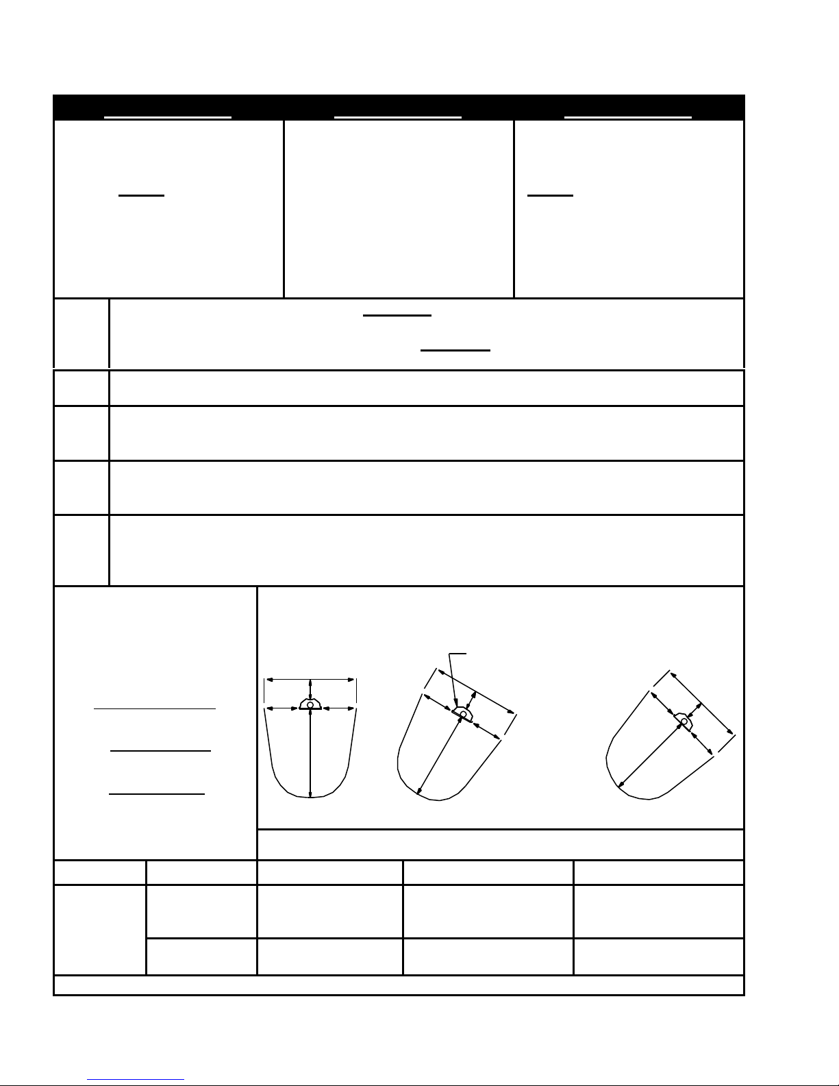
U-TUBE INSTALLATION
A heater may be installed in a U-Tube with its radiant tubes horizontal or with the heat
exchanger angled above the combustion chamber as illustrated by the drawings below.
When radiant tubes are horizontal, reflectors (except at the U-bend) may be individually
rotated from 0 to 45 degrees. (NOTE: the U-bend reflector cannot be rotated.)
HORIZONTAL ANGLED
DO NOT
EXCEED
7.5 IN. (19cm)
0
DEGREES
1 - 45
DEGREES
BASIC SUSPENSION ARRANGEMENT
U-BEND
REFLECTOR
(REQUIRED)

WARNING
SRH pg. 15
U-BEND REFLECTOR INSTALLATION
NEVER operate the U-tube heater WITHOUT the U-bend reflector
assembly installed. Unsafe operation, property damage, personal
injury, and/or death could result!
1. Slide pipe hangers (Item no. 6) over U-bend (Item no. 2).
2. Install Items no. 4, 5, and 6 onto the pipe hanger’s stud.
3. Place U-bend reflector assembly (Item no. 1) over studs.
4. Install Items no. 4, 5, and 6 over the stud on top.
5. Position U-bend with reflector assembly into combustion chamber and heat exchanger up
to the colored indicators.
6. Use (4) four #12 multi-metal self-drilling screws (supplied with U-bend) to fasten U-bend
to combustion chamber and heat exchanger.
INSTRUCTIONS

SRH pg. 16
TUBE ASSEMBLY TIPS (1 OF 2)
Experienced installers have made recommendations to
simplify the installation of these tubes by reducing the
number of connections to be made up in the air
Most important:
• Do not drag the tubes and dent the connecting ends!
• ALIGN THE WELD SEAMS OF ALL THE TUBES and make
sure they are on top when joining tubes!
COLOR INSERTION INDICATOR
ALL WELD SEAMS
MUST BE LINED UP
TOGETHER
SWAGED END
PILOT HOLE
FLARED END
AIR FLOW
#1 Place two (2) ten (10) foot (3m) sections on the floor and align
the weld seams on top. (Properly orient the “BURNER
END”/”EXHAUST END” markings on the combustion and exhaust
end tubes).
ALIGN ALL THE WELD SEAMS IN A LINE TOGETHER!
WELD
SEAM
WOOD BLOCK
2X4 IN. (5X10 CM)
STURDY WALL
SWAGED END
COLOR INSERTION INDICATOR
PILOT HOLE
FLARED END
2X4 IN. (5X10 CM)
WELD
SEAM
WOOD BLOCK
#2 Position a 2X4 in. (5x10 cm) block of wood on each of the far
ends of both tubes.
• One block of wood prevents damage to the connecting end that
will be used to tap that tube into the other.
• The other block of wood prevents damage to the other
connecting end that is butted up to a nearby sturdy wall.

TUBE ASSEMBLY TIPS (2 OF 2)
#3 Manually slide the male end of one tube into the female end of
the other tube. ALIGN THE WELD SEAMS ON BOTH TUBES
TOGETHER. STRAIGHTEN the two (2) tubes and proceed to tap
one tube into the other by hitting the wooden 2X4 in. (5x10 cm)
block, NOT the tube! Continue to tap one tube into the other until
the flared end comes up to, but does not cover the color insertion
indicator.
STRAIGHTEN BEFORE DRIVING SCREWS
WRONG - NOT STRAIGHT
SRH pg. 17
RIGHT - STRAIGHT
#4 STRAIGHTEN the tubes again BEFORE driving the
screws. Ensure all tubes are straight and level with the weld
seam on top before installing the screws. Drive with a power tool
the two (2) #12 MULTI-METAL Tek screws into the joint and
position the four (4) hangers on the twenty (20) foot (6.1m)
section.
#5 Attach a temporary rope or chain to the two (2) outer brackets
and hoist the twenty (20) foot (6.1m) section into the air. Align the
weld seam on top, level the section, and install the chain on the
hangers.
Complete the total installation according to this manual. Use these
tips along with the instructions in the INSTALLATION section. Use
the U-TUBE INSTALLATION and the U-BEND REFLECTOR
INSTALLATION sections as necessary.

SRH pg. 18
INSTALLATION (1 OF 2)
CAUTION
• DO NOT use gas piping or electrical conduit to provide any type of support for the heater’s suspension.
• Means of suspension MUST BE able to support twice the weight of the heater, securely fastened to the building’s
structure, and allow for expansion during its operation.
• Chain for suspension MUST BE 12 in. (31cm) minimum in length and be 1/0 TENSO with a minimum working load rating
of 200 lbs. (90.7 kg).
• The “S” hook MUST BE Chicago Hardware no. 5 or equal and carry a 70 pound (32kg) maximum load.
STEP
1
STEP
2
STEP
3
STEP
• Use a taut string in the planning of suspension points to maintain straightness over the length of the system.
Make true right angles if elbows are used.
• Check the BASIC SYSTEM CONFIGURATIONS section for the general orientation of components matching
the model number of your system.
• Identify all components in the COMBUSTION CHAMBERS and HEAT EXCHANGERS sections.
• U-type systems use a 180-degree U-bend. See U-TUBE INSTALLATION section.
• Install chain for suspension of tubes and reflectors.
• The suspension points for each 10-foot (3.0m) tube should be a
minimum of 4 feet (1.2m) and a maximum of 6 feet (1.8m) apart.
• Use a minimum of 12 in. (31cm) of chain for each suspension point.
• Install a chain to be positioned at the joint between the combustion
chamber and the burner.
• Install an additional suspension point, for a required safety chain at
the back of the burner box 17.5 in. (44cm) from the joint between the
combustion chamber and the burner.
• Install tube/reflector hangers. Slip one end of the S-hook through
the last chain link and the other end through the tube/reflector
hanger.
• IMPORTANT: Crimp both ends of the S-hook closed!
• Identify all components in COMBUSTION CHAMBERS
and HEAT EXCHANGERS sections of this manual.
• Check the BASIC SYSTEM CONFIGURATIONS section
of this manual for the general orientation of components
matching the model number of your system.
• Systems fifteen (15) feet (4.6m) or longer require joining
together of combustion chamber and heat exchanger
tube(s). See TUBE ASSEMBLY TIPS section.
• For U-type systems, a 180-degree u-bend is also used.
See U-TUBE INSTALLATION section.
• Slip the burner coupling over the end of the combustion
chamber marked “BURNER END”.
• Rotate the burner coupling until the two holes on one end
of the coupling are each 90 degrees apart from the weld
seam on the combustion chamber and seat it against the
center stop.
• Use (2) #12 MULTI-METAL Tek screws (supplied with the
coupling) to fasten the coupling to the combustion
chamber.
• Tubes MUST NOT be dragged along the ground or other
surfaces which may damage the ends.
• Take this assembly, with the weld seam still facing up, and place the end marked “BURNER END” into the
first two suspended hanger bracket assemblies at the point where the burner will eventually be located.
• Place a reflector (gloves are suggested; handle the reflectors with care as not to soil the shiny underside) over
the combustion chamber and into the suspended hanger bracket assemblies.
BURNER
COUPLER
#12 TEK SCREWS
(2 PLACES)
WELD
SEAM
COMBUSTION CHAMBER
MARKED "BURNER END"
WELD
SEAM
4
BURNER END
(STENCILED ON TUBE)
• Heaters shall NOT be installed in living/sleeping areas.
WARNING

STEP
5
SRH pg. 19
INSTALLATION (2 OF 2)
• The next heat exchanger tube, with it’s weld seam up, [for 15 ft. and 20 ft. (4.6 and 6.1 m) systems only] can
be put into the respective suspended hanger bracket assemblies.
• Manually push the flared end of the heat exchanger tube [it has two (2) holes in it] over the swaged end of the
combustion chamber as far as you can.
• [NOTE: The swaged end of the combustion chamber has a colored line 3 in. (7.6 cm) from the end].
COLOR INSERTION INDICATOR
STEP
6
STEP
7
SWAGED END
AIR FLOW
• Go to the swaged end of the heat exchanger tube, and with a 2 pound (0.9kg) hammer and a two (2) in. by
four (4) in. (5 cm x 10 cm) block of wood, hit the end of the tube until you have 3 in. (7.6cm) of insertion (the
colored line will still be visible).
• Ensure all tubes are straight and level with the weld seam at the top before installing the screws. See
the TUBE ASSEMBLY TIPS Section for more information.
• Tek screw the tube joint connection through the two holes provided in the flared end with (2) two #12 MULTI-
METAL Tek screws (supplied with the tube).
• Place a reflector over the heat exchanger and into the suspended hanger bracket assemblies.
WELD SEAM MUST BE ON TOP
FLARED END COMES UP TO, BUT DOES NOT
COVER COLOR INSERTION INDICATOR
• Slip the burner’s tube into the burner coupler previously installed in Step 4.
• Once the burner is level, straight and inserted against the center stop, use (2) two #12 MULTI-METAL Tek
screws (supplied with the coupling) to fasten the burner to the coupling.
• Insert the “S” hook of the burner support chain into the center hole of the burner suspension bracket and then
crimp the hook closed.
BURNER
SUPPORT
CHAIN
PILOT HOLE
FLARED END
#12 MULTI-METAL SELF
DRILLING SCREWS (2 EA.)
BURNER
COUPLER
STEP
• Reflectors must not be angle mounted more than 45°
from horizontal.
8
WARNING IMPORTANT
• The # 12 MULTI-METAL Tek screws supplied with the coupling
MUST NOT be substituted with any other type of Tek screw. If
you loose them, contact the factory for new ones.
CAUTION
• Make sure all chains are plumb and vertical to prevent damage
to tubes.
BURNER
#12 MULTI-METAL SELF
DRILLING SCREWS (4 EA.)
• Connect the gas supply as instructed in the GAS
SUPPLY AND GAS PRESSURE section.
• Connect the electrical supply as instructed in the
ELECTRICAL SUPPLY AND THERMOSTATIC
CONTROL section.

SRH pg. 20
ELECTRICAL SUPPLY AND THERMOSTATIC CONTROL (1 OF 2)
ELECTRICAL SUPPLY 120 VAC SUPPLY & 120 VAC THERMOSTATIC CONTROL
• Voltage: 120VAC - 1 phase - 60 Hz.
• Maximum Amps: 3.0 (1.47 actual full
load)
• Flame safety: Electronic.
• Ignition: Direct Spark.
• Wiring must conform to the latest
edition of the National Electric Code
(ANSI/NFPA 70) or local code legally
authorized.
• Electrical power takeoff must be
connected to a separately fused circuit
with a disconnect or a circuit breaker,
and must be properly polarized and
grounded to the heaters power cord.
• Do not run wiring over the heaters or in
direct view of radiant heat.
• If any of the wiring supplied must be
replaced use type 16 AWG (1.0mm2),
or equivalent with 2/64” (.08cm)
insulation and a minimum insulation
temperature of 302°F (150°C).
WARNING 120 VAC SUPPLY & 24 VAC THERMOSTATIC CONTROL
• ELECTRICAL GROUNDING
INSTRUCTIONS. This heater is
equipped with a three-prong
(grounding) plug for your protection
against shock hazard and should be
plugged directly into a properly
grounded three-prong receptacle. DO
NOT cut or remove the grounding
prong from this plug.
IMPORTANT
• The Residential Heater (RH) MUST be
controlled by a thermostat, timer, or
other automatically operated device.
PROPER GROUNDING AND POLARITY ARE ESSENTIAL
TO THE SAFE OPERATION OF THE HEATER.
(GROUND)
GREEN
(NEUTRAL)
WHITE
(HOT)
BLACK
(3 WIRE SERVICE)
120 VAC - 1 PHASE - 60 HERTZ
WIRING BY INSTALLER
NOTE: ALL COMPONENTS SUPPLIED BY OTHERS.
PROPER GROUNDING AND POLARITY ARE ESSENTIAL
TO THE SAFE OPERATION OF THE HEATER.
(HOT)
BLACK
(NEUTRAL)
WHITE
(GROUND)
GREEN
(3 WIRE SERVICE)
120 VAC - 1 PHASE - 60 HERTZ
BLACK
BLACK
WHITE
120 VOLT
THERMOSTAT
TRANSFORMER/RELAY
(MOUNTED TO 4X4
JUNCTION BOX
PROVIDED BY OTHERS)
R
W
G
Y
C
RECEPTACLE
(BY OTHERS)
FACTORY SUPPLIED
POWER CORD
FROM BURNER
RED (HOT)
BROWN
GENERAL INSTALLATION NOTES
• Locate the thermostat as specified in
the heating plan.
• If it is not in the heating plan, follow the
instructions provided with the
thermostat.
• If instructions are not provided with the
thermostat, locate it 4 to 5 feet (120 to
150cm) above the floor where it will
not be directly affected by the heat
from the heater, outside drafts, or the
sun.
24 VOLT THERMOSTAT
GREEN GROUND
SCREW IN 4X4
JUNCTION BOX
WIRE NUT SYMBOL
WIRING BY INSTALLER
NOTE: ALL COMPONENTS SUPPLIED BY OTHERS.
(NEUTRAL)
(GROUND)
FACTORY SUPPLIED
RECEPTACLE
(BY OTHERS)
POWER CORD
FROM BURNER

SRH pg. 21
ELECTRICAL SUPPLY AND THERMOSTATIC CONTROL (2 OF 2)
SEQUENCE OF OPERATION BURNER WIRING SCHEMATIC/INTERCONNECTION DIAGRAM
• When the 120 VAC thermostat calls for
heat, power is applied to the factory
supplied power cord, or when the 24
VAC thermostat calls for heat, the
relay is energized applying 120 VAC to
the factory supplied power cord.
• 120 VAC is applied to the blower and
validation light PL-1 indicates power is
ON.
• Air flow switch closes contacts after it
senses an increase in air pressure due
to fan reaching operational speed.
• Validation light PL-2 indicates
combustion air supply and exhaust
venting back pressure is normal.
• Ignition Detection Control (IDC) is
turned on and begins a 15-second prepurge time period.
• The pre-purge period is followed by a
15-second trial for ignition during
which a spark is developed at the
igniter and the gas valve is opened to
the first step of its two step operation.
• Burner ignites and 5 seconds later the
gas valve steps up to its operating
position. DC electrical current flows
from sensing electrode through flame
to ground.
• IDC senses flame presence, turns
OFF spark, gas continues flowing
through valve.
• Validation light PL-3 indicates normal
burner operation.
• During first trial-for-ignition period or
upon any flame outage at sensing
electrode, the IDC responds and
begins sparking within 0.8 seconds. A
15-second trial-for-ignition period
begins to re-light the burner. If flame
is re-established, normal operation
resumes. If the burner does not light
after first try, the inter-purge sequence
is completed between trials to re-light
the burner. If the burner fails to light
(10DX-117) or after third trial (35-725),
IDC will de-energize the valve and go
into lockout mode.
• For lockout recovery, reset thermostat
below ambient temperature or
disconnect electrical power supply for
5 seconds. If the flame does fail during
ignition or normal operation, it is
detected by the flame sensor rod, and
the IDC then closes the gas valve
locking out the system until the
thermostat is cycled to the OFF
position.
• When the thermostat is satisfied, the
whole system is de-energized until
another call for heat.
• When installing or servicing this
heater, wait at least 5 minutes
between attempts for ignition.
If any of the original wire as supplied with the appliance must be replaced, it must be replaced with wiring material
having a temperature rating of at least 302°F (150°C) and shall have a minimum size of 16 AWG.
115V.-1PH.-60HZ.
WHITE
BLACK
BLACK
BLACK
GAS VALVE
SENSOR
GROUND
SPARK
(+)
(-)
(HOT)
(NEUTRAL)
WHITE
BLACK
BLACK
BLACK
RED
AIR FLOW SWITCH
RED
IDC
(35-725)
- WIRE NUT SYMBOL
PL-1
N
BLACK
BLACK
GREEN
RED
WHITE
BLACK
WHITE
YELLOW
HIGH VOLTAGE LEAD WIRE
GREEN
GROUND
SCREW
PL-2
N
FAN MOTOR
BLACK
YELLOW
PL-3
N
BLACK WHITE
GREEN
WHITE
BURNER WIRING LADDER DIAGRAM
If any of the original wire as supplied with the appliance must be replaced, it must be replaced with wiring material
having a temperature rating of at least 302°F (150°C) and shall have a minimum size of 16 AWG.
120V.-1PH.-60HZ.
BLACK
BLACK
BLACK
AF-1
RED
AIR FLOW SWITCH
IDC
35-725
RED
GREEN
RED
WHITE
BLACK
WHITE
YELLOW
(+) (-)
(GROUND)
(HOT) (NEUTRAL)
FAN MOTOR
BLACK
BLACK
BLACK
HI-VOLTAGE WIRE
CHASSIS GROUND
GREEN
PL-1
PL-2
PL-3
GAS VALVE
WHITE
BLACK
WHITE
BLACK
BLACK
WHITE
POWER ON
FAN
MOTOR
AIR
PRESSURE
NORMAL
BURNER
OPERATION
NORMAL
GAS VALVE
SENSOR
GROUND
SPARK
(GROUND)
GREEN

SRH pg. 22
GAS SUPPLY AND GAS PRESSURE
GAS SUPPLY PIPING INLET GAS PRESSURE
• Piping must be installed in accordance with local codes
and/or ANSI Z223.1-latest edition (NFPA 54-latest
edition, National Fuel Gas Code.
• Piping must have drip leg and a ground joint union.
• All pipe connections must have pipe joint compound,
resistant to LP/propane gas action.
• Isolate regulators, flexible gas connectors, and heaters
during high-pressure leak testing above ½ psig (35.6cm
water column).
• All gas lines must be purged before startup.
• Use only agency approved flexible gas connector with
shut-off cock for connecting to the heater. (SEE
CAUTION: LAZY LOOP).
• Use swing or swivel joint in addition to rigid piping if local
codes prohibit use of a flexible connector.
• Local codes may require additional shut-off cock ahead
of the drip leg.
CAUTION: LAZY LOOP HIGH INLET GAS PRESSURE
• Stress from expansion and contraction of heater may
cause excessive wear on the gas connection.
• For a heater 20 feet (6.1m) long, heater tubes can
expand up to 1.1” (2.8cm).
• If local codes permit, flexible gas connectors must be in
a “LAZY LOOP” arrangement as shown on the drawing
below.
• It is important to maintain dimensions as shown on
drawing below.
GAS PRESSURE MEASUREMENTS
• Use only a water or red oil manometer to make
measurements --- NOT A DIAL GAUGE.
• Make measurements and adjustments when this heater
and ALL other gas burning equipment connected to the
same gas meter are operating at maximum capacity.
NOTE:
WHEN GAS PRESSURE
EXCEEDS 14" (35.6cm) W.C.,
A FIRST STAGE REGULATOR
MUST BE INSTALLED.
5"
(12.7cm)
15"
(38cm)
6-1/2"
(16.5cm)
1/2" (1.27cm) O.D. FLEXIBLE
GAS CONNECTOR
24" (61cm) LONG
STAINLESS STEEL
LOCAL CODES MAY REQUIRE
AN ADDITIONAL SHUT-OFF COCK
AND 1/8" NPT PLUGGED TAPPING,
ACCESSIBLE FOR TEST GAGE CONNECTION,
BE INSTALLED IN THE GAS LINE
AHEAD OF THE DRIP LEG
DRIP LEG
GAS COCK
(SUPPLIED BY OTHERS)
EXCESSIVE TORQUE ON THE BURNER
GAS INLET MANIFOLD PIPE MAY CAUSE
DAMAGE TO BURNER. ALWAYS USE TWO
(2) WRENCHES WHEN MAKING PIPE
CONNECTIONS. IMPORTANT: CHECK
FOR LEAKS WITH SOAP SOLUTION ---
DO NOT USE FLAMES!!
• Inlet gas pressure must be measured on the inlet side of
the valve at test point ‘A’ in the supply piping and must
conform to the following:
MINIMUM
GAS TYPE INLET PRESSURE
Natural 6” WC (15.2cm WC)
LP/Propane 11” WC (27.9cm WC)
MAXIMUM
GAS TYPE INLET PRESSURE
Natural 14” WC (35.6cm WC)
LP/Propane 14” WC (35.6cm WC)
IMPORTANT
• Gas pressure at test point ‘A’ inlet pressure to the
burner’s gas valve cannot be more than 14 inches of
water column (in. WC) (35.6cm WC) (1/2 PSI), confirmed
by actual field test. (Heater on or off).
• If inlet pressure is greater than 14” WC (35.6cm WC), a
positive lockout type high-pressure regulator must be
installed in the gas line ahead of the burner.
• Always check local codes for gas venting requirements
of high gas pressure regulators.
MANIFOLD OUTLET GAS PRESSURE
• Fluctuations in the inlet pressure can alter the manifold
pressure coming out of the gas valve.
• For manifold pressure adjustment location, refer to
drawing below.
• Remove the pipe plug from test point ‘B’; insert a barb
fitting connected to the manometer.
• For all heaters, remove the slotted cap screw.
• Turn adjustment screw clockwise to increase pressure or
counterclockwise to decrease pressure.
• All RH heaters operate using a manifold pressure of
3.5” WC (8.9cm WC).
BURNER
SUPPORT
CHAIN
MANIFOLD PRESSURE
ADJUSTMENT (WHITE
RODGERS VALVE)
TEST POINT 'A'
(INLET)
CAUTION
TEST POINT 'B'
(OUTLET)
RECOMMENDED GAS CONNECTION ARRANGEMENT USING A FLEXIBLE GAS CONNECTOR

STARTUP
STARTUP IMPORTANT
SRH pg. 23
• Remove the burner cover by removing the 4 sheet
metal screws from the topside of the burner cover.
• Remove the 1/8 NPT pipe plug from Test Point B and
connect manometer. Refer to the drawing in the GAS
SUPPLY AND GAS PRESSURE section.
• Depress the dial on the gas valve, and make sure the
gas valve is in the ON position.
• Turn on the electrical and gas supply and set the
thermostat above the ambient room temperature, to call
for heat.
• Refer to the ELECTRICAL SUPPLY AND
THERMOSTATIC CONTROL section for proper
sequence of operation.
• If the heater does not operate normally, refer to the
BURNER TROUBLESHOOTING section to diagnose
and correct the situation.
• Turn gas and electrical supply off, remove the
manometer and replace the 1/8 NPT pipe plug into Test
Point B on the gas valve.
• Check again for gas leaks. Refer to GAS SUPPLY
AND GAS PRESSURE section as needed.
• Cycle the heater several times by means of the
thermostat, allowing at least five minutes between
cycles. If the heater operates normally, replace the
burner cover and screws.
• If the heater is vented directly outdoors, observe and
verify the flue gases exiting from the exhaust vent are
not impinging on building construction.
• Check and, if necessary, adjust the manifold pressure!
.156 IN. (3.96 CM)
SPARK GAP
± 1/32 IN. (.08 CM)
.208'' (.53 CM)
GROUND GAP
REF.
SAFETY CHAIN BRACKET
BLOWER
INLET
AIR
COLLAR
AIR ORIFICE
(3) THREE NEON
VALIDATION LIGHTS
(3) THREE PRING PLUG
WITH 36 IN. (91CM)
LENGTH CORD
TUBING ADAPTOR
BURNER CORE ASS'Y
MAIN ORIFICE
VINYL TUBING
IGNITION DETECTION
CONTROL
IGNITION LEAD WIRE
AIR FLOW SWITCH
AIR FLOW SWITCH TUBING CONNECTIONS
THE SWITCH "+" OR "HIGH" SIDE TUBE GOES TOWARD THE BLOWER SIDE.
THE SWITCH "-" OR "LOW" SIDE TUBE GOES TOWARD THE IGNITOR SIDE.
BURNER NOZZLE
IGNITOR BRACKET
SHEET METAL SCREW
OBSERVATION PORT
1/2" NPT GAS INLET
GAS VALVE

SRH pg. 24
BURNER TROUBLESHOOTING (1 OF 2)
Replace pressure switch.
NONO
YES
Check thermostat and wiring.
Find problem and correct it.
Is the blower wheel
damaged or dirty?
Clean or repair wheel.
NO
Adjust spark gap.
Replace combination gas
valves on each heater.
NO
Were heaters isolated during
high pressure leak testing?
YES
Disconnect flex hose at each heater until
gas is present. Connect flex hose and leak test.
NO
YES
Have all gas lines been
completely bled of air?
YES
YES
Replace blower.
Is the power supply to
heater 115 VAC?
NO
YES
Replace fuse.
Is the power supply to
the heater fused?
NO
Replace piping as required.
Are inlet and exhaust piping
the proper size and length?
NO NO
Replace as required.
NO
NO
YES
(refer to manual)
YES
Do the termination fittings
meet factory specifications?
Is airflow tubing or its
snubber orifice blocked?
Is inlet or exhaust blocked?
YES
Clear blockage.
(check both tubes)
NO
YES
Clear blockage.
NO
Check for loose wire or
connector and correct
the problem.
NO
YES
YES
Replace IDC box.
Check high voltage wire.
Is it okay?
Is there 115 VAC at the ignition
detection control?
Replace ignitor.
YES
Is the spark gap
Replace ignitor.
5/32 in. [.156" (.396cm)]?
YES
2
Is the ignitor sparking
at the tips?
NO NO NO
NO
Is this a new installation?
NO
Energize the system
light come on?
Does the blower / PL-1
YES
YES
Does the pressure switch
close / PL-2 light come
on?
YES
Does the ignitor spark /
PL-3 light come on?
YES
1
Does the burner ignite?
(There are 3 trials-for-ignition
before IDC goes into lockout).

BURNER TROUBLESHOOTING (2 OF 2)
the correct size pipe.
Replace inlet gas piping with
NO
Turn gas valve to
the on position.
NO
NO NO
Replace the IDC box.
Is there 115 VAC coming
from the IDC box?
SRH pg. 25
NO
Open all manual gas valves.
Make sure combination gas
valve at the heater is on.
NO
YES
2
Is the gas supply
turned on?
1
YES
Is inlet gas piping sized
correctly? (see manual)
NO
Is the gas inlet pressure
correct? (see serial plate)
Adjust supply regulator to
increase or decrease inlet
YES
YES
Is the combination gas valve
pressure to proper level.
(see serial plate)
in the on position?
NO
Is there outlet (manifold) gas
pressure at the gas valve?
YES YES
Replace gas valve. Replace gas valve.
Is there 115 VAC at
the gas valve?
YES
Adjust regulator
on gas valve.
NO
YES
Is the outlet (manifold) gas
pressure correct?
(see serial plate)
Check the main and sub gas orifices for blockage by spider webs.
Check the gas orifices and air orifice for correct sizes.
YES
Install true earth ground
to power supply.
YES
Is the power supply grounded
to a true earth ground?
NO NO
YES
Is flame signal at
least -17 VDC?
Replace IDC box.
NO
YES
Is flame sensor wire
loose or damaged?
Replace wire harness
to IDC box.
YES
NO
YES
Does the spark stop when
the burner lights?
TROUBLESHOOT ENDS
Does the burner stay lit until
the thermostat is satisfied?

SRH pg. 26
MAINTENANCE
• FOR SAFETY REASONS, BEFORE PERFORMING ANY MAINTENANCE, DISCONNECT AND LOCKOUT
THE ELECTRICAL SUPPLY BY POSITIVE MEANS.
• All maintenance and/or repair MUST be performed by someone trained and qualified to work on gas and electrical
equipment.
• Annual maintenance done prior to the beginning of each heating season is all that is usually necessary.
• In dirty, dusty, or wet atmospheres, it may be necessary to examine and perform needed maintenance at additional times
during the middle of the heating season. Experience will dictate the frequency.
• Radiant tubes, combustion air ducting, and exhaust venting should be inspected to make sure that: suspension points are
secure, tube clamp nuts are tight, heater is level, chains are plumb and taut (except for burner safety chain), vent pipe
joints are properly sealed, “S” hooks are crimped closed, there is no excessive exterior buildup of dust or dirt, and make
sure there are no restrictions such as bird or insect nests in the combustion air or vent piping.
• Reflectors should be inspected to make sure they are clean and secure, as detailed in the INSTALLATION section. If
dirty, reflectors should be removed and washed with isopropyl alcohol, Simple Green, or buffed with mild rubbing
compound.
• On U-tube systems the U-bend reflector support nuts should be inspected to make sure they are tight.
• Inspect the inside of the blower enclosure for excessive dust or dirt buildup on the impeller wheel and make sure the air
orifice and the inlet air collar are properly attached. Check that the blower can come up to full speed.
• Remove the cover by removing the 4 sheet metal screws on top of the cover.
• Remove the ignitor by removing ONLY the end where the vinyl tubing is attached to the ignitor bracket; the fitting to which
the vinyl tubing was connected; the ignition lead wire from the ignition detection control; and the sheet metal screw
holding the ignitor bracket to the burner housing wall.
• Remove the ignitor carefully; its’ electrodes make a ninety degree turn to the right.
• Clean the ignitor’s porcelain insulation and check for cracks and proper gaps (see STARTUP section).
• Within the interior of the burner tube, examine the burner nozzle, primary air holes, main orifice and surrounding area for
build up of dust or dirt. Clean if necessary.
• Reinstall the ignitor by following these instructions in reverse order.
• Examine the ignition detection control for overheating (warped plastic housing, discoloration, etc.)
• A visual inspection of gas valve, airflow switch, and wiring is adequate.
• Inside each clear vinyl tube used for air flow sensing is a small snubber (aluminum cylinder piece). Visually inspect for
cleanliness.
• Clean any surfaces needed and correct any situations found in disrepair.
• Replace the cover and sheet metal screws.
• The blower motor is of the permanently lubricated type and requires no additional lubrication.
• Double check that the area under the heater is kept clear and free from combustible materials, gasoline, and other
flammable vapors and liquids.
• Reconnect electrical supply and cycle the heater several times using the thermostat allowing (5) five minutes between
cycles for proper operation.

REPLACEMENT PARTS
1. Gas valve 12. Safety chain bracket with nuts
2. Gas manifold assembly with fittings 13. Blower motor
SRH pg. 27
3. Air flow switch (combustion) tubing assembly with
snubber and fittings
4. Burner core 15. Power cord strain relief bushing
5. Ignitor gasket 16. System validation light
6. Ignitor 17. Ignition detection control
7. Air flow switch (exhaust) tubing assembly with snubber
and fittings
8. Air flow switch 19. Wire harness assembly
9. Burner cover 20. Gas manifold fitting (at valve)
10. Inlet combustion air collar 21. Gas sub orifice
11. Air orifice plate 22. Gas main orifice (located inside of burner tube)
14. 36” (91 cm) long power cord with 3-prong grounded plug
18. Burner tube holding bracket with screws
!!! WARNING !!!
Any substitutions of factory-installed parts without prior written
permission may result in unsafe operation, property damage, personal
injury, death, voids CSA design certification, and manufacturer’s warranty.
Due to continuous product improvement, please provide serial and model number prior
to ordering replacement parts to assure safe repairs and maintenance.

FOR SERVICE OR REPAIR, FOLLOW THESE STEPS IN ORDER:
FIRST: Contact the Installer
Name __________________________________________________
Address ________________________________________________
________________________________________________________
________________________________________________________
Phone __________________________________________________
SECOND: Contact the Nearest Distributor
Model No.: ______________________________________________
Unit Serial No.: ___________________________________________
Date of Installation: ________________________________________
P.O. Box 80217, Rochester MI 48308-0217
Toll Free: 1-866-664-3824
FAX: (248) 651-0357
 Loading...