

Page 1
Sunshine
Gel Time Meter 22A
Manual
Page 2

APPLICATION:
The GEL TIME METER is a self-indicating device for measuring the gel time of a thermosetting fluid composition, i.e., the time at a
constant temperature for the material to reach the incipient gelled state. This point is usually characterized by a sudden, pronounced increase in the viscosity of the material. It is registered by the instrument through the closing of an electrical gap actuated by the torsion exerted on a slowly rotating spindle suspended in the test sample. Materials exhibiting this thermosetting property, by which they may be evaluated, include monomers, resins, potting compounds, melamine formaldehydes, styrenes, waxes,
varnishes, unsaturated oils (i.e. tung oil) etc.
The gel time for a particular composition under well-controlled conditions may be reproduced by the instrument to within plus or
minus one percent. Since the gel time is temperature dependent, the temperature at which each gel time is determined should
always be controlled.
In a sense, the gel time value is a measure of the relative reactivity of material that undergo gelation; therefore, the instrument
offers a convenient means of assigning a number to each material characterizing its reactivity under the test condition. This number is given in terms of minutes at a particular temperature. In the evaluation of reactivity, of course, a shorter gel time indicates a
greater reactivity, while a longer gel time signifies a lesser degree of reactivity.
The measurement of gel time is of considerable importance to quality control work. It also affords a means of studying the effect
of such variables as:
A. Composition
B. Reaction Temperature
C. Concentration and kind of catalyst, accelerator, inhibitor, retardant, diluent, etc.
D. Storage and shelf life
Furthermore, the shelf life of a composition at room temperature may also be estimated by determining the gel time at two or
more elevated temperatures and extrapolating to room temperature. This may be accomplished by plotting a log of gel time vs.
1/T, where T equals absolute temperature. The points should fall on a straight line.
In addition, the instrument can also be used to measure the "thickening times" of liquid materials which do not gel but undergo a
substantial increase in viscosity during heating. In this case, the thickening time is the time for the material to reach an arbitrarily
chosen viscosity sufficient to close a certain setting of the electrical gap.
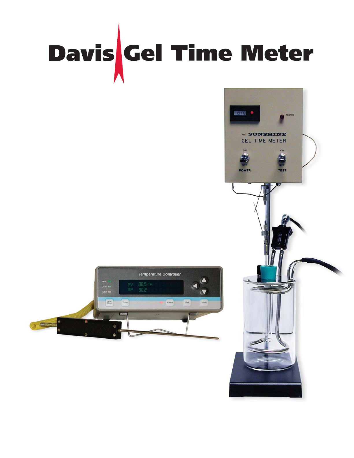
DESCRIPTION:
The principal parts of the Gel Time Meter are: a constant temperature bath into which the test sample, contained in a test tube, is
immersed; a rotating spindle (glass rod) suspended in the sample from a torsion wire driven by a one rpm synchronous motor;
electrical contacts across the torsion wire connected to the control unit; a time counter, a buzzer and a signal light to provide both
an audible and a visible alarm when the gel point has been reached.
BATH:
In the determination of gel time, it is essential to maintain the boiling bath at a known constant temperature. Regulation of boiling
rate is obtained by means of a variable transformer (SSI V22 available as an extra) connected to the 650 watt immersion heater. A
convenient working temperature is 100 C, obtained by using water. When it is desirable to work at lower temperatures, another
non-flammable liquid such as methylene chloride (b.p. 40 C), chloroform (b.p. 61 C), carbon tetrachloride (b.p. 77 C), or a mixture
of this can be used. Temperatures above 100 C can be obtained with other liquids. When using temperatures other than boiling
points, the Davis Calibration Temperature Controller (cat. #2295A with 2296 T/C) can be used to keep the temperature constant.
1
Page 3

CAUTION:
WHENEVER A BATH IS USED WHICH EMITS TOXIC VAPORS,THE OPERATION SHOULD BE CARRIED OUT UNDER A SUITABLE
HOOD. FOR REASONS OF SAFETY,THE USE OF FLAMMABLE LIQUIDS IN THE BOILING BATH IS NOT RECOMMENDED.
TORSIONAL SPRING:
The very heart of the Gel Time Meter is the torsional spring suspension. The fixed stiffness of this spring, referred to as the spring
constant, must be accurately maintained. It is realized by the use of a special torsion wire that is connected to an upper vise
assembly and a lower vise and magnet assembly.
ACTUATING SWITCH:
The switch referred to previously is an electrical gap, which, when closed, actuates the alarm and timing circuits. It consists of
two contacts that are fixed to the opposite ends of the torsional wire spring (Fig. 1). These contacts are adjusted to form a 3/32"
gap with no load. As variation in gap distance will somewhat affect the gel time, it is necessary to maintain this dimension.
Adjusting is necessary to maintain this dimension. Adjustment is made with the lower contact by simply rotating the contact support clip until the distance between contacts is 3/32 inch.
ASSEMBLY:
Refer to Figure 1. The securing of the torsion wire to the two vise assemblies may be done on the bench. Slip the torsion wire
1/4" into the upper pin vise and tighten jaws. This may be done more easily if the jaws are open just enough to receive the wire.
Secure the other end of the torsion wire to the lower vise, simultaneously adjusting the exposed length of wire to 1.105" with the
feeler gauge. Be sure the vises grip the wire firmly and that the wire is centrally located in the jaws. Fasten the control power unit
to the stand and rod with the clamp on the back of the unit.
Place the heater condenser assembly into the empty jar. Place the test tube into the hole in the condenser using the rubber stopper to hold the test tube in place. Place the spindle (glass rod assembly) into the empty test tube. Place this assembly on the
stand under the control unit. Secure the upper vise on the motor shaft by tightening the set screw. Use care so that the torsion
wire doesn’t kink out of shape. Raise the spindle and make the connection to the lower vise assembly by use of the magnets.
Adjust the height of the spindle rod by adjusting the clamp on the back of the control power unit until the spindle is 1/4" from the
bottom of the test tube.
Place the lower contact on the lower vise grip. The drive motor rotates counter clockwise, therefore, the upper contact should lag
behind the lower one. Arrange the contacts in this manner. Adjust the contact gap to 3/32" with the aid of the gauge furnished
with the equipment. This gauge is 3/32" thick thus greatly facilitating this adjustment. Rotate the lower contact to make this
adjustment. Remove the test tube, rubber stopper, and spindle rod. The heater and condenser connections should be located to
the rear of the Gel Time Meter to avoid unnecessary obstructions while operating the equipment.
CAUTION:
PREVENT POSSIBLE ELECTRIC SHOCK
WHICH COULD
RESUL
T IN SERIOUS INJURY OR DEATH BY:
Ensuring that the ground wire from the Cat. 22 control box is affixed to the terminal post on the heater assembly prior to turning on the Gel Time Meter or plugging in the heater.
The condenser tube is next connected to both a convenient cold water supply and a suitable drain using the
rubber hoses supplied. Turn on a slow water flow. Fill the glass jar with bath medium to within three inches
from the top. (Do not allow the bath level to become lower than the level of the test sample in place for test.)
2
Page 4

OPERATION:
Model 22A Gel Time Meter
If temperatures lower than the boiling rate are to be used, refer to the instruction pamphlet for the temperature controller. If the
boiling temperature is to be used, plug in the heater. This heater is rated at 120 volts, 60-50 hertz, and at this voltage, will deliver
650 watts to the bath. This will be excessive power for the bath and may be reduced to the desired amount by the use of a variable voltage transformer such as the Davis Calibration- Cat.V-22*. Plug the heater into the V-22 and adjust the heater power just
high enough to maintain the bath medium at its boiling temperature. At this point, check the output of the cold water condenser
coil to assure that cold water is still coming out. If necessary increase flow of water to reduce the temperature of the exhaust
water. Plug in the control unit to a convenient outlet wired for 120 volts, 60-50 hertz. Place both the Power and the Test switch
on the "OFF" position and set the time meter to zero with the reset button.
* When the instrument is to be used on 240 volts, 50-60 hertz, a transformer, part #2250, has been provided to be used in the
heater circuit to step the voltage down to 120 volts.
Always bring the bath to a brisk boil or desired testing temperature prior to inserting the test sample. The bath temperature
should read to 1.0 degrees C and recorded with the gel time value. A rough temperature correction to a reference temperature can
be made on the assumption that the gel time generally changes by 10% for each 1.0 degrees C. Accurate corrections are found by
actual measurement of the temperature co-efficient of gel time. The instrument is used for this purpose by running tests at two or
more temperatures at least several degrees on each side of the reference temperature. The importance of temperature control and
corrections for day to day variations in boiling point caused by fluctuations in barometric pressure should not be overlooked.
The instrument should not be placed in a strong draft in order to maintain good heat transfer from the bath to the test sample.
Place a measured quantity of the sample in a clean test tube. The drag on the spindle is directly proportional to the depth of
immersion of the spindle in the sample. Insert a clean spindle.
Place test tube and contents into the bath using rubber stopper for alignment. At this instant, turn the power switch on the control
unit to the "ON" position. This action starts the drive motor and timer. (The timer should start as soon as the test solution is at
the elevated temperature so that an accurate measure of gel time at a specific temperature can be obtained.) Connect the spindle
to the driving assembly by means of the magnetic coupling and then re-align the tube so that the spindle rotates reasonably near
the center of the test sample. The bottom of the spindle should be 1/4" from the bottom of the tube.
The TEST circuit may now be energized by placing the test switch on the "ON" position. The red pilot lamp will glow indicating the
automatic alarm is energized and the instrument should require no further attention. Both the timer and stirring spindle driving
motor will stop automatically when the gel point is reached (red light goes out, timer stops, and buzzer signals the operator). Turn
off both power and test switches, promptly remove test tube from bath to avoid further solidification, record the gel time, and
clean the test tube and spindle. The timer reads elapse time to the nearest second. The reading on the display is totaled in seconds. To get the number of minutes, divide the total by 60. {Example: a reading of 10116 is divided by 60 to give you 168.6 minutes, (multiply the .6 minutes by 60 to get 36 seconds) Total elapsed time is 168 minutes, 36 seconds. (Divide 168 minutes by 60
if hour reading is desired - reading till by 2 hours, 48 minutes, and 36 seconds.)
3
Page 5

4
OPERATION:
Model 22B Gel Time Meter
Set up the Gel Time Meter according to the instructions on page 2.
The additional timer and green indicator light have been installed for the second gel point, which is determined by the user.
Set the Power Switch to the “ON” position.
• The upper timer and lower timer will start counting in seconds.
• The motor assembly will begin rotating at 1 RPM
• The Green LED will be on.
Set the Test Switch to the “ON” position.
• The Red LED will be on.
• The Contacts on the vise assemblies are energized.
• Both Timers and LED’s are running and “ON”.
The process continues until the material in the test tube “gels” enough to cause the vise contacts to touch each other, and then the
following will happen:
• The lower timer will stop, indicating the “gel” period.
• The motor assembly will stop rotating.
• The RED LED will go “OFF”.
• The buzzer will beep intermittently.
• The upper timer will continue to run and the green LED is still “ON”.
• The buzzer can be silenced by shutting off the Test Switch.
• The upper timer and Green LED will still be operating.
When the user determines the second gelation point, observe the Timer count on the upper Timer and turn off the Power Switch.
The timer will stop counting and the Green LED will go “OFF”. (The timer may count 1 to 5 seconds after shutting down due to
electronic circuit stabilizing). Promptly remove the test tube from the bath to prevent further solidification, if the test tube is to be
saved. The timers read elapsed time to the nearest second. To convert the numbers to minutes divide by 60.
Page 6

MAINTENANCE:
Because of rugged construction, the Gel Time Meter requires minimum maintenance. It should be noted that electrical equipment
should always be properly grounded before applying power.
NOTE: Check the gel time prior to shutting off the unit; 2 to 10 seconds may add on to the total time after shutting it off due to
circuit stabilization.
The torsional spring should not be allowed to become oxidized. To prevent oxidation, apply a light coating of grease or Vaseline.
The spindle and test tube should be cleaned (or replaced) as soon as possible after use. Refer to the Replacement Parts List in
this manual for ordering quantities.
The vise assemblies, lower contact, slip ring contact and the bottom of the case should be kept clean to insure proper operation.
Dirty contacts can prevent a good electrical connection and could effect erroneous gel times.
The batteries in the digital timer can last up to ten years, depending on use and climatic conditions. If it stops working, remove it
and short together the two wires. If the fails to cause the digits to change, replace the timer. If the digits change, the circuit board
has a defective component.
Return a defective Gel Time Meter Control Box to Davis Calibration LLC, Attention: Engineering Department. Turn-around on
quotes and repairs are normally less than one week.
The catalog numbers of repair parts and accessories are shown on figures 1 and 2 and listed in enclosure 1.
The Glass Stirring Rod with Magnet Assembly is critical to the unit’s operation. The following procedure will enable you to extend
the lifespan of the magnet assembly.
This will prevent having to replace the entire 2242 after each test. After each test remove the 2242 and complete the following
steps:
1. Using the 0.035" Allen wrench, (Part number 2232-31), remove the stirring Rod and plastic sleeves from the magnet assembly.
(Dispose of the rod and sleeves to prevent contamination of future tests)
2. Insert a new small and large plastic sleeve (Part Number 2242-2) on top of a new Glass Stirring Rod (Part Number 2242-1) and
reinsert into the magnet assembly. Remember to retighten the Allen Set Screws. (Part numbers for reordering the Set Screws
and Allen wrench is 2242-5 and 2232-31 respectively.)
The magnet assembly may be continued to be used until it shows signs of wear or is damaged. A diagram of the 2242, listing the
parts is following in this manual. (Refer to Figure 3.)
5
Page 7

6
WARRANTY AND CONDITIONS OF SALE
Davis Calibration LLC warrants instruments manufactured by it to be free from defective material and free from defective factory
workmanship. Davis Calibration agrees to repair or replace such instruments, which under normal use disclose a defect to be the
fault of our manufacturing. Our obligation under this warranty is limited to repairing or replacing any instrument which proves to
have a factory defect, when returned to Davis Calibration transportation prepaid, within one year from the date of the original purchase.
This warranty does not apply to any of our products which have been repaired or altered by unauthorized persons in any way so
as, in our judgment, to change their stability or reliability or which have been subject to misuse, negligence or accident or which
have had the serial number altered, effaced or removed. Neither does this warranty apply to any of our products which have been
connected, installed or adjusted otherwise than in accordance with the instructions furnished by us. Accessories including all
fuses and batteries not of our manufacture used with this product are not covered by this warranty.
Upon acceptance of this instrument the purchaser agrees to assume all liability for any damages and bodily injury which may
result from the use or misuse of the instrument by the purchaser, his employees, or others, AND THAT Davis Calibration LLC
SHALL INCUR NO LIABILITY FOR DIRECT, INDIRECT, SPECIAL, INCIDENTAL OR CONSEQUENTIAL DAMAGES OF ANY KIND.
Davis Calibration DISCLAIMS ANY IMPLIED WARRANTIES OF MERCHANTABILITY OR FITNESS FOR A PARTICULAR PURPOSE.
Davis Calibration reserves the right to discontinue models at any time, or change specifications or design, without notice and
without incurring any obligation.
Should a product be discontinued, parts will be made available for a maximum period of five (5) years after manufacturing ceases.
Parts include all materials, charts, instructions, diagrams, accessories, etcetera, which were furnished with this equipment.
This warranty and conditions of sale are in lieu of all others expressed or implied and no one is authorized to assume for use any
other liability in connection with the sale of our products.
Page 8

2232-30
2232-6
2249
2236 E
2248
2244
2267
2232-31
2232-3
2238
2232-1
2238-1
2237
2232-5
2242-2
2242-5
2242
2245
FIGURE 1
2242-1
7
Page 9

FIGURE 2
T-22A
2232-100
22CBO
22351
2270
2232-2
2227
2280
2232-7
ON ON
OFF OFF
POWER TEST
GEL TIME METER
1 2 0 1 6 8
8
Page 10

FIGURE 3
Magnet Assembly- Always sold with stirring rod attached to it.
CAT 2242-5 Allen set screws (2/unit) 2-56 x 3/32" 1g. Sold 1 Dz./Pkg.
CAT 2242-2 Plastic sleeves (2 pcs. per unit; small pcs.
inserted into large pcs.) Sold 1 Dz. each size per package.
CAT 2242-1 Sold by the dozen
CAT. 2242-Stirring Rod with Magnet Assembly
9
Page 11

DAVIS CALIBRATION
2200 MICHENER STREET SUITE 23
PHILADELPHIA, PENNSYLVANIA 19115
DAVIS GEL TIME METER January 11, 2008
ENGINEERING PRODUCTS
PHONE: 215-673-5600
TOLL FREE: 800-272-7189
FAX: (215) 673-5609
CATALOG 22A
GEL TIME METER PARTS
CATALOG NO. DESCRIPTION PRICE
22A Gel Time Meter, 120V/60HZ $1,395.00
22A-240 Gel Time Meter, 240V60HZ 1,595.00
22A-240/50 Gel Time Meter, 240V/50HZ 1,595.00
22A-CB0 Gel Time Meter, Control Box Only, 120V/60HZ 995.00
22A-CBO/50 Gel Time Meter, Control Box Only, 120V/50HZ 995.00
22A-LBA Gel Time Meter, Less Bath Assembly, 120V/60HZ 1,195.00
22A-LBA/240 Gel Time Meter, Less Bath Assembly, 240V/60HZ 1,395.00
22A-LBA/240/50 Gel Time Meter, Less Bath Assembly, 240V/50HZ 1,395.00
22A-LBA/50 Gel Time Meter, Less Bath Assembly, 120V/50HZ 1,195.00
22A/50 Gel Time Meter, 120V/50HZ 1,395.00
22B Gel Time Meter, Dual Timers, 120V/60HZ 1,595.00
22B-240/50 Gel Time Meter, Dual Timers, 240V/50HZ 1,795.00
22B-CBO Gel Time Meter, Control Box Only, Dual Timers, 120V/60HZ 1,195.00
22B-CBO/50 Gel Time Meter, Control Box Only, Dual Timers, 120V/50HZ 1,195.00
22B-LBA Gel Time Meter, Less Bath Assembly, Dual Timers, 120V/60HZ 1,395.00
22B-LBA/50 Gel Time Meter, Less Bath Assembly, Dual Timers, 120V60HZ 1,395.00
22B-50 Gel Time Meter, Dual Timers, 120V/50HZ 1,595.00
22B-LBA/240/50 Gel Time Meter, Less Bath Assembly, Dual Timers, 240V/50HZ 1,595.00
2227 Rod & Stand 55.00
2232-1 Glass Jar 99.00
2232-2 Power Cord 30.00
2232-3 Heater Cord 30.00
2232-5 Test Tubes , 18mm x 150mm, (One Dozen) 36.00
2232-6 Torsion Wires (One Dozen) 20.00
2232-30 Allen Wrench Large, (0.05") 5.00
2232-31 Allen Wrench Small, (0.035") 5.00
2232-100 Digital Timer 85.00
2236E Gauge 35.00
2237 Neoprene Stopper 12.00
2238 Heater Condenser Assembly 245.00
2238-1 Rubber Hoses (2) (4 ft lengths) 44.00
2242 Glass Rod with Magnet Assembly 85.00
2242-1 Glass Stirring Rods (One Dozen) 24.00
2242-2 Plastic Sleeves (One Dozen each Large& Small) 16.00
2242-5 Allen Set Screws (One Dozen 2-56 x 3/32") 18.00
2244 Slip Ring Contact Assembly 35.00
2245 Lower Vise & Magnet Assembly 110.00
2248 Upper Vise & Contact Assembly 110.00
2249 Lower Contact 25.00
2250 Step Down Transformer, 240 Volt to 120 Volt 195.00
2260 3 Way Adapter for use with 2250 10.00
2267 Ground Wire & Terminal Lug 22.00
2295A Digital Temperature Controller 695.00
2296 Thermocouple Type K with 5 Foot Coil Cord 125.00
IM-22A Instruction Manual 30.00
T-22 Thermometer 20/300 Degrees F, -50 /150 Degrees C 55.00
V-22 Variable Voltage Source 425.00
22A Kit A Start up kit (12) Test Tubes (2232-5), (12) Stirring Rods (2242-1), 99.00
(12) PlasticSleeves, large & small (2242-2), (12) Allen Set Screw (2242-5),
(1) Allen Wrench Small (.035") (2232-31)
10
 Loading...