

Page 1
TH003
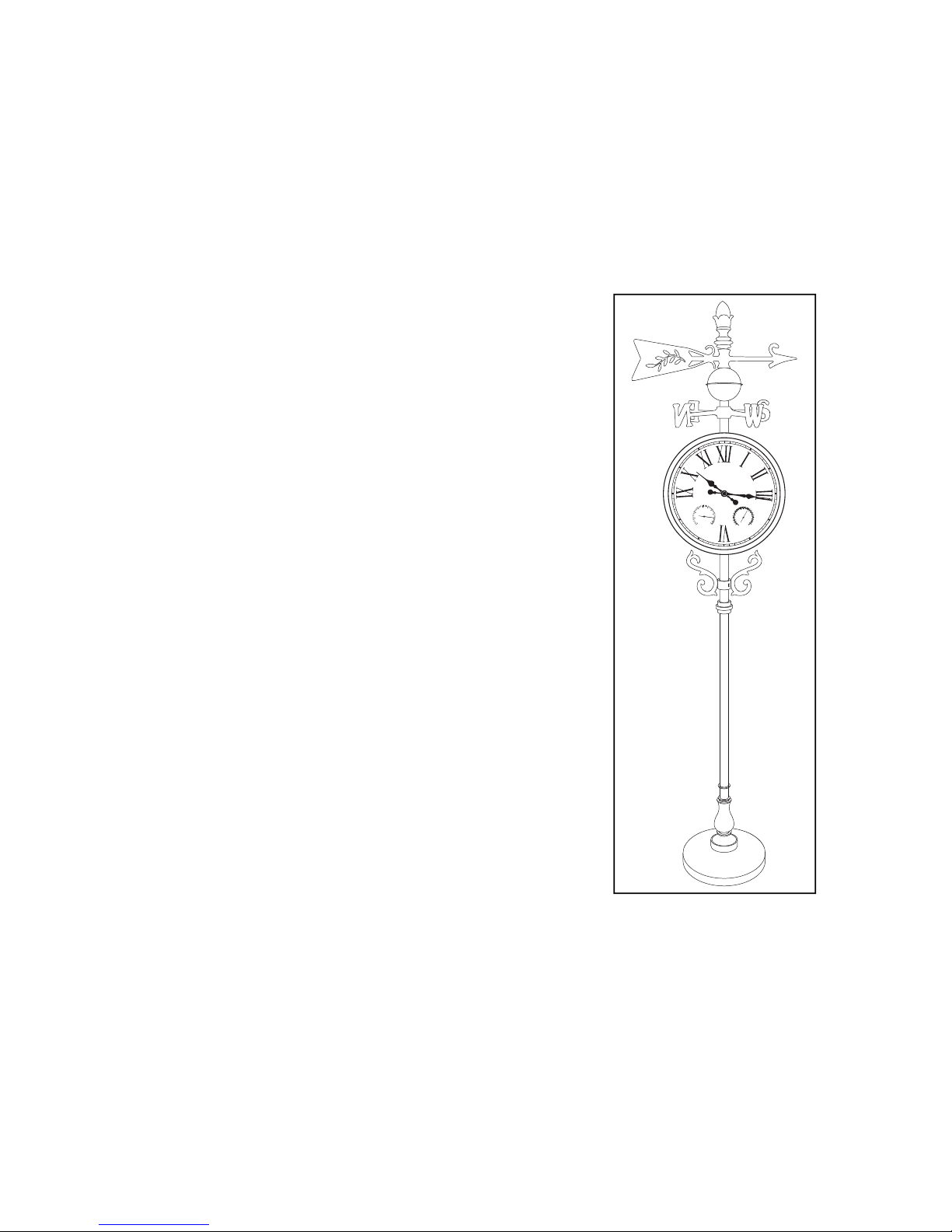
Clock/Weather Station Assembly
Instructions
IMPORTANT! PLEASE READ
All Sunshine garden clocks and weather stations are prepared with a powder coated/
painted nish. The nish will weather over time, depending upon the environmental
conditions where the product is installed. Your proper care of the clock/weather station
(see below) will enhance both its life and appearance. Post treatments, such as clear
lacquer, are not recommended.
PROPER CARE
In order to maximize the appearance of a Sunshine garden clock/weather station, it is
important that dust and debris is removed from its surface periodically. It is recommended that the clock/weather station be wiped down weekly using a soft, dry cloth.
DO NOT use any abrasives such as car wax or other polishes, glass cleaners or chemicals, as this will scratch/remove/damage the protective coating. All Sunshine clocks/
weather stations receive a durable powder coat nish, which enhances their durability. The nish should also be wiped down weekly with a soft, dry cloth to
remove dust and debris that will accumulate on the surface.
FAI LUR E TO F OLL OW T HE A BOV E CAR E I NS TRU CT ION S WIL L IN VAL IDAT E
YO UR PR ODU CT GU AR ANT EE.
REPLACEMENT PARTS
For information regarding replacement parts, please contact your retailer.
GUARANTEE
All Sunshine garden clocks and weather stations are guaranteed against defects in
material and workmanship for a period of ONE YEAR from the date of purchase.
IMPORTANT: This guarantee does not cover damage or failure resulting from accident, misuse or abuse, lack of reasonable care (see above), vandalism, and acts of
nature such as lightning damage. No responsibility is assumed for any special incidental or consequential damages. Damage occuring during transit is not covered by this
guarantee. Any claims under this guarantee should be referred in the rst instance to
your retailer.
TECHNICAL SUPPORT
For advice on installation or technical queries, please contact our Customer Service
Helpline on 0845 456 5111, 9 am - 5 pm Monday to Friday.
Distributed by:
Sunshine Lifestyle Products, Ltd
Unit 9, Oxonian Park
Langford Locks, Kidlington
Oxfordshire, OX5 1FP
TH003 November 2005 Printed In China
HUMIDITY
%
100
90
80
70
60
50
40
30
20
10
0
-40
-30
-20
-10
0
10
20
30
40
50
60
TEMPERATURE
ºC
ºF
-40
-20
0
20
40
60
80
100
120
140
Page 2
Assembly Time:
Time:
20-30 minutes
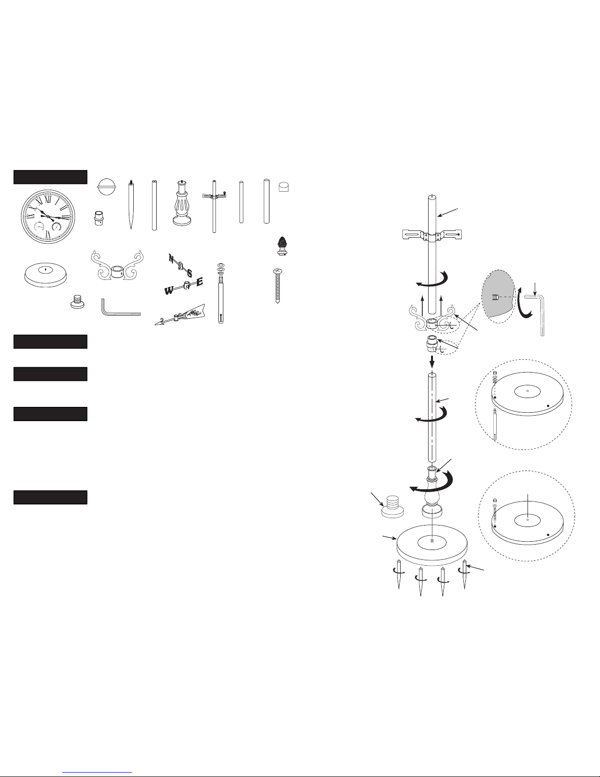
Parts Included:
Usage:
When using this weather station outside, place unit in shaded area away from direct sunlight for
most accurate reading of gauges, as direct sunlight may cause some deviation in gauge readings.
Adjustment:
1) Clock adjustment: The clock is adjusted by the knob clearly marked “CLOCK” on the
back of the gauge.
2) Temperature gauge adjustment: Open the face of the gauge, on the back of the
thermometer side is an adjustment knob, this knob adjusts the temperature setting.
3) Replacing Battery: Insert battery matching the “–” and “+” markings as indicated on the
inside of the battery housing, to the markings located on the battery. Requires 1 “AA”
Battery (Included).
Assembly:
1) Base can be installed with adjustable screw-in foot tabs to stand on hard surfaces, stakes for
insertion into grass/soil surfaces, lag bolts for cement surfaces or wood screws for deck
installation. Thread foot tabs or stakes into the four holes under base. If foot tabs are used,
adjust height as necessary levelling xture for uneven surfaces. If stakes are used, nd level,
rm grass/soil area for inserting stakes. If lag screws are used, insert lag screw and secure
top portion onto base using lock washer, washer and hex nut. If wood screws are used, screw
rmly onto level wood surface. Plug hole where screws were inserted with Hole Cover.
2) Attach decorative bottom to base. Next, attach bottom pole to base.
3) Slide decorative coupler onto bottom pole and slowly slide down to top of Decorative
Bottom. (Do not yet secure).
4) Thread top pole with mounting bracket to bottom pole. (If necessary, adjust height of
bracket by loosening screws and moving bracket to height desired and re-tightening screws.)
Stake (4)
Bottom
Pole (1)
Bottom
Decorative
(1)
Top Pole with
Mounting
Bracket (1)
Thin Pipe
(1)
Large Pipe
(1)
Display Head (1)
Base (1)
Decorative Sleeve (1)
Allen Key (1)
NS Vane (1)
Hex Nut (3)
Washer (3)
Lock Washer (3)
Lag Bolt (3)
Vane (1)
Wood
Screw (3)
Hole
Covers
(3)
Ball (1)
Coupler (1)
Foot Tab (4)
Top Pole
Allen Key
Decorative Sleeve
Coupler
Cement Installation
Wood Deck Installation
Stake
Foot Tab
Decorative
Bottom
Bottom Pole
Base
5) Slide decorative coupler back
up to centre of entire pole, so
it covers the seam between
top and bottom poles.
Using the provided Allen
Key, tighten threaded
nipple embedded inside
coupler until coupler is tight
and secure.
6) Mount display head to pole
by rst sliding one end of
bracket through open-ended
sleeve on back of head. Then
slide head back in
opposite direction, so other
end of bracket slides through
close-end sleeve.
7) Attach decorative bottom to
base. Next attach bottom
pole to base. After display
head is centred on the
brackets, secure display head
to pole by tightly threading
thumbscrews onto bracket.
8) Slide NS Vane (with
imbedded nipple) over top
pole above display head and
secure it to top of pole by
tightening imbedded nipple
with Allen Key. Slide EW
vane over pole, so it rests on
NS Vane.
9) Thread thin pipe onto top
pole and then slide large pipe
over thin pipe.
10) Slide remaining vane and
ball over large pipe.
11)
Slide nial over large pipe
and secure with Allen Key.
EW Vane (1)
Finial (1)
HUMIDITY
%
100
90
80
70
60
50
40
30
20
10
0
-40
-30
-20
-10
0
10
20
30
40
50
60
TEMPERATURE
ºC
ºF
-40
-20
0
20
40
60
80
100
120
140
Page 3

T
e
m
p
H
u
m
i
d
T
e
m
p
H
u
m
i
d
Usage:
When using this weather station outside, place unit in shaded area away from direct sunlight for
most accurate reading of gauges, as direct sunlight may cause some deviation in gauge readings.
Troubleshooting (Adjusting Gauges):
The various gauges contained in this product are calibrated to re ect the current atmospheric condi-
tions present during the time of this productʼs assembly. Vibration during the transportation of this
product may alter the preset readings and accuracy of each gauge. To ensure the proper reading of
each gauge, it is suggested that each unit be checked for accuracy before use. For accurate atmo-
spheric measurements refer to a reliable source such as the newspaper, television, radio, and/or the
internet. If adjustment is necessary, please follow the below instructions for each gauge:
1)
Clock adjustment:
a)
Remove round plastic cap to expose adjustment dial.
b)
To adjust the Clock reading, turn adjustment dial to adjust needle on the face of the unit.
2)
Temperature gauge adjustment:
a)
Remove round plastic cap to expose adjustment dial.
b)
To adjust the Temperature reading, turn adjustment knob marked “Temp” to adjust needle on
the face of the unit.
Note: Temperature gauge accuracy is +/- 2 degrees Celsius or +/-3 degrees Fahrenheit.
3)
Humidity gauge adjustment:
a) To adjust the Humidity reading, turn adjustment knob marked “Humid” to adjust needle on
the face of the unit.
b) It is suggested that adjusting humidity gauge be done every six months.
Note: Humidity gauge accuracy is +/- 5%.
Installing and Replacing AA Battery for Clock
On back of clock, remove round plastic cap by pulling metal ring.
Snap off the battery cover located on the bottom of the clockʼs
gear box.
Insert battery matching the “-” and “+” markings, as
indicated on the inside of the battery housing, to
the markings located on the battery.
Replace battery cover by snapping cover
into place, and re-attach round plastic cap.
M
INCHINA
- AA 1.5V +
MADEINCHINA
- AA 1.5V+
MADEIN CHINA
Remove round plastic cap to
adjust temperature
Adjustable Hole for Clock
Adjustable Knob for
Temperature
Adjustable Knob for
Humidity
Battery Cover
Battery
HUMIDITY
%
100
90
80
70
60
50
40
30
20
10
0
-40
-30
-20
-10
0
10
20
30
40
50
60
TEMPERATURE
ºC
ºF
-40
-20
0
20
40
60
80
100
120
140
HUMIDITY
%
100
90
80
70
60
50
40
30
20
10
0
-40
-30
-20
-10
0
10
20
30
40
50
60
TEMPERATURE
ºC
ºF
-40
-20
0
20
40
60
80
100
120
140
 Loading...