

Page 1
CHARGECONTROLLER CC25000
Operating Instructions
The Sunsei™ CC25000 is a highly reliable charge controller that
is ideal for Sunsei™ SolarChargers up to 25A. It will effi ciently
charge your batteries and provide years of protection from
overcharging. This protective care will prolong your battery life
and reduce maintenance requirements.
PRODUCT FEATURES
IDEAL SOLAR CHARGING
> Compatible – Works with almost all types of batteries
> and solar panels in 12V and 24V confi gurations
> Effi cient – Over 98% effi ciency at full current
> Full Charging – Ensures that the batteries are always
> topped off
> Battery Safe – Charging method maximizes battery life
> Reduced Maintenance – From healthy charging and
> reliable operation
OVER-CHARGE PROTECTION
> High Voltage Limiting – Floats battery at safe voltage
> when battery is full
> Robust Circuitry – Control function 100% solid state
HIGH RELIABILITY
> Simple, rugged electronics – Low component count &
> streamlined design ensure long-term reliability
FEATURES
> Two stage charging – Boost and fl oat charge using pulse
> width modulation (PWM) control
> 12V and 24V systems – Operation for batteries and solar
> panels, automatic voltage detection
> Temperature compensation – Adjusts battery voltage limits
> with temperature
> LED display – Built-in battery voltage and charge function
> indicator by LED display
> Advanced digital control – Uses pulse width modulation
> (PWM) control
> Reverse leakage protection – Prevents power loss at night
> Incorrect Wiring Protection – Reverse battery and solar
> panel protected, surge protection
> Terminal Block – For sound and easy wire connections
1
Array voltage of 50V can only be applied with a 24V battery,
otherwise the unit will be damaged.
2
If the battery is lower than 17V, the charger will recognize it
as a 12V battery.
RELATED SYSTEM EQUIPMENT
The SunseiTM CC25000 is an integral part of a solar electric
power system that includes a solar panel, a battery and a
load.
SOLAR PANELS (“photovoltaic (PV) array”, “solar modules”):
The SunseiTM CC25000 is compatible with all makes and
models of photovoltaic solar panels.
The entire solar array’s open circuit voltage (Voc) cannot
exceed 30V with a 12V battery or 50V with a 24V battery (the
sum of the Voc of all solar panels in series). Also, the solar
array’s peak operating current (Ip) cannot exceed 25A. (This
is the sum of the peak operating currents (Ip) of all the solar
panels in parallel).
Install all panels with the correct series-parallel confi guration
to ensure proper system voltage and current.
The SunseiTM CC25000 circuitry uses a MOSFET transistor to
eliminate leakage of the battery power into the solar panels at
night. No additional protection is needed.
OTHER CHARGING SOURCES: Systems with an additional
source of charging (alternator, battery charger, etc.) can
operate with a solar array and a SunseiTM CC25000. All
charging sources need to connect directly to the battery on
independent lines and have their own form of over-charge
protection.
SunseiTM CC25000 FOR NON-SOLAR APPLICATIONS:
These units will only operate with solar electric panels. Do not
use to regulate other power sources, such as a hydro or wind
generators/alternators or AC battery chargers. These charging
sources can damage the controller and/or the generating
equipment.
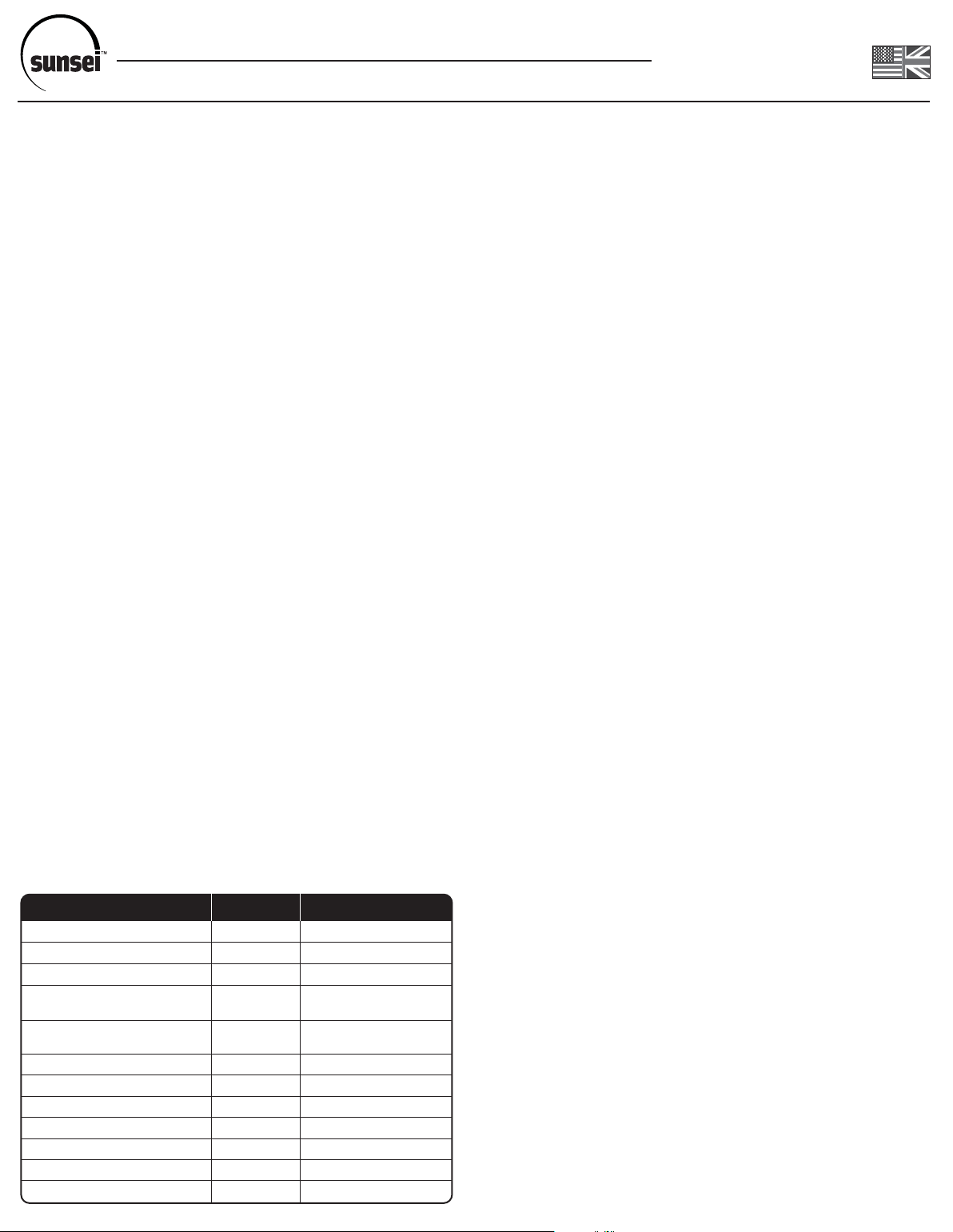
PARAMETERS
Nominal Voltage
Array Voltage, Max (Voc)
Charging Current, Continuous (Ip)
Operating Voltage at Battery,
Min Charging starts at :
Current Consumption
Quiescent (Night)
Boost Charge Voltage (2 hours)
Float Charge Voltage
Regulation Accuracy
Voltage Drop, Array to Battery
Operating Temperature Range
Dimensions
Weight
UNITS
Volts
Volts
Amps
Volts
Milliamps
Volts
Volts
Volts
Volts
ºC (ºF)
inches (mm)
lbs. (kg)
Sunsei™ CC25000
12 or 24
1
30 or 50
25
2
7 or 17
<4
14.5 or 29
13.7 or 27.4
±0.150
< 220 mV
-40 to 50 (-40 to 122)
3.1x3.9x1.25 (80x100x32)
0.40 (0.18)
BATTERIES: The Sunsei
TM
CC25000 provides the proper
charging of standard lead-acid batteries that are normally
used in recreational vehicles, boats and remote stand alone
systems. These include wet cell batteries (with fi ller caps),
sealed, maintenance-free and gel-cell batteries. Automobile
batteries can also be charged, but these batteries are rarely
used as the primary battery in a solar system. Install all batteries
with the correct series-parallel confi guration to ensure proper
system voltage and current.
SYSTEMS WITH TWO BATTERY BANKS: When solar
charging two separate battery banks, a switch can be installed
to allow manual selection of one battery or the other.
BATTERY ISOLATORS: In installations that use a diode
battery isolator with two batteries, the SunseiTM CC25000
needs to connect directly to one of the batteries or an output
from the isolator.
Page 2
CHARGECONTROLLER CC25000
•
Operating Instructions
LOADS: System loads such as lights, radios and DC/AC
inverters must be 12V or 24V DC (unless an inverter is being
used).
INSTALLATION
WARNING: Electricity, even low voltage electricity, can be
dangerous. Installation should be performed by a licensed
electrical contractor or other qualifi ed personnel only.
The requirements of National Electrical Codes should be
followed.
WARNING: Follow all safety precautions of the battery
manufacturer. Proper ventilation must be provided for the
batteries. Most batteries produce hydrogen gas when
charging, which is extremely explosive. Provide adequate
battery ventilation. DO NOT expose the battery to open fl ame,
matches, cigarettes or sparks.
CAUTION: DO NOT EXCEED THE UNIT’S VOLTAGE AND
CURRENT RATINGS
Do not exceed the maximum open circuit voltage (Voc) rating
of 30V for 12V operating systems or 50V for 24V operating
systems. This is the sum of the Voc of all solar panels in
series.
Do not exceed the maximum current rating 25A. This is the
sum of the peak operating current (Ip) of all the solar panels
in parallel.
Do not deviate from the recommended wiring instructions.
2. CONNECT PANELS: If connecting more than one solar
panel, connect the solar panels to the master cable in parallel,
+ to + and - to -.
3. CONTROLLER TO P ANEL CONNECTION: Connect positive
and negative master cable wires to designated positive and
negative terminals of the charge controller.
4. WIRE TYPE: When possible, use stranded wire instead of
solid wire. Stranded wire does not fatigue and cause loose
connections over time as easily as solid wire. Use red wire for
(+) and black for (-).
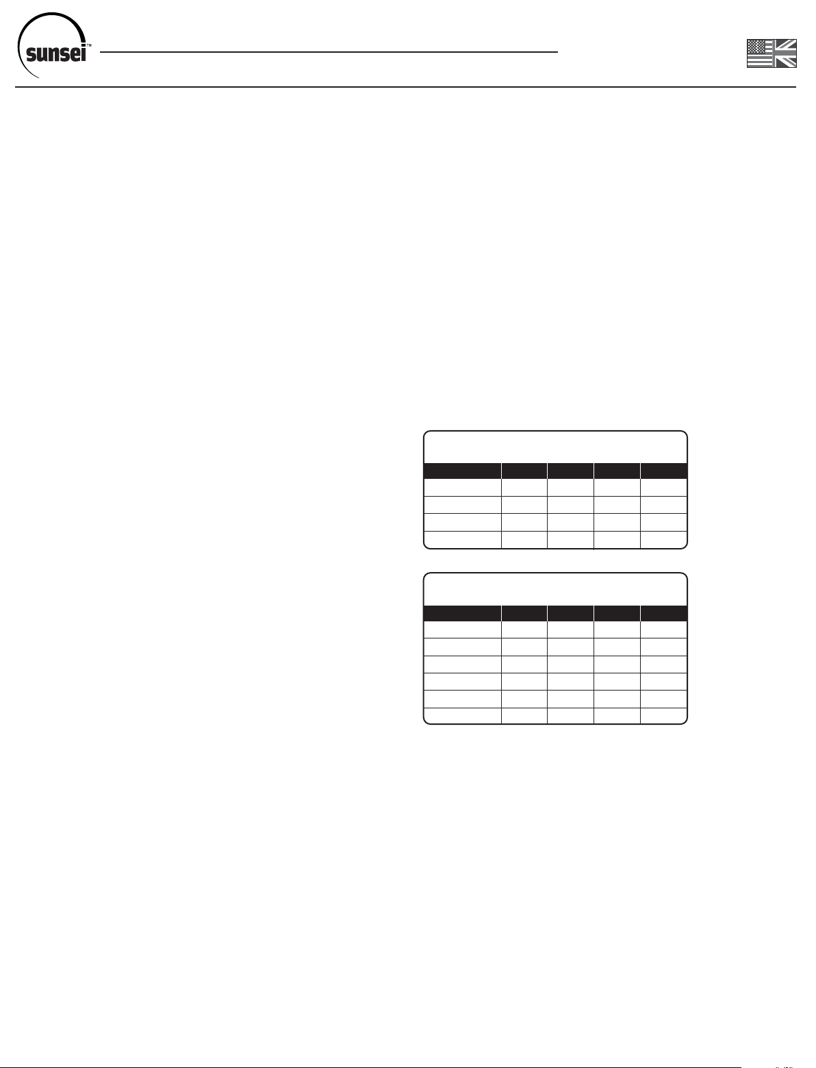
5. WIRE SIZE: Refer to the “WIRE GAUGE” charts below to
determine the minimum size wire needed for each connection.
Note that the bigger the wire, the lower the AWG. When using
large stranded wire, you may need to divide the ends into two
groups and straddle the screw on the terminal block.
RECOMMENDED WIRE GAUGE CHARTS
Recommended Wire Gauge (AWG) Chart to limit voltage drop to 0.3V
Cable Length (ft.)
0 to 5
5 to 10
10 to 15
15 to 20
Charge Controller to Battery
SE-1200
SE-4000
14
14
14
14
14
14
14
12
SE-6000
14
14
12
10
SE-8000
14
12
10
8
INFORMATION
> The charge controller SHOULD NOT BE USED in direct
> sunlight or temperatures exceeding 122ºF (50ºC) or below
> -40ºF (-40ºC). It should be installed within 5 feet (1.5m)
> of the battery in a cool, dry and well ventilated area.
> Intended for indoor use.
> DO NOT USE MORE THAN 25A (400W for 12V or 800W
> for 24V) of solar power with the Sunsei™ CC25000.
> ALL connections should be in PARALLEL (Positive to
> Positive, Negative to Negative). Ensure that connections
> are clean and solid.
> Always CONNECT the BATTERY FIRST, and
> DISCONNECT
> connecting a fuse close to the battery on wires extending
> from it, especially for longer runs. Follow electrical codes
> where applicable.
> For all additions or longer distances, use up to #6
> (gauge) wires. Always CONNECT the BATTERY FIRST,
> and DISCONNECT the BATTERY LAST.
the BATTERY LAST. It is recommended
PROCEDURE
Mount charger on a dry non-fl ammable surface. Use mounting
holes.
1. CONTROLLER TO BATTERY CONNECTION: Connect
positive and negative wires into designated positive and
negative terminals of the controller. Then carefully connect
wires to battery and/or fuse terminal (see wire selection table
below).
Recommended Wire Gauge (AWG) Chart to limit voltage drop to 0.5V
Cable Length (ft.)
0 to 10
10 to 20
20 to 30
30 to 40
40 to 50
50 to 60
Panel to Charge Controller
SE-1200
SE-4000
14
14
14
14
14
12
14
14
12
12
10
10
SE-6000
14
12
10
10
8
8
SE-8000
14
12
10
8
8
6
6. COMPLETE THE INSTALLATION OF PANELS, BATTERY
AND LOAD
LOCATION
The SunseiTM CC25000 should be mounted where it can be
easily seen and reached as needed. Carefully consider how
the wires are to be run from the solar panel to the controller
and from the controller to the battery. The SunseiTM CC25000
should be mounted as close to the battery as possible to
reduce voltage drop in the wires. Wires extending from the
battery should be fused. Respect local electrical codes where
applicable.
Page 3
CHARGECONTROLLER CC25000
Operating Instructions
OPERATION
The operation of the Sunsei
TM
CC25000 is completelyautomatic.
This controller will regulate the charging of batteries during
conditions of heavy usage, or when left unattended for long
periods of time.
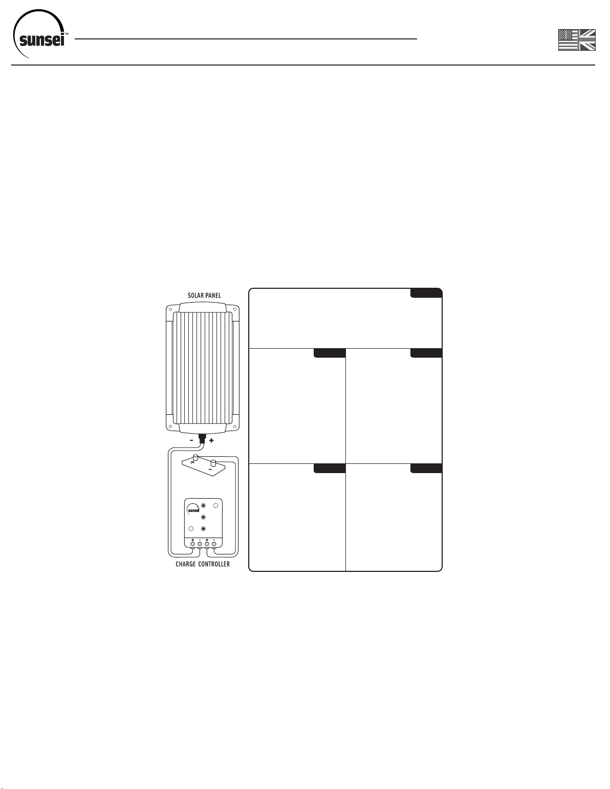
CHARGING ST A TUS LIGHTS: There are three (3) LED status
lights that indicate the charging status of the CC25000:
Red = low battery indicator, Yellow = good battery voltage
indicator, Green = charging status.
HOW TO READ THE LIGHTS:
NOTE: Double the values for 24V systems.
1) All LED lights off: Insuffi cient voltage from solar panel and
battery to activate the controller.
2) Green “Charging” LED
lit constant: Solar panel is
charging the battery. When
battery voltage falls goes
below 12.5V, the charger will
> Contrôleur de charge intelligent
garanti à la batterie une
puissance de charge maximale
> Indicateur LED intégré
affiche instantanément l’état
de la charge
charge the battery in boost
mode up to 14.5V maintaining
for two hours and then go into
fl oat mode of 13.7V using
PWM.
3) Green “Charging” LED
fl ashing: Charger is in PWM
mode either in boost mode or
fl oat mode which means that
the battery is being topped off
or full.
4) Yellow LED on: Yellow LED
is a battery state of charge
indicator based on voltage,
day or night. LED “On” means
the battery is 12V or above;
“Off” means the battery is
below 12V. The yellow LED
> Control de carga inteligente
Asegura potencia de batería máxima
> Indicador a diodo LED integral
Indica estado de carga
inmediatemente
> Conectores a tornillo incorporados
Para una instalación rápida y sencilla
> Interruptor de circuito a rearma
automático
Para inversión de polaridad y
protección contra picos de voltaje
> Intelligente Aufladung Steuerung
stellt maximale Batterieleistung sicher
> Eingebaute LED Anzeige
zeigt sofort aufladenstatus an
> Integrierte Schraube
Anschlußanschlüsse
für schnelle und einfache Installation
> Automatische-reset Schutzschalter
für Rückpolarität und Schwankung
Schutz
works in conjunction with the
red LED, so when the yellow
LED turns off, the red LED turns on and vice-versa.
5) Red “Low battery” LED lit constant: Battery is very low
voltage, between 11.5V and 12V. Load must be reduced.
WHAT TO CHECK: Check to confi rm all wire connections are
sound and free from corrosion. Tighten terminal particularly at
the battery. Also, consider checking for a voltage drop in the
cables which should be less than 0.5V between the
solar panel and the controller and less than 0.3V between the
controller and the battery.
MAINTENANCE
RECOMMENDED CARE: Any solar system, when designed
correctly, should provide years of reliable charging with very
little user involvement. To assure system reliability, a regular
routine of checking the electrical connections is recommended.
Especially on a moving vehicle exposed to road vibrations.
Over time, electrical connections can deteriorate or corrode
causing a voltage drop and possible hot-spots at the problem
area.
FRANÇAIS
> Connexions intégrées
facilitent l’installation
> Limiteur de charge
évite les surcharges et
les inversions de polarité
ITALIANOESPAÑOL
> Controllo di carica intelligente
assicura la massima potenza della
batteria
> Indicatore a LED incorporato
visualizza lo stato di carica istante
per istante
> Connettori a vite integrati
per un’installazione facile e rapida
> Interruttore automatico di protezione
per inversioni di polarità e
sovraccarichi
DEUTSCH NEDERLANDS
> Doordachte laadcontrole
garandeert maximaal accuvermogen
> Ingebouwde LED-indicator
toont continue de laadstatus
> Geïntegreerde schroefaansluitingen
voor snelle en makkelijke installatie
> “Auto-reset” stroomonderbreker
t.b.v. ompool- en vermogens
schommelingbeveiligin
g
TROUBLESHOOTING
These sections can assist
in the troubleshooting of a
solar system. If a problem
is suspected, please verify
all components (solar panel,
battery and controller).
SOLAR PANEL
To verify the solar panel,
disconnect it from the controller.
In full sun, it should give its
rated open circuit voltage (Voc).
Measure across the two wires
extending from the solar panels
with a DC voltmeter. Then
measure the output current by
connecting the panel directly
to the battery. Put the DC
ampmeter in one of the lines
and verify that the panel can
put out its rated current (in full
sun).
BATTERY
With the panel connected to the battery as above, the battery
voltage should be within the maximum values indicated by the
manufacturer.
6) Red “Low battery” LED fl ashing: Battery has extremely low
voltage, below 1 1.5V. Load must be disconnected and battery
allowed to recharge.
A TYPICAL DAY: A typical daily cycle will be as follows. As the
charging starts for the day and battery state of charge is low,
charging will be continuous and the “CHARGING” light will be
on all the time. Battery will be charged up to 14.5V or 29V,
the Boost voltage, and kept at this level for two hours using
PWM control. Then, the controller goes into fl oat mode and
will maintain the battery at 13.7V or 27.4V indefi nitely as long
as the load current does not surpass the charging current.
CHARGE CONTROLLER
Reconnect the working panel and good battery and the charge
controller should turn on as indicated by the charging LED
lighting up.
Page 4

CHARGECONTROLLER CC25000
Operating Instructions
WARRANTY
ICP Solar Technologies grants the original purchaser of the
Sunsei™ CC25000 Charge Controller a 2-year warranty
against any defects of materials or workmanship. This warrant
not be responsible for any costs due to removal, shipment,
re-installation or any other loss due to warranty servicing. The
maximum liability to ICP under this warranty shall not exceed
the purchase price of this controller. This warranty does not
cover a controller that has been damaged by misuse, neglect
or improper installation. ICP shall not be responsible for any
damage to persons or property caused by improper installation,
misuse or improper handling of this product. Some states do
not allow exclusion or limitation of accidental or consequential
losses so the exclusions may not apply to the purchase.
This warranty gives you specifi c legal rights and you may
have other rights, which vary from one state (or province) to
another. Please note that ICP will not accept returns without
prior authorization. The original proof of purchase is required
for warranty validation.
 Loading...