

Page 1
Solar Energy Technologies
Installation, Operation &
Maintenance Manual
150 Litre
Indirect
Flat Plate
Thermo-syphon Solar System
Page 2

SunScan™ Technologies
- 1 -
Contents
1. Introduction…………………...……………………………………………….………….…2
2. System description……………………………………………………………………….…3
2.1 How the system works……………………………………………………………..3
2.2 Thermal performance……………………………………………………………...3
2.3 Orientation and placement……………………………………………….....……..4
2.4 Freeze protection……………………………………………………………...……4
2.5 Hail resistance……………………………………………………………………....4
2.6 Scale resistance…………………………………………………………………….4
3. Safety precautions…………………………………………………………………………..5
3.1 General safety information…………………………………………………….......5
3.2 Safety considerations for installation and operation……………………..……..5
4. Installation…………………………………………………………………………………….6
4.1 System components……………………………………………………………..….6
4.2 Important considerations and good practice………………………………….….7
4.3 Flat roof stand assembly and installation………………………………….……..8
4.4 Storage tank………………………………………………………………………...12
4.5 Mounting the collector……………………………………………………………..13
4.6 Plumbing installation……………………………………………………………....14
4.7 Adding the heat transfer fluid..………..…………………………………………..15
4.8 Electrical installation...………………………………………………………….….15
4.9 Commissioning…….....………………………………………………………….....15
4.10 Check list…………………………………………………………………………….16
5. Operating instructions……………………………………………………………………....15
5.1 Start up procedure….……………………………………………………………....15
5.2 Emergency shutdown procedure..…………………………………………….….16
5.3 System performance..………………………………………………………….…..16
5.4 High water temperatures…………………………………………………………..17
6. Maintenance………………………………………………………………………………....17
6.1 Routine maintenance……………………………………………………………....17
6.2 Trouble shooting…………………………………………………………………....18
7. Technical specification…………………………………………………………………….. 19
8. Warranty………………………………………………………………………………………21
9. Sign off (customer copy)…………………………………………………………………….22
10. Sign off (Installer copy)………………………………………………………………………23
Liability waiver
Page 3

SunScan™ Technologies
- 2 -
This manual must be read in conjunction with the geyser manual as well as any additional depictions or
instructions pertaining to any valves and installation thereof.
SunScan reserves the right to update this manual without prior notice. It is the installer’s responsibility to
ensure that the latest version of this manual is being used. The installation and maintenance of all SunScan
thermal solar systems are to be carried out by trained and qualified personnel only.
SunScan may not be held liable for any damages to property nor injury or death that may result from the use
of their product.
1. Introduction
Congratulations on purchasing a SunScan solar water heating system, all of our collectors use cutting edge
technology and attractive design to bring you a high quality product.
This manual must be read thoroughly and understood before undertaking to install any of the SunScan range
of products, please note that this manual is specific to the system or systems that appear on the cover page, If
after reading this manual any aspect of the installation process remains unclear contact a SunScan
representative prior to installation.
This manual serves only as a guide to the correct installation of SunScan components; it does not seek to
defy logic and or the experience of suitably trained installers, use discretion.
SunScan Solar water heating components must be installed in compliance with the following regulations:
SANS 198
SANS 10252 -1
SANS 10254
SANS 10106
SANS 60335-2-21
SANS 10400 – parts A, B, L, XA
SANS 10142-1
No modifications from these standards are allowed.
All local bylaws and estate laws must also be adhered to.
Failure to comply with any or all of these standards may result in injury or death and may void the warranty.
Any attachment, connection, integration or general association of parts or components that directly or indirectly
affect the operation or performance of a SunScan product could void the warranty. Such parts not supplied by
SunScan must be authorised by SunScan in writing in order to retain the benefits of the warranty.
SunScan does not accept responsibility for the final fitness of the water for consumption, as the water quality
is not affected by the system.
Page 4
SunScan™ Technologies
- 3 -
MODEL
Q-FACTOR
ENERGY RATING
150L SunStream Indirect
16.7mj
2. System description
2.1 How the system works
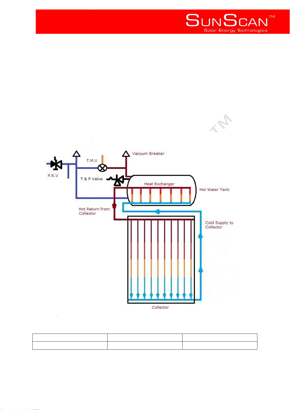
SunScan’s SunStream indirect systems rely on a thermosyphon principle to move heat transfer fluid
heated by the sun via a SunScan flat plate collector to a heat exchanger located in the hot water tank above
the collector,
As the heat transfer fluid in the collector is heated it becomes lighter and rises to the highest point (Heat
exchanger in the Hot water storage tank), heat from the heat exchanger is then transferred to the water intended
for use, at no point does the heat transfer fluid come into contact with the water intended for use, hence indirect.
The heat transfer fluid used in a SunScan Sunstream indirect system is a non toxic food grade glycol
solution.
2.2 Thermal performance
Page 5
SunScan™ Technologies
- 4 -
The technical data above has been verified and confirmed by tests conducted by the South African Bureau of
Standards in terms of SANS 6211, at an incoming radiation of 20MJ per m² per day, a temperature differential
of10°C at an inclination of latitude plus 10°.
2.3 Orientation and placement
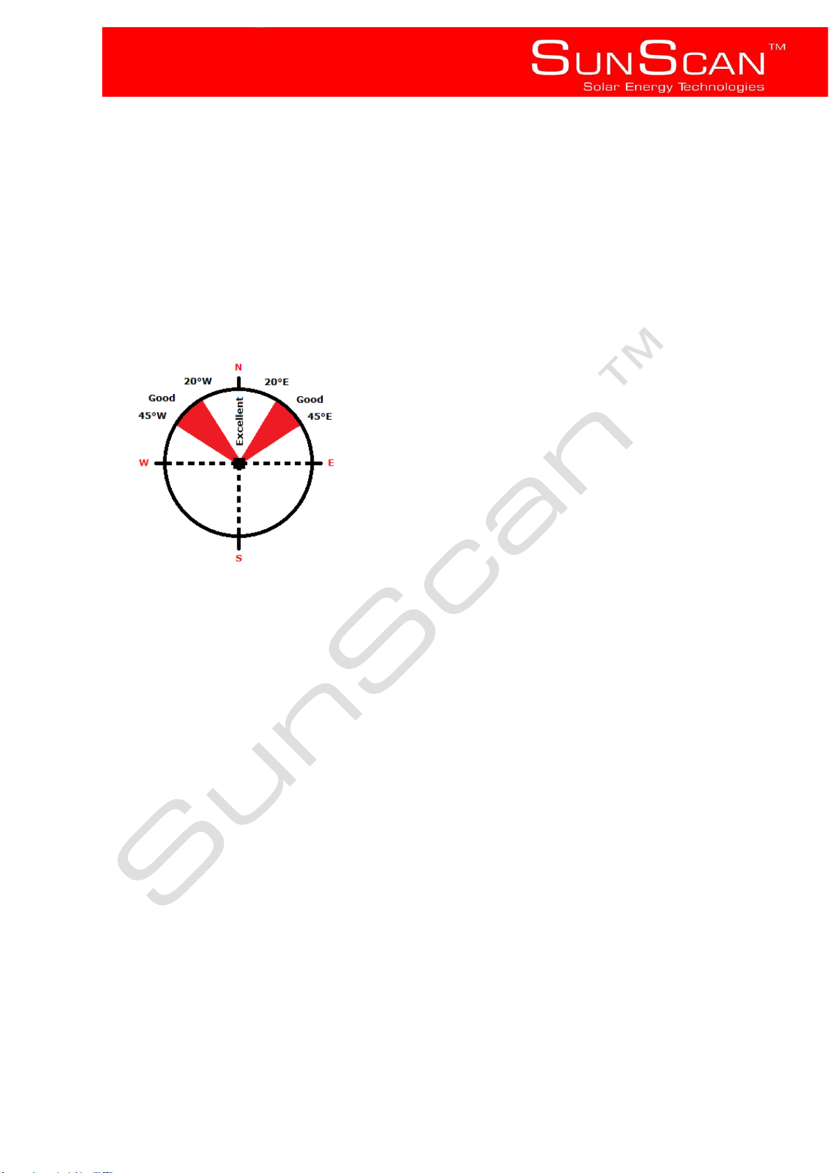
North-facing (true North) is optimal when installing in the southern hemisphere, however deviations of up to 45°
either side of North would be acceptable with very little effect on system performance, SunScan does not
recommend the installation exceed the 45° range either side of North, however some exceptions may be made
when 45° off North cannot be achieved. Contact a SunScan Representative for a rational design.
The collector should be mounted in an all year round shade-free area, or an area that does not shade between
the hours of 9:00am – 15:00pm.
Take care to ensure the roof area chosen for installation is structurally sound and capable of bearing additional
weight. Consult a trained professional if required, if the roof or structure is found unfit to carry additional load, do
not install the system unless the roof can be sufficiently strengthened.
2.4 Freeze protection
The SunScan SunStream indirect system is suitable for areas that experience frost and temperatures
below 0°C as the heat transfer fluid has anti-freeze properties.
2.5 Hail resistance
SunScan flat plate collectors are hail resistant with 3mm tempered glass, they can withstand hailstones of up
to 35mm in diameter.
2.6 Scale resistance
The SunScan SunStream 150L indirect system is suitable for areas with ‘poor water quality’ as the
collector and internals of the heat exchanger transport a scale resistant heat transfer fluid, however care should
always be taken to ensure that scale and mineral deposits do not affect the longevity of your SunScan indirect
system, if you are unsure as to the water quality in your area consult your local municipality.
Generally, water quality is acceptable when it contains less than 600 parts per million total dissolved solids.
Page 6

SunScan™ Technologies
- 5 -
A mildly acidic solution, e.g. vinegar can be used to flush the tank and loosen any scale deposits that might occur
on the outside of the heat exchanger. Consult a trained professional or installer in this regard.
3 Safety precautions
3.1 General safety information
• WARNING! This appliance is capable of producing temperatures that exceed 50°C.
In certain circumstances safety valves could open to expel hot water and relieve pressure,
Never obstruct these valves and always leave them open to the atmosphere.
• This apparatus is intended for water heating only.
• Any and all work carried out in regards to the installation, commissioning and maintenance
of any SunScan Solar water heating system in its entirety is to be carried out by qualified and suitably
trained professionals.
3.2 Safety considerations for installation and operation
All installations are to be carried out in accordance with the Occupational Health and Safety Act (Act 85 of 1993)
requirements and any relevant local authority prescriptions.
General points to consider:
• Assess site specific risks and mitigate to an acceptable level prior to installation, if required consult a trained
professional.
• Water temperature can reach boiling point and collectors can stagnate at temperatures that exceed 150°C.
Cover collectors during installation to prevent heating, and limit the risk of scalding.
• Be aware of any overhead power lines outside and electrical wiring inside the ceiling space.
• Handle collectors and hot water tanks with care to prevent glass breakage, damage to property and personal
injury.
• All safety gear must be worn at all times where relevant; these include but are not limited to safety goggles,
gloves, hard hats and safety shoes.
• Ensure installation personnel are competent and in suitable physical condition.
• Any scaffolding or specialized safety equipment must be installed by certified personnel.
• Installers must be trained and conversant with the assessment of height hazards, safety procedures at heights
and relevant safety equipment.
• All personnel working on the installation of a solar water heating system must be issued with the appropriate
safety equipment.
• Ensure that occupants are aware of all health and safety implications relevant to them.
• Do not attempt to install a solar water heating system if weather conditions are not suitable i.e. high winds,
rain and lightning, etc.
Page 7
SunScan™ Technologies
- 6 -
4. Installation
4.1. System components
Main Components:
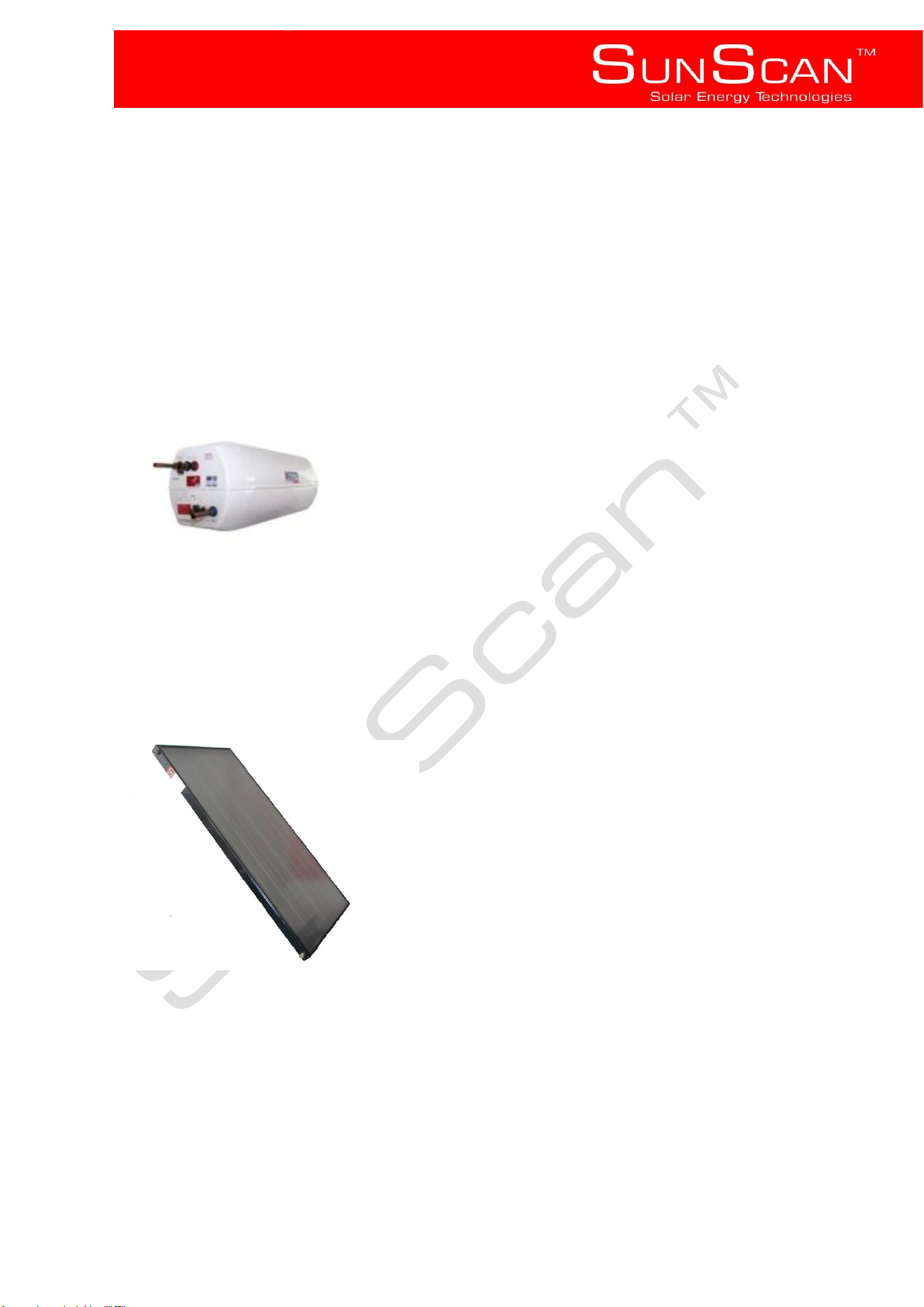
1 x Storage tank
1 x Flat plate collector
2 x 5L Heat transfer fluid
• Storage tank
The storage tank is made from a High tech epoxy vinyl ester composite, there are two 22mm copper tubes
protruding (these are connected to the heat exchanger inside the tank) top - Hot return from the collector (red),
bottom – cold supply to the collector (blue), there is a compression type fitting (red) for the hot out (to points of
use), a drain cock for connecting the cold water in (blue), and a pre-fitted Temperature & pressure relief valve.
• Flat plate collector
The SunScan 2m² Flat plate collectors are manufactured from high quality materials which consist of:
• 3mm low iron, refractive and tempered safety glass
• 0.5mm Aluminium complex anodised selective coated absorber
• Copper headers and riser tubes
• 35mm glass wool insulation
• Profiled aluminium ‘smart design’ casing
• There are four 22mm connection points
Page 8
SunScan™ Technologies
- 7 -
• Heat transfer fluid
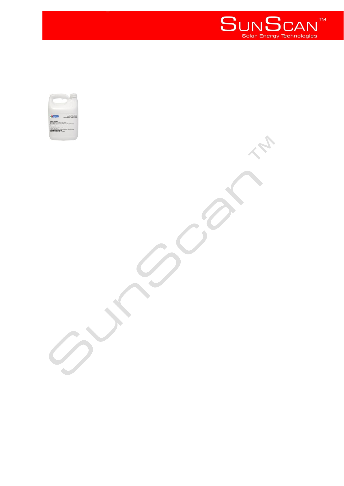
The heat transfer fluid is a pre – mixed non toxic food grade glycol solution.
Additional Components include:
• 1 x Thermostatic mixing valve
• 1 x Flat roof stand (On request)
Components not supplied may include any and all relevant plumbing and electrical components required but not
listed above, i.e. Pressure reducing valves, capillary fittings, Copper tubing, electrical cable etc.
4.2 Important considerations and good practice
• All plumbing must conform to the relevant governing bodies, ensure that the storage tank and collector
installation complies with SANS 10254 and SANS 10106.
• Only compression fittings should be used on the collector and tank, for the rest of the circulation loop high
temperature solder may be used.
• All Brass fittings and or valves, safety or otherwise will be DZR rated, and approved for use by SABS.
• All pipe work to and from the collector must be copper (Class 1 minimum).
• All pipe work to and from the collector, and any pipe/s transporting hot water are to be insulated, insulation will
be heat tolerant and UV resistant.
• SABS approved plastic piping may only be used inside the building, downstream from the thermostatic mixing
valve.
• The thermostatic mixing valve provided must be installed to ensure safe use of the system, and should be
accessible for maintenance purposes.
• During installation ensure no debris e.g. Metal filings, packaging residue, saw dust etc. enters the system, if this
does occur flush the system prior to filling.
• Cover collectors while installing the pipe work to prevent stagnation and possible scalding.
• Exercise caution while lifting and installing the collector and or tank onto the roof, ensure that there are enough
personnel present to bear the weight and that there are adequate lifting tethers and safety rigging as required.
• If the tank is to be installed in the roof space, ensure an adequate structure that complies and does not conflict
with SANS 10400 – L has been erected.
Page 9
SunScan™ Technologies
- 8 -
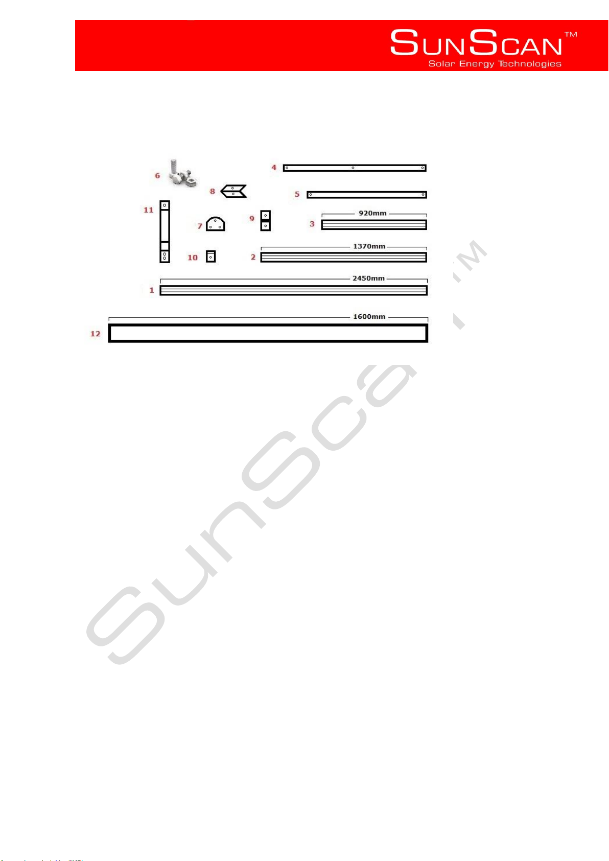
4.3 Flat roof stand assembly and installation
A combination of powder coated aluminium and powder coated Marine grade stainless steel make up SunScan’s
adjustable Flat roof stand.
1 – 2 x Side supports (Aluminium)
2 – 2 x Vertical supports (Aluminium)
3 – 2 x Cross supports (Aluminium)
4 – 2 x back cross braces (Aluminium)
5 – 2 x Side braces (Aluminium)
6 – 8mm Stainless Steel Nuts and Bolts (316 SAE Marine grade)
7– 2 x Side angle plates (316 SAE Marine grade)
8 – 4 x Foot plates (316 SAE Marine grade)
9 – 4 x Corner brackets (Aluminium)
10 – 4 x securing clips (316 SAE Marine grade)
11 – 2 x Cradles
12 – 1 x Load support
Page 10
SunScan™ Technologies
- 9 -
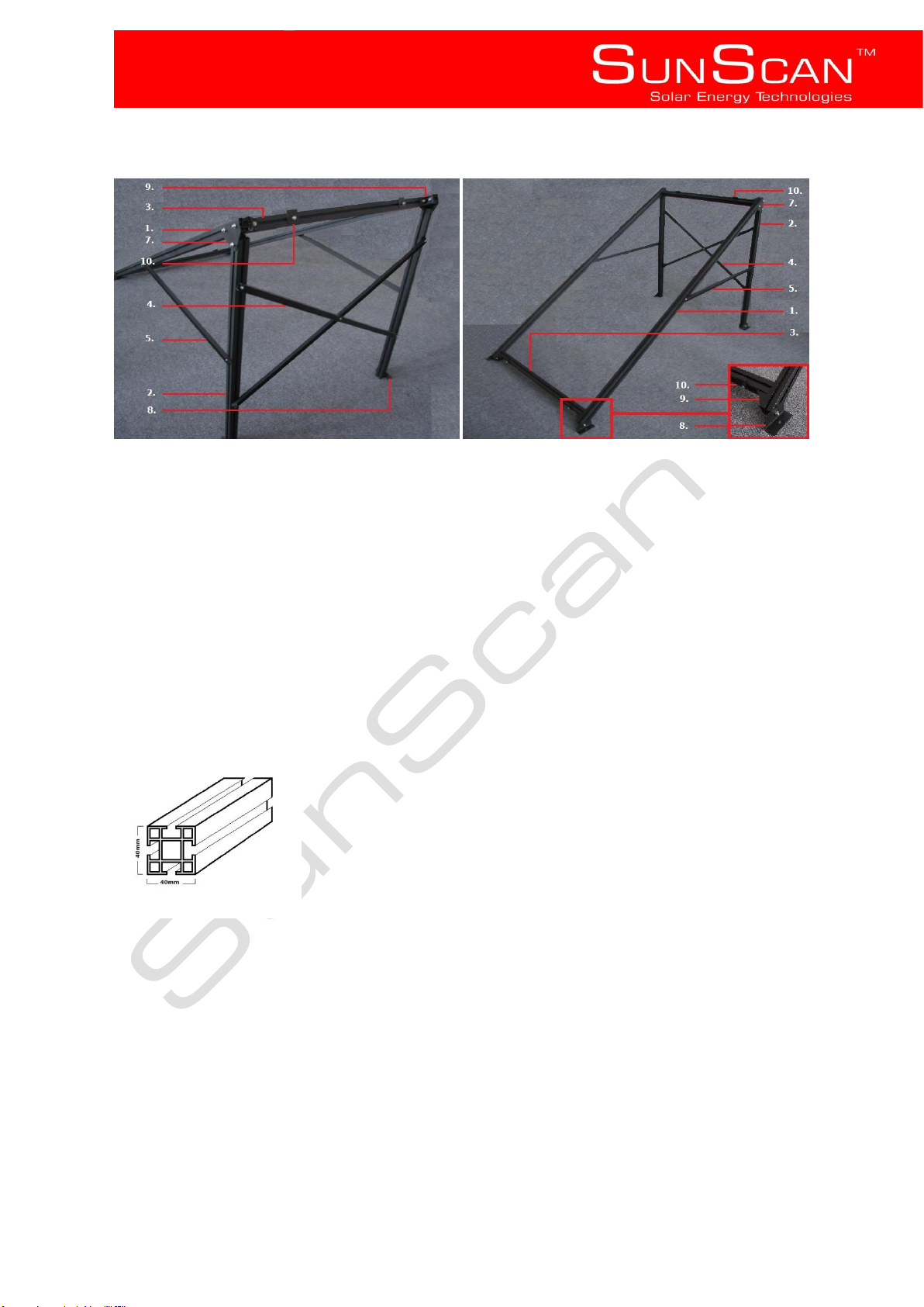
The standard vertical support is 1370mm, however upon request, if required, longer or shorter vertical
supports may be provided in order to obtain the optimum inclination or tilt angle.
Inclination and tilt angle
The optimum angle is equal to the latitude of the location plus 10°.i.e. a location with latitude of 25° would
indicate an optimum inclination of 35°, 15° either side of these figures will make very little difference in terms of
performance.
Please note that a min 20° and max 50° tilt angle must be respected at all times.
Assembly
• Note:
• SunScan’s unique powder coated aluminium profiled channel allows for easy assembly, slide the 13mm
head of the 8mm bolts provided into the channel to assemble components.
• SunScan’s flat roof stand vertical supports are supplied in various lengths to aid in tilt and inclination
angles
Step 1
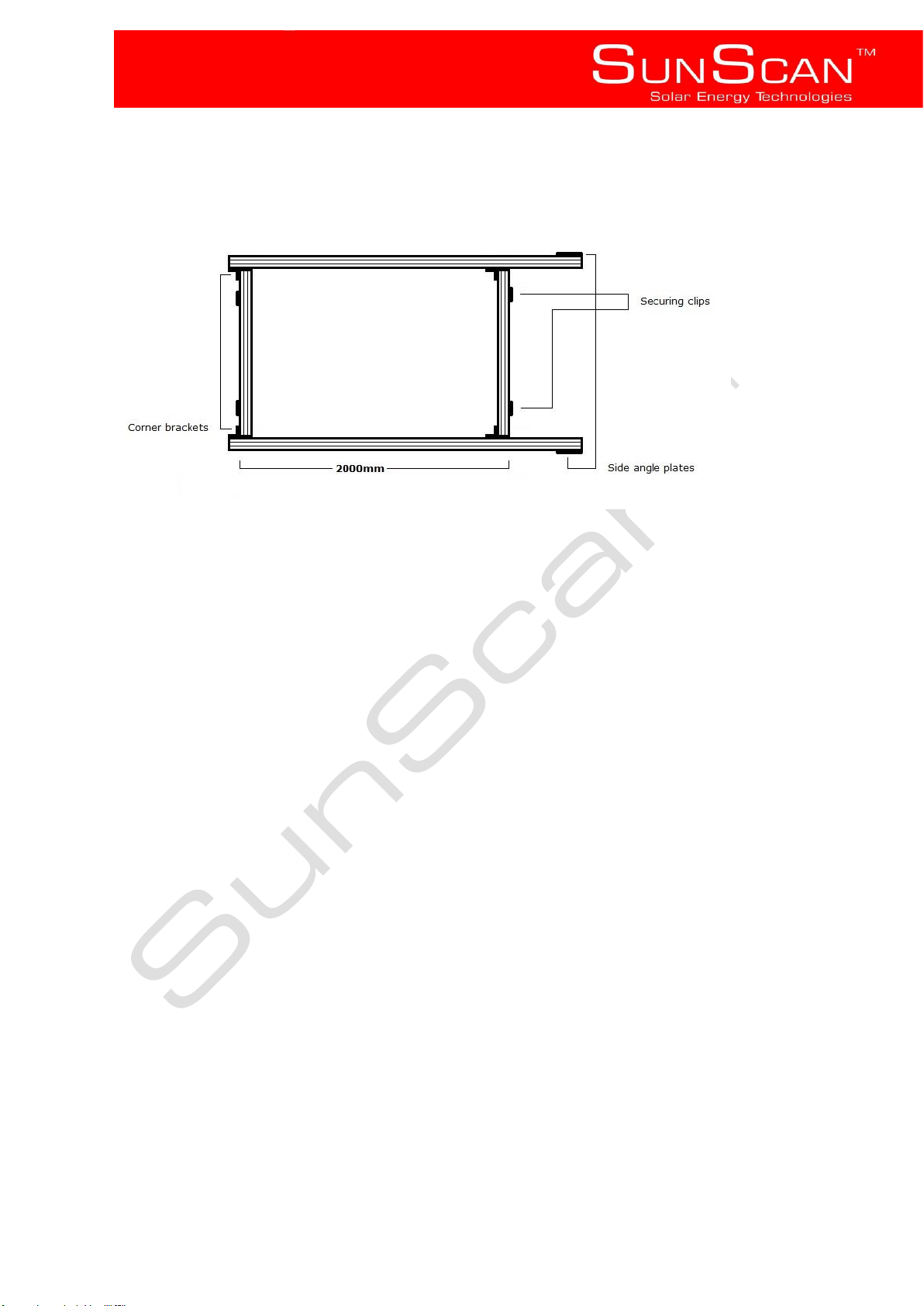
Lay the two side supports (1) on a flat area roughly 1m apart, insert the two cross supports (3) at either end and
between the side supports, place 2 bolts in the channel of each cross support that faces outward and attach two
securing clips (10), using corner brackets (9) and nuts and bolts (6) secure the cross supports to the side
Page 11
SunScan™ Technologies
- 10 -
supports, ensure that the distance between the two cross supports measure 2000mm (outside measurement).
Step 2
Using nuts and bolts attach the two side angle plates (7) (one of each) to either side of the two side supports then
attach a vertical support (2) to the side angle plate on either side.
Step 3
Using nuts and bolts attach each side brace to the vertical and side supports.
Step 4
Using a bolt through the centre holes attach the two back cross braces (4) together, attach the back cross
bracing to the vertical supports. Attach a foot plate (8) to the end of each vertical support; attach a foot plate to
the bottom end of each side support.
Step 5
Flip the structure 180° so that the foot plates are on the flat area.
Step 6
Adjust the inclination by loosening the side angle plates on the side supports and carefully sliding the vertical
supports up or down the side supports, once a suitable tilt angle has been acquired make sure that all the nuts
and bolts have been securely tightened.
Step 7
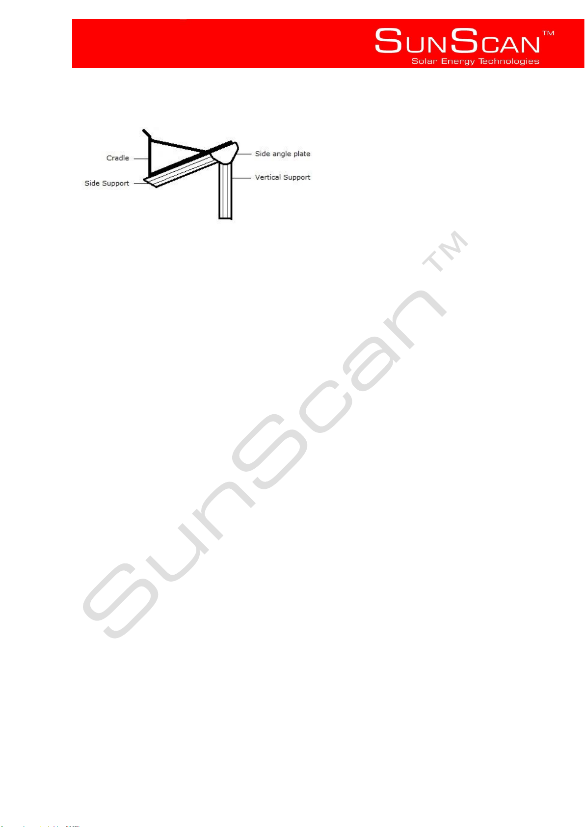
Attach two cradles (11), one to either side of each of the side supports.
Page 12
SunScan™ Technologies
- 11 -
Installation
Always ensure that materials used to fasten the collector and or frame to the roof do not accelerate corrosion,
and that no galvanic action occurs, if required U.V. resistant insulators must be used.
Step 1
Lift the assembled frame onto the roof carefully using tethers and rigging as required.
Step 2
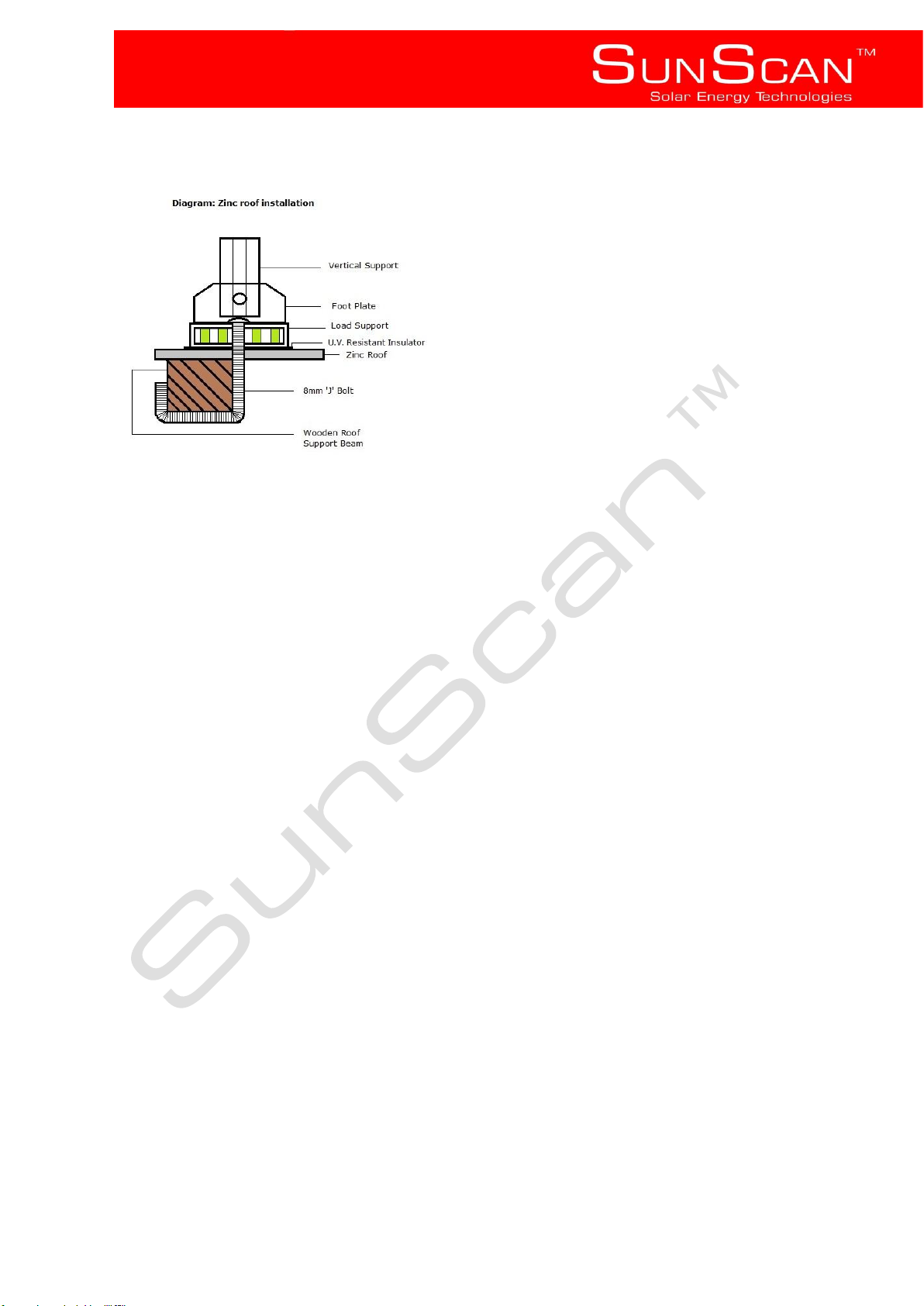
In the case of a zinc roof SunScan recommends that a minimum of 4 x 8mm ‘J’ Bolts are used to secure the
flat roof stand, place the stand in the intended position, making sure to line up with the existing timber structure
inside the ceiling space, if this is not possible additional timber support beams may be required, also ensure that
these structures have been assessed and can bear the additional weight.
Step 3
Place the load support under the two rear foot plates, using the foot plates and a pencil, mark out where the four
8mm holes (for ‘J’ Bolts) are to be drilled, remove the stand and drill the holes.
Step 4
Place the stand and foot plates over the holes and insert the U.V. resistant insulator, from inside the roof space
thread the ‘J’ Bolts through the holes, ensure that there are at least two personnel to achieve this goal, secure a
nut to the end of the ‘J’ Bolt and tighten, repeat this process for all four foot plates.
Page 13
SunScan™ Technologies
- 12 -
Step 5
Waterproofing
Ensure that any holes or modifications to any roofing are adequately waterproofed.
SunScan recommends a UV resistant sealant.
4.4 Storage tank
• Note: Before installing or maintaining any plumbing or electrical component ensure that any water and or
electricity supplied to the component is shut off upstream from where the intended work is to be carried out.
SunScan’s 150L SunStream Indirect system is designed to operate at a working pressure of 400kpa, a
pressure reducing valve with a rating not exceeding 400kpa must be installed.
Mounting to a SunScan flat roof stand:
Step 1
Place the hot water tank into the two cradles, using two stainless steel straps and nuts and bolts, on either end of
the tank tension the straps around the tank and secure to the cradles using the machined sections in the centre
of each cradle as a fastening point.
In Roof:
Ensure that a suitable structure has been constructed inside the ceiling space and that supports to bear
additional weight comply with SANS 10400 pt L, also take note of SABS0163, SABS 0400-1990 Part L and
SANS 10106 5.3.3
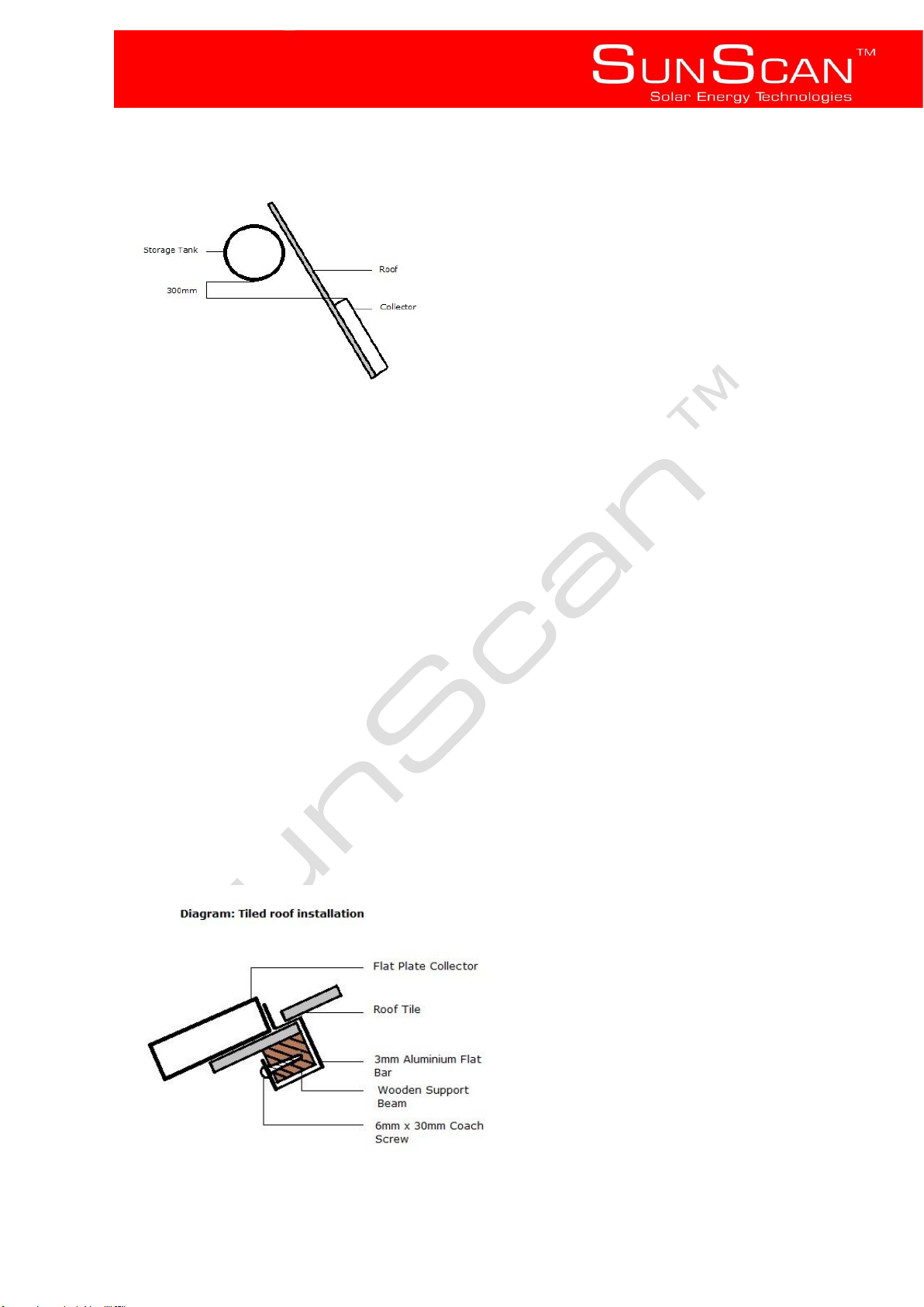
Ensure that the bottom of the Hot water tank is positioned at least 300mm above the top of the intended position
of the collector.
Page 14
SunScan™ Technologies
- 13 -
4.5 Mounting the collector
Ensure that the thermal probe pocket located on the top left corner of the collector is always installed at the
highest point, and that the collector is installed the right side up.
Mounting to a SunScan flat roof stand:
Step 1
Mount the collector to the flat roof stand using the 4 securing clips provided, allow the two securing clips located
on the bottom cross support to slot into the aluminium profile of the flat plate collector, attach two securing clips
to the top cross support and repeat process, tighten the nuts to ensure the collector is fastened to the stand.
Typical flush mounting:
Step 1
Using aluminium flat bar (4 of40mm x 300mm x 3mm), drill an 8mm hole into one end of the flat bar and attach
to the collector turning a 8mm bolt into the riv-nuts located on the collector (2 x top, 2 x bottom), slip the flat bar
under the roof tile, bend the flat bar to fit the roofing profile. Use a coach or wood screw (minimum of 6mm x
30mm) to fasten the flat bar to the wooden support beam, repeat this process (top and bottom) until all four points
are secured.
Page 15
SunScan™ Technologies
- 14 -
Waterproofing
Ensure that any holes or modifications to any roofing are adequately waterproofed.
SunScan recommends a UV resistant sealant.
4.6 Plumbing Installation
Note: When tightening compression fittings, use one spanner to hold the weld nut and another to tighten the
compression nut. Do not grip any pipe work and take care not to over tighten.
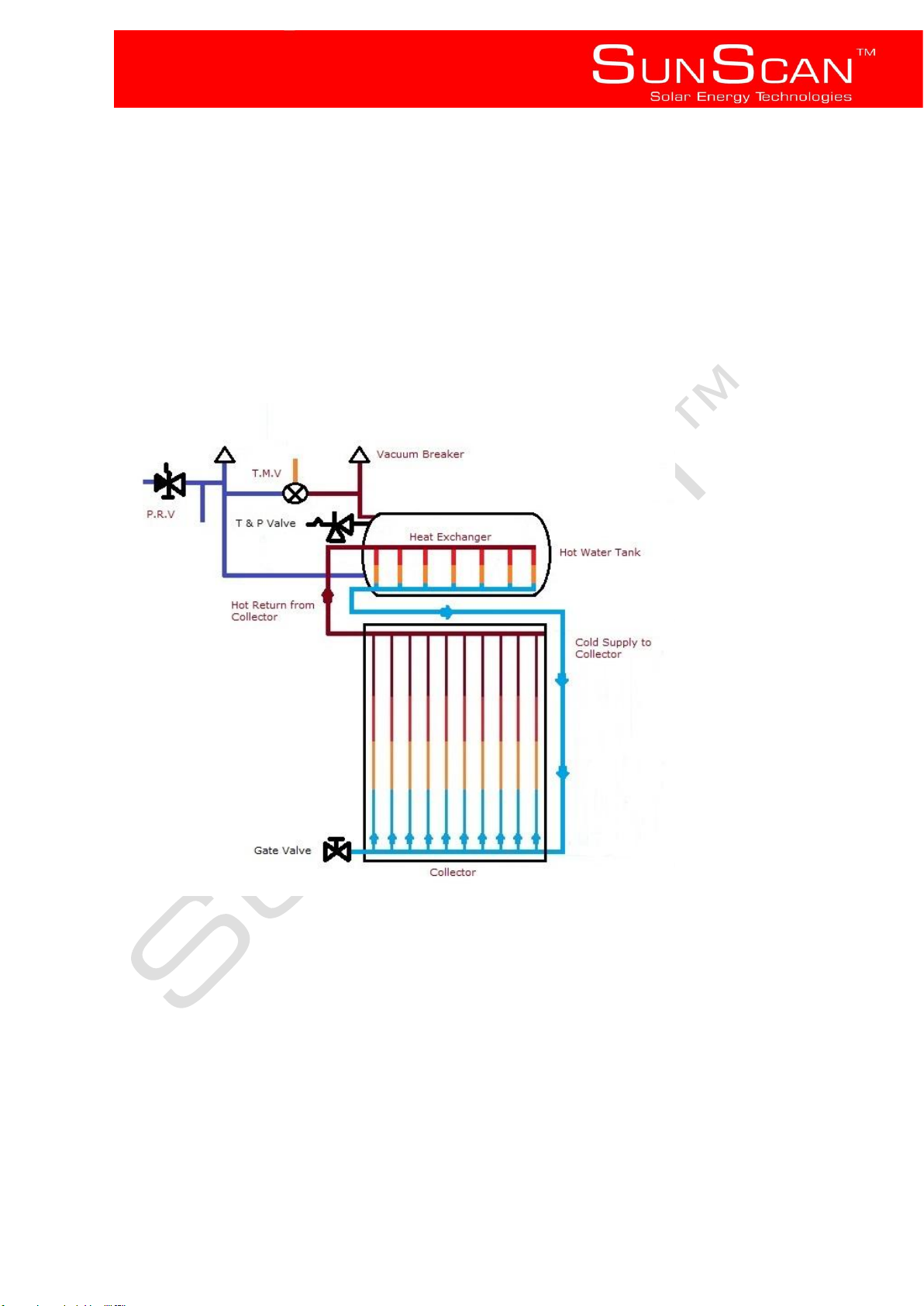
Diagram A
Safety valves and vacuum breakers
All Safety valves, including pressure reducing valves and vacuum breakers must be installed in compliance with
SANS 198, SANS 10254 and SANS 10106
Installation of the Cold Supply and Hot return to and from Collector
Always ensure that the hot return from the collector is connected to the highest connection point, and that the
cold supply to the collector is connected to the lowest connection point opposite to the ‘hot return from collector’
connection. (See diagram A),it is recommended that a Gate Valve be installed on the port directly opposite to the
cold supply to collector (See diagram A) (this will aid in the filling process listed in 4.7 adding the heat transfer
fluid).A 22mm compression type stop end shall be placed on the remaining ‘open’ port (Directly opposite the hot
return on collector) Do not create any sharp or unnecessary bends in the pipe work and ensure a gentle gradient
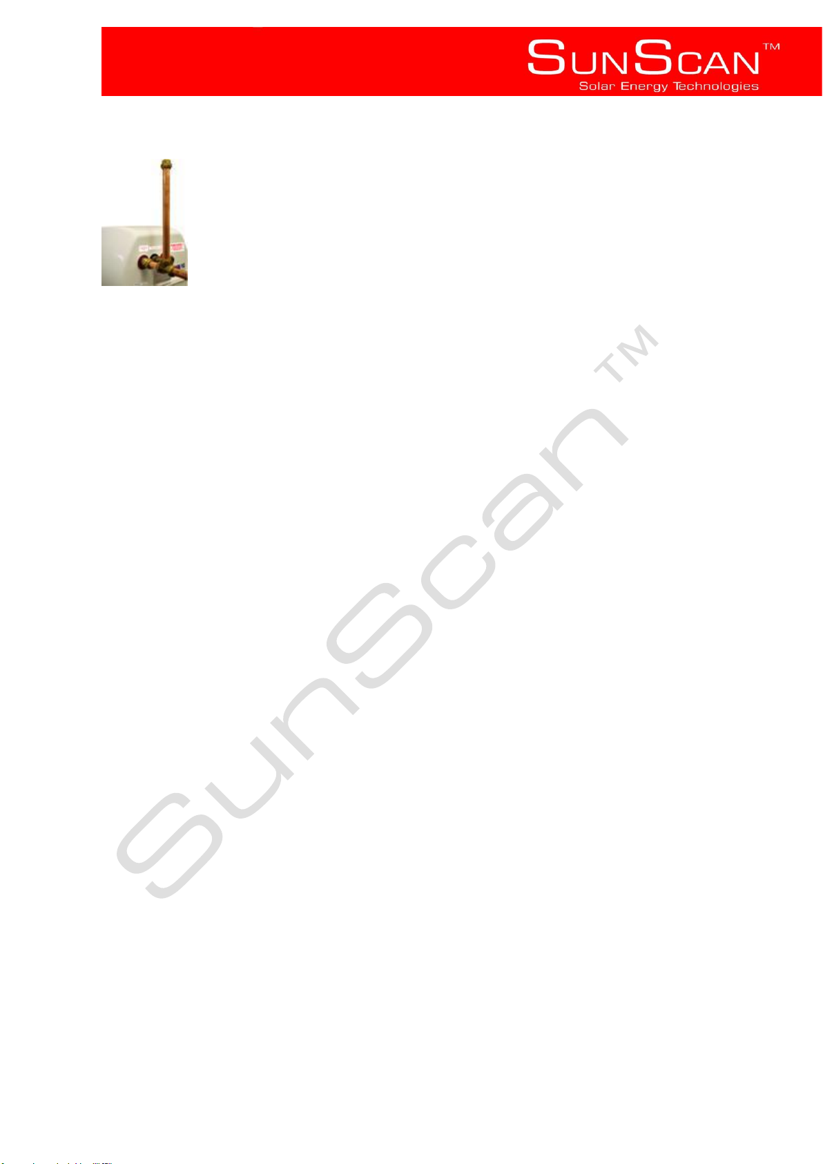
to and from the collector. Install a Compression type ‘T’ piece fitting on the hot return near the tank and insert a
300mm length of 22mm copper tubing vertically and up right into this t – piece, tighten the connection (See
diagram B) (this too will aid in the filling process listed in 4.7 adding the heat transfer fluid)
Page 16
SunScan™ Technologies
- 15 -
Diagram B
Installation of Anti-Scalding/Thermostatic Mixing Valve
Ensure that both hot and cold water supplied to the valve are of equal pressure, and that any markings directing
or depicting the flow of water are adhered to.
For safety reasons, it is essential to install a thermostatic mixing valve. This valve controls the temperature of the
water at the point of use. Make sure that the valve has been set to allow a suitable maximum temperature and
has not been set to by-pass. The temperature ranges from 38°C – 65°C.
We recommend a setting that does not exceed 55°C at the point of use.
4.7 Adding the heat transfer fluid
Note: This is done prior to filling the tank listed in 4.9 commissioning
Using a flexible hose attach one end to the Gate valve at the bottom of the collector (See diagram A) (ensure the
gate valve is open), with the other end of the hose slightly higher than the top of the 300mm copper pipe inserted
into the ‘T’ piece (See diagram B), add the heat transfer fluid until the 300mm pipe over flows with the glycol
solution, by filling from the bottom of the collector any air trapped in the system will be forced out of the open end
of the 300mm pipe, shut the gate valve and remove the hose, using a 22mm stop end compression fitting seal off
the top of the 300mm pipe.
Important
Ensure that there is no air trapped in the collector or piping as this will have a negative effect on your system’s
performance, if required repeat 4.7 adding the heat transfer fluid to remove any air still trapped in the system.
4.8 Electrical installation
Always ensure that the hot water tank is filled with water before commissioning any electrical components.
The installation and connection of electrical components must be carried out by a qualified electrician.
Note: No modifications to the original geyser thermostat are allowed. This is to maintain all fuse and or thermal
cut-out protections.
4.9 Commissioning
• Check that all nuts and bolts securing the collector and hot water tank to the stand are tight and that all
anchoring points to the roof are secure.
• Make sure all plumbing connections have been tightened and all pipe work has been secured.
• Check that the drain cock is closed
• Ensure that all electrical connections are secure and covered.
• Ensure that there are no leaks between the collector and the tank and that all the air has been removed.
Page 17

SunScan™ Technologies
- 16 -
Step 1
Ensure that there is water supplied to the property and that at least one hot water point of use that will be
supplied by the SunScan system is open, this will allow any air trapped in the system to be expelled, at the
hot water tank open the valve that isolates the water from the tank, allow the tank to fill, at the point of use
opened prior to filling ensure that all of the air has been expelled, this may take several minutes, once a steady
stream of water appears ensure that all points of use are closed so that the system may pressurise.
Step 2
Check for any water leaks at all plumbing joints; also ensure that there are no leaks on the solar loop containing
the heat transfer fluid.
Step 3
Shut off the mains water supply to the system and open any inline strainers and clean any debris that might have
accumulated, this is particularly important if the dwelling is new as there is often debris in the mains water supply.
Re-open the supply after.
Step 4
Remove any covering from the collector and allow the system to heat, if applicable use a multi-meter to test that
the heating element is switching on and drawing the correct amount of amps.
Step 5
Re-check the system for leaks after it has heated, if a leak is suspected on the solar loop cover the collector and
allow to cool, repeat 4.7 adding the heat transfer fluid
4.10 Check list
The following check list must be observed before handing the system over.
• All air has been removed from the system (See 4.7 adding the heat transfer fluid and 4.9 Commissioning)
• There are no water leaks on the system and or any pipes carrying water to points of use.
• There are no leaks on the solar loop between the collector and heat exchanger.
• Roof tiles have been placed back in position
• Roof flashing and any waterproofing is water tight.
• All drain pipes are free of obstruction
• All hot water pipe work and piping to and from the collector is insulated.
5 Operating instructions
5.1 Start up procedure
If for any reason the water supply to the property and or solar system is interrupted e.g. municipal works or
maintenance, and the system requires re-commissioning, follow steps 1-6 of 4.9 Commissioning, always ensure
that the relevant safety procedures are adhered to.
5.2 Emergency shutdown procedure
Should the need arise and the system is damaged or leaking hot or cold water, the supply shut off valve must be
closed immediately and power to the heating element turned off.
5.3 System performance
The amount of hot water generated and available is dependent on usage patterns and the weather experienced.
Solar radiation is greater on clear, sunny days, between 9am and 3pm, during periods of use the system can
operate at roughly twice the maximum ambient temperature and during periods of non use is capable of
achieving well over 70°C.
Ensure that any trees that may cause shading during the afore mention times are regularly pruned.
To get the most out of your solar water heating system we suggest the following:
• Take showers instead of baths as generally they use less hot water.
• Use the bulk of your hot water requirements in the evening instead of the morning, this will maximize the usage
of free energy harvested during the day.
Page 18

SunScan™ Technologies
- 17 -
5.4 High water temperatures
The SunScan SunStream Indirect system is capable of reaching temperatures that exceed 60°C. This
may occur during prolonged periods of direct sunlight and particularly in summer, and or long periods of reduced
water usage. Extreme care should always be taken.
Although every system is fitted with a thermostatic mixing valve that regulates temperature at the point of use,
always check the water before use to ensure it is suitable for its intended purpose and to prevent scalding.
6 Maintenance
6.1 Routine maintenance
Note: These are suggested schedules and may need to be carried out more frequently depending on water
quality .e.g. areas with high incidents of water deposits such as magnesium and or calcium.
• Always ensure that the collector is clean and that no dirt has collected on the surface as this will affect
performance, if required use a soft cloth and fresh water to carefully wipe the glass clean, ensure that this is
carried out early in the morning before the collector has had a chance to heat.
• Regular checks should be done to see that no damage has occurred to the system and that the system and
pipe work are free of any leaks.
• The system should be drained bi- annually and flushed; this is to remove any scale build up that might have
Occurred due to poor water quality.
• A periodic inspection of all valves should be carried out, this includes but is not limited to temperature and
pressure relief valves, pressure reducing valves, expansion valves, vacuum breakers and thermostatic mixing
valves, these valves allow for the safe operation of the system and should be inspected bi- annually by
a trained professional.
• Temperature and pressure relief valves as well as expansion valves may release small amounts of water each
day whilst heating, this is a normal function, as heated water expands by approximately 1L out of 50L of its
volume, if these valves leak continuously however, this may indicate failure and may need replacement.
if unsure contact a authorised installer.
It is important that the discharge from these valves are not sealed off, and are left open to the
atmosphere, these valves must discharge safely without harm to persons or property.
• All filters and strainers are to be checked and cleaned regularly.
• Heat transfer fluid levels should be checked every 2 years and replenished if required.
• Check mountings on collector regularly for weathering and or fatigue.
• Pipe insulation should be checked for degradation and damage and replaced if necessary, always be aware of
high temperatures emitted from the collector and pipe work when carrying out any maintenance that might put
you at risk of scalding.(ensure the correct safety precautions are taken)
• If at any time the temperature at the point of use seems to be increasing or decreasing contact an authorised
Installer as the thermostatic mixing valve may need adjustment or repair.
• Any repairs or replacements of any parts must be performed by an authorised installer.
• In case of emergency, for example, damage to the collector, tank or pipe work is evident, shut off the water
supply to the system ,switch off the power to the heating element immediately and contact an
authorised installer.
• Any inspections, visual or otherwise carried out by person or persons that result in
injury or death and or damage to property, shall not hold Solar Lifestyles cc t/a SunScan or any of their affiliates
liable.
Page 19
SunScan™ Technologies
- 18 -
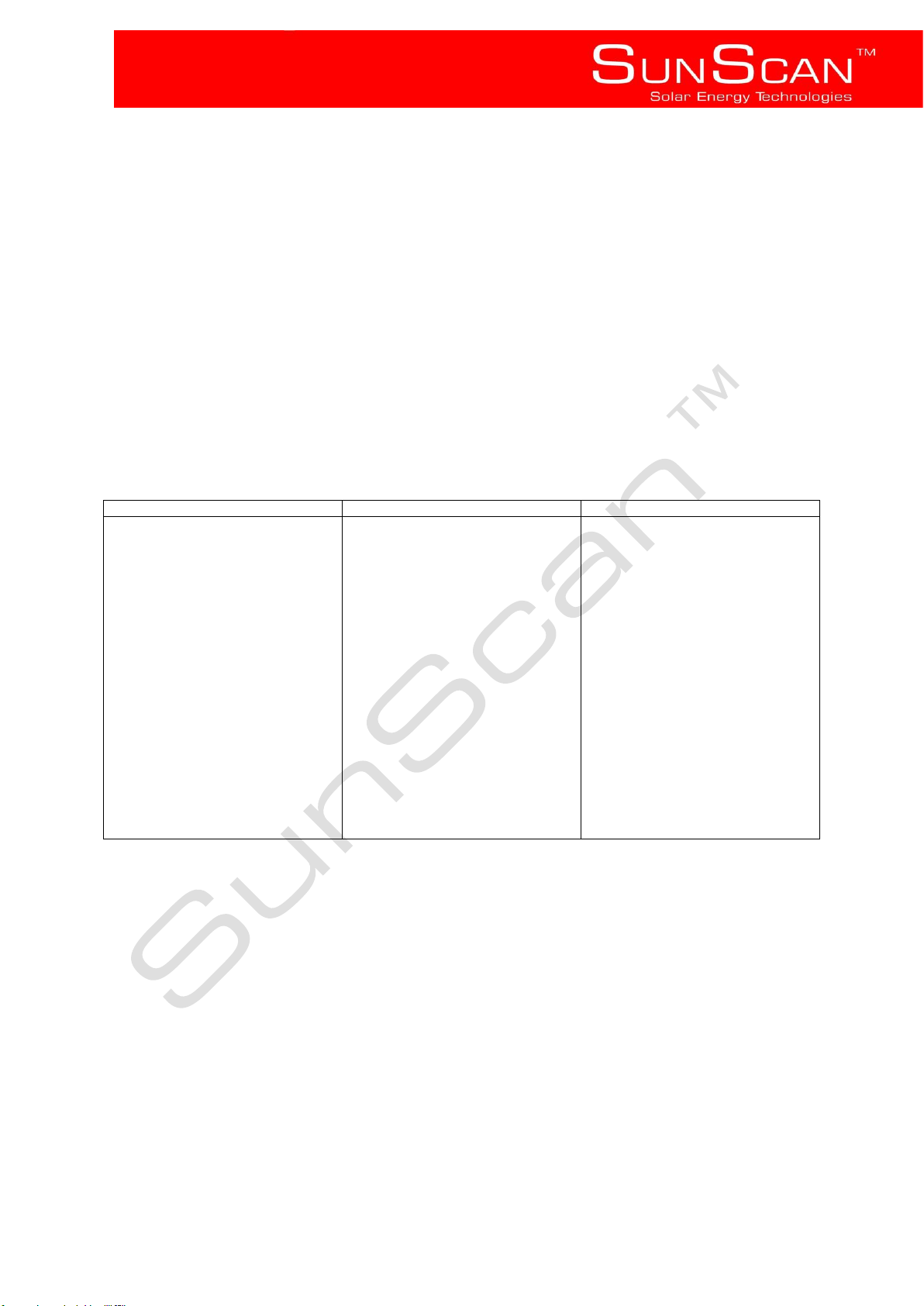
Problem
Possible cause
Corrective action
Little to no solar heat contribution
Low solar radiation, Shading,
Tempered glass cover is dirty, Air
trapped in the collector and or
piping to and from collector, Hot
water leak, little to no heat transfer
fluid.
On days with low solar radiation
ensure that the backup heating
element times are adjusted
according to hot water
requirements, Always ensure that
any trees that may cause shading
are pruned regularly, visually
inspect collector and clean
tempered glass if required, Natural
convection will not occur
successfully if there is any air
trapped in the collector or piping
connecting to tank, remove air by
draining the solar loop and refilling
(See. 4.7) , this must only be done
by a trained professional, Inspect
the system for any leaks, if a leak is
suspected shut off water supply to
system and contact your dealer,
replenish the heat transfer fluid.
6.2 Trouble shooting
Before applying any of the trouble shooting techniques listed below:
• Ensure that the power to the heating element has not been interrupted i.e. all relevant circuit
Breakers and or isolator switches are in the on position.
• Ensure that the water supply to the storage tank has not been interrupted and inadvertently drained for example
, municipality working on water mains.
• Contact an authorised installer if after checking the above there is still no hot water.
Page 20
SunScan™ Technologies
- 19 -
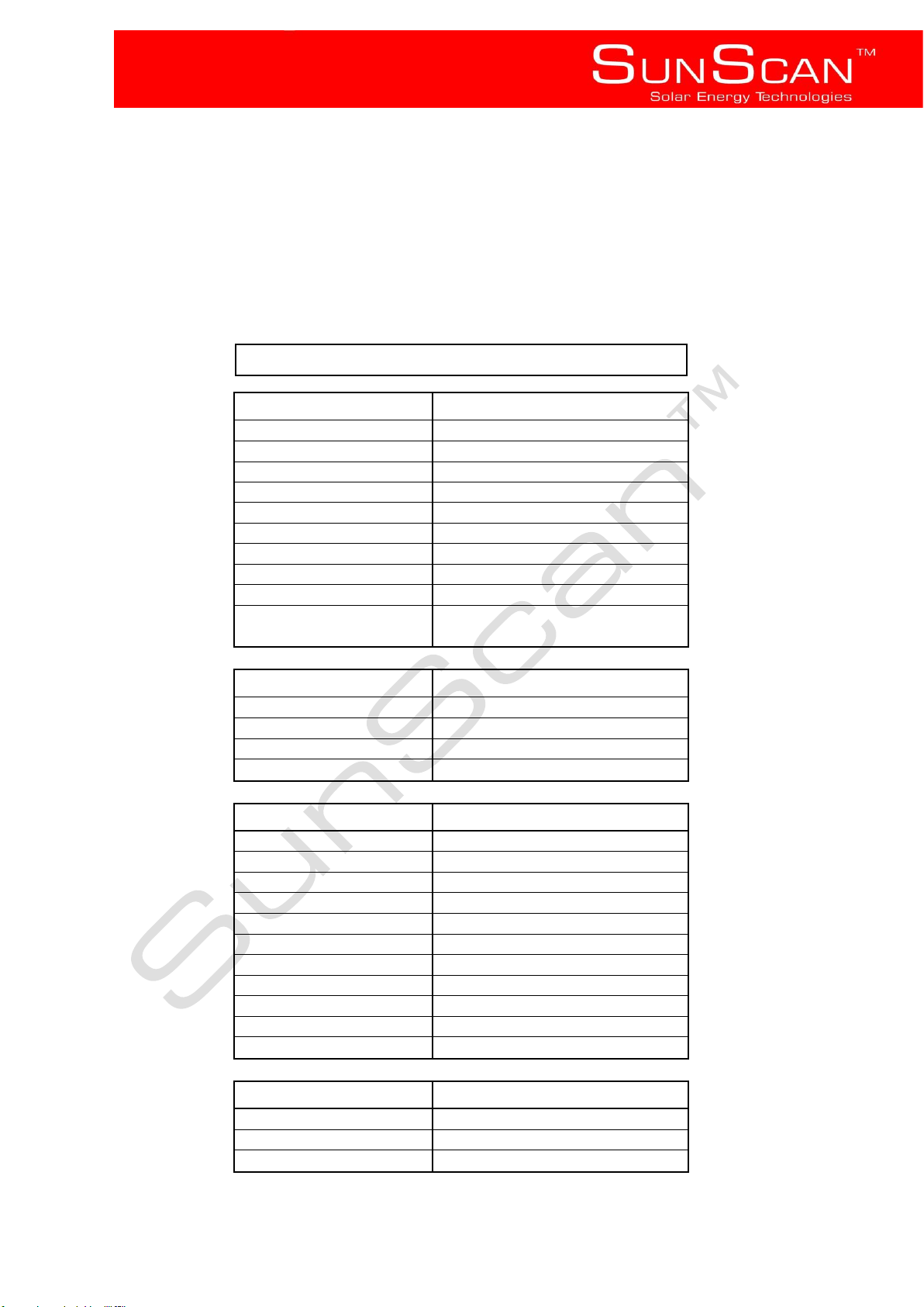
Collector Type
SS-FP-2.4
General Information
Standard Dimensions
2.005m x 1.200m
Gross Area
2.40
Aperture Area
2.24
Absorber Area
2.210m²
Number of Covers
1
Cover Material
tempered glass
Cover Thickness
3mm
Cover Transmission
88%
Weight
38kg
Power output at 1000W/m2
(tm-ta) = 30 °C
1244 W
Casing
Frame Material
Aluminium
Frame Colour
Bronze Brown
Back Plate Material
Aluminium
Sealing Gasket
Ethylene-Propylene Diene Monomer
Absorber
Material
Aluminium
Thickness of Absorber Plate
0.5mm
Surface Treatment
Cu and Al complex
Volume of Absorber
1.99 L
Header Material
Copper
Header Tube Size
22mm
Riser Material
Copper
Riser Tube Size
12mm
Operational Pressure
600kPa
Test Pressure
1500 kPa
Stagnation temperature
153 °C
Thermal Insulation
Insulation Material
Glass Wool
Back Insulation Thickness
35mm
Side Insulation Thickness
25mm
7 Technical specification
2 .4m² SunScan Flat plate collector specification
SS-FP RANGE
Page 21
SunScan™ Technologies
- 20 -
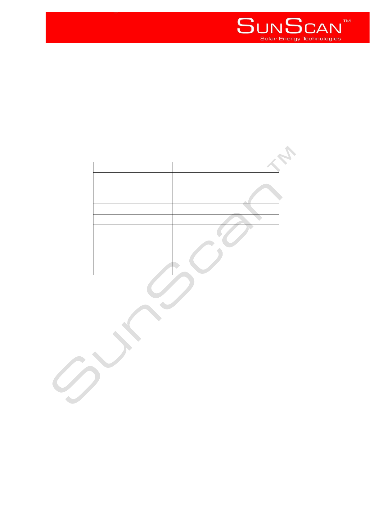
Width
485mm
Height
485mm
Length
1520mm
Weight
30kg
Fitting Sizes
¾ “ BSP
IPX Rating
4
Water Conditions
Suitable for all Water Types
Electrical Backup
2kw Element & Thermostat
Orientation
Horizontal
Maximum Operating Temp.
93°C – 98°C
Heat Loss
<1.94kw / 24Hrs
Xstream Solarstream 150L Indirect Hot Water tank Specification
Page 22
SunScan™ Technologies
- 21 -
Product
Parts
Labour
Xstream 150L Indirect
(warranty provided by
Xstream Geysers)
5 years on Tank only
1 year on Element
1 year on Thermostat
1 year
SunScan Collectors
5 years
1 year
Thermostatic Mixing Valve
2 years
1 year
WARRANTY CERTIFICATE
Solar Lifestyle warrants the functionality of the components of their SunScan product as follows:
The system is covered for the indicated period from the date of installation and is provided under the
following conditions:
It was installed by a SunScan Certified Installer or Implementation Partner.
It is only supplied by municipal water with a total dissolved hardness of less than 600 ppm at
maximum working pressure of 400 KPa.
The system is not left standing uncovered with no water supply for longer than 14 days.
All requirements as detailed in the installation manual were complied with.
A Plumbing and electrical Certificate of Compliance was Issued.
This warranty only applies to the solar system product parts listed above and does not apply
to any additional electrical and/or plumbing parts supplied by the installer or the installation.
Should a part of the solar system product be replaced during this period, only the balance of
the original warranty will continue to remain effective.
Solar Lifestyle is excluded from responsibility from any consequential loss including: injury to
persons, damage to property, economic loss, any legal or other damages due to
manufacturing defect. Consequential loss shall be covered by the general household
insurance policy of the home owner.
Swimming pool, Spa and Jacuzzi water may not be circulated through the collector.
The warranty does not include damage caused by freezing.
Collectors connected in series must make use of flexible couplings.
Accidental breakage is not covered by this warranty, and should be added to your general
household insurance policy.
Replacement or repair excludes all transport costs.
Should a dispute arise from an installation, or from the product, the dispute will be referred to
SESSA for arbitration and the parties will be held by the arbitrators’ decisions.
Geyser and geyser components warranteed by Xstream Geysers Tel: +27 21 872 0900
Tempering valves and Air release valves should be serviced biannually.
Register Warranty
(Please supply details below and fax or email to SunScan Technologies)
Name and Surname:
Installation Date:
Installation Address
Page 23

SunScan™ Technologies
- 22 -
9 Sign off (customer copy)
Supplier details Installer details
Solar Lifestyle cc t/a SunScan™ Company Name:
__________________________
Physical address Unit S17 Spearhead Address: __________________________
Business Park
Montague Drive __________________________
Montague Gardens
Cape Town __________________________
7441
__________________________
Postal address Suite No. 73, Private Bag x 7
Chempet, 7442 __________________________
Tel +27 86 100 5684 Tel: __________________________
Fax +27 86 689 4401 Fax: __________________________
Email [email protected] Email: __________________________
Installer Sign-off Customer acceptance
Installer Name: ________________________ I, ________________________________________
Installation date: ________________________ , (I.D. No)__________________________________
hereby declare that the solar system has been
Location: ________________________ installed to my satisfaction, it has been
demonstrated to me and is in working order and I
Customer Name: ________________________ have been instructed in its operation, maintenance
and usage.
Customer address: ________________________
________________________ Product Serial No: _________________________
________________________
The installer hereby warrants that the system has
been installed in accordance with this instruction
booklet and product specific training received.
____________________ _______________ ____________________ _______________
Installer signature Date Customer signature Date
Page 24

SunScan™ Technologies
- 23 -
10 Sign off (installer copy)
Supplier details Installer details
Solar Lifestyle cc t/a SunScan™ Company Name: __________________________
Physical address Unit S17 Spearhead Address: __________________________
Business Park
Montague Drive __________________________
Montague Gardens
Cape Town __________________________
7441
__________________________
Postal address Suite No. 73, Private Bag x 7
Chempet, 7442 __________________________
Tel +27 86 100 5684 Tel: __________________________
Fax +27 86 689 4401 Fax: __________________________
Email [email protected] Email: __________________________
Installer Sign-off Customer acceptance
Installer Name: ________________________ I, ________________________________________
Installation date: ________________________ , (I.D. No)__________________________________
hereby declare that the solar system has been
Location: ________________________ installed to my satisfaction, it has been
demonstrated to me and is in working order and I
Customer Name: ________________________ have been instructed in its operation, maintenance
and usage.
Customer address: ________________________
________________________ Product Serial No: _________________________
________________________
The installer hereby warrants that the system has
been installed in accordance with this instruction
booklet and product specific training received.
____________________ _______________ ____________________ _______________
Installer signature Date Customer signature Date
 Loading...