

Page 1

SunRotor® Solar Pump
Installation and Resource Manual
Page 2

CONTENTS
1 Introduction .................................................................................................................................................. 3
2 Warranty Registration Form ...................................................................................................................... 4
3 Warnings ....................................................................................................................................................... 5
4 Solar Water Pumping System .................................................................................................................... 6
4.1 SunRotor® Submersible Pump ............................................................................................................. 7
4.2 SunRotor® Controller ............................................................................................................................ 7
5 Solar Array Installation .............................................................................................................................. 8
5.1 Sizing the Solar Array ........................................................................................................................... 8
5.2 Location of the Solar Array .................................................................................................................. 8
5.3 Solar Orientation ................................................................................................................................... 8
5.4 Solar Array Mounting Rack ................................................................................................................. 8
5.5 Mounting Pole Guide for Top-Of-Pole Mounts ................................................................................ 9
5.6 Seasonal Tilt of the Solar Array ......................................................................................................... 10
5.7 Solar Array Wiring .............................................................................................................................. 10
5.8 Grounding and Lightning Protection ............................................................................................... 12
6 Pump Controller Installation .................................................................................................................. 15
6.1 Pump Controllers & Accessories....................................................................................................... 15
6.2 Locating and Mounting the Controller ............................................................................................ 16
6.3 Indicator Lights .................................................................................................................................... 16
6.4 Remote Float Switch ........................................................................................................................... 17
7 Pump Preparation ...................................................................................................................................... 17
7.1 Wire Sizing ........................................................................................................................................... 17
7.2 Installing the Check Valve ................................................................................................................. 18
7.3 Splicing the Wires ................................................................................................................................ 19
7.4 Safety Rope ........................................................................................................................................... 19
7.5 Low Water Sensor ............................................................................................................................... 19
7.6 Freeze Protection ................................................................................................................................. 20
7.7 Binding Pipe, Cables, & Rope ............................................................................................................ 20
7.8 Wellhead Components ....................................................................................................................... 21
Page 1 www.sunrotor.com
Page 3

7.9 Allowance for Pipe Stretch ................................................................................................................. 21
7.10 Coping with Dirty Water Conditions ........................................................................................... 21
7.11 Water Sanitization ........................................................................................................................... 22
8 Pump Installation ...................................................................................................................................... 22
8.1 Assembling the Drop Pipe, Cables, and Safety Rope .................................................................... 22
8.2 Machine Installation ............................................................................................................................ 22
8.3 Hand Installation ................................................................................................................................. 23
8.4 Running the Cables ............................................................................................................................. 23
9 Wiring the System ..................................................................................................................................... 24
9.1 Electrical Warnings ............................................................................................................................. 24
9.2 Wiring the Controller .......................................................................................................................... 24
9.3 Wiring Power to the Controller ......................................................................................................... 26
9.4 Post-Installation Testing ..................................................................................................................... 26
10 Troubleshooting......................................................................................................................................... 26
10.1 If the Pump Doesn’t Run ................................................................................................................ 26
10.2 Inspect the System ........................................................................................................................... 27
10.3 Electrical Testing .............................................................................................................................. 28
10.4 Troubleshooting Checklist ............................................................................................................. 30
11 Maintenance ............................................................................................................................................... 30
11.1 Helical Rotor Pump End Maintenance ......................................................................................... 31
11.2 Centrifugal Pump End Maintenance ............................................................................................ 31
11.3 Pump Motor Repair ......................................................................................................................... 31
11.4 Solar Panel Maintenance................................................................................................................. 31
11.5 Miscellaneous ................................................................................................................................... 32
11.6 Repairs and Replacements ............................................................................................................. 32
12 About Solar Power & Pump Company.................................................................................................. 33
13 Additional Information ............................................................................................................................ 34
www.sunrotor.com Page 2
Page 4

1 INTRODUCTION
To gain the maximum level of service and satisfaction from your pumping system, please carefully
read the contents of this guide before installation. Should any questions arise after reading through
this installation guide, please contact your local Authorized SunRotor® Dealer, or call the SunRotor®
Technical Service Team at 1-580-303-4015. Follow all appropriate state and federal electrical codes.
Please read through the warranty information carefully before installation. Check the depth limits for
your custom panel/pump configuration. Depth limits can be found on the pump data sheets. If at
any time, additional copies of this installation guide, warranty information, or data sheets are
needed, they may be obtained on the SunRotor® website under the Downloads section or directly by
visiting www.sunrotor.com/downloads.
© 2014 Copyright by Solar Power & Pump Company, LLC. All Rights Reserved.
REGISTRATION FORMS
Please look through the following form and fill out before, during, and after as needed. This form is
necessary to REGISTER YOUR WARRANTY. The information provided will assist in fixing or
troubleshooting any future technical issues, as well as provide the proper background information
should any repairs or replacements be needed. Please make a copy of this form to keep with the
pump records. Listed below is the mailing address where the registration form can be sent.
Alternatively, the form can be filled out electronically by visiting the link provided below.
Mailing Address:
Solar Power & Pump Company
301 W 12th St.
Elk City, OK 73644
Online Registration:
www.sunrotor.com/warranty-registration
Thank you for your assistance and participation. If we can be of any further assistance, please call us
at 1(866) 246-7652, e-mail one of the following e-mail addresses, or use the contact form provided on
the website:
Technical Service: service@sunrotor.com
General Information: info@sunrotor.com
Contact Form: www.sunrotor.com/contact
The SunRotor® Solar Products Team
Page 3 www.sunrotor.com
Page 5

2 WARRANTY REGISTRATION FORM
Name
Address
Phone Number
Purchased From
Date of Purchase
Pump Model
Pump Serial Number
Controller Model
Controller Serial Number
System Power
PV-Direct
Battery System
If PV:
Number of Panels
Solar Panel Brand
Solar Panel Wattage
Watts
Operating Voltage
V
Well Depth
ft
Casing Diameter
inches
Static Water Level
ft
Pump Set Depth
ft
Lift above ground level
ft
Discharge Pressure, In Any
PSI
www.sunrotor.com Page 4
Page 6

3 WARNINGS
CAUTION: disregarding may
result in damage to equipment
and VOIDING OF WARRANTY
WARNING: disregarding may
result in SERIOUS INJURY OR
DEATH
Please review the following warnings. These are listed for both personal safety and the safety of the
products. Disregarding or ignoring these warnings can result in SERIOUS INJURY and/or VOID YOUR
WARRANTY. All SunRotor
system is being installed without a licensed pump installer, an electrician or knowledge of electrical
circuits is HIGHLY recommended. If any questions or concerns regarding these warnings should arise,
please contact your Authorized SunRotor® Dealer or the SunRotor® Technical Services Team at 1-580303-4015. Solar Power & Pump Company, LLC is NOT LIABLE for any DAMAGE or INJURY.
®
Solar Pumps should be installed by a licensed pump installer. If this
All SunRotor
controller and void the warranty. Do NOT exceed the following open circuit voltages: SRC-M50T:
50VDC; SRC-M100T: 100VDC; SRC-M200T; 200VDC. For all other controllers, please contact the
SunRotor® Technical Services Team. See Section 9.2 Wiring the Controller.
The system should be installed and serviced by qualified personnel only. All electrical codes should be
observed. Make ABSOLUTELY CERTAIN all power sources are disconnected prior to wiring.
Extreme heat can damage the pump. Protect the pump from sunlight or other heat sources.
SunRotor
fill the pipe with debris. Running it under these conditions may damage the pump and VOID YOUR
WARRANTY. Do NOT use the pump to develop a new well or purge a dirty well.
Install proper system grounding for safety and lightning protection. Although the warranty does NOT
cover damage caused by ACTS OF GOD, proper grounding can significantly reduce the chance of
extreme damage. See Section 5.8 Grounding and Lightning Protection.
Follow all wire sizing recommendations on pump data sheets. Under-sizing the wires can cause the
pump to experience low power failure.
Do not touch controller input or pump wires together to test for a spark.
Do not run the pump dry.
The cable splice must make a water-tight seal to the OUTER JACKET of the pump cable. See Section 7.3
Splicing the Wires.
There are potential hazards in handling any heavy mechanical assembly. If you have any doubts about
your ability to perform the Hand Installation SAFELY, please hire a professional pump installer. Do not
use a winch or a vehicle. See Section 8.3 Hand Installation.
Do not run the pump against a blocked or restricted outlet.
Please pay close attention to the following symbols throughout this guide:
®
controllers have a maximum voltage rating. Exceeding these ratings will destroy the
®
solar pumps are CLEAN WATER PUMPS. Extreme sand or silt may cause the pump to stop or
Page 5 www.sunrotor.com
Page 7

4 SOLAR WATER PUMPING SYSTEM
1. PV Panel Array
2. Solar Module Mounting Rack
3. Water Pipe
4. Well Seal Assembly
5. Low Water Sensor
6. Submersible Pump
7. Conduit and Wiring from Controller to Well Seal
8. Wiring Harness from Controller to Solar Modules
9. DC Input Controller
10. Tank Full Tethered Float Switch with Weight
11. Anti-freeze Bleeder Valve
FIGURE 4-1 SOLAR PUMP DIAGRAM
www.sunrotor.com Page 6
Page 8

4.1 SUNROTOR
®
SUBMERSIBLE PUMP
The SunRotor® submersible pump line offers a varied selection depending on the requirements.
From low cost to high yield, the SunRotor® Sales Team can find a solar pump system to fit nearly any
request. Both helical rotor and centrifugal pumps are offered, in a range of 12V to 110V brushless DC
motors. The conventional brushed DC motor maintenance and replacement is not necessary with
brushless DC motors.
The helical rotor series offers something that many pumps cannot: the ability to easily repair it in the
field. If the well has any abrasive substances such as sand, the rotor and stator can begin to show
wear and tear over time; however, with the SunRotor® Helical Rotor Repair Kit, it’s as easy as
removing the casing on your pump end, screwing in the new rotor, and placing the new stator in its
place in the pump end. After bolting everything back into place, the pump will run like it was new.
If for any reason the motor goes out (no matter the warranty status), the SunRotor® Technical Services
Team can most likely rebuild it, which is much more cost effective than purchasing a new pump.
For more information on the SunRotor® solar pump line and accessories for water pumping systems,
contact the SunRotor® Sales Team at 1(866) 246-7652.
4.2 SUNROTOR
®
CONTROLLER
The SunRotor® controller offers state of the art controller electronics, housed within a highly durable
metal weather resistant connection box with cooling fins cast on the back. It has a clear cover which
allows visible inspection of all of the connections and LED status lights. It offers a wide operational
range with max input tolerances of 50/100/200 volts DC, and it converts excess voltage into amperage
with its linear current boosting feature.
The controller also offers a timer function that is used to adjust the delay time for the low water
switch. The standard setting for the delay timer is 20 minutes, but can be increased by turning the
knob clockwise and reduced by turning it counterclockwise. This setting can be adjusted between 0
and 30 minutes while the controller is either on or off. The delay is designed to allow well recovery
before the pump is restarted. This significantly reduces the number of times the pump cycles on and
off throughout the day, and likewise, reduces the chance of damage to the pump from unnecessary
wear and tear.
Another option is the speed control. The speed knob adjusts the RPMs of the pump and has the
default position set to the maximum. Like the Timer Control Knob, clockwise movement increases
and counterclockwise movement decreases this value. Speed control can be useful in maintaining the
water level in a low producing well or water source, as it can be set to match the pumping speed with
the production level specific to the water source. Additionally, properly regulating the speed of the
pump can produce a more consistent water flow and prolong the life of the pump, as there will be
less startups each day. The speed control can be adjusted with the system on or off.
Page 7 www.sunrotor.com
Page 9
5 SOLAR ARRAY INSTALLATION
5.1 SIZING THE SOLAR ARRAY
Be sure that the PV array has been properly sized to meet the pump's power requirement. A PV
array will only produce its rated power when properly aligned with the sun and no dust or debris
accumulation. Solar panels offer peak performance in cooler temperatures. An undersized array can
cause poor starting and reduced flow in low light conditions. An oversized array is recommended (at
least +20%); the pump will start earlier and run later, as well as have higher performance on cloudy
or hazy days.
5.2 LOCATION OF THE SOLAR ARRAY
Install the solar array in a location that will maximize sun exposure. If necessary, it may be placed a
substantial distance from the wellhead to gain sun exposure, reduce visibility, etc. The greater the
distance, the larger the electrical wire must be, so cost rises with distance.
ATTENTION: Shading a portion of a PV array will stop the pump. Each PV module
(panel) contains a series of small solar cells. Any cell that is shaded acts like a resistor
and will reduce the output of the entire module. So, shading just one corner of the solar
array will reduce the power substantially, slowing or possibly stopping the pump.
5.3 SOLAR ORIENTATION
For optimal performance, the solar array must be oriented within 10° of true (solar) south.
Depending on location, a compass reading may show an error of as much as 20°. To correct this
discrepancy, apply the magnetic declination for the region. Many regional maps indicate the
magnetic declination. Additionally, this information can be found on the National Geophysical Data
Center website (http://www.ngdc.noaa.gov/geomag-web/#declination).
5.4 SOLAR ARRAY MOUNTING RACK
CAUTION: Use a mounting structure engineered for wind resistance, ease of adjustment,
and most importantly, safety. Follow any and all instructions and cautions provided
with the mounting rack.
For the best quality and economy, factory-built mounting racks are recommended. Pole-top racks are
especially popular for solar water pumps. Factory-built racks are available from your Authorized
SunRotor® Dealer.
Place the bottom of the array at least 2 feet (.6 m) above ground to clear rain spatter, growing
vegetation and snow. Keep in mind that trees and perennial plants will grow taller over the years.
A pole-top mounted rack is advised. It allows the array to be placed high enough to clear the reach of
livestock, people and growing vegetation—potentially eliminating the need for fencing. If the rack is
www.sunrotor.com Page 8
Page 10
to be placed higher than approximately 6 feet (2m), it is advisable to weld its mounting pipe to
Module
Area
Pole Size
(Steel Pipe)
Depth
in Ground
Height*
Above Ground
Hole
Diameter
15 SQ. FT.
2" SCH40 (2-3/8" OD)
30"-36"
48"-72"
8"-12"
20 SQ. FT.
2.5" SCH40 (2-7/8" OD)
34"-40"
48"-72"
10"-14"
28 SQ. FT
3" SCH40 (3-1/2" OD)
36"-42"
48"-72"
12"-16"
35 SQ. FT.
3" SCH40 (3-1/2" OD)
38"-44"
60"-72"
12"-16"
60 SQ. FT.
4" SCH40 (4-1/2" OD)
42"-48"
60"-72"
16"-24"
90 SQ. FT.
6" SCH40 (6-5/8" OD)
48"-60"
60"-84"
24"-30"
120 SQ. FT.
6" SCH40 (6-5/8" OD)
48"-72"
72"-84"
24"-30"
160 SQ. FT.
8" SCH40 (8-5/8" OD)
60"-78"
84"-102"
30"-36"
180 SQ. FT.
8" SCH40 (8-5/8" OD)
60"-78"
84"-102"
30"-36"
`225 SQ. FT.
8" SCH80 (8-5/8" OD)
72"-84"
96"-120"
36"
260 SQ. FT.
8" SCH80 (8-5/8" OD)
72"-84"
96"-120"
36"
another pipe one size larger, to tolerate wind loads. Refer to your rack manufacturer’s instructions.
PLEASE NOTE: adding additional panels and using a fixed position mount is normally more economical
than solar tracking systems. The increased production from extra panels compensates for the lack of
tracking, and eliminates the extra costs of having to repair and maintain the tracking system. Please
consult your Authorized SunRotor® Dealer for more information.
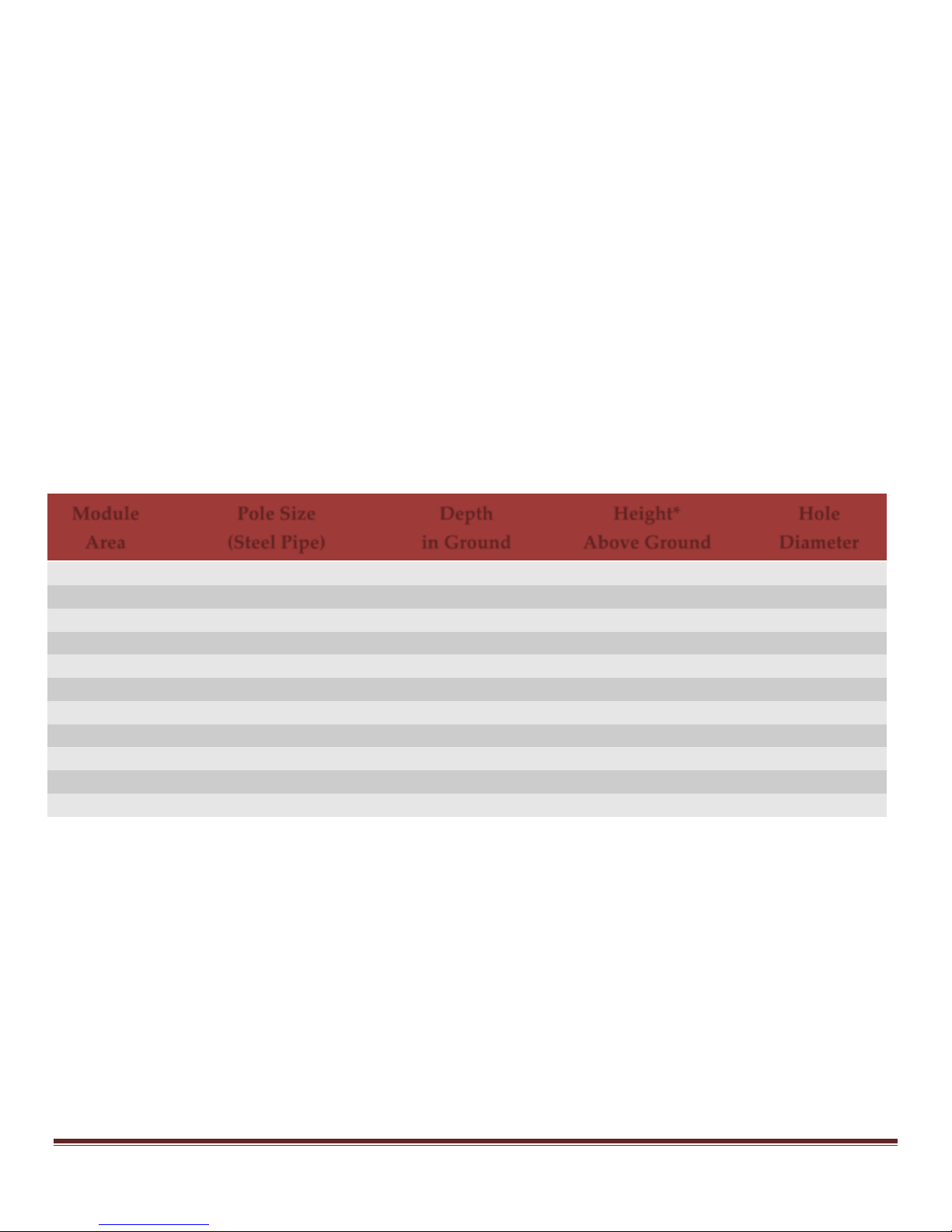
5.5 MOUNTING POLE GUIDE FOR TOP-OF-POLE MOUNTS
The following table provides guidelines for an average installation. Soil type varies widely from one
region to another. The actual depth and diameter of the hole and the amount of concrete used is very
dependent on soil type. Installations in loose, sandy soil will require a larger, deeper hole with more
concrete than an installation in hard, rocky soil. The height of the above ground section of the pole
and the wind speeds in the area also play an important role in determining the depth and diameter of
the hole. If in doubt, it is recommended that a civil engineer familiar with the area and local soil
conditions is consulted.
FIGURE 5-1 MOUNTING POLE GUIDE
* If a taller pole is needed for snow clearance or to clear nearby obstructions, the hole should be deeper to allow
more of the pole to be placed in the ground. For each extra foot added above the ground, an increase of
approximately 6” (with concrete) will be needed in the ground.
General Procedure: When the hole is ready, place the pole inside until it is resting on the bottom of
the hole. It is a good idea to fill the bottom 2 to 4 inches of the hole with rocks. Brace the pole plumb
and pour concrete around it until it is filled up to ground level. Next, pour a little extra concrete on
top, and using a trowel, start forming a mound around the pole so that the concrete slopes away from
the pole. Allow the concrete to set up for at least 24 hours before installing the mounting rack.
Page 9 www.sunrotor.com
Page 11
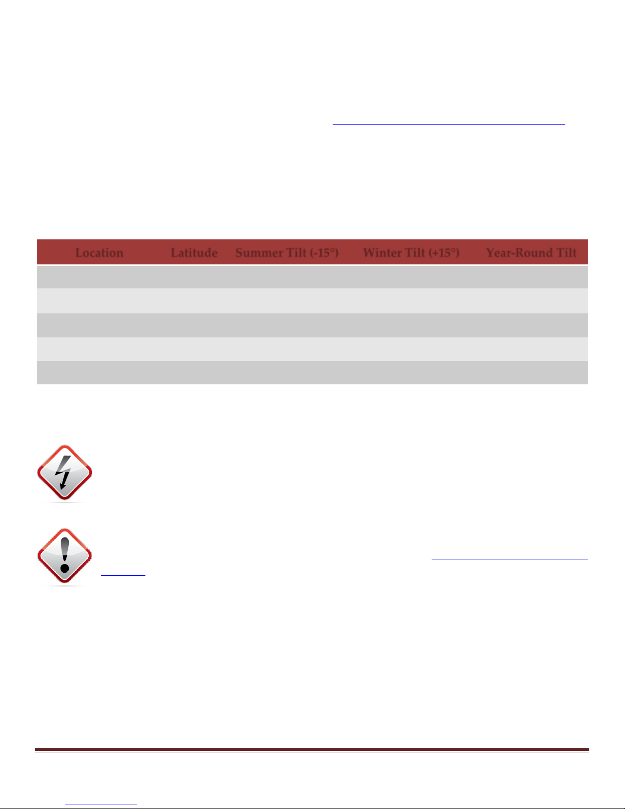
5.6 SEASONAL TILT OF THE SOLAR ARRAY
Location
Latitude
Summer Tilt (-15°)
Winter Tilt (+15°)
Year-Round Tilt
Southern Canada
50°
35°
65°
50°
Upper Third of US
45°
30°
60°
45°
Middle Third of US
40°
25°
55°
40°
Lower Third of US
35°
20°
50°
35°
Central Mexico
20°
5°
35°
20°
The sun is highest in the sky during the summer and lowest in winter. To maximize pumping during
both seasons, adjust the tilt angle periodically. Nearly all currently manufactured mounting racks
can be adjusted. It is sufficient to perform the adjustment only twice per year, at the spring and
autumn equinoxes, to the angles indicated below. See Figure 5-2 Solar Array Tilt Angles by Latitude.
If season adjustments are unwanted or unnecessary, set the tilt angle to the latitude of the pump
location, as a compromise. Do not set the array absolutely horizontal, or dust and debris will
accumulate.
Ideal angles are: Summer optimum = latitude -15° Winter optimum = latitude +15°
FIGURE 5-2 SOLAR ARRAY TILT ANGLES BY LATITUDE
For additional tilt angles not listed, please consult the Mounting Rack Manual or Authorized SunRotor® Dealer
5.7 SOLAR ARRAY WIRING
WARNING: Photovoltaic arrays generate hazardous voltages. A 48 Volt (nominal) array
can generate nearly 100 volts when disconnected from load. All wiring MUST be done
by qualified personnel, in compliance with local, state, and national electrical codes.
To prevent shock hazard while working on array wiring, leave one wire disconnected
between two modules to break the circuit, or cover array to shade it.
ATTENTION: Wiring the panels in the wrong configuration (series or parallel) can damage
the controller. Be certain of the wiring configuration (See Figure 5-3 Solar Panel Wiring
Diagram for examples) prior to connecting the array to the controller. Additionally, it is
recommended to cover or shade the panels when connecting them to the controller. This
prevents electrical discharge from damaging the equipment. Any damage caused by disregarding
these warnings will NOT be covered under the warranty.
If the system uses a single panel, simply plug the MC4 connectors on the solar panel to the male and
female connectors on the controller; however, if more power or voltage is needed to meet the pump
requirements, multiple panels will have to be wired in either series, parallel, or a combined
series/parallel configuration. Examples are provided below to better explain the differences between
parallel and series.
www.sunrotor.com Page 10
Page 12

For these examples, ratings from one of the most common panels will be used. See Figure 5-3 Solar
Panel Wiring Diagram.
195W (24V) Panel Rating – VMP: 38.16 VDC; Voc: 45.36 VDC; I: 5.10 amps
Parallel: Solar panels that are wired in parallel combine their wattage and their amperage, and the
voltage remains the same. In the first example (2 Panels – Parallel) on Figure 5-3 Solar Panel Wiring
Diagram, the positive (+) ends of each panel are connected via a branch connector. The same is done
for the negative (-) ends of each panel. The end of the branch connectors then connect directly to the
MC4 cables that come pre-installed with the controller. Because this is wired in a parallel
configuration, the voltage remains constant at 38 VDC (VMP or average up to 45.36 VDC open
circuit), the watts are doubled to 390W (195W x 2), and a current of 10.20 amps (5.10 amps x 2) is
present. Primarily, this configuration is used to supply more current when the pump requires more
than a single panel can offer. Additionally, adding extra panels in parallel can increase the depth
limit and/or earlier start and later stop times when compared to a single panel system.
Series: Solar panels that are wired in series combine their wattage and voltage, and the amperage
remains constant. This is displayed in the second example (2 Panels – Series) on Figure 5-3 Solar Panel
Wiring Diagram. The positive (+) end of the first panel connects to the controller, while the negative
(-) connects to the positive (+) of the second panel. The second panel’s negative (-) connects to the
controller, completing the circuit. Since this array is wired in series, the voltage doubles to 76 VDC
(VMP or average up to 90.72 VDC open circuit), the watts double to 390W (195W x 2), and the current
remains the same at 5.10 amps. The most common need for this configuration is to power a high
voltage motor.
Series/Parallel: The third example (4 Panels – Series/Parallel) on Figure 5-3 Solar Panel Wiring Diagram
shows TWO PARALLEL STRINGS of TWO PANELS IN SERIES. Each string of two panels in series puts out
76 VDC (VMP or average up to 90.72 VDC open circuit), 390W, and 5.10 amps. The parallel-wired
calculations are 76 VDC (VMP or average up to 90.72 VDC open circuit), 780W, and 10.20 amps. This
configuration is reserved for higher voltage pumps that require more current than a single string of
solar panels wired in series can provide.
Warning: Before connecting any of the cables from the solar array to the controller, be
sure to verify the open circuit voltage does not exceed the voltage limits of the controller
(50/100/200 VDC). Voltages in excess of this maximum will damage the controller. If the
pre-installed MC4 connectors on the controller are removed, be certain that the positive
and negative wires are not crossed when connecting them to the controller. If unsure of the polarity
or voltage, confirm with a voltmeter. Standard SunRotor® controllers have reverse polarity
protection, and will not power up if the polarity is incorrect.
Solar Panels can be wired into the controller in a number of variations to produce the desired
Watt/Voltage/Amperage configuration. Below are examples of the most common 2-4 panel wiring
configurations, including panel arrays configured in series, parallel, and a combination of the two.
Page 11 www.sunrotor.com
Page 13

FIGURE 5-3 SOLAR PANEL WIRING DIAGRAM
5.8 GROUNDING AND LIGHTNING PROTECTION
Lightning can damage solar pump systems if the following precautions are not taken. A proper
connection to ground (earth) is important as it allows static electricity to discharge to earth—helping
to prevent the attraction of lightning. In case of a nearby lightning strike, a well-grounded solar array
support structure provides a path to conduct an induced surge of current around the electrical
circuitry, preventing damage in most cases.
www.sunrotor.com Page 12
Page 14

SunRotor® pump controllers have built-in surge protectors that help to protect them if the controller’s
ground terminal is connected to an effective ground path. Bond the structural components and
electrical enclosures. Interconnect the PV array frames, the mounting rack, and the ground terminals
of all electrical devices, and run the wire to an earth connection. See Figure 5-4 Grounding Diagram.
FIGURE 5-4 GROUNDING DIAGRAM
Page 13 www.sunrotor.com
Page 15

Earth connection: Install a conductive ground path. Use a minimum of one 8-foot copper-plated
ground rod or equivalent, preferably in moist earth. In an area where the earth is very dry (poorly
conductive), it is recommended to bury at least #6 or double #8 (or 10 mm2) bare copper grounding
wire in a trench (perhaps the pipe trench) at least 100 feet (30m) long, with one end connected to the
array structure. Or, cut the ground wire in half and spread it in two directions. A steel well casing
may be used as a ground rod. Drill and tap a hole to make a strong bolted connection to the casing.
The cemented footers of a ground mounted solar array WILL NOT provide adequate electrical
grounding!
Grounding the power circuit?—DO NOT ground either the positive or the negative electrical wires.
The best lightning protection results from grounding the metallic structure only, and letting the
power system “float” ungrounded.
Exception: Connecting the pump to a battery-based home power system that has a negative
ground. If the wiring distance to the pump exceeds 100 feet (particularly in a high lightning
area), or a charge controller that requires negative grounding, DC-rated surge protection devices
are recommended.
Exception: If system grounding is required by the electrical authority in the region, ground the
PV ARRAY’S NEGATIVE wire on the controller, and switch only the positive in the array
disconnect switch (if used). This may increase the risk of lightning damage.
Additional Lightning Protection: Additional grounding measures or protection devices are
recommended in the following instances:
1. Isolated location on high ground in a severe lightning area
2. Very poor grounding potential due to dry, rocky, or otherwise poorly conductive soil
3. Long wire run (more than 100 ft / 30 m) between array and wellhead, or between controller
and remote float switch
DC-rated surge protection devices are available from your Authorized SunRotor® Dealer.
A long run of cable to a float switch can be a source of damaging surges. Shielded, twisted-pair cable
adds considerable protection. Shielded cable has a metallic foil or braid surrounding the two wires.
Ground the shield at the controller end only, not the float switch.
www.sunrotor.com Page 14
Page 16
6 PUMP CONTROLLER INSTALLATION
FIGURE 6-1 SUNROTOR
®
CONTROLLER DESIGN
6.1 PUMP CONTROLLERS & ACCESSORIES
All SunRotor® solar pumps require a SunRotor® controller. The standard SunRotor® controller
features adjustable speed control, low water and tank full sensor connections, linear current boosting
technology, and an adjustable timer that allows well recovery (up to 30 min) after the low water
sensor has been tripped. This feature allows the well to recover properly before beginning to pump
again, saving unnecessary wear and tear on the pump. This model also comes with a hinged, clear
Page 15 www.sunrotor.com
Page 17

door providing easy access to adjust the settings, and the ability to see the indicator lights at a glance.
The controller comes in three sizes: 50V, 100V, and 200V DC input tolerance limits. The size will be
determined by the solar array and pump configuration.
There are other models available that offer fewer features than the standard controller. The overall
function is the same, and the wiring is similar. If any controller other than the SRC-M50T, SRCM100T, or SRC-M200T is purchased, please contact your Authorized SunRotor® Dealer or the
SunRotor® Technical Services Team for any information not provided within this installation guide.
The ability to use both AC (generator, power lines, etc.) and DC (solar array, batteries) is available
with additional equipment. A Power Pack is necessary if both AC and DC input are desired. If a
battery back-up is required for times of need, such as when it is hazy or dark, a charge controller is
needed. No information is provided within this installation guide on configuring and installing these
accessories; however, they may be available on the SunRotor® Solar Products website under the
product information or the Downloads page. If it cannot be found there, please contact the
SunRotor® Technical Services Team at 1(866) 246-7652.
6.2 LOCATING AND MOUNTING THE CONTROLLER
CAUTION: Direct sunlight can reduce the life of the controller.
Mount the controller so it is shaded from the mid-day sun. The easiest location is under the PV array.
If necessary, mount the controller inside a shelter or make a sheet-metal shade for it. If the solar array
is a substantial distance from the wellhead, it is preferable to place the controller closer to the pump.
If the solar array is nearby, it is recommended to mount the controller box to the pipe below the solar
array. Securely fasten the controller to the opposing side of the solar panels. The solar panels will
keep the controller out of the direct sunlight, increasing its efficiency and life. Controller mounting
hardware may be purchased from your Authorized SunRotor® Dealer, or built using materials
commonly available from electrical supply stores.
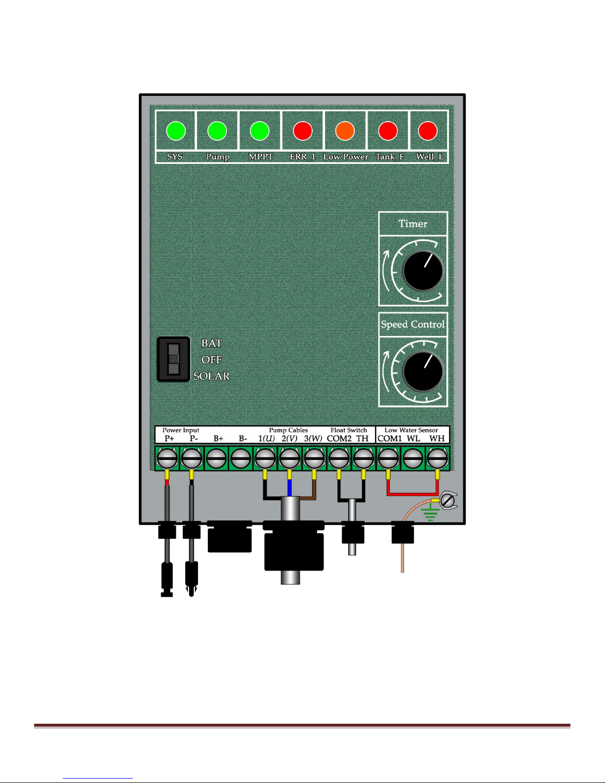
6.3 INDICATOR LIGHTS
The indicator lights located on the upper half of the controller display the status of the pumping
system (See Figure 6-1 SunRotor® Controller Design). Below is an explanation of each indicator light
and its function.
SYS (Solid Green): This indicator light will illuminate whenever the switch is in the on position and
the power is available to the controller.
Pump (Solid Green): This indicates that power is being applied to the pump. This indicator will
illuminate 20-30 seconds after the system has been switched on as long as there is adequate power
available and all water level sensors are reading normal.
www.sunrotor.com Page 16
Page 18

MPPT (Flashing Green): The MPPT (Maximum Power Point Tracking) monitors the power input from
the solar panels and adjusts the voltage and current to gain the highest performance of the pump.
This indicator light will flash green when the MPPT is working properly.
ERR_1 (Solid Red): This light will usually illuminate when there is an overcurrent issue. If the pump
is drawing too high of an amperage, the overcurrent protection will engage to protect the pump,
motor, and controller. The pump will be shut down until the system is reset. It should automatically
start after 20 minutes. If not, cycle the power switch and verify the ERR-1 light has turned off. If it
repeats, call Technical Support. Overcurrent can be caused by pump or motor problems, shorts in the
wiring, or even a blockage in the piping. Please consult your Authorized SunRotor® Dealer for
technical support, or contact SunRotor® Technical Services Team directly at 1(866) 246-7652.
LOW POWER (Solid Orange): This indicator light will illuminate when there is not enough power to
operate the pump or when the pump motor cannot start because of blockage, torn stator, or other
factors. Low sunlight or hazy conditions are usually the cause.
Tank_F (Solid Red): This light indicates the storage tank is full. When water in the tank reaches its
desired level, the float switch rises and closes the circuit. The pump will shut down until the water
level decreases and the remote switch returns back to the open position.
Well_L (Solid or flashing Red): This indicator light is illuminated when the water level in the water
source has dropped below the sensor. When the low water sensor is tripped, the pump is shut down,
and the timer will start as long if it has been set above zero (red light flashes when timing). The
pump will restart when this time expires. The time is adjustable between 0 and 30 minutes.
6.4 REMOTE FLOAT SWITCH
The purpose of a float switch is to turn the pump off when the storage tank fills, and to turn it back
on after the level drops again. The use of a float switch is highly recommended to reduce the running
time and to prevent waste of ground water. It can control the pump from a long distance away as
long as the proper wire is used. Ask your Authorized SunRotor® Dealer about pricing and
applications for float switches.
7 PUMP PREPARATION
7.1 WIRE SIZING
All SunRotor® solar pump systems require a minimum of 10 gauge pump cable, except when the
TDH is greater than 300 ft., in which 8 gauge pump cable is required. It is also recommended that
any and all additional instrument cable not provided with purchased sensors and float switches be a
minimum of 18 gauge shield twisted-pair cable. This will help prevent damage from ambient or
transient lightning strikes. If unsure of the proper wire sizing, contact your Authorized SunRotor®
Dealer or the SunRotor® Technical Services Team at 1(866) 246-7652.
Page 17 www.sunrotor.com
Page 19
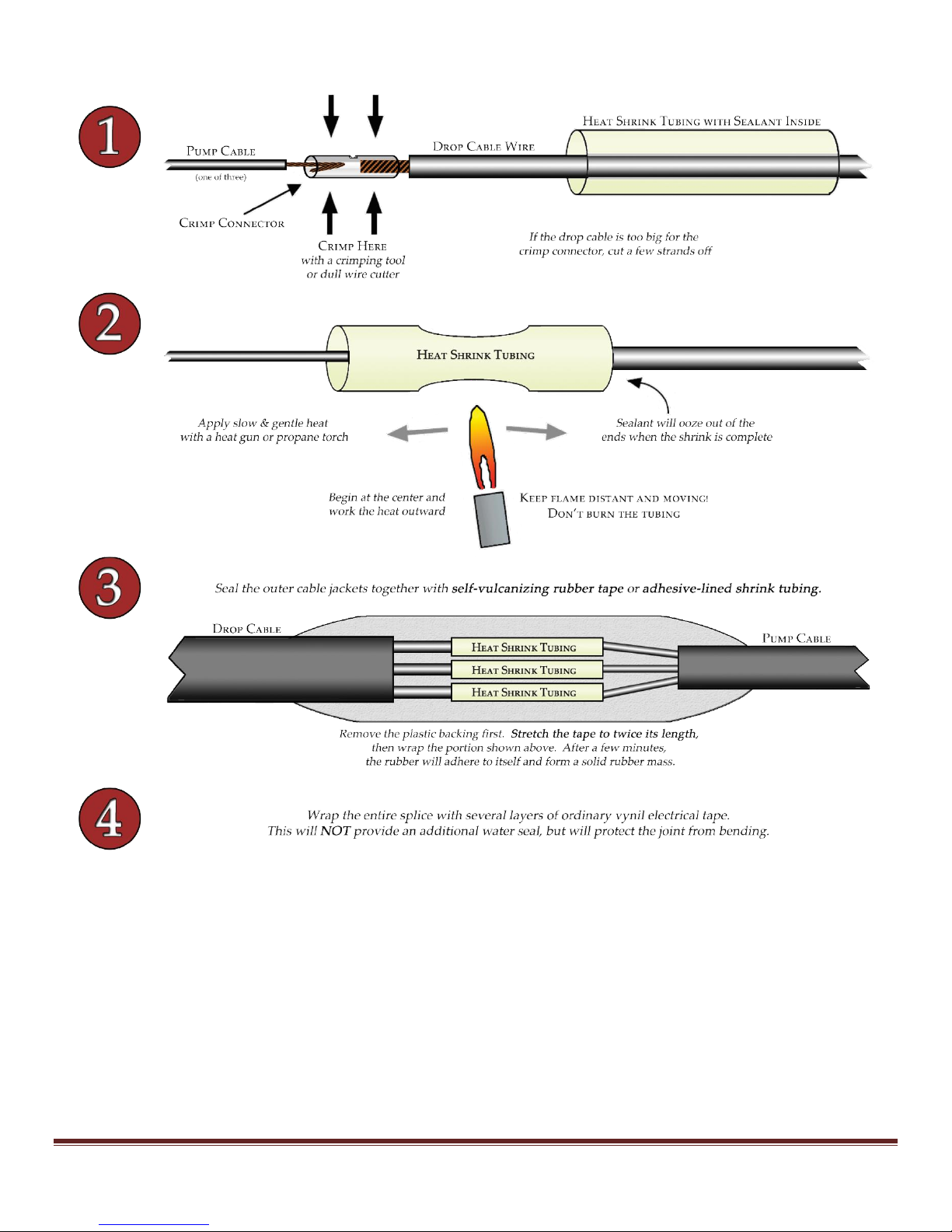
FIGURE 7-1 WIRE SPLICE DIAGRAM
7.2 INSTALLING THE CHECK VALVE
All SunRotor® solar pumps are shipped with a check valve that must be installed prior to setting the
pump. These are used to protect the pump from water pressure driving it in the reverse direction,
which could generate potentially harmful voltage to the controller. Most check valves have an arrow
indicator displaying the direction of flow; make sure the arrow is facing opposite the pump. To
reduce the chances of this valve being installed improperly, it will ship with an all-thread adapter
already mounted. The all-thread will be connected to the pump outlet, whereas the drop pipe fittings
will attach to the other.
www.sunrotor.com Page 18
Page 20

7.3 SPLICING THE WIRES
Properly splicing the pump and sensor wires is a key step during the solar pump installation process.
The recommended process includes the use adhesive-filled heat shrink tubing. After stripping the
ends of the wires, use the provided crimp connectors to merge the two ends. Place both ends into the
heat shrink tubing—and with a standard hot hair heat gun or flame torch—work from the middle
outward to the edges. Adhesive should be oozing from each end of the shrink tubing, ensuring a
proper seal has been made. Be sure to mark or write down the matching cables connections (Black >>
Green; Brown >> Red; etc.). Pull lightly on each corresponding cable after crimping them together to
verify that they are both secure and making a good connection.
ATTENTION: Use caution while heating the shrink tubing. If care is not used, injury may
be sustained by the flame or heated adhesive leaking from the ends. Remember to keep
the heat source moving to avoid burning the tubing or wire insulation. A double
watertight seal must be provided using properly engineered materials to prevent water
from seeping into the pump cable—and possible into the motor. Failure to do so will VOID THE
WARRANTY. See Figure 7-1Wire Splice Diagram.
7.4 SAFETY ROPE
It is recommended that the safety rope be polypropylene or polyethylene water well safety rope. It
can be purchased from your Authorized SunRotor® Dealer or local pump supply store. If
unavailable, use polypropylene marine rope rated for at least 1000 pounds (450 kg). Stainless steel
cable may be used, if preferred.
ATTENTION: DO NOT use nylon rope in water. Nylon absorbs water and softens after 5 to
10 years. Failure may cause damage or loss of equipment. Polypropylene is the accepted
material for water well rope.
7.5 LOW WATER SENSOR
Low water sensors are placed above the pump inside the well. The sensor sends a signal to the
controller that stops the pump when the well’s water level drops below the sensor. This ensures the
pump motor isn’t damaged if the well’s recovery rate is less than the flow rate of the pump.
ATTENTION: It is HIGHLY recommended that all SunRotor® solar pumps are installed with
this sensor. It is an extremely economical and effective method of protecting equipment.
Damage to the equipment from pumping dry is NOT covered under your warranty.
Install the low water sensor 6-18 inches above the pump. Secure it to the drop pipe by using cable
ties around the body of the device. Wrap both the low water sensor body and cable ties with high
quality, waterproof electrical tape. PLEASE NOTE: there are holes at or on the top of the low water
sensor; do NOT cover these holes when securing the device to the drop pipe.
Page 19 www.sunrotor.com
Page 21
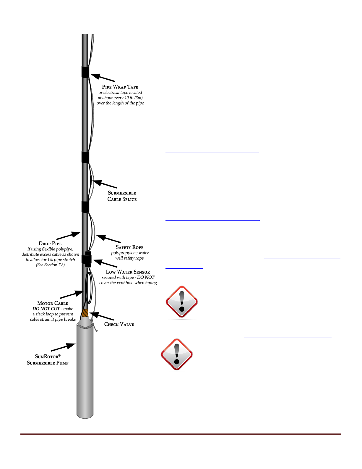
FIGURE 7-2 BINDING DIAGRAM
7.6 FREEZE PROTECTION
In a cold climate, water can freeze in the pipe and block
water flow. This can cause the pipe to burst, or worse,
pump or controller damage. This type of damage is
NOT covered under your warranty.
The use of an anti-freeze bleeder valve is recommended
if installing in climates prone to freezing conditions. In
normal operation, the pressure of the moving water
keeps this valve closed, yet allows for the draining of
water in the lines after your pump stops pumping (See
Figure 4-1 Solar Pump Diagram). Alternatively, the use of
a pitless adapter may be used.
7.7 BINDING PIPE, CABLES, & ROPE
The cables (both the pump and low water sensor) and
the safety rope must be bound to the drop pipe with
tape of an industry-approved (UL-listed) variety. See
Figure 7-2 Binding Diagram. Pipe wrap tape is
recommended. First, wind tape around the pipe, more
than one turn, so that it sticks to itself. Second, wind it
around the cable and rope. This prevents it from
slipping down the pipe. See Section 7.9 Allowance for
Pipe Stretch to determine the amount of additional
lengths of cable and rope needed prior to wrapping.
CAUTION: DO NOT use nylon cable ties in
water. Nylon absorbs water and softens
after 5 to 10 years. Failure may cause
damage or loss of your equipment.
ATTENTION: Figure 7-2 Binding Diagram is
used for illustration purposes ONLY. Be sure
to carefully read through the provided
instructions first, as the illustration may not
be 100% accurate in scale or positioning.
Disregarding this notice may result in damage or loss
of equipment, and is NOT covered under your
warranty.
www.sunrotor.com Page 20
Page 22
7.8 WELLHEAD COMPONENTS
There are a few recommended methods to support the drop pipe. The first is a well seal. This is a
plate that fits on the top of the well casing. It provides a seal against contamination of the well, and it
supports the weight of the in-well assembly. In freezing climates, the wellhead must be located in a
heated building or in a covered well pit if no anti-freeze bleeder valve is used with the well seal.
The other method is the use of a pitless adapter. This is a fitting that allows your buried pipe to pass
through the well casing underground, without the need to build a covered pit. This system is used in
many conventional well systems and is available from local well pump suppliers. A well cap is
needed with this method.
The pitless adapter is ideal for freezing climates. It also provides protection against animals,
children, and vehicles that can damage exposed piping.
CAUTION: The pump must be supported primarily by the drop pipe. The rope serves as a
safety measure in case of pipe breakage. The electrical cable must NEVER support any
weight.
The use of flexible conduit running from the top of the well seal or cap to the controller is
recommended. This will help against contamination and damage from animals. Please inform your
Authorized SunRotor® Dealer if the use of flexible conduit is planned, as additional parts are needed.
7.9 ALLOWANCE FOR PIPE STRETCH
Polyethylene (PE) drop pipe will stretch by about 1% of its original length. Rope will also stretch. To
keep it from bearing much weight, cut your rope 1% longer than the drop pipe.
The pump cable should NEVER BEAR ANY WEIGHT. Prevent this by making the length of your cable (the
portion below the wellhead) 1.5% longer than your drop pipe. DO NOT CUT IT YET—extra length is
needed to make a slack loop at the bottom, and to make connections at the surface. If the pump may
need to be lowered in the future, leave some extra cable rolled up at the wellhead, so no splicing will
be needed later.
WARNING: Never lift the pump by the electrical cable.
7.10 COPING WITH DIRTY WATER CONDITIONS
CAUTION: SunRotor® solar pumps are clean water pumps, and are not meant to tolerate
water with extremely high sand or silt, or a high salinity, without increased wear and
tear. DO NOT use this pump to develop or purge your well. Damage caused by pumping
in such conditions is NOT covered under the warranty.
Page 21 www.sunrotor.com
Page 23

The pump has a good resistance to occasional bits of sand and fine silt that normally occur in a water
well. However, as with any pump, extreme abrasive substances will cause accelerated wear and tear
on the rotor and stator, particularly if the water appears turbid.
To avoid pumping dirty water:
1. Have the water well developed, purged, or otherwise improved by a drilling contractor.
2. Temporarily install a larger AC pump (with a generator if necessary) to pump at a high flow
rate until silt is purged from the well.
If dirty water cannot be avoided:
1. Use a smaller drop pipe (recommended no larger than ¾”) if or when possible. This will
maximize the velocity of water flow to allow particles to rise and leave the drop pipe.
2. In case of a drilled well, place the pump as high as possible in the well. If the pump can be
placed higher than the perforations in the well casing, then all but the finest silt will probably
be avoided.
3. Inspect and replace parts periodically (See Section 11 Maintenance).
4. Monitor the situation by observing the accumulation of sediment in the storage tank.
7.11 WATER SANITIZATION
If the well water will be used for household consumption, sanitize the well prior to pump
installation. This can be done with chlorine bleach or a dry chlorine compound poured down the
well just before (or just after) a pump is installed. Consult a local supplier or environmental health
authority for a recommended procedure.
8 PUMP INSTALLATION
8.1 ASSEMBLING THE DROP PIPE, CABLES, AND SAFETY ROPE
Tie the rope underneath the well seal or well cap. If the well cap does not have a place for a rope,
drill a hole in the casing and install an eye bolt. Prepare this detail BEFORE installation of the pump!
Do not leave the rope exposed to sunlight, as it can damage the outside of the casing.
When tying the rope to the pump, it’s important to make a knot that will not slip under tension (a
double half-hitch knot is recommended). If unsure of how to properly secure the pump to the rope,
please use the following method: before passing the rope through the eyelets, make a simple loop
knot 3 or 4 feet from the end of the rope, leaving it loose. Now pass the rope through the eyelets and
bring the end back up. Feed it up through the loop knot so that it doubles the loop and pull the knot
tight—it should feel secure with no tendency to slip.
8.2 MACHINE INSTALLATION
If professionally equipped to install conventional AC submersible pumps, the same equipment can be
used for SunRotor® solar pumps. This method is used primarily for pumps with a set depth of 150 ft
www.sunrotor.com Page 22
Page 24

or more. If setting the pump less than 150 ft, consider using the Hand Installation (See Section 8.3
Hand Installation). It may take less time to drop or pull the pump by hand than it does to use a pump
service truck, especially in a difficult location.
8.3 HAND INSTALLATION
WARNING: Hand Installation can be hazardous. There are potential hazards in handling
any heavy mechanical assembly. If there are any doubts about the ability to SAFELY install
by hand, please hire a professional pump installer. Any injury or damage sustained by
using this method will be the sole responsibility of the installer.
CAUTION: DO NOT use a winch to install or remove the pump. To remove the pump, pull
up the rope, cable, and pipe simultaneously; otherwise, there is a risk of having the
flexible pipe and cables sag down and jam between the pump and casing. This can cause
damage or loss of equipment, and potentially, even the loss of the well itself.
CAUTION: DO NOT use a vehicle to pull the pump. To remove a pump installed by hand,
use HAND POWER only! During removal, the pump can catch on joints or edges in the
casing. Any problems along the way will be felt as you pull by hand. Any damage for
neglecting these warnings will void the warranty.
Lay a barrel (metal oil drum or similar rounded object) next to the wellhead. Run the pipe, cable, and
rope over the round surface, to ease the downward bend and to prevent scraping against the edge of
the casing. Wear leather gloves.
Lower the pump slowly and carefully. To verify the static water level, assign a helper to listen
carefully for a splash as the pump hits the water. You can then determine the static level by
measuring the length of remaining pipe above ground.
The in-well assembly should hang with the weight on the pipe. Tie the rope securely, inside the
casing. Do not attach the rope to the removable cap of the casing, or it will prevent easy removal.
CAUTION: Do not support or pull the pump by the safety rope alone.
Pulling only the rope can cause the cable and pipe to sag and to jam in the casing. It must
be grabbed by the pipe and cable along with the rope. Wear tough leather work gloves.
8.4 RUNNING THE CABLES
Run the pump and low water sensor cables through well seal assembly to the specified grommets on
the bottom of the controller (See Figure 6-1 SunRotor® Controller Design).
If using flexible conduit, attach one end to the top of the well seal assembly and run the wires though
it. Place the connector on the controller side of the flexible conduit and run the cable trough and into
the controller and attach the connector to the controller.
Page 23 www.sunrotor.com
Page 25

9 WIRING THE SYSTEM
9.1 ELECTRICAL WARNINGS
ATTENTION: Wiring the panels in the wrong configuration (series or parallel) can send
excessive voltage and damage the controller. Be confident in understanding the system’s
wiring configuration and voltage limitations (See Figure 5-3 Solar Panel Wiring Diagram for
examples) prior to connecting the solar array to the controller. Additionally, it is
recommended that the panels are covered or shaded when connecting them to the
controller to prevent damaging the equipment. Any damage caused by ignoring these
warnings will not be covered under the warranty.
WARNING: There are live electrical currents with high voltages present that can cause
SERIOUS INJURY OR DEATH. Please use extra precautions and thoroughly read through this
section prior to wiring the system. Follow all appropriate electrical codes. If unsure, hire
a professional. Solar Power & Pump Company is not liable for personal injury or damage
to the equipment.
Please read through this entire section prior to wiring the system. If any questions or concerns on
safety or correct wiring are present this process, please contact your Authorized SunRotor® Dealer or
the SunRotor® Technical Services Team at 1(866) 246-7652.
9.2 WIRING THE CONTROLLER
Run the pump and sensor cables through the bottom of the controller. The use of spade connectors at
the end of your wires is recommended for easy maintenance and repairs in the future.
ATTENTION: Installing a low water sensor is HIGHLY recommended. This device sends a
signal to the controller—which in turn shuts the pump off—if water in the well drops
below the sensor set depth. This protects the pump from running dry.
As shown in Figure 9-1 SunRotor® Pump Controller Wiring Diagram, attach the two wires to
the COM1 and WH terminals. If no low water sensor is used, a jumper is required for the pump to
run.
Wire or cable used for connecting the Tank Full Switch should be two-conductor shielded
instrumentation cable. The use of this cable helps prevent potential lightning damage normally
associated with a lengthy string of cable. Additionally, a ground wire is included in this type of
cable. Similar to the low water sensor, the wires need to be attached to COM2 and TH terminals.
The ground wire should be attached to the nearest back plate mounting screw (See Figure 9-1
SunRotor® Pump Controller Wiring Diagram).
www.sunrotor.com Page 24
Page 26
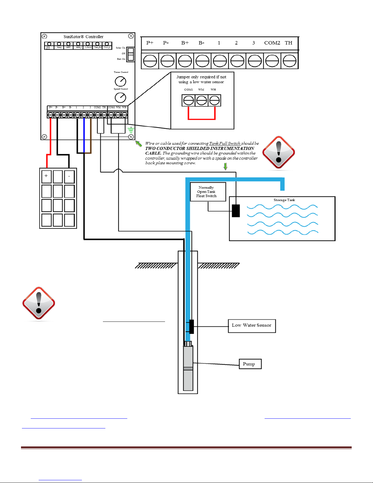
FIGURE 9-1 SUNROTOR
SunRotor® Submersible pumps have a
strict submergence limit of 100 FT.
Exceeding this depth could damage the
pump and will VOID THE WARRANTY.
®
PUMP CONTROLLER WIRING DIAGRAM
Wire the pump cable into the controller. If the corresponding wires were written down as suggested
in Section 7.2 Splicing Your Wires, attach them accordingly; otherwise, use Figure 9-1 SunRotor® Pump
Controller Wiring Diagram to wire the pump properly (typically terminal 1: black; terminal 2: blue;
terminal 3: brown on most SunRotor® model solar pumps). If unsure, attach the pump wires to any
Page 25 www.sunrotor.com
Page 27

of the numbered terminals, and power up the controller to test the pump direction. If no water is
pumped, or if there is suction on the outlet pipe (this only applies to helical rotor pumps—centrifugal
pumps will produce about ¼th flow rate), turn off the power and switch any two of the three pump
cable wires. This will reverse the pump rotation. Turn the pump back on, and confirm water flows
at the proper rate from the pipe. If no water flows after switching two wires, turn the power off and
contact either your Authorized SunRotor® Dealer or the SunRotor® Technical Services Team at 1(866)
246-7652.
9.3 WIRING POWER TO THE CONTROLLER
The SunRotor® controller comes equipped with MC-4 cable connectors already attached to the proper
controller terminals. Ensure the solar array wiring configuration and voltage before attaching the
connectors (See Figure 5-3 Solar Panel Wiring Diagram). Make sure the controller is set to the OFF
position and plug the corresponding female and male ends together.
9.4 POST-INSTALLATION TESTING
The following tests are recommended after completing the installation.
To test the low water sensor, disconnect one wire to open the circuit. Since it is a normally closed
switch, removing one end of the sensor cable or jumper will trigger the circuit logic to turn off the
pump. To test the timer function, set the timer to a low setting: somewhere between 0 and 5 (around
2 ½ minutes). Disconnect the cable and wait for the pump to turn off. After the pump stops,
reconnect the cable. The pump should automatically turn back on after the specified time has passed.
Most tank full float switches are normally open. To test it, jumper between the two tank full
terminals. This will create a closed circuit, and the pump should turn off. Once the jumper is
removed, the pump will restart.
If these tests do not produce the same results, see Section 10 Troubleshooting. Please contact your
Authorized SunRotor® Dealer or the SunRotor® Technical Service Team directly at 1(866) 246-7652 if
any further information is needed.
10 TROUBLESHOOTING
10.1 IF THE PUMP DOESN’T RUN
Most problems are caused by incorrect connections (in a new installation) or bad splices on the pump
cable or low water sensor. The SYSTEM light will indicate that the system is switched on. It
indicates that VOLTAGE is present, but there may not be sufficient power to start the pump.
System appears dead, no lights showing on the controller:
1. Is there a disconnect switch or circuit breaker installed on the solar array circuit? Is it off?
2. Look for disconnected or damaged wires.
3. Is there any dust or debris on your solar array?
www.sunrotor.com Page 26
Page 28

Pump attempts to start every 60-90 seconds but doesn’t run:
1. There may be insufficient power reaching the controller. A solar-direct system should start if
there is enough sun to cast a slight shadow.
2. If the pump was recently connected (or reconnected) to the controller, it may be running in the
opposite direction due to a wiring error. See Section 9.2 Wiring the Controller.
3. The pump or pipe may be packed with mud, sediment, or debris.
4. Helical rotor models: The rubber stator may be expanded from heat, due to sun exposure or
pump water that is warmer than 100°F (38°C). This may stop the pump temporarily, but will
not cause damage.
10.2 INSPECT THE SYSTEM
Many problems can be located by a simple inspection. No electrical experience is required for this.
Inspect the Solar Array
1. Is it facing the sun? (See Section 5.3 Solar Orientation).
2. Is there a partial shadow on the array? If only 10% of the array is shadowed, it can potentially
stop the pump.
Inspect All Wires and Connections
1. Look carefully for improper wiring (especially in a new installation).
2. Make a visual inspection of the condition of the wires and connections. Wires are often
chewed by animals if they are not enclosed in conduit or buried.
Inspect the Controller
1. Open the clear hinged door to have an unobstructed view of the terminal strip and circuit
board.
2. First, check for a burnt smell. This will indicate a failure of the electronics. Look for burnt
wires, bits of black debris, and any other signs of lightning or other electrical damage.
3. Inspect the grounding wires and connections. Most controller failures are caused by an
induced surge from nearby lightning where the system is NOT effectively grounded.
Grounded connections must be properly made, tight, and free of corrosion (See Section 5.8
Grounding and Lightning Protection).
Check the Low Water Sensor (See Section 7.5 Low Water Sensor)
If the controller indicates LOW WATER (Well_L indicator light is solid red) when the pump is in the
water, inspect the low-water sensor. The sensor should have been mounted on the drop pipe above
the pump. If inspection is not feasible, bypass the sensor or test it electronically.
1. If the sensor is NOT being used, there must be a wire used to jumper the COM1 and WH
terminals.
2. The sensor must be mounted vertically (within about 10°).
Page 27 www.sunrotor.com
Page 29

3. The sensor or its wires may be broken. Inspect the wires for damage.
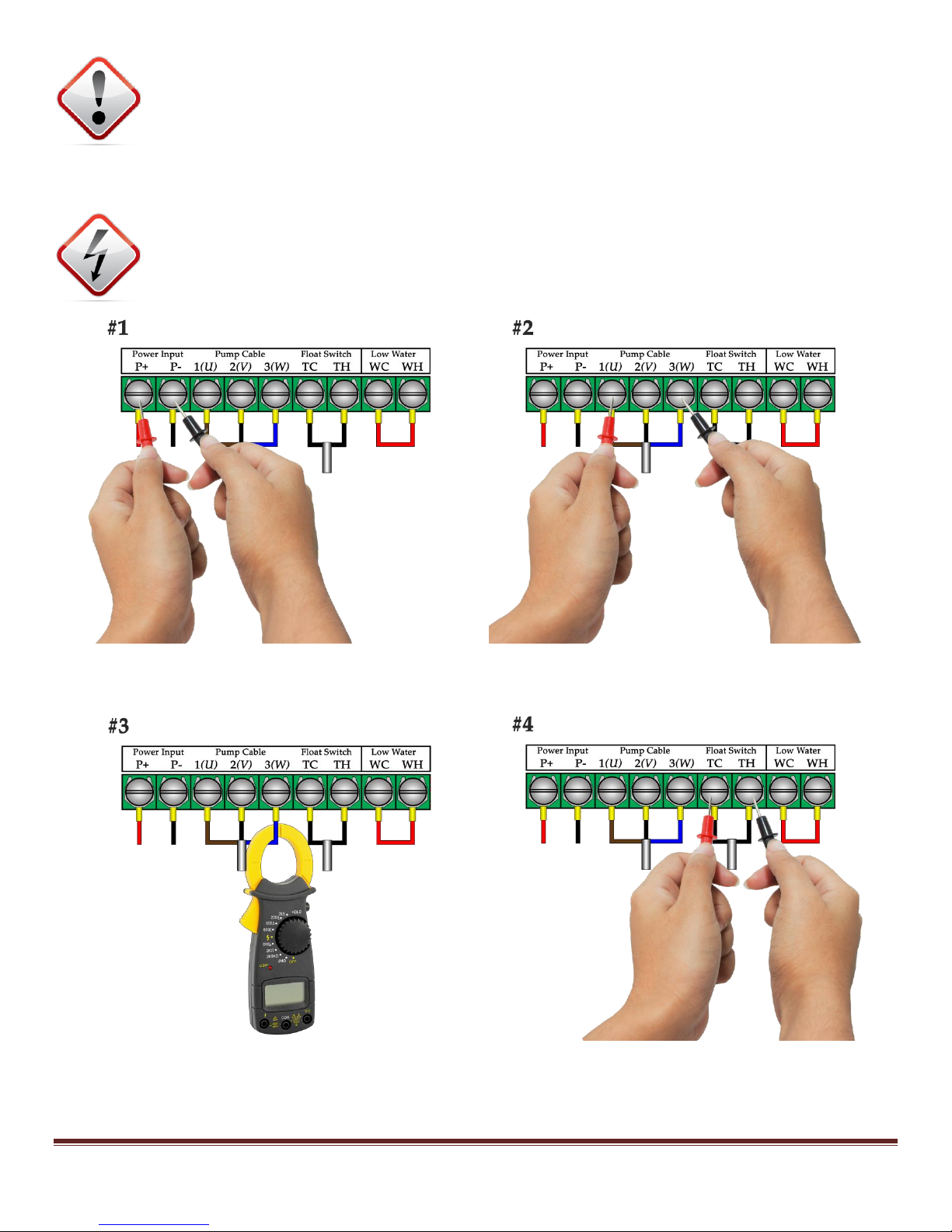
Test/Photo
Number
Test
Description
Notes
Meter
Setting
Probe
Input +
Interpretation
1A
PV (solar) array
open-circuit voltage
Switch the controller to
the OFF position
DC volts
V …
Reading should reflect the VOC
value on the panel label
1B
DC input voltage
during pumping
Switch the controller to
The ON position
DC volts
V …
Indicates proper
controller input function
2A
Pump AC voltage
during pumping
Read any two of the pump cable
wires (1, 2, 3)
AC volts
V …
Voltage determines speed, and
assures that the motor
is spinning
2B
Pump circuit
resistance
Power OFF
Measure ALL 3 pump wires
(1-2 / 1-3 / 2-3)
Ohms
Ω
Ω ...
Normal (0.6 – 1.4) and equal means
the motor, cable, and
splices are all good
3
Motor AC current
draw
Measure any one of the three pump
cable wires
AC amps
AMPS 1A
or higher
Current is proportional
to the torque
load on the motor
4
Resistance between
float switch wires
Check both open and closed circuit
resistances
Ohms
Ω
Ω ...
If there is any resistance other than
0 or ∞, your Tank Full may trip,
causing unwanted stopping of
pump
4. If the pump can run when the sensor is OUT of the water, the float in the sensor is stuck. In
surface water, this can happen from algae, small insects or snails, or other debris.
Check the Tank-Full Float
If the Tank_F indicator light is red when the storage tank is not full, the float switch may be
damaged. Inspect the tank full float switch. It should be mounted to the side of the storage tank
unless a tethered float switch is used, in which case you can find it by following the float switch cable
down to the weight. If inspection is not feasible, bypass the switch or test it electronically.
10.3 ELECTRICAL TESTING
There are several tests that can be performed with a mutlimeter to determine why the solar water
pumping system has failed. Figure 10-1 Electrical Testing will provide you with what settings and
terminals to check. Reference the corresponding images for clarification.
Probe input: Some meters give a choice of probe sockets. The black negative (-) probe ALWAYS goes
in the “COM” (common) socket. The red positive (+) probe varies, and is specified below on each of
the tests.
FIGURE 10-1 ELECTRICAL TESTING
www.sunrotor.com Page 28
Page 30
ATTENTION: To measure voltage, the red positive (+) probe needs to be placed in the
VOLTS socket on the meter. If it is in the AMPS socket, attempting a voltage reading will
cause a short circuit and can damage the equipment.
Access: Open the controller cover to access the terminals. The appearance of the terminals and/or
wiring may vary.
WARNING: These tests pose potential shock and burn hazards to both equipment and
person. Follow appropriate safety precautions. If unsure, hire a professional. Solar
Power & Pump Company is not liable for personal injury or damage to equipment.
Page 29 www.sunrotor.com
Page 31

10.4 TROUBLESHOOTING CHECKLIST
The following items may be causing the solar water pumping system to have less than expected flow
rate or pump failure. Be sure to go through the list before contacting your Authorized SunRotor®
Dealer or calling the SunRotor® Technical Services Team.
1. Is the solar array receiving shadow-free light? It only takes a small shadow to reduce
efficiency. Is the solar array oriented properly toward the south, and tilted at the proper
angle? See Section 5 Solar Array Installation.
2. Has any additional lift or pressure requirements been added or changed? The system was
sized based on specific information provided; if this is changed, there may be a reduction in
flow rate.
3. Are the wires and pipes undersized? If the pump wires and pipe were not adequately sized
for the distances used, the flow rate may not be consistent due to loss in current and/or friction
loss.
4. Inspect and test the solar array input and controller output. Are the values lower than what
the system is rated for? This may be caused by a short in the wire, bad connection or
improperly configured wiring.
5. Are there any leaks in the pipe from the pump? There should be little or no leakage over a
period of hours.
6. Has the pump’s speed control setting been moved lower than the maximum? The speed
control can slow the pump down to 30% of maximum power, and may be causing lower than
expected flow rates if moved.
7. Look in the water tank or pipes:
a. Is the AC motor current lower than normal? The rotor and/or stator may have been
worn from too much abrasive materials or particles (sand or clay) in the water. See
Section 11 Maintenance for more details on how to change the rotor/stator.
b. Is the AC motor current higher than normal? Does it have trouble starting in low light?
This is likely related to a blockage in the pump and/or pipe.
c. Is there sediment accumulating in the pipes or tank? Additional accessories may be
needed to keep from damaging the system (See Section 7.10 Coping with Dirty Water
Conditions).
Additionally, age may be a factor. After many years of use, it may be necessary to have the motor
rebuilt or replace the pump end. For more information and services provided, please contact the
SunRotor® Technical Services Team.
11 MAINTENANCE
One of the defining features of the SunRotor® solar pump product line is its ability to be repaired at a
fraction of the cost of buying a new replacement. A little care and attention can extend the life of the
system drastically and save money in the long run.
www.sunrotor.com Page 30
Page 32
WARNING: The power should be turned OFF, as well as the pump wires removed, prior
to performing any maintenance on the pump or other equipment. Disregarding this
warning may lead to DEATH or SERIOUS INJURY. Follow any and all local, state, and
federal electrical standards and procedures and use caution.
11.1 HELICAL ROTOR PUMP END MAINTENANCE
The helical rotor pump line offers one of the easiest procedures for maintaining water demands. In
locations where abrasive minerals or sediments reside in the water source, both the rotor and stator
can eventually wear down, which in turn decreases the flow rate of the system. To replace these
parts, the pump will first need to be pulled from the well. Before starting any service, please turn off
the controller and disconnect the pump wires to prevent any high voltage current from causing
injury or death.
After the pump has been pulled from the well, begin dismantling the pump end. First, take off the
filter screen by removing the screws holding it secure to the pump. Next, remove the three (four on
some models) bolts holding the cast pump end in place. Once removed, access to the stator will be
available. Pull the worn stator from the rotor. Inspect the rotor for damage. If the rotor is
undamaged push a new stator on and replace the pumps end.
If the rotor is damaged, remove the three (four) bolts from the motor and remove the pump housing.
Remove the setscrews in the motor coupler (rubber piece) and unscrew the rotor from the motor shaft
(counter threaded, turn clockwise to remove). Install the new rotor and replace the setscrews in both
ends of the rubber coupling. Re-attach the pump housing, install the stator and then the pump end.
Finish with reinstalling the filter screen. In most circumstances, this will be all that is necessary to
regain the original flow rates. Set the pump back as it was in the initial installation. Once everything
is back in place, turn the pump on and observe the flow rate. There should be an observable increase
if the worn rotor/stator was the only underlying fault in the system.
11.2 CENTRIFUGAL PUMP END MAINTENANCE
Centrifugal pump ends currently do not offer the same convenience of field repair as the helical rotor
pump ends. Contact your Authorized SunRotor® Dealer or the SunRotor® Technical Services Team
for more information.
11.3 PUMP MOTOR REPAIR
All of the SunRotor® solar pumps—with the exception of the SR-26—have repairable pump motors.
Winding damage on the motor is currently unrepairable. If the pump motor is found to be the cause
of the system failure, contact the SunRotor® Technical Services Team for available rebuild options.
11.4 SOLAR PANEL MAINTENANCE
Depending on the region the system is installed, a few key procedures will help in maintaining the
required water demand. Many solar pump installations will be located in fields and other rural
areas, prone to the elements and dirt blown by the wind. If accessible, wipe or hose down the solar
Page 31 www.sunrotor.com
Page 33

panel array occasionally to prevent dust and debris build-up on the solar array. This will ensure the
system is being provided with all of the available power produced by the panels.
11.5 MISCELLANEOUS
Debris, livestock, insects, and other creatures can cause the system to run at less than optimal speeds.
When available, check wires, cables, pipes, and hose for damage caused by any number of
environmental circumstances. A few minutes to give the system a once-over can extend the life of the
solar water pumping system.
11.6 REPAIRS AND REPLACEMENTS
In the event that the pump needs to be repaired and/or replaced, contact the SunRotor® Technical
Services Team at 1(866) 246-7652 or 1(580) 303-4015. You will be provided with an RMA number.
ATTENTION: DO NOT send any equipment back to SunRotor® Solar Products without an
RMA. Your equipment may be lost or mishandled without the proper identification.
Detailed instructions will be provided upon contact. If required to send the pump back for repair or
replacement, please cut the pump cable above the splice (on the controller side). Including the splice
helps to determine the cause of the pump failure.
In the case of controller failure, return only the circuit board, not the enclosure. Remove the four (4)
screws holding the aluminum backplate to the enclosure. Return only the circuit board and
backplate.
For all other parts and accessories, contact the SunRotor® Technical Services Team.
www.sunrotor.com Page 32
Page 34

12 ABOUT SOLAR POWER & PUMP COMPANY
Solar Power & Pump Company, located in Elk City, OK, was founded in 1998 by CEO/Owner Dennis
Austin. Dennis graduated from SWOSU in Weatherford, OK with a B.S. in Industrial Technology.
He spent many years working all over the United States building advanced systems including, but
not limited to, remediation equipment, pumps and controllers, emergency power systems, as well as
programming automated systems and controls. Eventually, he moved back to western Oklahoma
and his family roots, and began selling and installing solar water pumping systems. Noticing some
trends and possible positive changes within the machinery and design of the current systems out
there, he decided to branch out and have his own solar submersible pump designs manufactured.
In 2008, SunRotor® Solar Products was born. Using knowledge gained from throughout his career,
paired with the knowledge passed along from family in the water business, the first highly efficient
and affordable SunRotor® solar pump was introduced to the market. Since then, more models have
been added, as well as new features, with new and innovative designs and functions planned for the
future.
In late 2013, Solar Power & Pump Company expanded once again, this time purchasing a well-known
and established solar surface pump line, Dankoff Solar out of Santa Fe, NM. Dankoff Solar has been
offering solutions for solar surface water pumping applications for 36 years, and perfectly
complements the SunRotor® solar submersible pump product line. Pairing the two products, many
of our customers are finding new and inventive ways to meet any number of water demand
applications.
It is the goal of Solar Power & Pump Company to not only bring the most efficient and cost effective
products to the market, but to continue to grow the industry. Currently, there is new technology
being developed, with hopes of changing how the world meets their water delivery needs.
One of the biggest factors in Solar Power & Pump Company’s success has been its growing dealer
base. Their eager willingness to provide the highest level of customer service has been without a
doubt pivotal to the company’s continued growth and success. These values and work ethic, which
are well known in the South or any small farming community, have expanded well beyond the
region, and are now experienced throughout the global market in a manner that makes us all proud.
Last, but certainly not least, thanks need to be given to the loyal Solar Power & Pump Company
customers. Through their patience and understanding, a wonderful partnership has been formed,
and their word of mouth has been some of the best advertising ever experienced. For that, thanks
alone could never be enough. It is the hopes and dreams of Solar Power & Pump Company that all
the work put into new product development, as well as continuing to make the current products both
more efficient and cost effective, will show our vast gratitude. Please never hesitate to contact us by
any form, be it phone, e-mail, or website submission for any number of reasons—product inquiry,
suggestions, etc. Thank you again.
SunRotor® Solar Products Team
Page 33 www.sunrotor.com
Page 35

13 ADDITIONAL INFORMATION
Solar Power & Pump Company prides itself on offering each and every customer with easy access to
as much information as needed—no matter the reason or motivation. Below are some additional
links that may be of use.
SunRotor
®
Downloads and Resources—all of the products’ spec sheets, warranty, and other
educational documents are available here
https://www.sunrotor.com/downloads
SunRotor
®
Warranty Registration—visit this page to register your solar pumping system
https://www.sunrotor.com/warranty-registration
SunRotor
®
Renewable Energy Incentives—find all of the important tax deductions available
when using a solar powered water pumping system
https://www.sunrotor.com/incentives
Solar Power & Pump Company: Why Go Solar?—a small breakdown of the benefits of using
solar power over its alternatives when it comes to water pumping
http://www.solarpowerandpump.com/why-go-solar
Database of State Incentives for Renewables & Efficiency—another site very useful in trying to
maximize your savings
http://www.dsireusa.org
Renewable Energy World - Solar Energy & News—a reliable source for news on the solar
energy industry
http://www.renewableenergyworld.com/rea/home/solar-energy
National Renewable Energy Laboratory— the U.S. Department of Energy's primary national
laboratory for renewable energy and energy efficiency research and development
http://www.nrel.gov
Solar Energy Industries Association (SEIA)—home of the national trade association for solar
energy
http://www.seia.org
U.S. Department of Energy—learn more of what the United States’ policies are when
pertaining to solar and other renewable energies
http://www.energy.gov
Dankoff Solar Resources—as a division of Solar Power & Pump Company, Dankoff Solar has
several helpful documents available to help you better understand solar water pumping
http://www.dankoffsolarpumps.com/resources
© Copyright 2014 – Solar Power & Pump Company, LLC. All Rights Reserved.
www.sunrotor.com Page 34
Page 36

 Loading...