

Page 1

SECTION
Quickie®Pulse
6BC, 6SC, 6CC, 5BC, 5CC, 6MPC
Supplier:
User:
This manual must be given to the rider of
this wheelchair.
Before using this wheelchair read this entire manual and save
for future reference.
Quickie®Pulse
6BC, 6SC, 6CC, 5BC, 5CC, 6MPC
ENG L ISH
PULSE
O w n e r ’ s M a n u a l
Distribuidor:
Pasajero:
Cada una de las sillas se envía con un manual de instrucciones en inglés. El manual en español
o francés está disponible en formato PDF en nuestra página en Internet:
www.SunriseMedical.com. Ingrese a la página del producto específico para descargar el manual, o comuníquese con el proveedor autorizado de Sunrise Medical.
Este manual debe ser entregado al pasajero de esta silla de
ruedas.
Antes de usar esta silla de ruedas, lea este manual en su
totalidad y guárdelo para futura referencia.
Quickie®Pulse
6BC, 6SC, 6CC, 5BC, 5CC, 6MPC
Fournisseur:
Utilisateur / Utilisatrice:
Chaque fauteuil est livré avec un manuel d’instructions en anglais. Les versions en espagnol et
en francais sont à ançais est à votre disposition en format PDF sur le site:
www.SunriseMedical.com. Veuillez vous rendre à la page de votre produit pour télécharger
le manuel dans la langue souhaitée, ou contactez un fournisseur agréé Sunrise Medical.
Ce manuel doit être remis à l’utilisateur / utilisatrice de ce
fauteuil roulant.
Avant d’utiliser ce fauteuil roulant, lisez entièrement ce manuel et conservez le pour le consulter ultérieurement.
M a n u a l d e I n s t r u c c i o n e s
M o d e d ’ e m p l o i
Page 2

QUI CK IE PU LS E
I. INTRODUCTION
SUNRISE LISTENS
Thank you for choosing a Quickie wheelchair. We want to hear
your questions or comments about this manual, the safety and
reliability of your chair, and the service you receive from your
Sunrise supplier. Please feel free to write or call us at the address
and telephone number below:
Sunrise Medical (US) LLC
ustomer Service Department
C
2842 Business Park Ave
Fresno, CA 93727
(800) 333-4000
FOR ANSWERS TO YOUR QUESTIONS
Your authorized supplier knows your wheelchair best, and can
answer most of your questions about chair safety, use and maintenance. For future reference, fill in the following:
upplier: _______________________________________________________________
S
Address: _______________________________________________________________
______________________________________________________________________
USER WARNING
WARNING
Attention wheelchair users, do not operate this wheelchair without first reading the owner’s manual. If you do not understand the
instructions and warnings of this owner’s manual please contact
your dealer or qualified technician before operating this Quickie
wheelchair. Failure to do so may result in damage and/or injury.
DEALER/TECHNICIAN WARNING
WARNING
Attention dealers and qualified technicians, do not operate or service this wheelchair without first reading this owners manual. If you
do not understand the instructions and warnings of this owners
manual please contact the Quickie Technical Service Department
before operating and/or servicing this Quickie wheelchair. Failure
to do so may result in damage and/or injury.
ELECTROSTATIC DISCHARGE
WARNING
Telephone: _____________________________________________________________
Serial #: _________________________________________ Date/Purchased:_________
INFORMATION YOU SHOULD KNOW
No component of this chair was made with Natural Rubber Latex.
DISPOSAL AND RECYCLING INFORMATION
When this product reaches the end of its life, please take it to an
approved collection or recycling point designated by your local or
state government. This wheelchair is manufactured using a variety
of materials. Your product should not be disposed of as ordinary
household waste. You should dispose of your wheelchair properly, according to local laws and regulations. Most materials that are
used in the construction of this product are fully recyclable. The
separate collection and recycling of your product at the time of
disposal will help conserve natural resources and ensure that it is
disposed in a manner that protects the environment.
Ensure you are the legal owner of the product prior to arranging
for the product disposal in accordance with the above recommendations.
Power wheelchairs have printed circuit boards. Careful attention
should be given to printed circuit board handling techniques to
avoid damaging the control, and/or drive electronics of the chair,
this could create a safety hazard. Do not expose or remove printed circuit boards. Contact your Authorized Dealer for help with
any electronics issues.
Related Documents
Listed below are additional documents which are referenced in
this owners manual.
• RNET Owners Manual:
PG Drives Technology CJSM2 Installation manual
• RNET OBP Owners Manual
• RNET Omni Owners Manual
• PULSE Service Manual
119832Rev. G
2
Page 3

QUI CK IE PU LS E
II. TABLE OF CONTENTS
I.INTRODUCTION .....................................................................................2
III. YOUR CHAIR AND ITS PARTS ................................................4
IV. NOTICE– READ BEFORE USE...................................................5
V. EMI (ELECTROMAGNETIC INTERFERENCE).......................5
A.What is EMI?................................................................................5
B. What effect can EMI have?.......................................................5
C.Sources of EMI ........................................................................5-6
D.Distance from the Source ........................................................6
E. Immunity Level ............................................................................6
F. Report all Suspected EMI Incidents........................................6
G.EMI from Chair ...........................................................................6
H.Head Array Safety and RFI.......................................................6
VI. GENERAL WARNINGS................................................................7
A.Notice to User and Attendants..............................................7
B. Weight Limit................................................................................7
C.Controller Settings.....................................................................7
D.Safety Checklist ...........................................................................7
E. Changes and Adjustments ........................................................7
F. Accessories ..................................................................................7
G.When Seated in a Parked Wheelchair ..................................8
H.Environmental Conditions........................................................8
I. Terrain ..........................................................................................8
J. Street Use ....................................................................................8
K. Motor Vehicle Safety .................................................................8
L. Center of Balance.......................................................................8
M. Transfers .....................................................................................9
N.Reaching or Leaning ...................................................................9
O.Dressing or Changing Clothes................................................9
P. Obstacles......................................................................................9
Q.Driving in Reverse......................................................................9
R. Ramps, Slopes, and Sidehills.....................................................9
S. Reduce the Risk of a Fall, Tip-over or Loss of Control ..10
T. Ramps at Home and Work ...................................................10
U.Wheel Chair Lifts .....................................................................10
V. Curbs and Single Steps............................................................10
W. Stairs .........................................................................................10
X.Escalators ...................................................................................10
VII. WARNINGS: COMPONENTS AND OPTIONS.................11
A.Armrests.....................................................................................11
B. Batteries .....................................................................................11
C.Cushions and Sling Seats ........................................................11
D.Fasteners ....................................................................................11
E. Footplate, and Footrests ........................................................11
F. Motor Locks ..............................................................................11
G.ON/OFF Switch ........................................................................11
H.Pneumatic Tires........................................................................11
I. Positioning Belts .......................................................................11
J. Push Handles .............................................................................12
K. Seating Systems.........................................................................12
L. Upholstery Fabric.....................................................................12
M.Suspension..................................................................................12
N.Wiring .........................................................................................12
O.Assignable Controls.................................................................12
P. Power Seating (SC & MPC) ...................................................12
Q. S.P.O.T. Power Accessory...................................................12
R. Power Recline ...........................................................................13
S. Power Legrest Accessory ......................................................13
T. Transit Option and Use....................................................13-16
VIII. USE AND MAINTENANCE ......................................................17
A.Introduction...............................................................................17
B. Cleaning......................................................................................17
C.Storage Tips...............................................................................17
D.Tire Pressure.............................................................................17
E. Motor Brushes ..........................................................................17
F. Disposing of Batteries .............................................................17
G Ordering Parts ..........................................................................17
H.Safety Checklist.........................................................................17
I. Folding Backrest .......................................................................18
J. Manual Recline Operation ....................................................18
K. Swing-in/Swing-out Footrests................................................18
L. Elevating Legrest.......................................................................18
M.Angle Adjustable Centermount Footrest...........................18
N.Dual-post Fixed height standard, and Dual-post Height
O. Single-post Height Adjustable Armrests ...........................19
P. Retractable, Swing-away, and Midline Joystick Mounts...19
Q Motor Lock................................................................................20
R. Battery Removal .......................................................................20
S. Captain’s Seat ............................................................................20
T. Check Out .................................................................................21
IX. CONTROLLER, JOYSTICKS & OPERATING GUIDE .......22
A.Controls .....................................................................................22
B. Connectors................................................................................22
C.R-NET Joysticks........................................................................22
D.Joystick Buttons and Controls .............................................23
E. LCD Screen (Color and advanced) .....................................24
F. Performance Control Settings ..............................................26
G.On-Board Programmer, Diagnostic Test Tool, or RNET ..
H.Control +5 assignable buttons..............................................26
I. Joystick Stationary ..................................................................26
J. Thermal Roll-Back....................................................................26
K. Recline, Tilt & Lift Operation................................................26
L. VR2 Joystick...............................................................................27
X. BATTERIES.....................................................................................28
A.Introduction .............................................................................28
B. Charging Batteries ..................................................................28
C.Battery Charger........................................................................28
D.Connecting Batteries .............................................................29
E. Battery Maintenance................................................................29
F. Disposing of Batteries .............................................................29
G.Fuses............................................................................................29
H.Battery Wiring Diagram .........................................................29
XI. DEALER SERVICE AND ADJUSTMENT................................30
A.Dealer Service Introduction .................................................30
B. Critical Maintenance Tips .....................................................30
C. Cleaning ....................................................................................30
D. Adjustment Notes ..................................................................30
E. Shroud Removal .......................................................................31
F. Battery Removal .......................................................................31
G.Single-post Height-adjustable Armrests..............................31
H.Cantilever Armrests................................................................32
I. Retractable Joystick Mount....................................................32
J. Midline Joystick Mount............................................................32
K. Joystick Controller Position ..................................................33
L. Swing-in/out Footrest Adjustment .......................................33
M.Angle Adjustable Center Mount Footrest ........................33
N.Elevating Legrest Adjustment ................................................33
O.Center Mount Hanger Adjustment .....................................34
P. Power Center Mount Footrest ASAP ................................34
Q.Power Center Mount Footrest Recline .............................34
R. Fixed Center Mount Footrest (Power Recline) ...............34
S. Seat Depth Adjustment .........................................................35
T. Seat Removal .............................................................................35
U.Seat Pan and Back Size Adjustments ...................................35
V. Seat Height Adjustment..........................................................36
W.Seat to Floor Height/pre-tilt Positioning ...........................36
X.Captains Seat.............................................................................37
Y. Controller Position..................................................................38
Z. Repair or Replace a Tire ........................................................38
XII. SUNRISE LIMITED WARRANTY.............................................39
APPENDIX .....................................................................................40
ESPAÑOL .......................................................................................45
FRANÇAIS......................................................................................83
Adjustable Armrests ..............................................................19
PC Programmer (Option) ......................................................26
3
119832 Rev. G
Page 4
QUI CK IE PU LS E
3
9
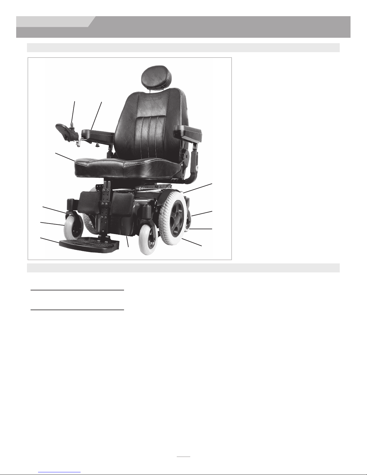
III. YOUR CHAIR AND ITS PARTS
III. YOUR CHAIR AND ITS PARTS
1. Flip-back, height adjustable armrest
2. VR2 controller joystick (RNET option)
3. Captain’s seat
4. Front Caster 7”
2
1
8
5. Rear stabilizing caster 6”
6. Single plate foot platform (shown)
Optional:
Swing-away 65° hangers
Swing-away ELR hangers
Swing-away 70° hangers
Swing-away 75° hangers (tapered)
Swing-away 90° hangers
7. Drive wheels
8. Brake release
9. Caster fork (front)
10. Caster fork (rear)
11. Front shroud
10
4
6
Weight (lbs)
Chair with Batteries
SC -260, BC -235, CC -250, MPC -350
Chair without Batteries
SC -182, BC -157, CC -172, MPC -272
Drive Wheels
13" Mag: Std. airless insert
Joystick
Option - VR2 - Right or left handed,
assembly, actuator control.
Option - RNET - (LED,Color)
Option Joystick Advanced - Color dis-
play, paddle switches, Infrared
Output, programmable buttons,
Stereo Jacks.
Batteries
(2 deep cycle batteries required to
operate chair)
Standard - Group 22
Battery Charger
Off board 8 AMP
11
7
QUICKIE PULSE
Shroud Colors
Red, Black, Blue, Silver, Copper, Green
Apple, Yellow, Pearl Pink, Candy
Purple, Matte Black, Midnight Blue,
Pearl white, Digital camo, Woodland
Camo, Carbon fiber print.
Seats, Upholstery and Style
Standard- BC & SC: A.S.A.P. II Seat Frame
CC: Captain’s Seat
Sizes: 12" - 22" wide, 12" - 22" deep
MPC: 14" - 22" wide, 16” -20” deep
Footrest:
CC: Center Mount SC & BC: Standard-
SA Swing away footrests w/heel loops
Option-Foot platform, Manual elevating legrests, Power Articulating
Legrest (ALR), Power Center Mount,
Center mount
Backrest
SC & BC: Standard Canes Angle Adjust
Option- 8° Bend, Semi Recline,
Folding
CC: standard- Captain’s Seat Back
MPC: Recline
5
Models
Pulse 6 BC, SC, and CC (shown)
Pulse 5 BC,CC
Pulse 6 MPC
Casters front
Standard- 7” solid
Casters rear
Standard- 6” solid
Armrest
SC & BC: Standard- 14" Cantilever,
height adjustable 14" arm pad
Option- Locking, two-point arm,
Dual post Arm, Single Post arm
MPC: Reclining/Otto Bock
Suspension
Standard- all wheel
All features may not be available with some chair
setups or in conjunction with another chair feature.
Please consult your supplier for more information.
Your authorized supplier can also provide you with
more information on accessories.
119832Rev. G
4
Page 5

QUI CK IE PU LS E
IV. NOTICE– READ BEFORE USE
A. CHOOSE THE RIGHT CHAIR & SAFETY
OPTIONS
Sunrise provides a choice of many power wheelchair styles, sizes
and adjustments to meet the needs of the user. However, final
selection of a wheelchair rests solely with you and your health care
professional. Choosing the best chair for you depends on such
hings as:
t
1. Your size, disability, strength, balance and coordination.
2. Your intended use, and your level of activity.
3. The types of hazards you must overcome in daily use (in
areas where you are likely to use your chair).
4. The need for options for your safety and comfort (such as
positioning belts or special seat systems).
INTENDED USE:
with wheels that is intended for medical purposes to provide
mobility to persons restricted to a sitting position.
The Quickie PULSE is a battery operated device
B. ADJUST CHAIR TO YOUR ABILITY
You need to work with your doctor, nurse or therapist, and your
supplier, to fit this chair and adjust the controller settings for your
level of function and ability.
C. REVIEW THIS MANUAL OFTEN
Before using this chair you, and each person who may assist you,
should read this entire Manual and make sure to follow all instructions. Review the warnings often, until they are second nature to
you.
D. WARNINGS
The word “WARNING” refers to a hazard or unsafe practice that
may cause severe injury or death to you or to other persons. The
“Warnings” are in four main sections, as follows:
1. V — EMI
Here you will learn about electromagnetic interference and
how it can affect your chair.
2. VI — GENERAL WARNINGS
Here you will find a safety checklist and a summary of risks
you need to be aware of before you ride this chair.
3. VII — WARNINGS — COMPONENTS & OPTIONS
Here you will learn about your chair. Consult your supplier
and your health care professional to help you choose the
best set-up and options for your safety.
4. X — BATTERIES
Here you will learn about battery and charger safety, and
how to avoid injury.
Throughout this owner’s manual and on the wheelchair you will
see the icons listed below to identify warnings and potential hazards.
WARNING!
ESD:
Electrostatic Discharge can damage printed
These warnings must be followed, failure to
do so may cause personal injury or may damage the wheelchair.
circuit boards.
WARNING
Heed all warnings to reduce the risk of unintended brake release
or chair movement:
1. Beware of the danger from hand-held transceivers. Never
turn on or use a hand-held transceiver while power to your
chair is on. Use extra care if you believe that such a device
may be in use near your chair.
2. Be aware of nearby radio or TV stations, and avoid coming
close to them.
3. If unintended movement occurs, turn your chair off as soon
as it is safe to do so.
A. WHAT IS EMI?
WARNING
1. EMI means: electromagnetic (EM) interference (I). EMI
comes from radio wave sources such as radio transmitters
and transceivers. (A “transceiver” is a device that both sends
and receives radio wave signals).
2. There are a number of sources of intense EMI in your daily
environment. Some of these are obvious and easy to avoid.
Others are not, and you may not be able to avoid them.
3. Powered wheelchairs may be susceptible to electromagnetic
interference (EMI) emitted from sources such as radio stations, TV stations, amateur radio (HAM) transmitters, two
way radios, and cellular phones.
4. EMI can also be produced by conducted sources or electrostatic discharge (ESD).
V. EMI (ELECTROMAGNETIC INTERFERENCE)
B. WHAT EFFECT CAN EMI HAVE?
WARNING
1. EMI can cause your chair, without warning, to:
• Release its brakes
• Move by itself
• Move in unintended directions
If any of these occur, it could result in severe injury to you
or others.
2. EMI can damage the control system of your chair. This could
create a safety hazard, and lead to costly repairs.
3. EMI can cause Bluetooth connection, and/or mouse interference.
C. SOURCES OF EMI
WARNING
The sources of EMI fall into four broad types:
1. Hand-Held Transceivers:
The antenna is usually mounted directly on the unit. These include:
• Citizens band (CB) radios
• “Walkie-talkies”
• Security, fire and police radios
• Mobile phones
• Lap-top computers with phone or fax
• Other personal communication devices
NOTE –
2. Wireless Routers
These devices can transmit signals while they are on, even if not
in use.
5
119832 Rev. G
Page 6

QUI CK IE PU LS E
3. Medium-Range Mobile Transceivers:
These include two-way radios used in police cars, fire trucks,
ambulances and taxi cabs. The antenna is usually mounted on the
outside of the vehicle.
4. Long-Range Transceivers:
These include commercial radio and TV broadcast antenna towers
and amateur (HAM) radios.
NOTE–
top computers (without phone or fax), Cordless phones, TV sets
or AM/FM radios, CD or tape players.
The following are not likely to cause EMI problems: Lap-
D. DISTANCE FROM THE SOURCE
WARNING
Electro-magnetic energy rapidly becomes more intense as you get
closer to the source. For this reason, EMI from hand-held devices
is of special concern.
these devices can bring high levels of EM energy very close to your
chair without you knowing it.
CAUTION -
ference or loss of connection if the wheelchair is within 1 meter
of a wireless router.
For additional detail regarding the recommended separation distance between radio frequency communication equipment and this
product, see Appendix Table 4 (Recommended separation distance
between portable and mobile RF communications equipment and
the product)
If using Bluetooth, the user might experience inter-
(See Section C.1)
A person using one of
V. EMI (ELECTROMAGNETIC INTERFERENCE)
WARNING
There is no way to know the effect on EMI if you add accessories
or modify this chair. Any change to your chair may increase the
risk of EMI. Parts not specifically tested or parts from other suppliers have unknown EMI properties. For additional detail regarding
the testing and use of this product with respect to electromagnetic
immunity, see Appendix, Tables 2 and 3 (Guidance and manufacturers declaration - electromagnetic Immunity)
F. REPORT ALL SUSPECTED EMI
INCIDENTS
WARNING
You should promptly report any unintended movement or brake
release. Be sure to indicate whether there was a radio wave
source near your chair at the time. Contact:
Sunrise Medical, Customer Service Department at (800) 333-4000.
G. EMI FROM CHAIR
WARNING
The chair itself can disturb the performance of electromagnetic
fields such as emitted by alarm systems of shops. For additional
detail regarding the testing and use of this product with respect to
electromagnetic emissions, see Appendix, Table 1 (Guidance and
manufacturers declaration - electromagnetic emissions)
H. HEAD ARRAY SAFETY AND RFI
E. IMMUNITY LEVEL
WARNING
1. The level of EM is measured in volts per meter (V/m). Every
power wheelchair can resist EMI up to a certain level. This is
called its “immunity level”.
2. The higher the immunity level, the less the risk of EMI. It is
believed that a 20 V/m immunity level will protect the
power wheelchair user from the more common sources of
radio waves.
3. The common configuration tested and found to be immune
to at least 20 V/m is: Quickie Pulse power wheelchair with a
right-hand mounted RNET remote joystick system, 18" seat
width, 18" seat depth, dual post height adjustable armrests,
fixed tapered legrests with a two piece footplate, and Gp 22
gel cell batteries.
4. All After Market input device options, classified as breath controls, Proportional controls, and/or Switched controls that
can be used with this powerchair, have an unknown effect on
their immunity level to different types of EMI. They have not
been specifically tested with the Pulse 5/6 and RNET control
system.
5. All modifications required for the common configuration to comply with ANSI/RESNA WC2/21 have been installed
WARNING
If there is any doubt that the specialty control input device is not
immune to 20V/m, extra care should be taken around known
sources of EMI.
WARNING
If you have a Head-array, the sensors used in the product have the
potential to operate unintentionally if moisture or any substance
that is electrically conductive is present in sufficient quantities.
Electro magnetic interference from electrical power lines and certain types of phones can cause the sensors to activate.
These sensors are capacitive in nature, and can generate an electronic field, which can be affected by liquids and/or a source of
radio frequency Interferance (RFI). Any material that is conductive
has the potential to activate the Head-array unintentionally.
Avoid
use under high power lines and around cell phones.
Avoid
the use of a Head Array in rain or snow and protect against
the potential of spilled liquids on the sensors.
Avoid
cell phones and electronic devices in proximity to the array.
Avoid
any source that has the potential of (RFI).
Warn
the user of this chair that the chair controls have the potential of acting erractically or making sudden stops, if (RFI) is not
avoided.
If any (RFI) causes erratic behavior, immediately cut off the power
to the wheelchair, and wait until the interference passes.
119832Rev. G
6
Page 7

QUI CK IE PU LS E
WARNING
Heed all warnings in this section. If you fail to do so, a fall, tip-over
or loss of control may occur and cause severe injury to you or
others.
A. NOTICE TO USER AND ATTENDANTS
WARNING
User:
1. Before using this chair, you should be trained in its safe use
y your health care professional.
b
2. Every wheelchair is different. Take the time to learn the feel
of this chair before you begin riding.
3. Be aware that you must develop your own methods for the
safe use of this chair that are best suited to your level of
function and ability.
4. Have someone help you practice bending, reaching and
transfers until you learn how to do them safely.
5. Never try a new maneuver on your own unless you are sure
it is safe.
6. Get to know the areas where you plan to use your chair.
Look for hazards and learn how to avoid them.
7. Always wear a positioning strap.
8. Do not use a wheelchair if the joystick does not spring back
to the neutral position.
9. Do not use your wheelchair if the joystick boot is ripped or
damaged.
10. Do not try to tip this wheelchair without an attendant present.
11. Do not allow additional riders, the chair may become unstable.
User and Attendants:
1. When transferring the user in or out of the wheelchair
never use the footplate as a platform.
2. Do not lift this wheelchair by any parts that are removable,
doing so may result in damage to the wheelchair or injury to
the user.
3. Never try to stop or slow this wheelchair with the wheel
locks (if applicable). Wheel locks are designed to prevent
the chair from moving when stopped. They are not brakes.
4. Always keep your hands and body parts clear of moving
parts to help prevent injuries.
Attendants:
WARNING
Make sure you heed all warnings and follow all instructions in each
section of this manual. Warnings that apply to the user also apply
to you.
1. Do not stand or sit on any portion of this wheelchair.
2. You need to work with the user, and the user’s doctor,
nurse or therapist, to develop safe methods best suited to
your abilities and those of the user.
3. To manually push the chair you must release the motor locks.
• Do not engage or disengage motor locks
the chair is
• Make sure you have full control over the chair when you
release the motor locks. When you do so the chair will not
have brakes.
• Make sure the chair is on level ground before you release
the motor locks.
4. Propel this chair by the push handles only. They provide
secure points for you to hold the rear of the chair to prevent a fall or tip-over.
5. Check to make sure push handle grips will not rotate or slip off.
off
.
unless
power to
VI. GENERAL WARNINGS
B. WEIGHT LIMIT
WARNING
1. The user plus items carried should never exceed the total
weight capacity identified on your chair.
2. Never use this chair for weight training.
3. Exceeding the weight limit is likely to damage the seat,
frame, or fasteners, and may cause severe injury to you or
others from chair failure.
. Exceeding the weight limit will void the warranty.
4
C. CONTROLLER SETTINGS
WARNING
Be aware that you may need to adjust the controller settings of
your chair.
1. Check and adjust the settings every six to twelve months.
2. Consult your supplier to adjust the control settings immediately if you notice any change in your ability to:
• Control the joystick
• Hold your torso erect
• Avoid running into objects.
D. SAFETY CHECK-LIST
WARNING
Before each use of this chair:
1. Make sure the chair operates smoothly. Check for noise,
vibration, or a change in ease of use. (They may indicate low
tire pressure, loose fasteners, or damage to your chair).
• Inspect any problem. Your authorized dealer can help you
find and correct the problem.
2. Make sure batteries are charged. Green lights on charge
indicator will light up when charge is full. Yellow lights indicate battery charge level is getting low. Red lights indicate
batteries are in immediate need of charging.
E. CHANGES & ADJUSTMENTS
WARNING
Never
use non-Quickie parts to replace Quickie provided parts or
make changes to your chair unless authorized by Sunrise. (Doing so
will void the warranty and may create a safety hazard.)
F. ACCESSORIES
WARNING
Accessories designed by manufacturers other than Sunrise, not available through Sunrise order process have not been tested or
approved for use by Sunrise.
1. If you modify or adjust this chair it may increase the risk of a
fall or tip-over.
2. Modifications unauthorized by Sunrise constitutes remanufacturing of the wheelchair. This voids the warranty. The
user then assumes all future liability for the wheelchair.
7
119832 Rev. G
Page 8
QUI CK IE PU LS E
VI. GENERAL WARNINGS
G. WHEN SEATED IN A PARKED
WHEELCHAIR
WARNING
Always
1.
2. Make sure that persons who help you (for example, store
turn off all power to your chair when you are
parked, even for a moment. This will prevent:
• Accidental movement from contact with the joystick by
you or others.
• Unintended brake release or movement from EMI sources.
See Section V)
(
clerks) are aware of the joystick and do not touch it. If they
do, your chair may move suddenly when you do not expect
it.
H. ENVIRONMENTAL CONDITIONS
WARNING
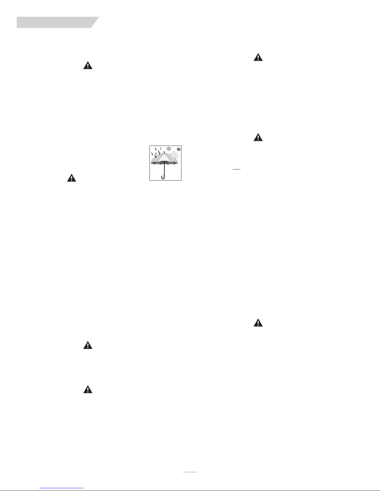
Your chair is not designed for use in a heavy rain storm, or in
snowy or icy conditions.
1. Contact with water or excessive moisture can cause an electrical malfunction. The frame, motors and other chair parts
are not water-tight and may rust or corrode from the
inside.
To avoid a chair failure:
• Minimize exposure of your chair to rain or very
wet conditions.
Never
•
• Do not use your chair in fresh or salt water (such as at the
• Make sure battery cover is secure.
• Replace joystick boot if it becomes torn or cracked.
• Make sure all electrical connections are secure.
• Dry the chair as soon as you can if it gets wet, or if you
2. Proceed slowly and use extra care if you must operate your
chair on a wet or slick surface.
• Stop if one or both main wheels lose traction. If this
•
• When in doubt, have someone help you.
3. When not in use, keep your chair in a clean, dry place.
take your chair into a shower, tub, pool or sauna.
edge of a stream, lake, or ocean).
use water to clean it.
occurs, you may lose control of your chair or fall.
Never
operate your chair on a slope or ramp if there is
snow, ice, water or oil film present.
WARNING
Extra caution should be used when employing the disc switch or
the proximity head array as control devices. These two devices
are susceptible to malfunction when wet.
I. TERRAIN
WARNING
1. This chair will perform at it’s best on firm, even surfaces
such as concrete, asphalt and indoor flooring.
2. Although equipped with suspension, the performance can be
substantially reduced on uneven surfaces and rough terrain.
3. Do not operate the chair on sand, loose gravel or soil.
Doing so may damage wheels, bearings, axles, motors or
loosen fasteners.
J. STREET USE
WARNING
1. This product is not intended for street use. Avoid streets
whenever possible.
2. Obey and follow all legal pedestrian pathways, and laws that
apply to pedestrians.
. Be alert to the danger of motor vehicles in parking lots, or if
3
you must cross a road.
4. It may be hard for drivers to see you. Make eye contact with
drivers before you proceed. When in doubt, yield until you
are sure it is safe.
K. MOTOR VEHICLE SAFETY
WARNING
Identify whether or not your chair has been manufactured with
the Transit Option installed.
If your chair is not equipped with the Transit Option: The wheelchair does not meet federal standards for seating while travelling
in a motor vehicle.
NEVER
1.
2.
3.
4.
5.
If your chair is equipped with the Transit Option:
T: “Transit Option and use”.
let anyone sit in this chair while in a moving vehicle.
ALWAYS
manufacture) motor vehicle restraints. In an accident or
sudden stop the rider may be thrown from the chair.
Wheelchair seat belts will not prevent this, and further
injury may result from the belts or straps.
NEVER
may shift and interfere with the driver.
ALWAYS
DO NOT
vehicle accident. It may have changed the structure of the
chair, and damaged, or broken components. This could lead
to a risk of injury or damage to your chair. If the wheelchair
has been involved in an accident, discontinue use and contact your supplier for a thorough inspection.
secure the rider with OEM (original equipment
transport this chair in the front seat of a vehicle. It
secure this chair so that it cannot roll or shift.
use any chair that has been involved in a motor
See section VII-
L. CENTER OF BALANCE
WARNING
The point where this chair will tip forward, back, or to the side
depends on its center of balance and stability.
The Center Of Balance Is Affected By:
1. The seat height and seat angle.
2. A change in your body position, posture or weight distribution.
3. Using this chair on a ramp or slope.
4. The use of a back pack or other options, and the amount of
added weight.
5. Center or rear Drive wheel positioning.
To Reduce The Risk Of A Fall Or Tip-Over:
1. Whenever a condition exists that may change the center of
balance, reduce speed, proceed cautiously.
2. When in doubt, always have someone help you.
119832Rev. G
8
Page 9

QUI CK IE PU LS E
VI. GENERAL WARNINGS
M. TRANSFERS
WARNING
It is dangerous to transfer on your own. It requires good balance
and agility. Be aware that there is a point during every transfer
when the wheelchair seat is not below you. To prevent a fall:
Always
1.
2. Make sure motor brakes are engaged. This keeps the chair
3. Work with your health care professional to learn all safe
4. Move your chair as close as you can to the seat you are
5. Rotate the front casters until they are as far forward as possible.
6. Be careful of the footrests. If you can, remove or swing
7. Make sure armrests do not interfere.
8. Transfer as far back onto the seat surface as you can. This
turn off power before you transfer to or from your
chair. If you fail to do so you may touch the joystick and
cause your chair to move when you do not expect it.
from moving when you transfer.
methods for transfers.
Learn how to position your body and how to support
•
yourself during a transfer.
• Have someone help you until you are sure you can do a
safe transfer on your own.
transferring to. If possible, use a transfer board.
them out of the way.
• As a standard rule, never stand on footrests when you
transfer. Doing so may damage them or cause your chair
to tip. If the footplate is in contact with the ground, it is
possible to use the footplate for a transfer.
• Make sure your feet do not “hang up” or get caught in the
space between the footrests.
will reduce the risk that you will miss the seat or fall.
N. REACHING OR LEANING
WARNING
Reaching or leaning affects the center of balance of your chair. If
done improperly, a fall or tip-over is likely. When in doubt, ask for
help or use a device to extend your reach.
To Reduce the Risk of injury and/or Damage to the Chair:
Never
1.
2.
3.
4.
5.
6.
IF YOU MUST REACH OR LEAN, DO SO AT YOUR OWN RISK.
Remember to:
1. Move your chair as close as you can to the object you wish
2. Rotate the front casters until they are as far forward as pos-
NOTE
3. Turn off all power to your chair. If you fail to do so, you
reach or lean if you must shift your weight sideways or
rise up off the seat.
Never
reach or lean if you must move forward in your seat
to do so. Always keep your buttocks in contact with the
backrest.
Never
reach with both hands (you may not be able to catch
yourself to prevent a fall if you lose your balance).
Never
try to pick up an object from the floor by reaching down
between your knees.
Never
put pressure on the footrests while reaching.
Never
reach or lean over the top of the seat back. This may
damage the backrest and cause you to fall.
to reach.
sible. This makes the chair more stable.
–To do this: Move your chair past the object you want to reach,
then back up alongside it. Backing up will rotate the casters forward.
may touch the joystick and cause your chair to move when
you do not expect it.
O. DRESSING OR CHANGING CLOTHES
WARNING
Be aware that your weight will shift if you dress or change clothes
while seated in this chair. To make the chair more stable, rotate
the front casters until they are in the
forward position
.
P. OBSTACLES
WARNING
Riding over curbs or obstacles can cause tipping and serious bodily
harm. If you have any doubt that you can safely cross any curb or
obstacle, ALWAYS ASK FOR HELP. Be aware of your riding skills
and personal limitations. Develop new skills only with the help of
a companion.
1. Be aware that thresholds are very dangerous. (Even a small
change in height may stop a caster wheel and cause your
chair to tip). You may need to:
• Remove or cover threshold strips between rooms.
• Install a ramp at entry or exit doors.
2. Keep your eyes moving when you ride; scan the area well
ahead of your chair.
3. Make sure the floor areas where you use this chair are level
and free of obstacles.
Q. DRIVING IN REVERSE
WARNING
Use extra care when you drive your chair in reverse. You may
lose control or fall if one of the rear wheels hits an object.
1. Operate your chair slowly and at an even speed.
2. Stop often and check to make sure your path is clear of
obstacles.
R. RAMPS, SLOPES & SIDEHILLS
WARNING
Your center of balance changes when you are on a slope.
NOTE –
Beware Of:
“Slope” includes a ramp or sidehill. Your chair is less sta-
ble when it is at an angle. Never use this chair on a
slope unless your are sure it is safe. When in doubt,
have someone help you.
1. Steep slopes. Do Not use this chair on a slope steeper than
6%. (A 6% slope means: One foot in elevation for every ten
feet of slope length).
2. Wet or slippery surfaces (such as when ice, snow, water or
oil film is present). A loss of traction may cause a fall or tipover.
3. A change in grade on a slope (or a lip, bump or depression).
These may cause a fall or tip-over.
4. A drop-off at the bottom of a slope. (A drop-off of as small
as 3/4 inch (19 mm) can stop a front caster and cause the
chair to tip forward).
9
119832 Rev. G
Page 10

QUI CK IE PU LS E
S. REDUCE THE RISK OF A FALL, TIP-OVER OR
LOSS OF CONTROL
WARNING
Never
1.
2.
.
3
4. Keep your chair moving at a slow, steady speed. Keep con-
use your chair on a slope unless you are sure you can
do so without losing traction.
Always
go as straight up and as straight down as you can.
Do not
•
•
Always
be wide enough so that the wheel won’t roll off of the side
of the ramp.
trol over the chair at all times.
• On a descent, do not let your chair accelerate beyond its
• If the chair picks up speed, center the joystick to slow
• If you stop, re-start slowly
“cut the corner” on a slope or ramp.
Do not
turn or change direction on a slope.
tay in the center of the ramp. The ramp needs to
s
normal speed.
down or stop.
T. RAMPS AT HOME & WORK
WARNING
Before driving on a ramp, survey the condition of the ramp. On
slippery ramps traction may be reduced causing your wheelchair
to slide.
VI. GENERAL WARNINGS
Avoid
4.
moving forward if a wheel is “hung up” on the lip of
the ramp. Backup, reposition the caster for a more direct
approach. And slowly try again.
V. CURBS & SINGLE STEPS
WARNING
1. Sunrise recommends that you avoid climbing and/or descending
a curb, single step, or other obstacle, and that a ramp or curb
cutout is always used.
2. If you must climb or descend a curb, single step, or other
obstacle that is greater than 2.5", it is recommended to have
person assist you in doing so.
a
DO NOT
3.
greater than 4" high.
4. If you must climb or descend a curb or step alone do so at your
own risk using extreme care and use the following procedure:
• Proceed slowly, at a steady speed
• Go as straight up or down as you can over the obstacle.
Never turn when trying to climb or descend an obstacle,
doing so may result in a fall or tip-over.
5. Failure to follow the above recommendations may cause:
• A Fall or Tip Over
• Damage to the frame, wheels, axles or other parts, or
loose fasteners.
try to climb a curb, single step, or other obstacle
W. STAIRS
WARNING
NOTE–
Make sure ramps meet all Building Codes for your area.
1. For your safety, have a licensed contractor build or remodel
the ramp to meet all local codes and standards.
2. The proper design will vary, depending on such things as: the
length and height of the ramp; the need for an intermediate
platform; landing size; doors, and the direction of swing, and;
whether the ramp includes a turn or angle.
At A Minimum:
1. Open sides of ramp must have side rails to prevent your
chair from going over the edge.
2. Slope must not be steeper than one inch in height for every
one foot of slope length (approximately 10º).
3. Ramp surface must be even, and have a non-skid surface.
4. You may need to add a section at the top or bottom to
avoid a lip or drop-off.
5. Ramp must be sturdy. Add bracing if needed, so ramp does
not “bow” when you ride on it.
U. WHEELCHAIR LIFTS
WARNING
Wheelchair lifts are used in vans, buses, and buildings to help you
move from one level to another.
Always
1.
lift. If you fail to do so, you may touch the joystick by accident and cause your chair to drive off the platform. (Be
aware that a “roll-stop” at the end of the platform may not
prevent this).
2. Make sure there is not a lip or drop-off at the top or bottom of the platform. These may cause a fall or tip-over.
When in doubt, have someone help you.
Always
3.
falls while on a lift.
off
turn
position the user securely in the chair to help prevent
all power to your chair when you are on a
WARNING
Never use this chair to go up or down stairs, even with an attendant. Doing so is likely to cause a fall or tip-over.
X. ESCALATORS
WARNING
Never take this chair on an escalator, even with an attendant.
Doing so is likely to cause a fall or tip-over.
119832Rev. G
10
Page 11

QUI CK IE PU LS E
WARNING
Note: If you use parts or make changes not authorized by Sunrise
t may create a safety hazard and will void the Warranty.
i
A. ARMRESTS
WARNING
1. Armrests will not bear the weight of this chair.
Never
2.
lift this chair by its armrests. They may come loose
or break.
VII. WARNINGS: COMPONENTS AND OPTIONS
F. MOTOR LOCKS
WARNING
1. Do not engage or disengage motor locks
2. Be aware that the chair
. Make sure that the person pushing the chair has full control
3
4. Make sure that the chair is on level ground when motor
off
chair is
locks are in the free-wheel position.
when motor locks are disengaged.
locks are disengaged.
.
will not have brakes
unless
when motor
power to the
B. BATTERIES
WARNING
Always
1.
2.
3. Only
4. Read all of section
wear rubber gloves and safety glasses when you han-
dle batteries.
Never
smoke or hold an open flame near batteries. They
are a known explosion hazard.
deep cycle sealed case
used in this device.
X. Batteries
or charge batteries.
construction batteries should be
before attempting to change,
C. CUSHIONS & SLING SEATS
WARNING
1. Standard foam cushions and other body supports are not
designed for the relief of pressure. Do not sit directly on a
sling surface.
2. If you suffer from pressure sores, or if you are at risk that
they will occur, you may need a special seat system or a
device to control your posture.
• Consult your healthcare professional to find out if you
need such a device for your well-being.
D. FASTENERS
WARNING
Many of the screws, bolts and nuts on this chair are special highstrength fasteners. Use of improper fasteners may cause your
chair to fail.
1. Only use fasteners provided by Sunrise.
2. If fasteners become loose, tighten them immediately.
3. Over- or under-tightened fasteners can cause damage to
your chair or it’s components.
E. FOOTPLATE & FOOTRESTS
WARNING
1. At the lowest point, footrests should be
(65 mm) off the ground. If set too LOW, they may “hang
up” on obstacles you can expect to find in normal use. This
may cause the chair to stop suddenly and tip forward.
2. To avoid a trip or fall when you transfer:
• Make sure your feet do not “hang up” or get caught in the
space between the footrests.
• Avoid putting weight on the footrests, as the chair may tip
forward.
• Remove or swing the footrests out of the way, if possible.
3. The footrest should always be in the down position when
operating the chair.
4. Never lift this chair by the footrests. Footrests detach and
will not bear the weight of this chair. Lift this chair only by
non-detachable parts of the main frame.
at least 2 1/2 inches
G. ON/OFF SWITCH
WARNING
Never
1.
2. To slow your chair to a stop, return the joystick to neutral.
use the ON/OFF switch to stop the chair
an emergency. This will result in an
cause you to fall.
abrupt
except
stop, and may
in
H. PNEUMATIC TIRES
WARNING
Proper inflation extends the life of your tires and makes your chair
easier to use.
1. Do not use this chair if any of the tires are under- or overinflated. Check weekly for proper inflation level, as listed on
the tire sidewall.
2. Low pressure in a tire may cause the chair to veer to one
side and result in a loss of control.
3. An over-inflated tire may burst.
Never
4.
5. Driving over sharp objects may cause damage to pneumatic
use a gas station air pump to inflate a tire. Such
pumps provide air at
to burst. To prevent tire damage:
• Use a hand pump (or
• Use a tire gauge to check pressure.
tires and tubes.
high volume
low volume
, and could cause the tire
air pump) to inflate tires.
I. POSITIONING BELTS (Optional)
WARNING
The positioning belt is predominately used to support your posture. It can also be used to limit slipping and/or sliding that you
might experience when the chair is in motion. The positioning
belt is not a transit rated safety belt and should not be used in the
place of a seat belt while being transported in a motor vehicle.
Improper use of Positioning belts may cause severe injury or
death. If you use a positioning belt, be sure to follow the recommendations in this section:
1. Make sure the rider does not slide down in the wheelchair
seat. If this occurs, the rider may suffer chest compression
or suffocate due to pressure from the belts.
2. The belts must be snug, but must not be so tight that they
interfere with breathing. You should be able to slide your
open hand, flat, between the belt and the rider.
3. A pelvic wedge or a similar device can help keep the rider
from sliding down in the seat. Consult with the rider’s doctor,
nurse or therapist to find out if the rider needs such a device.
4. Use positioning belts only with a rider who can cooperate.
Make sure the rider can easily remove the belts in an emergency.
11
119832 Rev. G
Page 12

QUI CK IE PU LS E
VII. WARNINGS: COMPONENTS AND OPTIONS
5. NEVER use positioning belts
a. As a patient restraint. A restraint requires a doctor’s
order.
b. On a rider who is comatose or agitated.
c. As a motor vehicle restraint. In an accident or sudden
stop the rider may be thrown from the chair.
Wheelchair seat belts will not prevent this, and further
f you fail to heed these warnings, damage to your chair, a fall, tip-
I
over or loss of control may occur and cause severe injury to the
rider or others.
injury may result from the belts or straps.
J. PUSH HANDLES
WARNING
1. Push handles provide secure points for an attendant to propel
and control the chair. This helps to prevent a fall or tip-over.
2. Check to make sure push handle grips will not rotate or slip off.
K. SEATING SYSTEMS
WARNING
1. Use of a seating system not approved by Sunrise may alter the
center of balance of this chair. This may cause a fall or tip-over.
Never
2.
3. Never raise your seating system to a height of more than
change the seating system of your chair unless you
consult your supplier first.
22" (measuring from the front of the seat pan to the floor)
with all actuators in their home position.
L. UPHOLSTERY FABRIC
WARNING
1. Replace worn or torn fabric of the seat sling and seat back
as soon as you can. If you fail to do so, the seat may fail and
cause you to fall. Worn fabrics may increase the potential
for a fire hazard.
2. Sling fabric will deteriorate with age and use. Look for fraying, thin spots, or stretching of fabric at rivet holes. Replace
fabric as required.
3. Be aware that washing may reduce flame retardation qualities of the fabric.
M. SUSPENSION
WARNING
No component of the chair, was made with natural rubber latex,
Including the Suspension system.
P. POWER SEATING (SC,MPC)
WARNING
1. Operation
• While driving this wheelchair in the reclined, elevated, or
tilted position use caution.
Do Not attempt to operate any power seating option
•
while positioned on an incline.
• Do Not attempt to operate any power seating option
while this wheelchair is in motion.
• Do not attempt to operate the lift or tilt power seating
options around children.
• Through programming it is possible to reverse the direction
of all powered seating functions, ensure you know which
direction your seat is going to move before operating.
2. Reduced Speed Driving (Creep)
This power chair is designed to automatically reduce the maximum
driving speed to a creep mode when certain power seating limits
are reached.
3. Pinch points
Pinch points may occur when operating the powered seating
options on this chair. Ensure all hands and body parts are clear of
all power seating components that may result in pinch points
before operating them.
4. Tilting Power Base with Push Handles
Do not attempt to tilt power wheelchairs by pulling down on the
push handles. Power wheelchairs have heavy bases. As such, attempting to tilt a power wheelchair to traverse obstacles can damage components in the seating system and/or modular actuators.
5. Remain Clear During Power Accessory Operation
Please stay clear of any powered actuator while the component is
in motion. Sunrise power mechanisms move over large ranges of
travel. Users should be aware of their surroundings while components are in motion.
6. Maximum User Weight
Do not exceed the weight capacity for your specific chair/seating system configuration. Doing so could result in premature failure or injury.
7. Latch Mode
While operating any power seating function in latched mode use
caution. In latch mode, powered seating will not stop until a
reverse command is performed or the end of travel is met.
N. WIRING
WARNING
Never pull on cables directly. This can result in wires breaking
inside the connector or harness. To remove a plug or connector,
always grasp the plug or connector itself.
O. ASSIGNABLE CONTROLS
WARNING
It is possible to assign a function to buttons, or jacks of your wheelchair . If controls have been assigned to perform a dual or alternate
function ensure you know what each control operates. Please contact your Authorize Dealer or the Quickie Technical Service
Department if you do not receive this information.
119832Rev. G
Q. S.P.O.T.
POWER ACCESSORY (
(Single Power Option Tilt)
SC only
)
WARNING
The powered S.P.O.T. accessory for this chair has a maximum
user weight capacity of up to 300 lbs. Never exceed this capacity
while operating the powered actuator.
WARNING
The powered S.P.O.T. should not be operated for more than
three minutes of continuous use. Doing so may shorten the life of
the powered S.P.O.T.
12
Page 13

QUI CK IE PU LS E
R. POWER RECLINE
WARNING
Pinch Point
Avoid putting hands or fingers near the power recline mechanism
while in operation.
Weight Capacity
The maximum user weight capacity for the power recline is 250lbs
if the seat depth is less than 17 inches, and up to 300 lbs for any
seat depth over 17 inches. Exceeding this weight capacity could
lead to injury and/or permanent damage to the equipment.
VII. WARNINGS: COMPONENTS AND OPTIONS
WARNING
Wheelchairs with adjustable seat angles must be set to 10°. Do
not alter or substitute wheelchair frame parts, components, or
seating systems.
A sudden stop and/or collision may structurally damage your
wheelchair. Wheelchairs involved in such incidents should be
replaced.
Spill proof batteries, such as “gel cells”, should be installed on
wheelchairs that will experience travel in a motor vehicle.
S. POWER LEGREST ACCESSORY
The power legrest accessory has a maximum user weight
capacity of up to 300 lbs depending on your chair configuration.
Never exceed this capacity while operating the powered actuator.
T. TRANSIT OPTION AND USE
Refer also to sections VI-K: “Motor Vehicle Safety” for additional
transit option and motor vehicle warnings.
WARNING
Contact Sunrise Medical customer service (800-333-4000) with
any questions about using this power wheelchair for seating in a
motor vehicle, or if your chair is a candidate for the transit option.
Whenever possible, wheelchair occupants should transfer into the
vehicle seat and use the OEM (Original Equipment Manufacturer)
vehicle-installed restraint system.
This wheelchair has been dynamically tested in a forward-facing
mode with a specified crash test dummy restrained by both pelvic
and upper-torso belt(s) (shoulder belts). It has been determined
that both the pelvic and upper-torso belt(s) should be used to
reduce the possibility of head and chest impacts with vehicle components. When travelling in a motor vehicle, use only Wheelchair
Tie-down and Occupant Restraint Systems (WTORS) which meet
the requirements of the SAE (Society of Automotive Engineers)
J2249 Recommended Practice.
WARNING
This wheelchair has been tested for seating in a motor vehicle with
the factory-installed seating system only. This wheelchair must be
in a forward facing position during travel in a motor vehicle.
This wheelchair is equipped with wheelchair-anchored pelvic belts.
It has been dynamically tested to rely on wheelchair-anchored
pelvic belts. If desired, vehicle-anchored pelvic belts may also be
used. It is strongly recommended that the combination of both
pelvic and upper-torso belt(s) be used to reduce the risk of injury
if a sudden stop and/or collision were to occur.
WARNING
NOTE–
Pulse for the purposes described in this manual.
ABOUT TRANSPORT READY PACKAGES
The Quickie Pulse Transit System includes four factory-installed
transport brackets and an optional wheelchair anchored pelvic
belt. The Quickie Pulse 6 has been crash-tested in accordance
with ANSI-Resna WC Vol 1 Section 19 Frontal Impact Test
requirements for wheelchairs with a 170 lb crash dummy. As of
this date, the Department of Transportation has not approved any
tie-down systems for transportation of a user while in a wheelchair, in a moving vehicle of any type. It is Sunrise Medical’s position that users of wheelchairs should be transferred into the vehicle seating when transport is necessary and that the restraints
made available by the auto industry be used.
tion systems
COMPLIANCE INFORMATION
This wheelchair conforms to the requirements of the ANSI-Resna
WC Vol 1 Section 19.
NOTE–
Only use the transit brackets included with the Quickie
Sunrise Medical does not recommend any wheelchair transporta-
ANSI stands for: American National Standards Institute.
Resna: Rehabilitation Engineering and Assistive Technology
Society of North America.
WARNING
This wheelchair has been dynamically tested in a forward-facing
mode with a specified crash test dummy, restrained by both pelvic
and upper-torso belts in accordance with ANSI-Resna WC Vol 1
Section 19. Both pelvic and upper-torso belts should be used to
reduce the possibility of head and chest impacts with vehicle components in the event of a sudden stop and/or collision.
WARNING
To reduce the potential of injury to vehicle occupants, wheelchairmounted accessories, including but not limited to IV poles, trays,
respiratory equipment, backpacks, and other personal items should
be removed from the wheelchair and secured separately. Postural
supports, positioning devices, and/or strap(s) should not be relied
on for occupant restraint. These items may be used in addition to
the wheelchair anchored, or vehicle-anchored belts.
13
119832 Rev. G
Page 14

QUI CK IE PU LS E
VII. WARNINGS: COMPONENTS AND OPTIONS
1
SECURING THE WHEELCHAIR TO THE VEHICLE
2
WARNING
This wheelchair must be in a forward facing position during travel in a motor vehicle.
The recommended clear zones for wheelchair seated occupants restrained by both
elvic and upper-torso belt(s) and only by a pelvic belt are shown in the diagrams
p
and described below. Frontal Clear Zones (FCZ) need to be larger when upper
torso belt(s) are not used. The Rear Clear Zone of 16in is measured from the rearmost point on an occupant’s head. The Frontal Clear zone is measured from the
front most point of an occupant’s head and is 26-inches with pelvic and upper-torso
belt(s) and 37 inches with only a pelvic belt. The frontal clear zone may not be
achievable for wheelchair- seated drivers.
The estimated seated height (HHT) from the ground or floor to the top of the
wheelchair-seated occupant’s head ranges from approximately 47 inches for a small
adult female to about 61inches for a tall adult male.
SECUREMENT POINTS
Rear securement points(A), front securement points(B), Pelvic Belt Securement
point(C), Attach WTORS to the tie-down brackets in accordance with the manufacturer’s instructions and SAE j2249.
SECURING THE WHEELCHAIR
This wheelchair is to be used only with Wheelchair Tie-down and Occupant
Restraint Systems (WTORS) that have been installed in accordance with the manufacturer’s instructions and SAE J2249.
NOTE–
A copy of SAE J2249 Wheelchair Tie-down and Occupant Restraint Systems
(WTORS) for use in Motor Vehicles can be obtained from:
SAE International
400 Commonwealth Drive.
Warrendale, PA. 15096-0001
(877) 606-7232 or (724) 776-4970
1
2
HHT
SECURING THE OCCUPANT:
3
WHEELCHAIR-ANCHORED BELTS
4
WARNING
Only use a pelvic belt system that meets the requirements of ANSI-Resna WC Vol 1
Section 19 and SAE J2249, and has been specified to work in conjunction with the
Quickie Pulse 6 transit system.
1. Installation
a. Install the pelvic belt (D) onto the pelvic belt securement point anchored to
the seating frame of the Quickie Pulse 5 or 6. Using a 10mm Hex key, torque
the screw to 144in-lbs securing the pelvic belt to the mounting anchor (C).
b. Repeat step 1 for the opposite side.
c. Upper torso attachment point(E) shown.
3
B
A
C
4
D
E
C
119832Rev. G
14
Page 15

QUI CK IE PU LS E
VII. WARNINGS: COMPONENTS AND OPTIONS
4
VEHICLE-ANCHORED BELTS
This wheelchair has an overall rating of “A” with regard to accommodating the use
and fit of vehicle-anchored belts.
his rating is scored as follows: A = Excellent, B = Good, C = Fair, D= poor.
T
The test for Lateral Stability Displacement for Point (P) is shown in the figure at
right. The average test result for point (P) is:
• Quickie Pulse 6 - 0.547inches (13.9mm)
Quickie Pulse 5 - 0.547inches (13.9mm)
•
NOTE–
Figure 5 shows the rear view of the wheelchair and human surrogate secured
on test platform and tilted to 45°.
5
SEATING SYSTEM
WARNING
This wheelchair has been tested for seating in a motor vehicle with the factory
installed seating system only. Ensure that the factory installed seating system is
secured to the
wheelchair frame before operation. Refer to the seating system owner’s manual for
further information.
CAPTAIN’S SEAT OPTION
6
LOCKING PIN ACTIVATION
7
WARNING
5
6
A
Captains seat must be used in conjunction with WC-19 Tie-down brackets
1. Configuration for standard use (Driving the Chair)
• Locking Pin Lever (A) should be disengaged. (Figure 6)
• Backrest can be reclined or folded as needed.
2. Transit Configuration (Captains seat used in a vehicle)
• Locking Pin Lever (B) should be engaged. (Figure 7)
• Backrest is now in locked position (99°)
MAKE SURE TO ENGAGE LOCKING PIN FOR TRANSIT USE.
7
B
15
119832 Rev. G
Page 16
QUI CK IE PU LS E
VII. WARNINGS: COMPONENTS AND OPTIONS
POSITIONING BELTS
9 108
WARNING
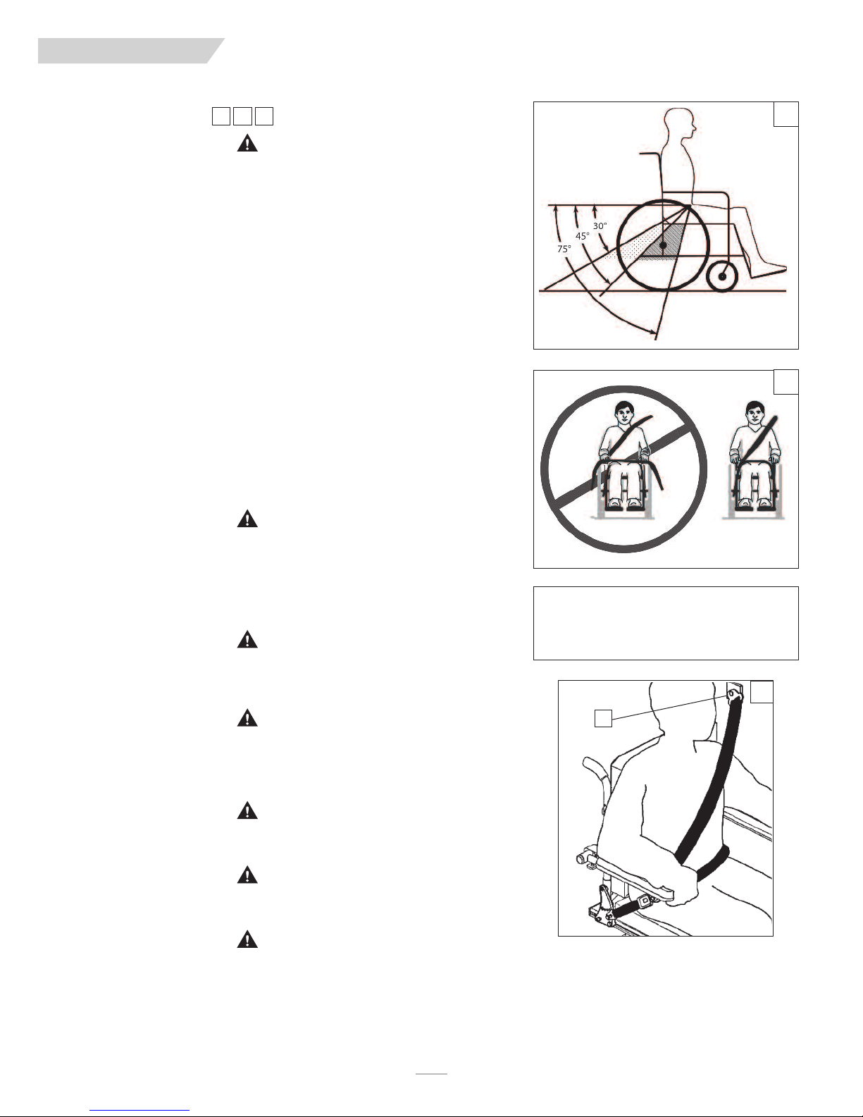
The angle of the pelvic belt should be within the preferred zone of 45 to 75 degrees
to the horizontal or within the optional zone of 30 to 45 degrees to the horizontal.
Steeper side-view pelvic belt angles are especially important if the pelvic belt is
intended to be used for postural support in addition to occupant restraint in a
frontal crash. Steeper angles will reduce the tendency for a vertical gap to develop
between the user and the belt due to compliance of seat cushions and belt movement, thereby reducing the tendency for the user to slip under the belt and for the
belt to ride up on the soft abdomen during normal use. Steeper belt angles also
educe the tendency for upper-torso belts to pull the pelvic belt onto the abdomen
r
during frontal impact loading.
1. Proper Installation
a. The pelvic belt should be worn low across the front of the pelvis.
b. Position the upper torso belts over the shoulders.
c. The belt(s) should not be held away from the body by the wheelchair compo-
nents or parts, including
but not limited to the armrests or wheels.
d. Ensure the belt(s) are not twisted.
e. Adjust belts as firmly as possible being mindful of user comfort
f. Place the upper-torso belt across the middle of the shoulder and the center of
the chest, and connect to the pelvic belt near the hip of the power chair occu-
pant.
GENERAL USE WARNINGS
8
9
WARNING
If the total weight of the power chair exceeds 275lbs(125Kg), it is recommended that
two additional ANSI/RESNA WC/Vol.4, Section 18/ISO 10542 compliant rear securement straps be used to anchor the power chair during motor vehicle transport. For
power chairs that exceed the weight threshold mentioned above, It is further recommended that the vehicle used for transport have a gross vehicle weight greater
than 8800lbs(4000Kg) if the option exists.
WARNING
The buckle of the belt restraint system should not be located near any item that may
come in contact with the buckle release button in the event of a vehicle accident or
collision.
WARNING
If a recline angle is required during transport, the Power chair seat/back should be
positioned at an angle of no more than 30° to the vertical or the occupant is at risk
of injury from sliding under the restraint in the event of an accident or collision while
in the motor vehicle.
WARNING
Visually inspect all WTORS equipment at least once per month, and have worn or
broken components replaced immediately.
WARNING
Interior components that can’t be removed from the clear zones should be padded
with material that complies with FMVSS201.
If an Upper torso belt is in use, the anchor
point(A) should be above and behind the
occupant to ensure the occupant is properly
restrained during transport.
10
A
WARNING
Although postural supports and belts may be used in a moving vehicle in addition to
the occupant belt restraint system, they should not be relied upon to replace occupant restraints that have been designed and tested for the purpose of securing an
occupant during a motor vehicle collision or accident. Any postural supports that
can be used during transit, must be positioned so that they do not interfere with the
clear path for proper transit securement belt restraint.
119832Rev. G
16
Page 17
QUI CK IE PU LS E
VIII. USE AND MAINTENANCE
WARNING
The owner and/or Caregiver for the use of this product, is responsible for
making sure that it has been setup and adjusted by a trained service professional under the advice of a healthcare advisor. The chair may require
periodic maintenance or certain in-use adjustments that may be performed
by the owner or caregiver.
A. INTRODUCTION
WARNING
. Your chair needs regular maintenance for peak performance
1
and to avoid injury from chair failure, damage or premature
wear.
2. Inspect and maintain this chair per the “Safety Checklist”.
3. If you detect a problem, make sure to service or repair the
chair before use.
4. At least once a year, have a complete safety check and service
of your chair performed by a supplier.
B. CLEANING
1. Paint Finish:
• Clean the paint finish with mild soapy water monthly.
• Protect the paint with a coat of non-abrasive auto wax every
three months.
2. Motors:
• Clean around motor area weekly with a slightly damp (not
wet) cloth.
• Wipe off or blow away any fluff, dust, or dirt on or around
the motors.
NOTE
– You do not need to grease or oil the chair.
3. Upholstery:
• Hand-wash only as needed. Machine washing may damage
fabric.
• Drip-dry only. Heat from a dryer may damage fabric.
NOTE–
Washing the fabric may decrease fire retardant properties.
4. Joystick:
• Use a cloth that has been slightly dampened with diluted
detergent. to clean the joystick and boot.
• LCD Screen can be cleaned with a soft, lint free, dry cloth.
NOTE –
NEVER use any type of window cleaner, scouring powder, or any
cleanser with solvents such as alcohol, benzene, ammonia, or
paint thinner. Never use abrasive pads or paper towels.
1. Airing up your tire:
CAUTION–
a.
• Use a hand pump (or a low volume air pump)
to inflate tires. Use a tire gauge to check pressure.
. Remove the air stem cap.
b
c. Inflate the tire to the proper pressure level (listed on the
tire sidewall)
To prevent tire damage:
E. MOTOR BRUSHES
Check the motor brushes every four (4) months for wear. The
brushes should be clean and shiny. Replace worn or blackened
brushes
F. DISPOSING OF BATTERIES
WARNING
1. All batteries, once they have reached the end of their useful
life are deemed to be hazardous waste.
2. For further information on handling and recycling contact
your local recycling authority.
3. Always dispose of product through a recognized agent.
G. ORDERING PARTS
When you order parts, provide the following:
1. Model of chair
2. Serial number of chair
3. Left hand or right hand control
4. Part number, description and quantity of parts you need.
5. State reason for replacement.
H. SAFETY CHECKLIST
You should check the items on this chart at the indicated intervals.
If any of the items are loose, worn, bent or distorted, immediately
have them checked and/or repaired by your Authorized Dealer.
Frequent maintenance and servicing will improve performance,
extend wheelchair life, and help prevent injuries.
C. STORAGE TIPS
1. Store your chair in a clean, dry area. If you fail to do so, parts
may rust or corrode.
2. Before using your chair, make sure it is in proper working
order. Inspect and service all items on the “Safety Checklist”.
3. If you store this chair for more than three months, have it
inspected by a supplier before use.
4. Use petroleum jelly to re-grease the terminals after connecting cable to battery. (Completely cover the terminal nut and
bolt, cable clip and any exposed cable with jelly).
D. TIRE PRESSURE
WARNING
1. Check for signs of wear and correct air pressure in pneumatic tires weekly.
2. For best performance, inflate tires to the same pressure
level, as shown on the tire sidewall:
• 14" pneumatic drive wheels– 35 to 45 psi (240 to 310 Kpa)
Daily
Weekly
SAFETY & FUNCTION CHECK
Charge Batteries R
Check tires for proper inflation level R
Check plugs and connectors for
proper connections R
Check all moving parts for wear R
Inspect all nuts, bolts and fasteners
for looseness or wear R
Inspect upholstery for wear R
Service by Authorized Supplier R
17
Monthly
Quarterly
Annually
119832 Rev. G
Page 18
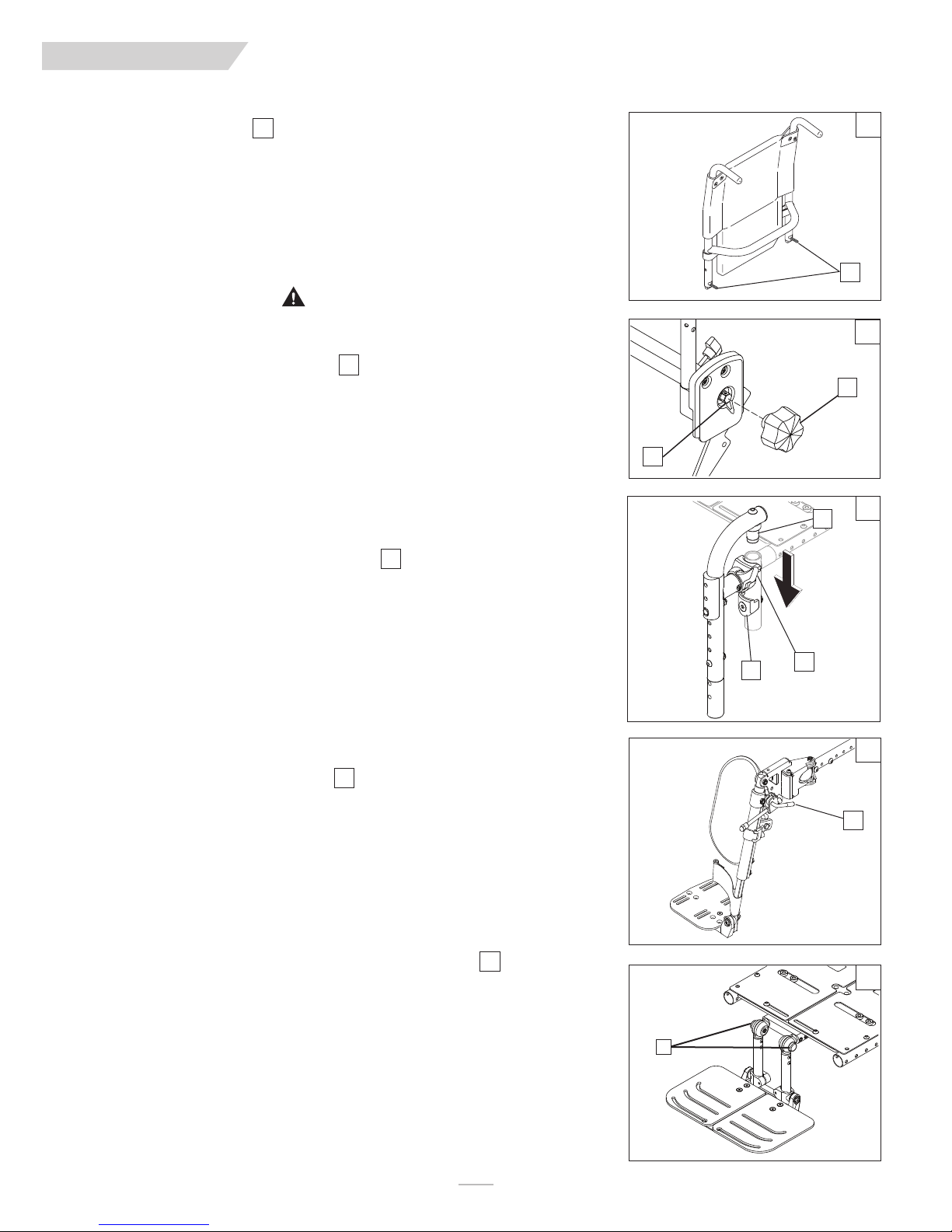
QUI CK IE PU LS E
VIII. USE AND MAINTENANCE
I. FOLDING BACKREST
Pulse wheelchairs are shipped with backrest in folded position. (optional)
1. Upright Positioning
a. Lift backrest to upright position so that latch handles (A) lock into place.
. Backrest is ready for use.
b
2. Folding Backrest
a. Lift and turn backrest latch handles (A) inward or outward.
b. Fold backrest forward.
11
WARNING
Backrest latches must be locked into place before operating wheelchair.
J. MANUAL RECLINE OPERATION
The ASAP II seating system has two manual recline options.
1. Manual operation with wrench
a. Using a 16mm socket wrench at point (A) Rotate clockwise to recline, and counter-
clockwise to return the back to an upright position.
b. Backrest is ready for use.
2. Manual operation with recline knob
a. Using the manual recline knob (B) on the side of the chair, rotate clockwise to
recline, and counter-clockwise to return the back to an upright position
K.SWING-IN / SWING-OUT FOOTRESTS
12
13
11
A
1
2
B
A
13
D
Swing-in-Swing-out Hangers and Footrests are available in (80° & 90º)
1.
Installation
a. From the side, place the pivot (D) into the top of the frame tube which guides the
hanger into the correct alignment with the locking plate (C) on front frame tube.
b. Rotate the hanger to the front until it locks into place on locking plate.
2.
Removal
a. To remove footrest, release latch (B) by pulling lever upward or pushing lever down-
ward.
b. Rotate footrest inward or outward and lift it out of the front frame tube.
L. ELEVATING LEGREST
1. Installation
To install or remove Elevating Legrest (ELR) see instructions for Swing-away Footrest installation.
2. Adjustment
a. To raise legrest, lift to desired position. Legrest will automatically lock in place.
b. To lower legrest, while seated in chair, first lift slightly then press release lever (E)
down and lower legrest to desired position.
(Optional)
M. ANGLE ADJUSTABLE CENTER MOUNT FOOTREST
1. Quick Independent angle adjustment
a. Depress the button(F) and angle adjust the footplates as an assembly or independantly
of each other.
2. Adjustment
a. To raise legrest, lift to desired position. Legrest will automatically lock in place.
b. To lower legrest, while seated in chair, first lift slightly then press the button (F) and
lower legrest to desired position.
14
15
C
B
14
E
15
F
119832Rev. G
18
Page 19

QUI CK IE PU LS E
VIII. USE AND MAINTENANCE
N. DUAL-POST FIXED HEIGHT STANDARD AND DUAL-POST HEIGHT
ADJUSTABLE ARMRESTS
The dual-post flip-back armrest can be either a flip-back or removable armrest.
1. Installing Armrest
. Insert front and rear posts into armrest receivers.
a
b. Engage levers (A and B) to secure armrest.
2. Flip-back Operation
a. Disengage lever (A) so front post is able to come free.
b. Armrest now has the ability to be flipped back without removal.
3. Removal
a. Disengage levers (A and B) so front and rear posts are able to come free.
b. Armrest can now be easily removed for transferring.
4. Height-Adjustment (option)
a. Release the upper securing lever (C).
b. Set at desired height
c. Return securing lever to locked position.
d. Move armrest up or down to allow armrest to snap into place
(Optional)
O. SINGLE POST HEIGHT-ADJUSTABLE ARMRESTS
1. Installation
a. Slide the outer armpost into the receiver mounted to the wheel chair frame.
b. The armrest will automatically lock into place.
2. Height Adjustment
a. Rotate release lever to stop.
b. Slide armrest pad up or down to desired height.
c. Return lever to locked position.
d. Push arm pad until upper armpost locks firmly into place.
3. Removal
a. Press on the release lever and remove the armrest.
4. Replacing Armrest
a. Slide armrest back into receiver.
b. Return release lever to locked position against armpost.
16
(Optional)
17
C
A
5
3
7
2
9
Height-Adjustable Armrest Key
1. Inner Arm Post
2. Receiver
3. Release Lever, Locked Position
4. Armrest Pad
5. Transfer Bar
6. Side Panel
7. Tension Adjustment Set Screw
8. Armrest release lever
9. Receiver Adjustment Bolts
16
B
17
4
1
6
8
P. RETRACTABLE, SWING-AWAY AND MIDLINE
JOYSTICK MOUNTS
The joystick or Enhanced Display is mounted with a mechanism that allows the joystick to
be locked in a forward or retracted position.
Retractable and Swing-away
a. To retract the joystick, push outward on the inside of joystick.
b. Push the joystick away from the front of the armrest until it locks into the swing-away
position.
c. To return to forward position, push the front of the joystick mount forward until it
locks into place.
Rotate the Midline Mount.
a. Push in on the release button (D) at the end of the joystick arm.
b. The Joystick and midline arm should rotate out of the way.
c. To return to midline position, repeat step1 and rotate the joystick mount back to its
original position until it locks into place.
1918
19
18
19
D
119832 Rev. G
Page 20
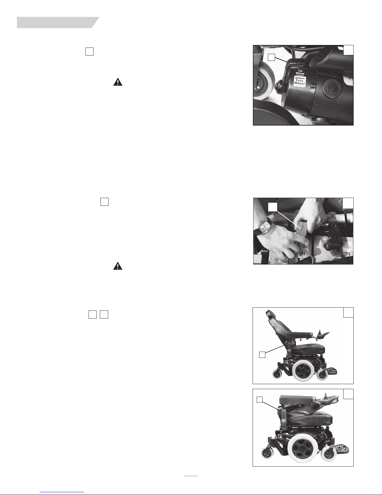
QUI CK IE PU LS E
VIII. USE AND MAINTENANCE
Q. MOTOR LOCK
Disengage the Motor Lock when you need to manually push the chair. (For example, in an
emergency, or if batteries fail).
20
WARNING
1. Do not disengage Motor Lock unless chair power is off.
2. With either one or both locks released, the chair will not operate and the battery
charge indicator will flash 9 bars rapidly (if power to the chair is on.)
3. Be aware that the chair will not have brakes in the free-wheel position.
4. Make sure that the person pushing the chair has full control when Motor Lock lever is
disengaged.
1. Disengage the Motor Lock to push the chair manually
a. The Motor Lock lever (A) is attached to the rear section of the motors located
towards the back of the chair.
b. Push the Motor Lock lever down to disengage.
2. Engage the Motor Lock to drive the chair
a. The Motor Lock (A) is attached to the upper rear section of the motors located at
the back of the chair.
b. Pull the lever up to engage the Motor Lock.
R. BATTERY REMOVAL
1. To remove the batteries before transporting or servicing:
a. Carefully flip back the seat (see Section XI T Seat removal)
b. Remove the shroud (see Section XI E Shroud removal) .
c. Unplug the main power connect (B)
d. Lift the batteries out of the frame using the battery strap as a lifting handle.
2. Battery installation
• See section X. (Batteries) for installation
21
20
A
B
21
WARNING
Batteries may weigh up to 39 lbs. Care must be taken to avoid injury when lifting up on battery straps.
S. CAPTAINS SEAT
The Captains seat back can be manually reclined, folded, or angle adjusted.
1. Adjusting the recline angle
a. To adjust, pull up on the release lever(C) located on the right side of the backrest.
b. Reposition the backrest forward or backward to the desired position.
c. Release the lever (C) and wiggle the backrest to make sure it locks in place.
2. Folding the Back (unoccupied)
a. To fold, Pull up on the release lever(C) located on the right side of the backrest.
b. The backrest should spring forward into the folded position as shown.
c. Release the lever.
d. To unfold the back, pull up on the release lever (C) and adjust the back to an upright
position.
2322
22
C
23
C
119832Rev. G
20
Page 21

QUI CK IE PU LS E
T. CHECK-OUT
Once the wheelchair is assembled and adjusted, it should roll smoothly and easily. All
accessories should the checked to make sure they are also performing smoothly. After the
heelchair has been set-up, be sure that the chair performs to ytour specified operational
w
settings.
If the chair does not perform the way you expect it to, (according to specifications), turn
your wheelchair OFF immediately and contact your authorized supplier to re-program operational settings using the RNET or VR2 operating guide.
If you have any problems, follow this Procedure:
a. Review the Set-up, Adjustment, and use section and the Operating Guide to make
sure the chair was properly prepared.
b. If your problem persists, contact your authorized supplier. If you still have a problem
after contacting your authorized supplier, contact Sunrise Medical Customer service.
See the introduction page for details of how to contact the people who can help you.
VIII. USE AND MAINTENANCE
21
119832 Rev. G
Page 22

QUI CK IE PU LS E
IX. CONTROLLER, JOYSTICKS & OPERATING GUIDE
Profiles and modes explained
The operation of the R-net system is based around the concept of Profiles and Modes.
A Profile is a collection of programmable parameters that affect the operation and performance
of the wheelchair. It is typical to have 5 Profiles, each set-up to give a different driving performance. For example, Profile 1 may have very slow settings for speeds and accelerations, while
rofiles 2 through to 5 would have progressively faster settings. In this way, the user can change
P
the performance of the wheelchair by selecting the appropriate Profile with the Profile Button
on the JSM. Although Profiles are used mainly to change driving performance, they can also contain parameters for other functions, such as seating control.
A Mode reflects the actual operation that occurs as a result of a joystick command. Typical
xamples are Drive Mode, Seating Control Mode and Bluetooth Mode. The user can select the
e
required Mode with the Mode Button on the JSM. Note, it will only be possible to select a
Mode if there is a Module that will support that Mode connected into the system. For example,
if there is no Mouse Module connected, then the user will not be able to select that Mode.
A. CONTROLS
Omni Input Display
The Omni input display is a universal specialty controls interface that accepts signals from
many different types of SIDs and translates them into commands compatible with the PG
Drives Technology RNET control system.
B. CONNECTORS
Mating Connectors
To connect the communication cables (A):
Holding the connector housing, firmly push the connector into its mate until you can
no longer see the yellow plastic. The connectors are secured using a friction system.
To disconnect the communication cables:
Holding the connector housing firmly, pull the connectors apart.
NOTE
– Do not hold or pull on the cable. Always grip the connector when connecting and
disconnecting.
When the control system is first switched on after a connection, or system component
change, the timer will be displayed while the system checks itself. Then the re-start icon will
be displayed. Switch the control system off and on again to operate,
24
2625
CD
L
creen
s
Profile
Mode
Power
Module
O
On/Off
mni Display
JOYSTICK
A
+/-
Navigation
2
25
26
4
C. R-NET JOYSTICKS
Controls:
Joystick key:
LED, Color Display, and Advanced Joystick
LCD Screen (B), Paddle Switch (Left and Right) (C), External Profile Jack (D),
External On/Off Switch Jack (E).
27
WARNING
Cleaning the LCD screen (B)
ALWAYS
1.
2. To clean fingerprints and greasy smudges off of your LCD screen use a screen cleaning solution that is designed for LCD screens (Non-ammonia based). Put a small
amount of the solution on a clean, lint free, dry cloth and rub the screen gently.
NEVER
3.
solvents such as alcohol, benzene, ammonia, or paint thinner.
NEVER
4.
strip the anti-glare coating off of the screen and cause permanent damage to the
Joystick screen.
119832Rev. G
use a soft, clean, lint free, dry cloth
use any type of windex cleaner, soap, scouring powder, or any cleanser with
use abrasive pads or paper towels. If you do, you can scratch the screen or
22
Advanced Joystick shown
C
B
27
D
E
119832 Rev. D
Page 23

QUI CK IE PU LS E
IX. CONTROLLER, JOYSTICKS, & OPERATING GUIDE
D. JOYSTICK BUTTONS AND CONTROLS
Battery Indicator
A
302928
This displays the charge available in the battery and alerts the user when the charge level is low.
• Steady: This indicates that all is well
• Flashing Slowly: The control system is functioning correctly, but you should charge the
battery as soon as possible.
• Stepping Up: The wheelchair batteries are being charged. You will not be able to drive
he wheelchair until the charger is disconnected and you have switched the conrol
t
system off and on again.
• If the battery gauge shows red, yellow and green, the batteries are charged (bars 1 - 10).
• If the battery gauge shows just red and yellow, then you should charge the batteries
as soon as you can (bars 1 - 7).
• If the gauge shows red, then you should charge the batteries immediately (bars 1 - 3).
On/Off Button
B
The on/off button applies power to the control system electronics, which in turn supply
power to the wheelchair’s motors. Do not use the on/off button to stop the wheelchair.
Horn Button
C
The horn will sound while this button is depressed.
Actuator Indicator
D
This LED set displays which actuator channel is currently being controlled when the control
system is in Actuator Mode. Actuator selection and operation is achieved using the joystick.
• Motions to the LEFT or RIGHT select different actuator channels.
• Motions FORWARD and BACKWARD move the actuator(s) selected.
Mode Button
FE
The Mode button allows the user to navigate through the available operating modes for the
control system. The available modes are dependent on programming and the range of auxiliary output devices connected to the control system.
Maximum Speed/Profile Indicator
G
This is a gauge that shows the maximum speed or profile setting of the wheelchair. There
are five speed/profile settings– step 1 is the lowest speed and step 5 is the highest.
• Speed level active is indicated on display by a series of five lights. One light indicates
slowest level currently active, while five lights indicates highest level currently active.
• Drive mode is indicated by a single light. The first light indicates Drive Mode 1; the
second light indicates Mode 2, and so on.
Speed Increase / Decrease Button
H
These buttons Increase or decrease the maximum speed setting. If the control system is
programmed for drive profile operation, the buttons select a lower or higher drive profile.
LED
Color
28
29
A
B
C
D
E
F
G
H
Screen Side buttons
I
These buttons operate lighting functions: Hazards, lights, left and right indicator. Once the
function is activated, the icon will appear on the screen.
• If no lighting system is fitted, the buttons will be inactive.
• In all instances, the top left button, when held for a short time, will open the settings
menu.
Left Paddle switch
J
Power On/Off, (Do not use this to stop the wheelchair)
Profile/Mode: Allows the user to navigate thru the available drive profiles and modes.
Right Paddle switch
K
This button increases or decreases the maximum speed setting. A momentary screen may
be displayed when the paddle is operated. Depending on the programming, the paddle
switch can act as a momentary speed control, or as a continuous speed control.
23
30
I
J
K
119832 Rev. G
Page 24

QUI CK IE PU LS E
IX. CONTROLLER, JOYSTICKS, & OPERATING GUIDE
E. LCD SCREEN (color and advanced)
This section covers those joystick modules that are fitted with a color LCD screen. The
color LCD screen is split into three areas of information. The Top Bar, the Text Bar and
the Main Screen Area.
TOP BAR (A)
Battery Indicator:
isplays the charge available in the battery and alerts the user when the charge level is low.
D
Steady: Indicates that all is well.
•
• Flashing Slowly: The control system is functioning correctly, but you should charge the
battery as soon as possible.
• Stepping Up: The wheelchair batteries are being charged. You will not be able to drive
the wheelchair until the charger is disconnected and you have switched the control
system off and on again.
• If the battery gauge shows red, yellow and green, the batteries are charged (bars 1-10).
• If the battery gauge shows just red and yellow, then you should charge the batteries
as soon as you can (bars 1-7).
• If the battery gauge shows just red, then you should charge the batteries immediately
(bars 1-3).
32
31
MAIN DRIVE SCREEN (B) (color and advanced)
Profile Name
A text string that displays the name of the currently selected profile.
Clock
Displays the current time in a numeric format.
33
34
A
B
C
Color
Indoor-drive
14:35
31
32
33
34
35
36
Color Joystick Speed Display
Gives a proportional display of the wheelchair’s speed.
Maximum Speed Indicator
Displays the current maximum speed setting.
Digital Speed Display
Displays the actual speed of the wheelchair derived from the motors.
Advanced Joystick Speed Display
Gives a proportional display of the wheelchair’s speed.
Odometer
Displays the distance driven by the wheelchair. The display can show either the total distance or the trip distance, in miles or kilometers. The Settings Menu contains an option that
sets whether the trip or total distance is displayed, as well as a facility to reset the trip distance. If Latched operation is active, then that symbol will take priority over the odometer.
Advanced Joystick Max speed indicator
Displays the current maximum speed setting.
39
37
35
36
38
40
TEXT BAR (C) (color Joystick)
Current Profile
The currently selected profile is shown in numeric form or may be displayed as text.
Temperature warnings may also be displayed on this bar.
31
Advanced
1.55 mph
999 m
37
38
39
40
119832Rev. G
24
Page 25

QUI CK IE PU LS E
IX. CONTROLLER, JOYSTICKS, & OPERATING GUIDE
IMPORTANT ICONS AND MESSAGES (color and advanced)
Latched
When the control system is operating in a Latched condition this symbol will be displayed.
Inhibit
If the speed of the wheelchair is being limited; for example, by a tilted seat, then this orange symbol
will be displayed. If the wheelchair is being inhibited from driving, then this red symbol will be flash-
ng.
i
MODE SCREENS:
Actuator (Seating) Mode
Displays the sections of the chair currently selected for movement, the name given to the selection
and a direction arrow showing what sort of movement is available.
Speed Adjust
When Speed Adjust Mode is entered, this screen will be displayed momentarily.
Color Joystick Message Window
The RNET displays warning icons and informational messages, in a dedicated message window.
Advanced Joystick Message Window
The RNET displays warning icons and informational messages, in a dedicated message window.
41
42
43
44
45
46
41
42
43
44
45
46
Restart
When the control system requires a reboot; for example, after a module re-configuration, this
green symbol will be flashed.
E-Stop
If the External Profile Switch is activated during drive, or actuator operation, this red symbol will be
displayed.
Joystick Displaced
If you operate the Joystick before or just after you switch the control system on, the screen will
flash the joystick displaced screen.
You must release and center the joystick to resume normal operation. If you do not release the
joystick within five seconds the wheelchair will not be able to move, even if you release the joystick
and operate it again. The screen will display a diagnostic screen at this time. You can reset this condition by switching the control system off and on again.
Control System Locked
The control system can be locked in one of two ways. Either using a sequence of deflections and
presses with the Joystick, or with a physical key. How the control system is locked depends on
how the wheelchair manufacturer has programmed it. Refer to the R-Net technical manual
SK77981- Programming chapter for more details.
MOMENTARY SCREENS
If the momentary screens are programmed to be displayed, then pressing the Speed or Profile
Buttons will display screens such as this.
47
48
49
50
51
47
48
49
50
51
DIAGNOSTIC SCREEN
When the control system safety circuits have operated and the control system has been prevented
from moving the wheelchair, a diagnostics screen will be displayed. This indicates a system trip, i.e. the
RNET has detected a problem somewhere in the wheelchair’s electrical system.
52
25
52
119832 Rev. G
Page 26

QUI CK IE PU LS E
IX. CONTROLLER, JOYSTICKS, & OPERATING GUIDE
F. PERFORMANCE CONTROL SETTINGS
NOTE– BEFORE attempting to check and/or adjust settings on your joy-
stick, be sure to see your Dealer or Clinician and have them
make the adjustments if needed.
1. It is vital to match control settings to your level of function
and ability.
2. Consult your health care professional and your Authorized
Dealer to select the best control settings for you.
3. Check and adjust the settings every six to twelve months.
WARNING
Adjust the control settings immediately if you notice any change in
your ability to:
• Control the joystick.
• Avoid running into objects.
G. ON BOARD PROGRAMMER (DIAGNOSTIC
TEST TOOL) OR RNET PC PROGRAMMER
(Optional)
WARNING
Program settings beyond the ability of the user can result in serious injury. Consult your health care advisor before you alter settings.
The On-board Programmer or RNET PC Programmer lets you
adjust the control settings of the QM-710. Listed below are a few
of the many settings that can be adjust via the On-board
Programmer or RNET PC Programmer. (See RNET OBP Owners
Manual for full programmable parameters.)
• acceleration rate
• deceleration rate
• turn acceleration
• turn deceleration
• forward speed (max & min)
• reverse speed (max & min)
• turn speed (max & min)
• steer correct
Programming the Chair:
a. Access via DTT (Diagnostic Test Tool), or the PC
Programmer require an inline
connection to the communication cable.
b. Program as needed.
c. Remove Dongle or recycle power.
NOTE–
Review the RNET OBP Owner’s Manual for more details on how
to program your chair.
H. CTRL+5 ASSIGNABLE BUTTONS
The Ctrl+5 (Canbus switch) is a device that plugs into the PG
Drives R-net system and allows for the set up of up to ten different functions into the ten discrete buttons, (each toggle switch is
two buttons). This device uses the Sunrise Medical patented
Assignable Buttons feature. The Ctrl+5 switches are pre-programmed from the factory to default values for the actuators on
the chairs. Using the Dealer PC Programmer and dongle, the button assignments can be changed to any of the Assignable Buttons
functions to suit the user just like the joystick buttons.
I. JOYSTICK STATIONARY
Your chair has an available programming feature called “Joystick
Stationary” which can be set by your dealer. This feature senses
hen the joystick is displaced from neutral, yet left in a steady posi-
w
tion for a predetermined period of time. The controller will automatically turn off if the set time has been reached. This feature is
designed to protect the user, batteries and electronics if the joystick
is inadvertently displaced. There are two parameters that can be
adjusted:
Joystick Stationary Time
1.
This is the time the joystick has to remain within the stationary range before the unit will come to a stop. It can be
programmed from 0 to 60 minutes in steps of one minute.
elect 0 to disable the function. Default setting is 0
S
(Disabled).
Joystick Stationary Range
2.
This determines the size of a region around the present joystick position. If the joystick remains within this region for the
stationary time the controller will stop. The range can be programmed from 1 to 50, in steps of 1. Default setting is 1.
:
:
WARNING
Before turning on or adjusting these parameters, carefully read
and understand the implications for use of these features, Joystick
Stationary Time and Joystick Stationary Range. When the “Joystick
Stationary Time” is reached within the “Joystick Stationary Range”,
the drive motors on the chair will shut off. As an example, this will
happen while driving in a straight line for extended periods of time
with no joystick movement. Once the drive motors turn off, the
user will need to turn the chair off and back on to drive.
J. THERMAL ROLL-BACK
Your chair has a thermal roll back circuit. This protects the controller from damage due to overheating. In extreme conditions (such
as repetitive hill climbing) the circuit will decrease the power to your
motors. This allows the chair to operate at a reduced speed. When
the controller cools, the chair will return to normal speed.
K. RECLINE, TILT & LIFT OPERATION
The tilt and lift features on your chair can all be operated using the
joystick on your chair. Follow the instructions below to operate:
If the thru drive option was selected,
1. Make sure your controller is on.
2. From the Drive Mode, press the Mode button to enter
Power Seating Mode.
3. Move the joystick left or right selecting the power option
(recline, tilt, lift, legrests) you wish to control.
4. Move the joystick forward or backward to adjust the selected power option to the desired position.
5. Press the Mode button to return to normal operation or
continue moving the joystick left or right to adjust the next
power option. Multiple Mode button presses will be necessary if other modules, such as Output, are active.
A
53
53
119832Rev. G
26
Page 27

QUI CK IE PU LS E
IX. CONTROLLER, JOYSTICKS, & OPERATING GUIDE
L. VR2 JOYSTICK
The standard VR2 joystick controls the chair’s performance. It consists of the following
parts:
1. Speed Control or Drive Mode Selection Buttons (A, B and C)
a. To decrease the speed level depress button(A). Or, when 1- 5 Drive modes are pro-
rammed, depress button A to activate lower drive mode(s).
g
b. To increase speed level, depress button (B). Or, when 1- 5 Drive modes are pro-
grammed, depress button B to activate higher drive mode(s).
c. Speed level active is indicated on display (C) by a series of five lights. One light indi-
cates slowest level currently active, while five lights indicates highest level currently
active.
d. Drive Mode is indicated by a single light. The first light indicates Drive Mode 1; the
second light indicates Mode 2, and so on.
2. Battery Charge Indicator (D)
Displays the charge available in the battery and alerts the user when the charge level is low.
• Steady: Indicates that all is well.
• Flashing Slowly: The control system is functioning correctly, but you should charge the battery as soon as possible.
• Stepping Up: The wheelchair batteries are being charged. You will not be able to drive the
wheelchair until the charger is disconnected and you have switched the control system off
and on again.
• If the battery gauge shows red, yellow and green, the batteries are charged (bars 1-10).
• If the battery gauge shows just red and yellow, then you should charge the batteries as
soon as you can (bars 1-7).
• If the battery gauge shows just red, then you should charge the batteries immediately (bars 1-
3).
3. On/Off Button (E)
Turning the chair on or off is accomplished by depressing button E.
54
C
A
D
F
B
VR2 Joystick
I
H
VR2 Joystick with Actuator Control
54
E
55
G
4. Horn (F)
5. Joystick (G)
The joystick controls the direction and speed of your chair. Turn the chair on and move the
joystick in the direction you want to go.
• Moving the joystick from the neutral (center) position disengages the motor brakes,
allowing the chair to move.
• The chair will move faster the more you move the joystick away from neutral.
NOTE–
If your speed becomes hard to manage, release the Joystick and the chair will come to a com-
• When you release the joystick it will return to neutral; the chair will slow to a stop
and the motor brakes will reengage.
• We recommend that you switch the chair off if you stop for any length of time. This
will conserve battery power.
NOTE–
Once the chair stops, switching the chair off will not affect the motor brakes.
6. Joystick Boot (H)
Make sure the boot is not torn or cracked (this could allow debris, water or moisture to
enter). If the boot is torn or cracked, replace it as soon as you can.
7. Tilt or Lift Control (SC only) ( I )
This button once depressed allows you to control the up and down movement of the tilt/lift.
Press button “I”. Then push the joystick forward to tilt/lift the seat upward or pull the joystick
back to tilt/lift the seat downward. Pressing button “I” again will allow drive operations to
resume.
55
plete stop.
55
55
27
119832 Rev. G
Page 28

QUI CK IE PU LS E
A. INTRODUCTION
1. Notes–
• Batteries supply the power for your chair. They contain a
finite amount of energy and have limits on how long they can
store and supply energy.
You can charge batteries only a certain number of times
•
before they will fail and no longer hold a charge.
• For answers to questions about batteries, consult your
Authorized Dealer.
2. Use Proper Batteries:
Your chair operates on two 12 volt batteries.
• They should be Group 22 batteries.
• When you buy a replacement, insist on a
case
type. Do not use a car or boat battery.
3. Breaking In:
• A battery requires “breaking-in” for the first 6 to 12 charges.
It will not accept a full charge for this period.
• It is best to limit the length of your trips until you break the
batteries in and you know the range of your chair.
4. Discharged Batteries:
Never
•
•
•
allow a battery to completely discharge. If you operate
your wheelchair until it has almost stopped, you will greatly
reduce the life of your batteries.
Never
let a battery sit in a discharged condition. Give unused
or stored batteries a full charge once per month.
Always
fully charge the batteries.
not necessary.
Avoid
deep cycle sealed
charging when it is
WARNING
Never connect a life support or auxiliary device to a wheelchair battery. The electrical system may fail, and result in severe injury to or
death of the user.
B. CHARGING BATTERIES
56
WARNING
To avoid risk of severe injury or death from electrical shock, fire or
explosion while charging. Never connect charger to a 240 volt
source. The main input voltage is 110 volts. Never touch the
charger after it is connected to an electrical outlet.
Never
1.
2.
3. A battery can emit explosive hydrogen gas if the wrong charg-
ALWAYS:
4. Use the charger that comes with your wheelchair. Read and
connect or disconnect charger from battery while
there is power to the charger.
Never
use an extension cord. Use of an improper cord could
damage the charger or cause a fire or electrical shock.
er is used. To reduce the risk of fire or explosion:
• Make sure area is well vented. Never charge battery in a
closed-in area.
• Never smoke or allow a spark, flame or high heat near bat-
tery during charging.
• Never allow metal tools or chair parts to make direct con-
tact across both battery terminals.
follow all instructions and warnings. Make sure the room is
well ventilated. Turn off all power to your chair.
X. BATTERIES
NOTE–
Always remove and reattach the negative cable (black cable)
irst.
f
NOTE–
Batteries should never be left for long periods in the dis-
charged state. Unused or stored batteries should be given a
harge once per month.
c
5. Make sure to allow enough time to fully charge batteries.
. To charge batteries, use the off-board charger by plugging off-
6
board charger plug into the off-board charger socket.
C. BATTERY CHARGER
A battery charger produces a direct current (DC). When applied to
a discharged battery, this reverses the chemical reaction that led to
its discharge.
1. Charge Rate. How fast a battery will charge depends on:
• Its electrical capacity; state of charge; electrolyte tempera-
ture, and; internal condition.
• The DC output of the charger. (The charge rate will vary if
the alternating current (AC) supply is higher or lower than
110 volts).
2. Caution — To Avoid Damage to the Charger:
• Never place the charger on top of a battery during charging.
(Gases from the battery can damage the charger and may
lead to an explosion or fire).
Never
•
•
• Never unplug charger by pulling on the electrical cord. This
•
• Keep cord out of the way, where it will not be stepped on,
3. Caution — To Avoid Damage to the Battery:
• Make sure you use the correct setting for sealed (gel) batter-
•
place a battery on top of the charger.
Never
expose charger to rain or snow.
will damage the cord.
Never
open a charger or attempt to repair it yourself. Return
charger to Sunrise or have repairs made only by a qualified
person.
tripped over, or damaged.
ies (located on the off-board charger).
Never
charge a frozen battery. A fully charged battery will
rarely freeze, but the fluid in a discharged battery can freeze
at 16 degrees Fahrenheit (minus 9 degrees Centigrade). If you
suspect a battery is frozen, thaw it before charging.
56
Off-board charger port
located under joystick
119832Rev. G
28
Page 29

QUI CK IE PU LS E
Battery 1
Neg. Term
Battery 2
Neg. Term
Battery 1
Pos. Term
Battery 2
Pos. Term
X. BATTERIES
D. CONNECTING BATTERIES
57
WARNING
1. Batteries weigh up to 55 lbs. Take care to avoid injury when lifting.
2. Always wear rubber gloves and safety glasses when you handle batteries.
3 Before working with batteries, remove all metal effects, such as necklaces, rings,
watches, pins and other metal jewelry that might contact battery terminal and
cause a short.
1. Replacing the Batteries
1. Lift batteries into battery compartment.
2. Attach the battery harness to the battery post. Connect red to the positive terminal
and black to the negative terminal.
. Cover the battery posts with insulating caps on the harness.
3
WARNING
Connect and disconnect battery cables with caution. Do this for each battery. Tighten all
terminal fasteners using two 1/2" box end wrenches to 60 in-lbs (6.8 N.m).
direct contact across both battery terminals, as an explosion may occur. A spark may result
in an explosion and/or fire resulting in severe injury or death.
E. BATTERY MAINTENANCE
58
Never
make
WARNING
1. Fire or sparks
a. Never smoke or hold an open flame near batteries.
2. Protect your skin and clothes
a. Always wear rubber gloves and safety glasses when you handle batteries.
3. Corrosion:
Check battery terminals often for corrosion.
a. If corrosion is present, use a wire brush to clean the terminals.
b. Use petroleum jelly to re-grease the terminals after connecting cable to battery.
(Completely cover the terminal nut and bolt, cable clip and any exposed cable with
jelly).
4. For Answers To Questions about batteries: Contact your authorized dealer.
A
57
58
F. DISPOSING OF BATTERIES
WARNING
1. All batteries once they have reached the end of their useful life are deemed to be hazardous waste.
2. For further information on handling and recycling contact your local
recycling authority.
3. Always dispose of product through a recognized agent.
G. FUSES
Your Pulse has two inline fuses.
• In the unlikely event of a short circuit or other fault, all power to your
chair will be shut off to protect your motors and controller from damage.
• Qualified service personnel are required to repair the fault and replace the
battery harnesses.
H. BATTERY WIRING DIAGRAM
59
59
29
119832 Rev. G
Page 30

QUI CK IE PU LS E
WARNING
The owner of this chair is responsible for making sure that it has been setup and adjusted by a trained
service professional under the advice of a healthcare Professional. Service or adjustments should only
be done with the advice of a Healthcare Professional. Always use parts and accessories that have been
recommended and approved by Sunrise Medical when servicing this chair.
XI. DEALER SERVICE & ADJUSTMENT
0
6
A. DEALER SERVICE INTRODUCTION
1. At least once per year, this chair should have a complete inspection, safety check, and regular
service made by an authorized dealer. The tool list at right is a good starting point for proper
maintenance.
2. If you have discovered a worn, bent, or damaged part, repair or replace them with recommend-
3. All major maintenance and repair work should be done by the Authorized Dealer.
before returning this chair to service.
ed parts
60
.
B. CRITICAL MAINTENANCE TIPS
1. Torque settings:
A torque setting is the optimum tightening which should be made on a particular fastener. It is important to use proper torque settings where specified. When not specified, torque settings should be set
at a minimum of 60 in-lbs.
2. Dealer Service and Adjustment Reference materials:
Go to www.sunrisemedical.com for parts manuals, instruction sheets, and instructional videos that will
aid in the repair of the Quickie Family of wheelchairs.
C. CLEANING
1. Paint Finish
a. Clean the painted surfaces with mild soap or detergent.
b. Protect the paint with a coat of non-abrasive auto wax.
2. Axles and Moving Parts
a. Clean around axles and moving parts with a slightly damp (not wet) cloth.
b. Wipe off or blow away any fluff, dust or dirt on axles or moving parts.
c. DO NOT USE 3 in 1 oil, or WD-40 ® for lubrication. Only use Teflon based Lubricant when
working on this wheelchair.
TOOLS YOU WILL NEED
1. Imperial Hex key set
2. Metric Hex key set
3. Imperial Open-end Wrench set
4. Metric Open-end Wrench set
5. Torque wrench
6. Imperial Hex bit Socket set
7. Metric Hex bit Socket set
8. Phillips and Flat screwdrivers
D. ADJUSTMENT NOTES
1. Work Surface For Set-Up:
Use a flat surface, such as a table, to assemble, adjust and check your chair. This makes the
steps easier and helps ensure a correct set-up.
2. Fasteners:
• Many of the screws and bolts on this chair are special high-strength fasteners and may
have special coatings.
• Many nuts are of the Nylock type. They have a plastic insert to help prevent loosening.
• Only use screws, bolts and nuts provided by Sunrise.
WARNING
1. Use of improper fasteners may cause the chair to fail.
2. Over- or under-tightened fasteners may fail or cause damage to chair parts.
3. If bolts or screws become loose, tighten them as soon as you can. Loose bolts or
screws can cause damage to other chair parts causing them to fail.
3. Washers & Spacers:
• Note the position of washers and spacers before disassembly.
• To avoid damage to the frame, replace all washers and spacers when you reassemble
parts.
119832Rev. G
30
Page 31

QUI CK IE PU LS E
E. SHROUD REMOVAL
The plastic protective shroud can be removed for adjustment or servicing.
1. Remove the top shroud
a. Remove the Seat (Section T previous page).
. Remove the six screws(A) that hold the shroud to the frame.
b
c. Once all of the screws have been removed, the shroud should be free to remove.
61
XI. DEALER SERVICE & ADJUSTMENT
6
1
A
2. Remove the rear shroud
a. Remove the two rear shroud screws.
b. Pull downward at the top of the rear shroud, then lift up and off.
3. Replacing the front, or rear shroud
a. Position the shroud and hand thread a few screws to hold the shroud in place.
b. You can then insert the other screws while moving the shroud to line up the holes.
c. Be sure not to tighten screws too much, because it could fracture the plastic.
F. BATTERY REMOVAL
1. To remove the batteries before transporting or servicing:
a. Carefully flip back the seat (see Section T Seat removal)
b. Remove the shroud (see Section E Shroud removal) .
c. Unplug the main power connect (B)
d. Lift the batteries out of the frame using the battery strap as a lifting handle.
2. Battery installation
• See section X. (Batteries) for installation
62
63
WARNING
Batteries may weigh up to 55 lbs. Care must be taken to avoid injury when lifting up on battery straps.
6
2
B
63
G. SINGLE POST HEIGHT-ADJUSTABLE ARMRESTS
1. Adjusting armrest receiver (forwards or backwards)
a. Loosen the 3 bolts (C) on the receiver clamp.
b. You can move the armrest and receiver forwards or backwards for a universal fit.
c. Tighten the hardware when adjustment is complete(C).
2. Adjusting Armrest Receiver Fit (tighten or loosen fit)
To tighten or loosen the fit of the outer armpost in the receiver:
a. Loosen the four bolts (D) on both sides of the receiver.
b. With the armrest in the receiver, squeeze the receiver to achieve the desired fit.
c. Continue the pressure on the receiver and tighten the four bolts.
3. Adjusting Inner Armpost Fit
a. Two set screws(E) are installed in the outer armpost.
b. Turn the set screws in or out until the desired fit is achieved.
(Optional)
31
64 65
64
C
D
65
E
119832 Rev. G
Page 32

QUI CK IE PU LS E
XI. DEALER SERVICE & ADJUSTMENT
H. CANTILEVER ARMRESTS
1. Adjusting Armrest Pad (forwards or backwards)
a. Loosen the 2 bolts (A) on the armrest pad bracket.
b. You can move the armrest and receiver forwards or backwards for a universal fit.
c. Tighten the hardware when adjustment is complete.
2. Adjusting Armrest Angle or levelling the armrest after height adustment.
a. Loosen the pivot bolt (B) on the armrest angle bracket.
. Remove the Socket head screw and hardware. (C)
b
c. Adjust the angle of the armrest and joystick and re-insert the hardware thru the
adjusted hole.
d. Tighten all hardware when adjustments are complete.
3. Adjusting Armrest Height
a. Locate the height adjustment screw (F) at the bottom of the cantilever arm and adjust
the height by using a 5mm hex key and turning the screw either clockwise (more
height), or counter-clockwise (less height).
b. Do not loosen the screw to the point where it will fall out of the armrest. If this hap-
pens simply re-thread the screw into the armrest until it starts to height adjust the
armrest again.
c. When you reach desired height remember to level the armrest using screws (D) and
(E) as shown in step 2 above.
NOTE– The cantilever armrest has about 2” of adjustment set from the factory. In most cases the
external height adjustment will be all that is necessary for a proper fit
(Optional)
(within factory limits)
66 67
66
A
B
C
67
D
E
F
I. RETRACTABLE JOYSTICK MOUNT
The Retractable Joystick Mount can swing in/out in increments of 45°, 90°, and 135°
1. Height adjustment
a. Remove the Joystick mount (G) by removing hardware (H).
b. Flip bracket ( I ) upside down and re-attach the Joystick mount assembly components
c. Replace and retighten bolts on each side.
J. MIDLINE JOYSTICK MOUNT
The Midline Joystick Mount has 3 axis adjustment, and can be rotated out of the way.
1. Left, Right, Center adjustment
a. Loosen the clamp screws ( J ) and move the joystick laterally in front of the rider.
b. After finding the most comfortable adjustment, make sure the Joystick is level.
c. Retighten the clamp screws.
2. Height adjustment
a. Loosen the clamp screw (K) and move the joystick vertically,
b. After finding the most comfortable adjustment, retighten the clamp screw.
69
68
68
I
H
G
69
J
K
119832Rev. G
32
Page 33

QUI CK IE PU LS E
XI. DEALER SERVICE & ADJUSTMENT
K. JOYSTICK CONTROLLER POSITION
The controller can be moved in or out in relation to the armrest. You can also move the
controller to either side of your chair to accomodate left or right-hand use.
70
WARNING
Be careful of pinching your controller cords.
and cord can be at risk of pinching from the Seat frame, and/or the Power base frame. Be
sure to route and secure the cord with a zip tie to avoid cord pinching,. Cord pinching
could eventually disable your power chair if left unchecked.
Before Moving the controller from one side to the other read these important tips.
a. Turn off the power to the controller.
b. Unplug the controller connectors from the power base.
c. Remove any wire ties securing the controller harness to the armrest.
d. Flip up the armrest so that it is perpendicular to the floor.
e. Loosen the hardware on the controller bracket and slide the controller out.
f. Re-tighten the hardware, so it won’t be lost accidentally.
g. Loosen the hardware on the other armrest.
h Slide the controller arm into the other armrest, and tighten the hardware.
i. Route and secure the controller harness to the back of the power base and plug in
the controller cord. Make sure to avoid any areas where the cord may be pinched.
Adjustment and/or switch sides.
a. To adjust the joystick, forward or back, loosen the clamp(A), move the joystick, and
then hand-tighten the clamp handle.
b. To move the joystick to the opposite side of the chair, remove the hardware(B) and
move the clamp and joystick receiver to the other armrest.
c. Tighten all hardware to avoid any movement of the joystick while travelling.
When the controller is moved, the harness
70
B
A
71
C
D
72
L. SWING-IN/OUT FOOTREST ADJUSTMENT
Footplate Height Adjustment
a. Remove the hardware(C) from the hanger frame tube.
b. Move the footrest extension tube(D) up or down to set the correct height, and line
up the adjusted holes.
c. Insert the hardware to hold the tube in place.
d. Re-tighten all hardware(C)
71
M. ANGLE ADJUSTABLE CENTER MOUNT HEIGHT ADJUSTMENT
(ASAP Seating only)
1. Quick Independent angle adjustment
a. Depress the button(E) and angle adjust the footplates as an assembly
b. The footplates can be moved independantly of each other by removing the bracket
(G) that locks the footplates together.
2. Footplate Height Adjustment
a. Loosen the securing screws (F).
b. You can move the footplates up or down to the desired height as an assembly or
adjust the height for each footplate independantly
c. Tighten the hardware(F)
N. ELEVATING LEGREST ADJUSTMENT
1. Footplate Height Adjustment
a. To raise footrest, loosen the two bolts( I ) that hold the extension tube and footplate
in place.
b. Adjust the footplate up or down for best adjustment, and tighten the hardware(H).
2. Calf pad Adjustment
a. Remove the securing screw ( I ).
b. Move Calf Pads to desired height.
c. Re-tighten the screws (H) through adjusted hole.
(Optional)
73
E
72
F
G
73
I
H
33
119832 Rev. G
Page 34
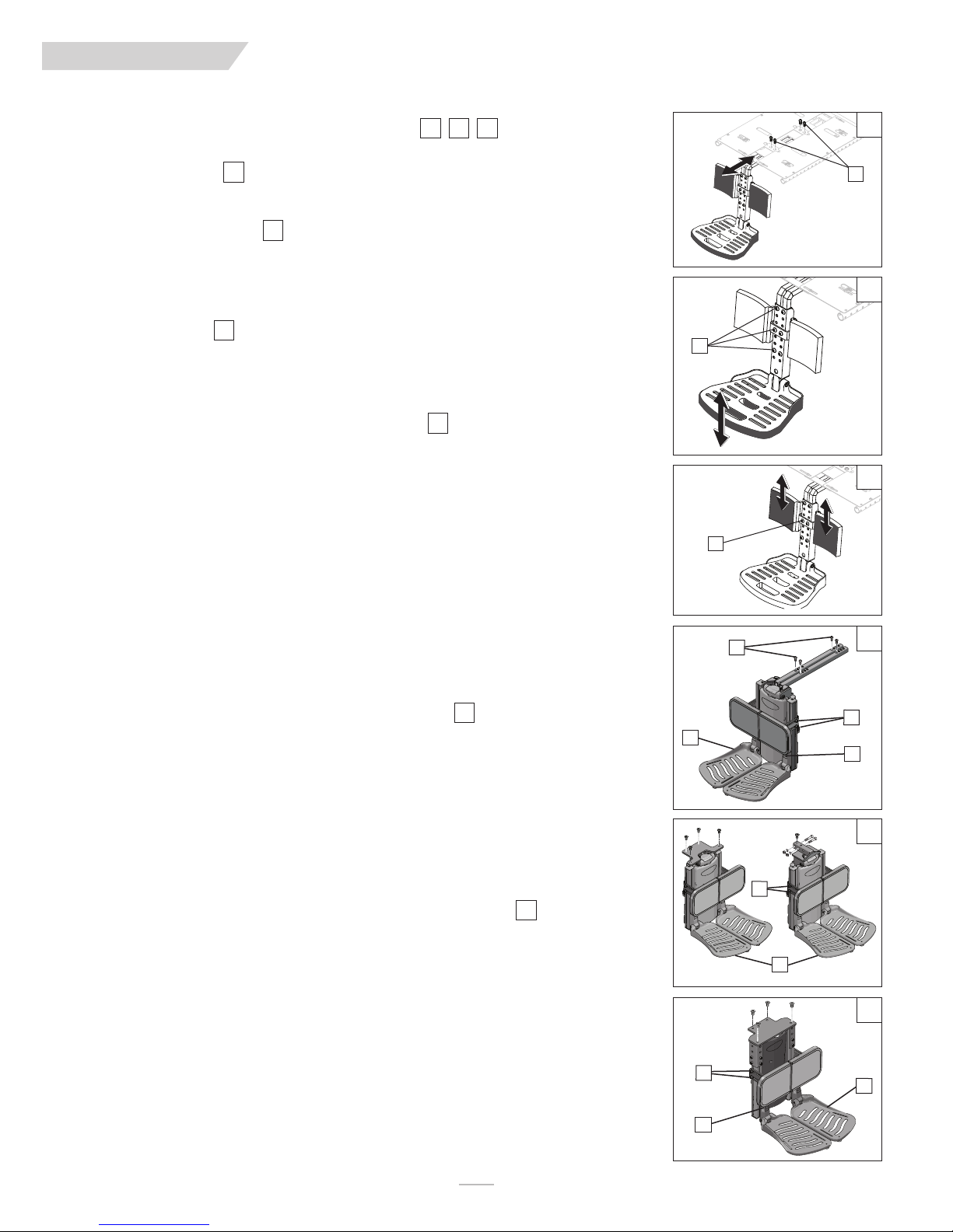
QUI CK IE PU LS E
O. CENTER MOUNT HANGER ADJUSTMENT
767574
(ASAP Seating only)
1. Removing the assembly
a. Remove the four screws (A) and slide the footrest assembly out of the receiver.
74
XI. DEALER SERVICE & ADJUSTMENT
4
7
A
2. Footplate Height Adjustment
75
a. Remove the six securing screws (B).
b. Move the footplate up or down to the desired height.
c. Re-install screws (B) through adjusted holes and tighten the hardware.
3. Calf pad Adjustment
76
a. Remove the two securing screws (C).
b. Move Calf Pads to desired height.
c. Re-install screws (C) through adjusted holes.
P. POWER CENTER MOUNT FOOTREST ASAP
77
1. Footrest Depth Adjustment (Not recommended)
a. Remove the hardware(D) from the support frame tubes.
b. Move the footrest assembly forward or back for depth adjustments
c. Insert the hardware to lock the adjustment in place.
d. Re-tighten all hardware.
2. Calfpad height, angle and depth adjustment
a. Using a 5mm hex key, loosen both screws(E) and adjust the calfpad to the desired setting.
b. Re-tighten the hardware.
3. Footplate Height Adjustment
a. The footplates (G) can be raised or lowered
b. Using a 5mm hex key loosen the two screws (F) at the top of the footrest bracket, and move
up or down to set the correct height.
c. Re-tighten the hardware to hold the adjustment in place.
75
B
76
C
D
77
Q. POWER CENTER MOUNT FOOTREST RECLINE
78
1 Calfpad height, angle and depth adjustment
a. Using a 5mm hex key, loosen both screws(E) and adjust the calfpad to the desired setting.
b. Re-tighten the hardware.
2. Powered Footplate Height Adjustment
a. The footplates (G) can be raised or lowered
b. Using a 5mm hex key loosen the two screws (F) at the top of the footrest bracket, and move
up or down to set the correct height.
c. Re-tighten the hardware to hold the adjustment in place.
R. FIXED CENTER MOUNT FOOTREST (POWER RECLINE)
79
1 Calfpad height, angle and depth adjustment
a. Using a 5mm hex key, loosen both screws(E) and adjust the calfpad to the desired setting.
b. Re-tighten the hardware.
2. Powered Footplate Height Adjustment
a. Using a 5mm hex key, loosen the screws (F) so that the footplates (G) can be raised
or lowered
b. Move the footplates up or down to set the correct height.
c. Re-tighten the hardware to hold the adjustment in place.
E
G
F
78
E
G
79
E
G
F
119832Rev. G
34
Page 35

QUI CK IE PU LS E
XI. DEALER SERVICE & ADJUSTMENT
S. SEAT DEPTH ADJUSTMENT
The seat depth can be adjusted in one inch increments on standard rehab seating.
1. Seat Frame Depth Adjustment
a. To adjust, remove the two bolts (A & B) from each side of the backrest pivot plate.
. Reposition the backrest to the desired position.
b
c. Replace and retighten bolts on each side of the backrest pivot plate.
2. Back Angle Adjustment on Seat Frame
a. Remove the front securing bolt (A) on the side of the backrest hinge plate.
b. Loosen the lower rear bolt (B)
c. Set at desired angle. There are five holes (in 4º increments) to choose from.
d. Reinstall the front bolt and tighten both bolts securely.
T. SEAT REMOVAL
Most adjustments that can be made to the ASAP II seating system, should be done with the
seating system removed from the base. Standard practice should be to remove the seating
system and place it on a workbench for an easier and safer adjustment.
a. Disconnect the joystick power cable (C) in the rear of the chair.
1. Seat tilt back (for quick access to battery compartment)
a. Remove the knobs (D) that attach the seat to the seat posts.
b. Tilt the seat back until it is resting on the work surface.
2. Seat removal (required to replace modules or adjust the seat width of the chair)
a. Remove the 4 screws (E) to detach the seat pan from the modules underneath. The
locations of the screws may vary depending on the size of the seating area, type of
module, and size of seat pan.
b. Remove the seat and place it in a stable work area.
10" - 18", 12" - 20" only
838281
80
80
B
A
8
1
C
82
D
U. SEAT PAN AND BACK SIZE ADJUSTMENTS
NOTE:
1. Seat Pan/Frame Width Adjustment
Your ASAP II seating system can be adjusted to a wide range of widths and depths
to accommodate specific user needs. Seating dimensions should only be altered
by a trained medical professional and may require a new seat pan, cushion and/or
stabilizer bar to complete the adjustment.
a. Most width adjustments require the back, stabilizer bar, and back brackets to be
loosened and/or removed before adjusting the seating width.
b. To adjust the width of the seating area, remove the screws (F) that attach the seat
pan to the seat frame (H).
c. Reposition (G) (either solid seat pan, or split-cover seat pan) to achieve the desired
width (1/2” increments on each side). Make sure that it is centered and equally spaced
from side to side.
d. For the 13” wide, (10x10-13x18 seat), you will need to mount the width fillers (H) to
cover the gap between the seat rail (H) and seat pan (G).
e. Check your width measurements and then replace and retighten all the hardware.
83
E
8584
84
I
119832 Rev. G
35
F
H
G
Page 36

QUI CK IE PU LS E
XI. DEALER SERVICE & ADJUSTMENT
2. Back Support Frame Width Adjustment
a. After measuring the width adjustment in the seating area, Remove the front securing
hardware (A) from the adjustment tube (B) on the stabilizer bar.
b. The Stabilizer bar can be adjusted in 1” increments(1/2’ on each side) to match the
width change in the seating area.
c. Replace the Stabilizer bar, recheck the measurement and make sure your backposts
are straight and parrallel. Tighten the adjustment screws (A)
V. SEAT HEIGHT ADJUSTMENT
a. After removing the seat, remove the lockout Pin (A) from all 4 seat mount posts.
b. In most cases, select the desired seat height by moving all four post up the same dis-
tance, so the seating system is level following the adjustment.
c. Reinsert the hardware and remember to replace the Lockout pin(A).
W. SEAT TO FLOOR HEIGHT/PRE-TILT POSITIONING
Your ASAP II seating system can be adjusted to many different seat to floor heights, and
pre-tilt positioning depending on your specific configuration. Seat to floor heights and Pretilt positioning should only be altered by a trained medical professional. For the correct
Pre-tilt settings and seat to floor heights, in relation to specific configurations of the Pulse
please Refer to the seat to floor matrix in the Pulse service manual before changing any of
the factory settings.
8584
86
8887
WARNING
DO NOT
seating pre-tilt.
NOTE
increase the front post height independent from the rear posts when providing
– For chairs configured with SPOT tilt, do not increase the Pre-tilt greater than 3 degrees.
For chairs configured with seat elevator, do not increase the Pre-tilt greater than 3 degrees.
For chairs configured with SPOT tilt and seat elevator, do not increase the seat-to-floor
height greater than 1” fron the lowest position.
For chairs configured with SPOT tilt and recline, do not increase the seat to floor height
greater than 18”, and do not increase the pre-tilt greater than 0 degrees.
Front Seat post
Hole 1
Hole 2
Hole 3
Hole 4
Hole 5
Rear Seat post
Hole A
Hole B
Hole C
Hole D
Hole E
A
85
B
8
6
A
87
88
119832Rev. G
36
Page 37

QUI CK IE PU LS E
1
2
4
3
5
6
8
7
9
5
6
8
7
9
1
2
4
3
XI. DEALER SERVICE & ADJUSTMENT
X. CAPTAINS SEAT
9089
1. Seat depth adjustments with 1” increments
a. Using a 5mm Hex Key, remove the M8 Flat head screws(A), (3 on each side)
b. Using a 5mm Hex Key, remove the M8 Flat head screws (B), (1 on each side)
. Using a 5mm Hex Key, loosen the M8 Flat head screws (C), (1 on each side)
c
d. While holding the backrest on each side, slide it front or back to achieve the desired
position.
NOTE–
Changing the seat depth can effect the balance of your chair. Test the chair careful-
ly before regular use if a seat depth adjustment has been made.
2. Seat depth mounting positions
a. Using the Seat depth mounting positions table, and the hole number callouts, refer-
ence the correct hole positions to achiever the desired width and depth.
89
C
B
A
90
3. Back height adjustments with 1” increments
NOTE–
There are 3 positions of adjustment in 1” increments for the back. Position 2 (+2)
91
(D), Position 1 (+1) (E), and position 0 (default) (F).
a. Using a 5mm Hex key, remove the M8 flat head screws (3) on each side.
b. Position the backrest at the desired height. The top screw should be mounted as
shown (figure 26).
c. Holding the backrest in place, tighten the screws.
d. Repeat the steps on the other side, and ensure that the left and right sides are posi-
tioned at the same height.
4. Armrest width adjustment
NOTE–
You can change the armrest widths independantly, remember that this adjustment
92
will increase the overall width of the wheelchair.
a. Locate the 2 armrest fasteners (G) on each side of the armrest receiver bracket.
b. Loosen the fasteners.
c. Slide the armrests in or out to the desired width.
d. Re-tighten the fasteners.
5. Armrest height adjustment
93
a. Using a 4mm Hex key, loosen the two M5 set screws(H) located on the armrest
receiver.
b. Raise or lower the armrest to the desired height.
c. Tighten the set screws to secure the armrest.
91
D
E
F
92
G
93
37
H
119832 Rev. G
Page 38

QUI CK IE PU LS E
XI. DEALER SERVICE & ADJUSTMENT
6. Armrest angle adjustment
a. Lift the armrest straight up so that it is perpendicular to the floor.
b. Loosen the jam nut (A)
c. Turn the adjusting screw (B) to raise or lower the front of the armrest.
d. Tighten the jam nut (A) to lock the adjusting screw into place.
e. Make sure that the set screws (C), and armrest knob (D) are tight when finished.
Y. CONTROLLER POSITION
You can move the controller in or out in relation to the armrest. You can also move the
controller to either side of your chair to accomodate either left-hand or right-hand use.
94
95
WARNING
Be careful of pinching your controller cords.
and cord can be at risk of pinching from the Seat frame, and/or the Power base frame. Be
sure to route and secure the cord with a zip tie to avoid cord pinching,. Cord pinching
could eventually disable your power chair if left unchecked.
1. Extending the controller
a. Flip up the armrest so that it is perpendicular to the floor.
b. Loosen the thumbscrew (E) on the controller bracket.
c. Slide the controller in or out of the armrest to the desired position.
d. Tighten the thumbscrews (E) to secure the controller.
When the controller is moved, the harness
94
B
A
C
D
95
E
Z. REPAIRING OR REPLACING A TIRE
96
WARNING
Residual air pressure in tires can cause severe injury. Make sure you release all air in tire
before attempting to service or repair tires.
1. Drive Wheels:
a. Elevate and securely support chair so that wheel is off the ground. Release all air from
tire.
b. Remove the three main lugnuts (F).
c. Remove the Drive wheel/tire assembly
2. Air Tube:
a. To replace the air tube, remove the six hex screws (G) so that the rims can be
seperated.
b. Seperate the two halves of the rim and remove tire and solid insert
f. Repair or replace.
g. Reassemble the wheel. Use a torque setting of 420 in-lbs to re-tighten the bolts.
h. Install the wheel on the chair using a torque setting of 180 in-lbs to retighten the
bolts.
i. Inflate the tire to the proper pressure level (listed on the tire sidewall)
96
G
F
119832Rev. G
38
Page 39

QUI CK IE PU LS E
XII. SUNRISE LIMITED WARRANTY
A. FOR FIVE (5) YEARS
Sunrise warrants the frame of this wheelchair against defects in
materials and workmanship for five years from date of first consumer purchase.
B. FOR ONE (1) YEAR
We warrant all Sunrise-made parts and components of this wheel-
hair against defects in materials and workmanship for one year
c
from the date of first consumer purchase.
C. FOR ONE (1) YEAR
We warrant all motors, gearboxes, batteries, and electronic components of this wheelchair against defects for one year from the
date of first consumer purchase.
D. LIMITATIONS
1. We do not warrant:
a. Tires and tubes, upholstery, pads and push-handle grips.
b. Damage from neglect, accident, misuse, or from improp-
er installation or repair.
c. Products modified without Sunrise Medicals express
written consent.
d. Damage from exceeding the weight limit.
2. This warranty is VOID if the original chair serial number tag
is removed or altered.
3. This warranty applies in the USA and Canada only. Check
with your supplier to find out if international warranties
apply.
4. This warranty is not transferable and only applies to the first
consumer purchase of this wheelchair through an authorized
Sunrise Medical dealer.
E. WHAT WE WILL DO
Our sole liability is to repair or replace covered parts. This is the
exclusive remedy for consequential damages.
F. WHAT YOU MUST DO
1. Obtain an authorized supplier, while this warranty is in
effect, prior approval for return or repair of covered parts.
2. Return the wheelchair or part(s), freight pre-paid, to Sunrise
Mobility Products Division at: 2842 Business Park Avenue,
resno, CA 93727-1328.
F
3. Pay the cost of labor to repair, remove or install parts.
G. NOTICE TO CONSUMER
1. If allowed by law, this warranty is in place of any other warranty (written or oral, express or implied, including a warranty of merchantability, or fitness for a particular purpose).
2. This warranty gives you certain legal rights. You may also
have other rights that vary from state to state.
H. ADDITIONAL WARRANTY INFORMATION
For goods provided by Sunrise Medical Pty Ltd in Australia, our goods
come with a guarantee by Sunrise that cannot be excluded under the
Australian Consumer Law. You are entitled to a replacement or refund
for a major failure and for compensation for any other reasonably forseeable loss or damage. You are also entitled to have the goods repaired or
replaced if the goods fail to be of acceptable quality and the failure does
not amount to a major failure. The benefits to you given by this warranty
are in addition to your other rights and remedies under a law in relation to
the goods to which the warranty relates.
Record your serial number here for future reference:
____________________________________________
39
119832 Rev. G
Page 40

QUI CK IE PU LS E
EmissionsTest Compliance ElectromagneticenvironmentͲguidance
RFemissions
CISPR11
G
roup1
TheproductusesRFenergyonlyforitsinternalfunction.Therefore,itsRFemissionsare
verylowandarenotlikelytocauseanyinterferenceinnearbyelectronicequipment.
RFemissions
CISPR11
C
lassB
Harmonicemissions
IEC61000Ͳ3Ͳ2
NotApplicable
Voltagefluctuations/flicker
emissions
IEC
61000Ͳ3Ͳ3
NotApplicable
Theproductisintendedforuseintheelectromagneticenvironmentspecifiedbelow.Theuseroftheproductshouldassurethatitisusedinsuchan
environment.
Guidance and Manufacturer's Declaration - Electromagnetic Emissions
Theproductissuitableforuseinallestablishmentsotherthandomesticandthose
directlyconnectedtothepubliclowͲvoltagepowersupplynetworkthatsupplies
buildingsusedfordomesticpurposes.
Theproductshouldbesetupandusedperinstructionsinthismanualtoinsure
e
lectromagneticemissionsareatacceptable
l
evels.
ImmunityTest IEC60601testlevel ComplianceLevel
ElectromagneticEnvironmentͲGuidance
Electrostaticdischarge(ESD)
IEC61000Ͳ4Ͳ2
±6kVContact/±kVAir ±6kVContact/±kVAir Floorsshouldbewood,concreteorceramic
tile.Iffloorsarecoveredwithsynthetic
material,therelativehumidityshouldbeat
least30%.
Electricalfast
transient/burst
IEC61000Ͳ4Ͳ2
NotApplicable NotApplicable
Surge
IEC61000Ͳ4Ͳ5
NotApplicable NotApplicable
Voltagedips,shortinterruptions
andvoltagevariationsonpower
supplyinputlines
IEC61000Ͳ4Ͳ11
NotApplicable NotApplicable
Powerfrequency(50/60Hz)
magneticfield
IEC61000Ͳ4Ͳ8
30A/m,50&60Hz,3axes 30A/m,50&60Hz,3axes Powerfrequency
magneticfieldsshouldbe
atlevelscharacteristicofatypicallocation
inatypicalcommercialorhospital
environment.
Theproductisintendedforuseintheelectromagneticenvironmentspecifiedbelow.Theuseroftheproductshouldassurethatitisusedinsuchan
environment.
Guidance and Manufacturers Declaration - Electromagnetic Immunity
TABLE 1
TABLE 2
AP PE ND IX
119832Rev. G
40
Page 41

QUI CK IE PU LS E
ImmunityTest IEC60601TestLevel ComplianceLevel
E
lectromagnetic
E
nvironment
Ͳ
G
uidance
Portable
andmobileRFcommunicationsequipmentshouldbeusedno
c
losertoanypartoftheproduct,includingcables,thanthe
r
ecommendedseparationdistancecalculatedfromtheequation
applicabletothefrequencyofthetransmitter.
Recommended
separationdistance:
d=1,2
яP
d=1,2яP80MHz
to800MHz
d=1,2яP800MHzto2.5GHz
where
Pisthemaximumoutputpowerratingofthetransmitterin
Watts(W)accordingtothetransmittermanufactureranddisthe
recommendedseparationdistanceinmeters(m).
b
FieldstrengthsfromfixedRFtransmitters,asdeterminedbyan
electromagneticsitesurvey,shouldbelessthanthecompliancelevelin
eachfrequencyrange.
Interference
mayoccurinthevicinityofequipmentmarkedwiththe
followingsymbol:
Guidance and Manufacturer's Declaration - Electromagnetic Immunity
T
heproductisintendedforuseintheelectromagneticenvironmentspecifiedbelow.
Theu
ser
oftheproductshouldassurethatitisusedin
suchanenvironment.
Conducted
RF
IEC61000Ͳ4Ͳ6
Radiated
RF
IEC61000Ͳ4Ͳ3
2
0
V
rms
150
kHzto80MHz
O
utside
ISMb
ands
2
0
V
/m
80
MHzto2.5GHz
2
0
V
/m
20
V/m
TABLE 3
APPENDIX
NOTE 1 -
NOTE 2 -
At 80 MHz and 800 MHz, the higher frequency range applies.
These guidelines may not apply in all situations. Electromagnetic propagation is affected by absorption and reflection from structures, objects and people.
a. Field strengths from fixed transmitters, such as base stations for radio (cellular/cordless) telephones and land mobile radios, amateur
radio, AM and FM radio broadcast and TV broadcast cannot be predicted theoretically with accuracy. To assess the electromagnetic
environment due to fixed RF Transmitters, an electromagnetic site survey should be considered. If the measured field strength in the
location in which the product is used, exceeds the applicable RF compliance level above, the product should be observed to verify normal operation. If abnormal performance is observed, additional measures may be necessary, such as re-orienting or relocating the
product.
b. Over the frequency range 150 kHz to 80 MHz, field strengths should be less than 20 V/m.
41
119832 Rev. G
Page 42

QUI CK IE PU LS E
1
50kHzto80MHz
d=1,2
яP
8
0
MHzto80M
Hz
d=1,2
яP
8
00
MHzto2.5G
Hz
d=1,2
яP
0.01 0.12 0.12 0.23
0
.1 0.38 0.38 0.73
11.21.22.3
10 3.8 3.8 7.3
100 12 12 23
Recommended separation distances between portable and mobile RF communications equipment and the product.
Ratedmaximumoutputpowerof
transmitter
(
W)
Separationdistanceaccordingtofrequencyoftransmitter(m)
The
productisintendedforuseinanelectromagneticenvironmentinwhichradiatedRFdisturbancesarecontrolled.Theuserofthe
wheelchaircanhelppreventelectromagneticinterferencebymaintainingaminimumdistancebetweenportableandmobileRF
communicationsequipment(transmitters)andthewheelchairasrecommendedbelow,accordingtothemaximumoutputpowerof
thecommunicationsequipment
APPENDIX
TABLE 4
For transmitters rated at a maximum output power not listed above, the recommended separation distance d in meters (m) can be determined user the equation applicable to the frequency of the transmitter, where P is the maximum output power rating transmitter in watts
(W) according to the transmitter manufacturer.
NOTE 1 -
NOTE 2 -
At 80 MHz and 800 MHz, the the separation distance for the higher frequency range applies.
Guidelines may not apply in all situations. Electromagnetic propagating is affected by absorption and reflection.
119832Rev. G
42
Page 43

QUI CK IE PU LS E
NOTES
43
119832 Rev. G
Page 44

Sunrise Medical • 2842 Business Park Ave. • Fresno, CA 93727 • USA
In Canada (800) 263-3390
Customer Service: 800.333.4000
www.SunriseMedical.com
©2016 Sunrise Medical (US) LLC
7.16 119832 Rev.G
 Loading...