

Sunrise Medical One-Arm Drive Quickie 2, One-Arm Drive Zippie GS, One-Arm Drive Zippie 2, One-Arm Drive Breezy Series, One-Arm Drive Quickie IRIS User Manual
...Page 1

User
Instruction
Manual
One-Arm Drive Option
Supplement to Quickie 2, Quickie TS, Quickie IRIS,
Zippie 2, Zippie GS, Breezy Series
Note: This supplement contains information on the
assembly and adjustments for the One-Arm Drive
Components of a Quickie 2, Quickie TS, Quickie IRIS,
Zippie 2, Zippie GS & Breezy Series wheelchairs
ONLY.
Please refer to the Quickie 2, Quickie TS, Quickie IRIS,
Zippie 2, Zippie GS, or Breezy Series User Instruction
Manual for Safety Tips,Troubleshooting, Maintenance,
Tool List, Accessories,Warranty, etc.
Page 2

930331 Rev. F 930331 Rev. F
2 3
SUNRISE LISTENS
Thank you for choosing the One-Arm Drive Option. We want to hear your
questions or comments about this manual and the service you receive from
your supplier. Please feel free to write or call us at the address and telephone
number below:
Sunrise Medical
Customer Service Department
7477 East Dry Creek Parkway
Longmont, CO 80503
(303) 218-4500
Let us know if you change your address. This will allow us to keep you up to date
with information about safety, new products and options to increase your use and
enjoyment of your wheelchair.
FOR ANSWERS TO YOUR QUESTIONS
Your authorized supplier knows your One-Arm Drive best and can answer most
of your questions about chair safety, use and maintenance. For future reference,
fill in the following:
Supplier: ______________________________________________________________________________
Address: ______________________________________________________________________________
______________________________________________________________________________________
Telephone: ____________________________________________________________________________
Serial #: _____________________________________ Date/Purchased: ________________________
1. SUNRISE LISTENS II. TABLE OF CONTENTS
1. SUNRISE LISTENS .......................................................................... 2
11. TABLE OF CONTENTS ................................................................ 3
111. SPECIFICATIONS AND FEATURES ...................................... 3
1V. ASSEMBLY ............................................................................................ 5
V. ADJUSTMENTS ................................................................................ 6
Page 3
930331 Rev. F
5
930331 Rev. F
4
IV. ASSEMBLYIII. SPECIFICATIONS AND FEATURES
A. INSTALLING AXLES
1. Installation
a. Mount axle plates on each side of the chair Breezy 500 & 510 (Fig. 1), Breezy
600 & Quickie LXI (Fig. 2), Zippie GS (Fig. 1a), Breezy (Fig. 3), Zippie 2 (Fig. 1a),
Quickie TS (Fig. 4), and Quickie IRIS (Fig. 5) must use bushings for proper
installation.
NOTE: DO NOT use camber with one-arm drive.
1. Inner Handrim
2. Outer Handrim
3. Drive Shaft Assembly
4. Drive Shaft Mounting (Storage)
Brackets (not visible)
5. Axle Tabs
6. Crossbraces
Fig. 1 Fig. 1a
Fig. 2
1
2
1
2
3
4
5
6
(Rear views of the wheelchairs)
Fig. 3
Fig. 4 Fig. 5
3
4
5
ONE-ARM DRIVE
Quickie TS
Page 4

930331 Rev. F
7
930331 Rev. F
6
2. Opposite Side Assembly (Fig. 8)
a. Add one washer (5a) to axle (1).
b. Insert axle with washer through bearings
in axle plate.
c. Add spacer (2) to axle.
d. Add wheel (4) to axle.
e. Insert key (3) into keyway on axle (1).
f. Add washer (5b) and nut (6).
g. Tighten.
3. Drive Shaft Mounting (Storage)
Brackets (Fig. 9)
a. Mount drive shaft mounting (storage)
brackets to chair in either position
shown.
NOTE: For Zippie GS, lower side frame is the only
storage mounting option
4. Installing Drive Shaft Assembly
(Fig. 10 & 10a)
a. Compress, twist and lock drive shaft
assembly.
b. Attach assembly to one axle tab.
c. Unlock assembly and attach to opposite
axle tab.
IV. ASSEMBLY
B. INSTALLING HUBS
1. Installation (Figs. 5 & 6)
a. Thread screw (4) partially through
threaded hub (3) to position hubs on
both sides of wheel.
b. Insert alignment tool or axle with key
(2) through hub and wheel assembly,
aligning keyways.
c. Add washer (5) and thread nut (6)
on alignment tool.
d. Tighten nut until both hubs are fully
seated in wheel.
e. Install screws on hubs in sequence
shown (Fig. 6) using 1/8” Allen wrench.
f. Remove screw (4) and alignment
tool (2).
C. ASSEMBLING COMPONENTS
1. Drive Side Assembly (Fig. 7)
a. Mount handrim hub to handrim on dual
handrim side.
b. Add one washer (2a) to axle (1).
c. Insert axle with washer through bearings
in axle plate.
d. For Quickie & Zippie Series:
Add four washers (2b) to axle.
For Breezy Series: Move washers (2c) as
spacers for outer handrim (6) and wheel
assembly (4). Add or remove washers to
adjust spacing.
e. Add spacer (3) to axle.
f. Add wheel (4) to axle.
g. Add another washer (2c) to axle.
h. Insert key (5) into keyway on axle (1).
i. Slide handrim assembly (6) on to axle.
j. Add washer (2e) and nut (7).
k. Tighten.
IV. ASSEMBLY
Fig. 5
Fig. 6
1
2
4
3
5
6
Fig. 7
1
2a
2b
3
4
2c
5
6
7
2e
or
inside
outside
1
2
3
4
5b
6
Fig. 8
Fig. 9
Fig. 10
Fig. 10a (Quickie TS)
5a
1
3
5
4
2
6
Page 5

930331 Rev. F
9
930331 Rev. F
8
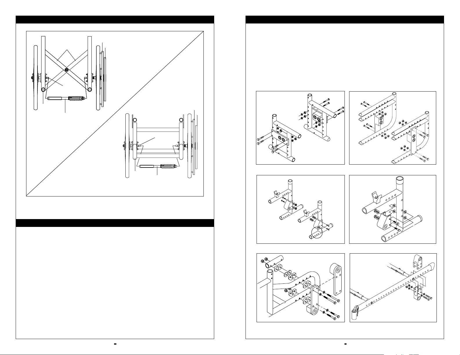
V. ADJUSTMENTS V. ADJUSTMENTS
A. REAR AXLES - CENTER OF
BALANCE
1. Notes
a. The position of the rider’s weight relative
to where you set the rear axles
determines the center of balance.
These are the most important
adjustments on your chair.
b. You can adjust the center of balance by
moving the rear axles forward or back in
the axle plate. On the Zippie GS and the
Quickie IRIS, the axle plate itself moves
forward or back on the side frame to
adjust the center of balance (Fig 11b).
2. Reasons to Adjust
a. Moving the rear axles FORWARD in the
axle plate will lighten the force needed
to turn the chair.
b. Moving the rear axles BACK in the axle
plate makes the chair more stable.
c. Moving the Zippie GS or the Quickie IRIS
axle plate forward lightens the force necessary for turning, while moving it back
stabilizes the chair.
Consult your doctor, nurse or therapist to
find the best rear axle setup for your chair.
Do not change the setup UNLESS you are
sure you are not at risk to tip over.
3. Forward or Rearward Axle Adjustment
(Figs. 11, 11a & 11b)
The center of gravity is adjusted by moving
the rear axle forward or backward to the
additional bearing position (preset with bearings at the factory). For additional
forward adjustments, the axle plate may be
moved forward by inverting the axle plate
and thus giving two additional positions.
Fig. 11 Quickie & Zippie 2
Fig. 11a Quickie & Zippie 2
Fig. 11b Zippie GS
Always adjust rear wheel locks after you
make any change to the axle position.
Make sure lock arms embed in tires at least
1/8 inch when locked. If you fail to do so,
the locks may not keep the rear wheels
from rolling. Refer to User Instruction
Manual for directions.
B. REAR AXLES - SEAT HEIGHT
1. Seat Height - Quickie 2 and
Zippie 2 Only (Fig. 12)
Seat height can be adjusted by moving the
axle plate vertically in the predrilled frame
holes. This allows a 2 1/2” seat height
adjustment. Refer to User Instruction
Manual for directions.
2. Seat Height - Zippie GS Only
(Fig. 12a)
On the Zippie GS, adjust seat height by
moving the rear axle sleeve up or down
in the axle plate. 1.25" adjustment possible
(Fig 12a).
NOTE: Only 20", 22" and 24" wheels available with
one-arm drive.
If you raise the seat too high, you may “outadjust” the caster forks. If this occurs, the
seat will tilt toward the front, and may
cause the rider to fall. To avoid this, you
will need to use a longer caster fork or
fork stem. Refer to User Instruction
Manual for directions.
3. Seat Height - Breezy Series Only
(Fig. 13)
Seat height can be adjusted by inverting the
axle block. This allows a 1” seat
height adjustment.
Fig. 13 Breezy
Fig. 12
Fig. 12a
Fig. 11c
Page 6

930331 Rev. F
11
930331 Rev. F
10
V. ADJUSTMENTS V. ADJUSTMENTS
4. Quickie TS (Fig. 14)
Quickie IRIS (Fig. 15)
a. The center of gravity is adjusted by
moving the rear axle forward or backward to the additional holes located
along the frame.
b. Rotating the entire axle brackets allows
the user to use different wheel sizes
and often different seat heights.
C. REMOVAL AND INSTALLATION
OF DRIVE SHAFT ASSEMBLY
1. Installation (Fig. 16 & 16a)
a. Compress, twist and lock the drive shaft
assembly.
b. Insert one end of the drive shaft assem-
bly into one of the axle tabs.
c. Unlock the drive shaft assembly and
insert it into the opposite axle tab.
2. Removal
a. Compress, twist and lock the drive shaft
assembly.
b. Remove one end of the drive shaft
assembly from one of the axle tabs.
c. Remove the drive shaft assembly from
the opposite axle tab.
d. Unlock the drive shaft assembly and
store it in the drive shaft mounting
brackets.
D. STORAGE OF DRIVE SHAFT
ASSEMBLY
a. Drive shaft mounting (storage) brackets
are mounted on the lower front frame
and lower rear frame or on opposite
ends of a crossbrace.
NOTE: On Zippie GS, drive shaft assembly may be
stored on lower frame only.
b. The drive shaft assembly may be placed
in these brackets and stored
for easy access.
E. REVERSING ONE-ARM DRIVE
MOUNTING SIDES
a The one-arm drive may be mounted on
either side of the chair.
b Follow one-arm drive assembly instruc-
tions in reverse order to disassemble.
c. To remount on opposite side follow
one-arm drive assembly instructions.
F. USE OF ONE-ARM DRIVE
Keep hand clear of center of the wheel or
spokes when propelling the one-arm drive.
This may cause a pinch or crush-type injury.
1. One-Arm Drive Operation
a. To propel both wheels forward, push
both the outer and inner handrim on
the side the one arm drive is mounted.
b. If the outer handrim is mounted on the
right, push the outer handrim to turn
the chair to the right. (Reverse this
instruction if the outer handrim is
mounted on the left.)
c. If the outer handrim is on the right, push
the inner handrim only to turn the chair
to the left. (Reverse this instruction if the
outer handrim is mounted on the right.)
Fig. 16
Fig. 16a (Quickie TS)
Fig. 14
Fig. 15
a
b
Page 7

Sunrise Medical, Inc.
7477 East Dry Creek Parkway • Longmont, Colorado • 80503 USA
(303) 218-4500 or (800) 333-4000
in Canada (800) 263-3390
©2003, Sunrise Medical 7.03
930331 Rev. F
 Loading...