

Page 1

No. 7, Road 12, Industrial Zone, Taichung City 407, Taiwan
Tel: 886-4-2359-1190 [email protected]
Fax: 886-4-2359-3409
www.sunriseiw.com.tw
SUNRISE
HYDRAULIC PUNCHING MACHINE
PM MODELS
OPERATION &
MAINTENANCE MANUAL
Original Instructions
632EG043
12-2012
Page 2

No. 7, Road 12, Industrial Zone, Taichung City 407, Taiwan
Tel: 886-4-2359-1190 [email protected]
Fax: 886-4-2359-3409
www.sunriseiw.com.tw
TABLE OF CONTENTS
Introduction ……………………………………………….…… 1
Safety Precautions ……………………………………………… 2
Transport …………………………………………..…………… 6
Installation ………………………………………………………7
Standard Equipment ………………………………..……….… 9
Control Switches………...…………………………………….… 10
Low pressure tool alignment with JOG mode……...………….… 12
Foot Switch …………………………………………………… 13
Stroke Adjustment …………………………………..………… 14
Adjust the Punch Cylinder Ram ……………………………… 15
Punching Station …………………………………….………… 16
Standard Equipment ……………………………………… 16
Alignment of Punch and Die ………………..…………… 16
Punch and Die Clearance ………………..……………… 17
Adjusting Stripper ………………………….…………… 17
Actual Punching Force ………………………..………… 18
Precaution ……………………………………….……… 18
Punch and Die Lubricant ………………………….…… 18
Punch Operation ……………………......…………….… 19
Punching Station Assembly ……………………………. 21
Optional Tooling
I. Press Brake ……………………….…….……..…… 22
II. Duplicating Table …………………..……………… 23
III. Hydraulic Punching Stripper ………….…………… 25
Maintenance …………………………………………………… 26
Trouble Shooting ………………………………..…….……… 28
Hydraulic Circuit Diagram PM-35 ………………..…………… 30
Hydraulic Parts PM-35 ……………………………………….… 31
Hydraulic Circuit Diagram PM-55, PM-80 …………..……….. 32
Hydraulic Parts PM-55, PM-80 ………………………………… 33
Hydraulic Circuit Diagram PM-120, PM-160, PM-200 ……..… 34
Hydraulic Parts PM-120, PM-160, PM-200………………….…. 35
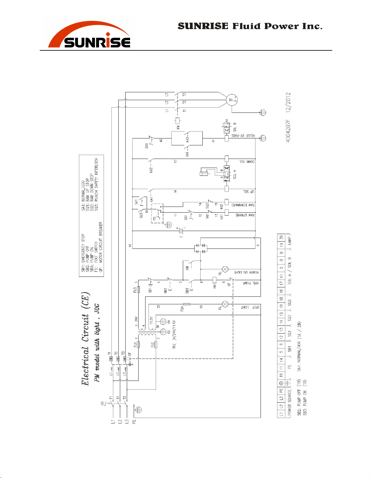
Electrical Circuit Diagram ………………………………….… 36
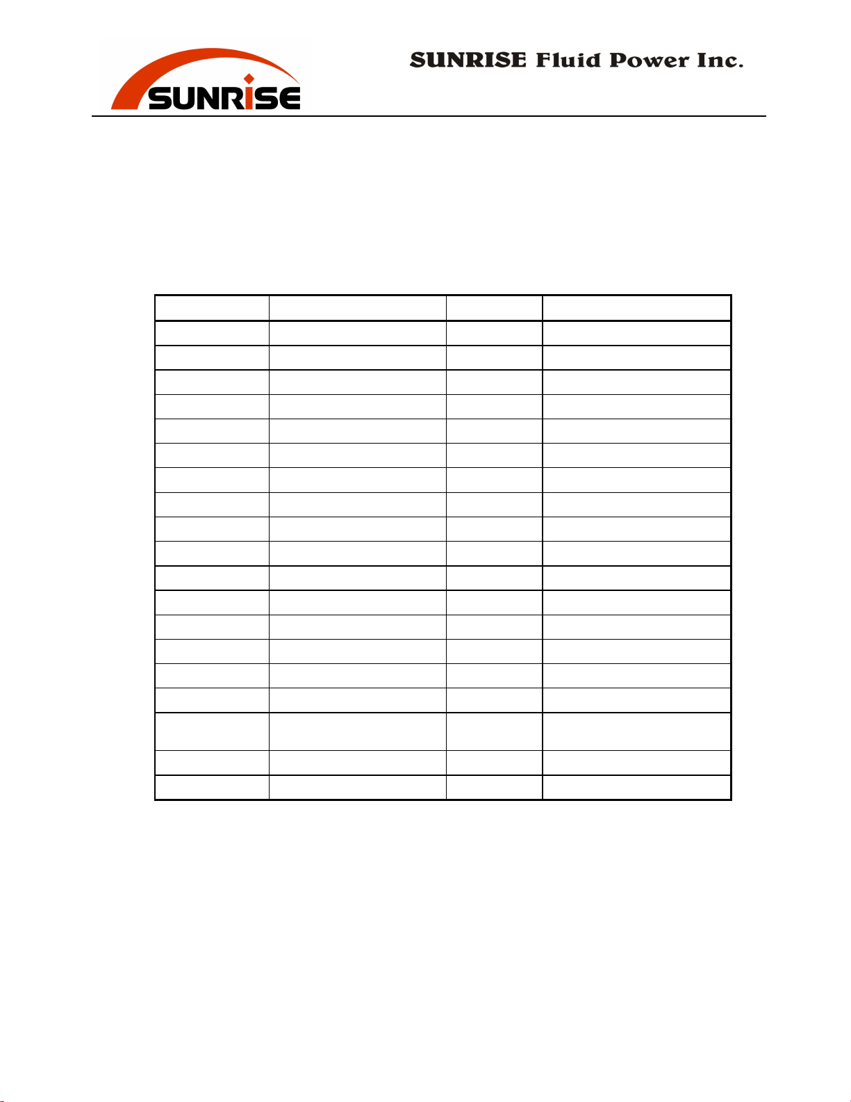
Electrical Parts List …………………………………………… 37
i
Page 3

No. 7, Road 12, Industrial Zone, Taichung City 407, Taiwan
Tel: 886-4-2359-1190 [email protected]
Fax: 886-4-2359-3409
www.sunriseiw.com.tw
INTRODUCTION
The Sunrise Punching Machine is a hydraulically powered machine for
punching holes on metals. There are many optional accessories that can be
used on the punching machine and turns it into an universal machine. Some
example of optional tooling include Press Brake, Bar Shear Tooling, Flat
Bar Shear Tooling, Channel or Sectional Bar Shear Tooling, Angle Shear
Tooling, Notching Tooling, Pipe Notching, Pipe Punching, and punches
and dies of various shapes and sizes.
Each machine has been individually tested in the factory and under-gone an
extensive pre-delivery check to ensure that the machines meet the highest
quality standard. The punching machine has been designed to be a reliable
and dependable machine with excellent performance. We know the
working quality of the machine will confirm that you have made a good
choice by selecting Sunrise products for your facility.
In order to have a better understanding of the operating procedures, to
obtain maximum benefits from the machine, and to minimize the
maintenance cost of the equipment, please have the operators and engineers
read this Manual thoroughly and carefully before operating the machine.
- 1 -
Page 4

No. 7, Road 12, Industrial Zone, Taichung City 407, Taiwan
Tel: 886-4-2359-1190 [email protected]
Fax: 886-4-2359-3409
www.sunriseiw.com.tw
SAFETY PRECAUTIONS
IMPORTANT:
It is the duty of both employer and employees to acquaint themselves
with the safe working practices contained in this manual and ensure
that all operators adopt these practices.
To ensure safe operation, guards are provided for the work stations.
NEVER REMOVE THESE GUARDS. If any guards are damaged or
worn out, replace immediately with new guards.
While every effort has been made to furnish sufficient safe guards, this
equipment, if not operated and maintained properly, has the potential to
cause serious injury or death. A thorough knowledge of the machine and
operating with carefulness is the best protection against accidents.
All operations are controlled by the foot switch. The operator should be
familiar with the control and function of the switch before perform the
operation.
Many warning labels are fixed on the machine. NEVER REMOVE
THESE LABELS. Be sure to follow these warnings to avoid injury.
Please also pay attention to the following general rules:
1. Do not operate the machine unless the stripper is in place. Use of
optional attachments/tooling should also have proper hold-downs and
guards installed.
2.
All operators must wear Protective Glasses during operation ot
protect the eyes.
3. Before each operation, make sure no other person is near the machine.
Only the operator should be near the machine during operation.
- 2 -
Page 5

No. 7, Road 12, Industrial Zone, Taichung City 407, Taiwan
Tel: 886-4-2359-1190 [email protected]
Fax: 886-4-2359-3409
www.sunriseiw.com.tw
4. Any maintenance/repair of electrical/hydraulic circuit; change/adjust of
tooling; and alignment of punch-die should be done only by qualified
engineers or personnel.
5. Always turn off power and disconnect electric supply before doing any
tool change or maintenance work.
6. After tool changes, always check punch & die alignment before
operation.
7. Keep hands clear of all moving parts at all times. Fingers must
not go under or inside the stripper.
8. If any problem or abnormal condition arises during operation, stop
the machine immediately and report to a supervisor. Do not turn on
the machine again until the problem is rectified by qualified personnel.
9. The machine should never be left under power when not in operation
or unattended. Always isolate the machine after turned the power off.
10. After completion of operation, all slugs and waste materials must be
cleaned away from the machine.
11. Regularly check all stations and tooling for defects and wear to
ensure safety and maintain good condition.
12. Heavy materials should be supported.
13. Use handling equipment when lifting heavy tooling and materials.
14. Do not punch partial holes as this creates a side load force on the
punch and can result in tool breakage. Special tooling may be
available for this purpose.
15. Do not punch material thicker than the diameter of the punch.
Doing so can overload and break the punch and create a hazard.
- 3 -
Page 6

No. 7, Road 12, Industrial Zone, Taichung City 407, Taiwan
Tel: 886-4-2359-1190 [email protected]
Fax: 886-4-2359-3409
www.sunriseiw.com.tw
16. Never exceed the rated capacity of the machine. Refer to the
specification chart for details for each model.
The manufacturer shall not be held for any liability for damages, body
injuries and other consequences to machine, material, and/or persons
caused by the non-compliance of the above safety precaution
procedures, in particular for the following situation:
1. Removing or disabling any guards or hold-downs is a violation and
will result in the termination of your warranty.
2. Place of any body part under or inside the safety guards/stripper.
3. Did not wear protective glasses for the eyes.
4. Did not close the stripper during operation.
5. Did not properly adjusted the clearance resulting the tooling
hitting each other.
6. Did not interrupt the main electric power supply before any
maintenance or repair work.
7. Damage of electric parts or risk of fire due to incorrect electric
power supply.
8.
Damage of pump or other hydraulic parts due to incorrect setting
of the limit switches.
- 4 -
Page 7

No. 7, Road 12, Industrial Zone, Taichung City 407, Taiwan
Tel: 886-4-2359-1190 [email protected]
Fax: 886-4-2359-3409
www.sunriseiw.com.tw
DANGER
KEEP HANDS CLEAR OF ALL MOVING PARTS.
ALL GUARDS MUST BE IN POSITION BEFORE OPERATING
THE MACHINE.
ALWAYS POSITION MATERIAL UNDER A CORRECTLY
SET STRIPPER/HOLD-DOWN. NEVER ALLOW THE
MATERIAL TO FEED BEYOND THE HOLD-DOWN.
CAUTION
THOROUGHLY READ THE OPERATION MANUAL BEFORE
OPERATION.
TURN OFF POWER AND ISOLATE THE MACHINE WHEN
CHANGING TOOLING OR DOING MAINTENANCE.
ALL MAINTENANCE/REPAIR WORK MUST BE DONE BY
QUALIFIED PERSONNEL.
IF ANY PROBLEM OR ABNORMAL CONDITION OCCURS,
STOP THE MACHINE IMMEDIATELY. DO NOT OPERATE
THE MACHINE AGAIN UNTIL THE PROBLEM IS FIXED.
- 5 -
Page 8
No. 7, Road 12, Industrial Zone, Taichung City 407, Taiwan
Tel: 886-4-2359-1190 [email protected]
Fax: 886-4-2359-3409
www.sunriseiw.com.tw
TRANSPORT
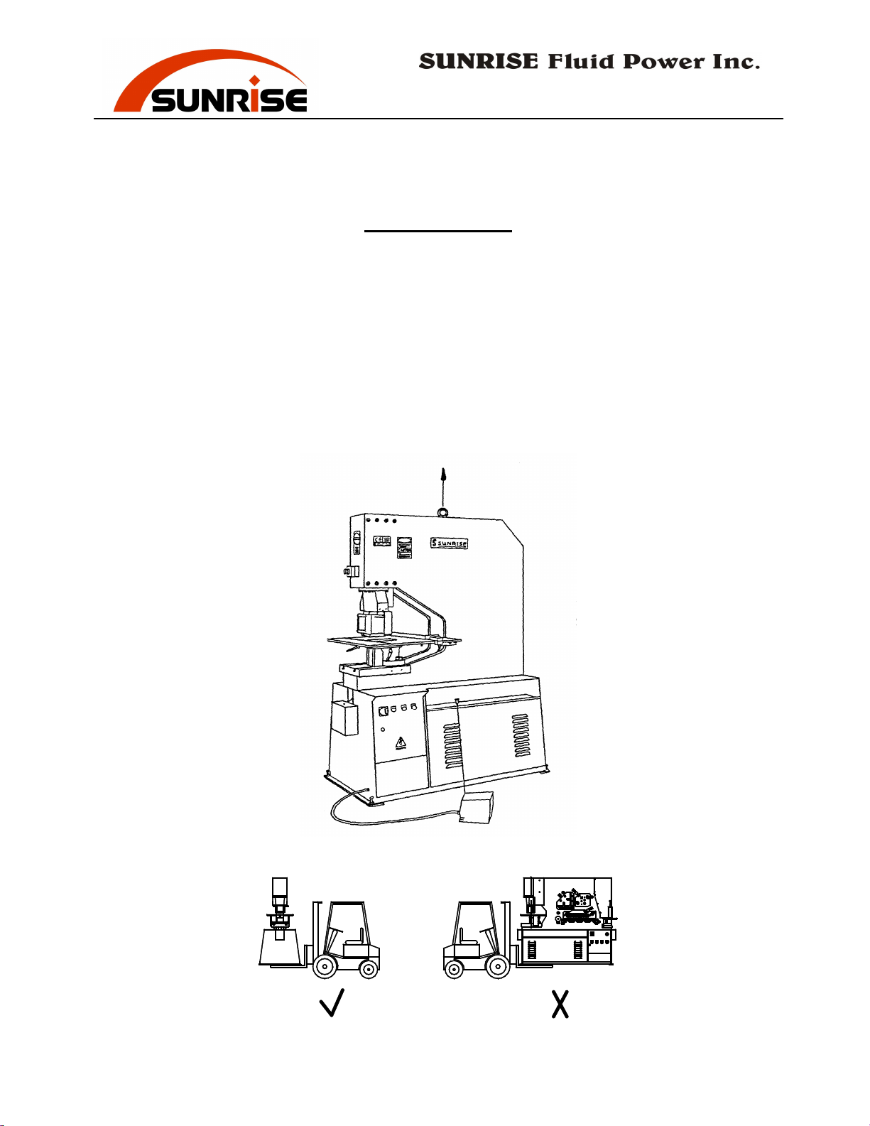
When transporting the machine by a crane, hook the crane to the eye bolt
on top of the machine.
Do not use slings under the machine.
care if lifting / transporting the machine with forklifts. The forks should
extend fully to cover the width of the machine.
either end
.
Do not put the forks from
NOTE:
As the top of the machine is heavy, the high center of gravity can
cause the machine to tip over if machine is not in good balance.
Pay special
- 6 -
Page 9

No. 7, Road 12, Industrial Zone, Taichung City 407, Taiwan
Tel: 886-4-2359-1190 [email protected]
Fax: 886-4-2359-3409
www.sunriseiw.com.tw
INSTALLATION
The machine only requires the normal industrial concrete foundation. If the
ground is uneven and the machine vibrates during operation, use foundation
bolts to tighten the machine firmly to the ground or alternatively mount the
machine on anti-vibration pads.
IMPORTANT:
Maintain a spacious working area around the machine for safety.
Have the work area well illuminated with proper lighting.
Clean the scraps and waste materials regularly, and make sure the work
area is free of obstructing objects.
Keep the ground free of oil and make sure it is not slippery.
If long lengths of material are to be fed into the machine, make sure
that they will not extend into any gangways.
Crowded, poorly illuminated or slippery area are often causes for
accidents.
Remove all anti-corrosion grease after installing the machine. Check that
the oil reservoir, located in the machine base, has been properly filled.
When refilling oil, use recommended oil and fill the reservoir to the upper
level of the oil level gauge.
Connecting Power Supply
Electrical wiring must be done by a qualified electrician. Before
connecting the electrical supply, make sure the voltage and current is
compatible to the electrical components in the machine. Check the data
shown in the electrical control box.
IMPORTANT: Turn off Supply Electricity at your facility's circuit
breaker before making electrical connections to the machine.
- 7 -
Page 10
No. 7, Road 12, Industrial Zone, Taichung City 407, Taiwan
Tel: 886-4-2359-1190 [email protected]
Fax: 886-4-2359-3409
www.sunriseiw.com.tw
To connect the power cord:
1) Open the electric box.
2) Remove the small panel under the electric box.
3) Insert the power cord through the entrance hole on the base of machine,
and then through the base of electric box.
4) Connect the three phase wires to the power terminal strip in the
electric box.
5) Also make sure to ground the machine properly.
6) Check that the power cord surface is not damaged, scratched or cut
during installation.
7) Reinstall the panel and close the electric box.
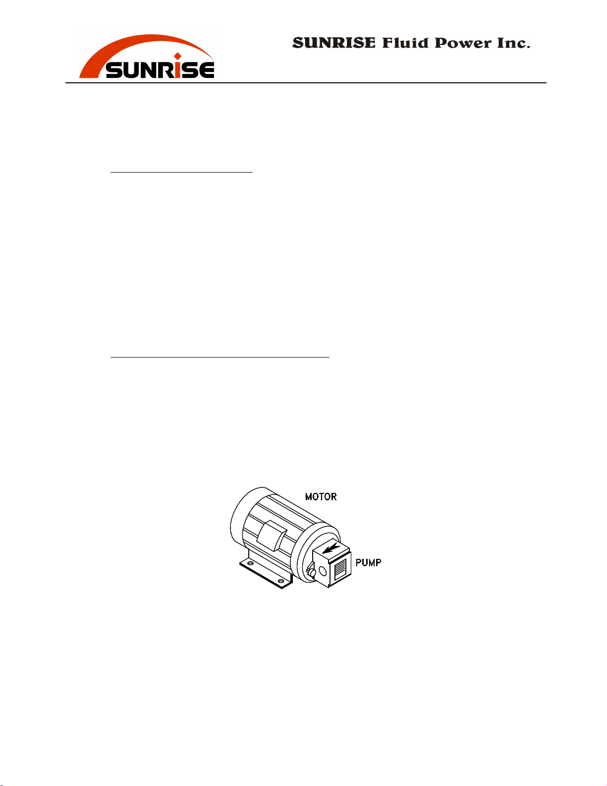
To check the correct rotation of the motor.
Remove the back cover.
Briefly start and stop the motor and check that the motor rotates in the
same direction as the arrow indicated on motor.
can severely damage the pump.
To change the motor rotation, first make sure the power is disconnected,
Improper rotation
then reverse any two of the three phases of the electrical power supply.
- 8 -
Page 11

No. 7, Road 12, Industrial Zone, Taichung City 407, Taiwan
Tel: 886-4-2359-1190 [email protected]
Fax: 886-4-2359-3409
www.sunriseiw.com.tw
STANDARD EQUIPMENT SUPPLIED WITH MACHINE
(including items pre-installed on the machine)
Punch and Die (20mm) 1 set
Punch Support Tables 1 set
Punch Retaining Nut / Sleeve 1 set
Die Holder 1 pc
Punch Stripper Unit 1 pc
Lifting Eye Bolt 1 pc
TOOL BOX 1 pc
Adjustable Spanner (250mm) 1 pc
Screw Drivers (+) 1 pc
Screw Driver (-) 1 pc
Hex Key Wrench Set 1 set
Hex Wrench (12mm) 1 pc
Hex Wrench (14mm) 1 pc
SPA Spanner 1 pc
- 9 -
Page 12

No. 7, Road 12, Industrial Zone, Taichung City 407, Taiwan
Tel: 886-4-2359-1190 [email protected]
Fax: 886-4-2359-3409
www.sunriseiw.com.tw
CONTROL SWITCHES
EMERGENCY STOPS
the machine in an emergency. The Emergency button must be released
before the PUMP ON button will function. To release the emergency stop
button, turn knob slightly to the right.
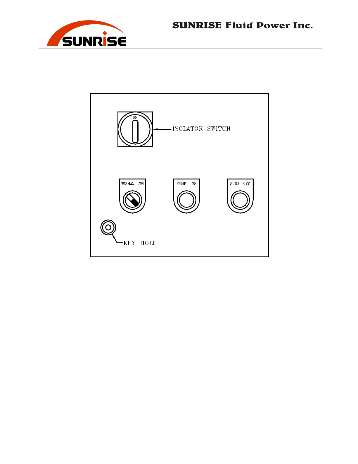
ISOLATOR Switch
also functions as a lock for the electric box. At the ON position the switch
locks the electric box and enables you to start the machine. At the OFF
position, the power is cut off and the electric box can be opened.
PUMP ON
- Push this button to turn on the machine. All EMERGENCY
STOP buttons must be released before the PUMP ON button will function.
The green POWER LIGHT stays on when the machine is turned on.
PUMP OFF
- Push this button to turn off the machine.
NORMAL/JOG keyed Switch
normal (automatic return) mode and the jog (low pressure, slow speed,
non- return) mode. Use the normal mode to operate the machine. Use the
jog mode to align punch/die, to set blade clearance, and to set the strokes.
In NORMAL mode, the ram/slide move in both up and down directions. In
JOG mode, the hydraulic system is in low pressure setting and the
ram/slide move only in downward direction at slower speed. Also refer to
the section on Low Pressure Tool Alignment in JOG mode.
– Use the EMERGENCY STOP buttons to stop
- This switch controls the main electric source. It
- This switch allows selection between the
- 10 -
Page 13
No. 7, Road 12, Industrial Zone, Taichung City 407, Taiwan
Tel: 886-4-2359-1190 [email protected]
Fax: 886-4-2359-3409
www.sunriseiw.com.tw
- 11 -
Page 14

No. 7, Road 12, Industrial Zone, Taichung City 407, Taiwan
Tel: 886-4-2359-1190 [email protected]
Fax: 886-4-2359-3409
www.sunriseiw.com.tw
Low pressure tool alignment with JOG mode
Sunrise Fluid Power Inc. is the market leader in providing low pressure tool
alignment setting on its products. When the NORMAL/JOG switch is
turned to JOG mode, the machine provides a low pressure and low speed
setting for safer tool alignment operation. This will reduce tool damages
due to miss-alignment of tools and increase the operator safety. If a
material is placed under the punch in JOG mode, the punch will only make
a dent on the material without punching through. In addition, the punch
cylinder will only move downward when the foot paddle is pressed, and
will not retract backup when the foot paddle is released. Turn the
NORMAL/JOG switch to NORMAL to move the cylinder upward.
WARNING: for ease of tool alignment, the stripper cover is allowed to
open in JOG mode. Even with the low pressure setting, be sure to
keep all body parts away from moving parts, wear appropriate eye
protection goggles and gloves for eye and hand protection. The JOG
mode is a keyed switch, and only properly trained and authorized
personnel should have access to the key and use the machine with JOG
mode.
- 12 -
Page 15
No. 7, Road 12, Industrial Zone, Taichung City 407, Taiwan
Tel: 886-4-2359-1190 [email protected]
Fax: 886-4-2359-3409
www.sunriseiw.com.tw
FOOT SWITCH
The machine uses a foot switch for easy and fast operation control. The
foot switch enables the operator to use the machine while holding the work
piece with both hands. NEVER has one operator hold the material and
another operator press the foot switch.
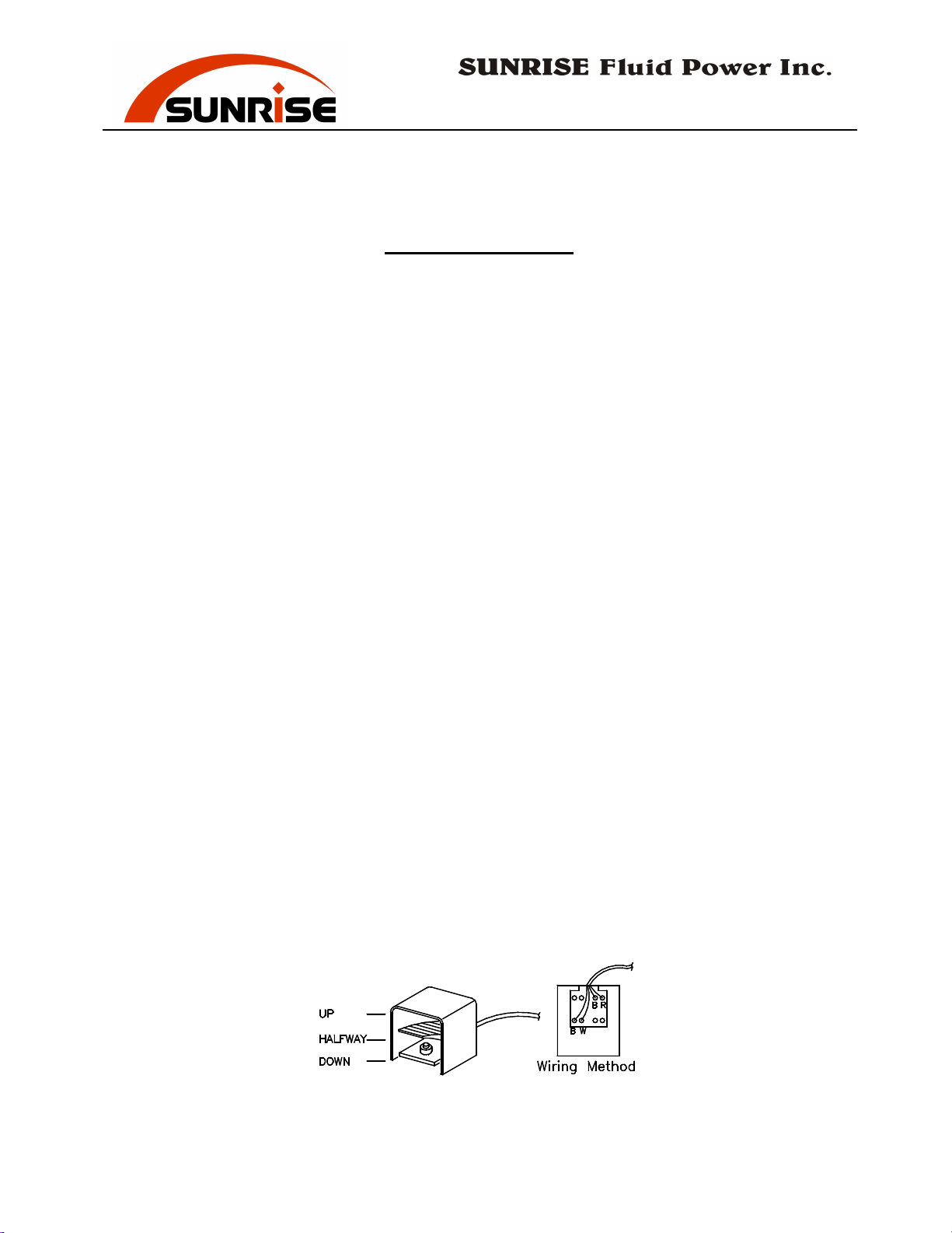
The foot switch has three positions: UP, HALFWAY and DOWN.
UP position is when you release the foot switch completely.
HALFWAY position is when you press or release the foot switch halfway.
DOWN position is when you press the foot switch all the way down.
When not pressed, an internal spring pushes the switch to the UP position.
The foot switch functions differently in the NORMAL and the JOG modes.
In NORMAL mode
downward motion of the slide. Release the foot switch to HALFWAY
position will cause the slide to stop. This is very useful in position the
work piece without using the gauge stoppers. Press the foot switch again
to Down position and the slide will continue moving downward until
reaching the lowest position set by the limit switches. Releasing the foot
switch completely (UP position) will cause the slide to return to its up
position.
In JOG mode
, press the foot switch to the DOWN position for the
downward motion of the slide. The slide stops moving when the foot
switch is released to either HALFWAY position or UP position. The slide
does not move back up even when foot switch is completely released. This
allows the operator to make necessary adjustment / alignment. In other
words, the slide moves only in one direction in JOG mode. To move the
slide back to the up position, switch the Normal/Jog switch to NORMAL.
, press the foot switch to DOWN position for the
- 13 -
Page 16
No. 7, Road 12, Industrial Zone, Taichung City 407, Taiwan
Tel: 886-4-2359-1190 [email protected]
Fax: 886-4-2359-3409
www.sunriseiw.com.tw
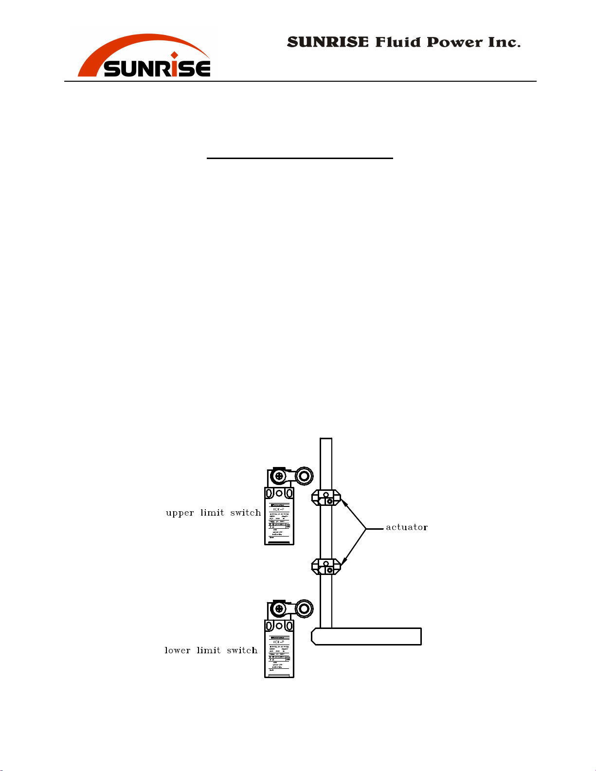
STROKE ADJUSTMENT
Certain working operations do not require a full working stroke. For large
quantities of the same operation, merely execute the required working
stroke distance to save operating time. The position and length of the
cylinder strokes are controlled by limit switches and actuators on a drive
bar installed inside the back panel of machine. There are two limit
switches, one for the upper limit and one for the lower limit. Adjust the
length of stroke by shifting the position of the actuator mount on the drive
bar. See Figure.
IMPORTANT:
reaches the full extend or full extract position. In other words, the pump
should be unloaded in upper or lower limit of the slide travel. Fail to do so
can overload the motor and damaging the pump. If the pump is not in
unloading position at either upper or lower limit, a loud noise is heard from
the pump. Immediately turn the machine off and adjust the limit switch
actuators to set the proper stroke movement.
The limit switch must be actuated before the Cylinder
- 14 -
Page 17

No. 7, Road 12, Industrial Zone, Taichung City 407, Taiwan
Tel: 886-4-2359-1190 [email protected]
Fax: 886-4-2359-3409
www.sunriseiw.com.tw
ADJUST THE PUNCH CYLINDER RAM
The alignment of the punch cylinder ram is guided by a "bronze guide pad"
inside the cylinder cast. When the ram is loose and starts to swivel or
when the ram is misaligned (not square with the die base), the punch ram
should be adjusted.
To adjust the punch ram, follow these steps:
1) Remove the two locking nuts located on the left side of the cylinder
cast.
2) Adjust the two adjusting screws to lightly press the guide pad onto the
ram.
3) Check the adjustment by moving the ram up and down with non-round
(oblong or square) punches and dies. The ram should be moving
smoothly and without any gaps.
4) Retighten the lock nuts to prevent loosening.
- 15 -
Page 18

No. 7, Road 12, Industrial Zone, Taichung City 407, Taiwan
Tel: 886-4-2359-1190 [email protected]
Fax: 886-4-2359-3409
www.sunriseiw.com.tw
PUNCHING STATION
Standard Equipment
The machine is equipped with one set of Ø20mm round punch and die.
Many other punching tools of different sizes are also available upon request.
In addition, a large 2-piece support table with gauges is installed as
standard equipment. Measuring scales on the table enable accurate
positioning.
IMPORTANT:
operation. On some models with an interlock limit switch inside the
stripper back cover, the punching station is IMMOBILIZED if the stripper
is open.
Alignment of Punch and Die
The punch and the die may have previously been centered. However, you
should check the tools regularly for proper alignment. To center the die,
follow these steps:
1) Insert Punch into Retaining Nut, then tighten the nut onto the Retaining
Thread.
2) Insert the Die into the Holder and secure the set screw.
3) Loosen all of the die holder fixing bolts
4) Lower the punch gradually (by using the JOG mode).
WARNING: Be very careful that the punch does not hit the die
which can break the punch and create a hazard.
5) After the punch is inside the die, turn power off and isolate the machine.
6) Adjust the position of the Die Holder until the Clearance around the
punch and die is even all the way around.
7) Tighten the die holder bolts to fix the die position.
8) Adjust the limit switches to change the stroke length if necessary.
When setting up square or oblong punches and dies, be sure to properly
locate the key on top of the punch in the keyway of the punch retaining
thread. Check carefully the alignment (both position and direction) of the
die with the punch. Incorrect set up will damage the punch and die, and
may cause danger.
The punch stripper must be closed properly during
- 16 -
Page 19
No. 7, Road 12, Industrial Zone, Taichung City 407, Taiwan
Tel: 886-4-2359-1190 [email protected]
Fax: 886-4-2359-3409
www.sunriseiw.com.tw
IMPORTANT:
Be sure to check the alignment of the punch and die
whenever tools are changed.
Punch and Die Clearance
Punch size is the same as the desired hole size. Die size is bigger by the
clearance. The clearance depends on the thickness of the material. The
clearance is usually about 10% of the material thickness. Please also refer
to the following chart for recommend clearance.
Material Thickness mm up to 4 4 - 9 9 – 14 14 - 20
Die Clearance mm
0.2 0.7 1.2 1.7
Adjusting Stripper
The distance between the stripper and the material should be adjusted
to about 2~3mm. Adjust the stripper height each time when changing
to material of different thickness.
Adjust the stripper height by turning the large knurled screws at both
sides of the stripper.
If the stripper tend to fall down at the right side, tighten the spring at
the left side of stripper.
Make sure the stripper is at even height for left and right sides. The
stripper should be adjusted so that the work-piece contact the stripper
evenly when the punch retracts out of the material. Unbalanced
stripping may break the punch and cause hazard.
If the material cannot have adequate contact with the stripper when
stripping, such as asymmetrical material, material too small, or punched
hole too close to the edge of material, do not proceed with the punching
operation.
The stripper has exchangeable plates with various opening sizes to match
the size of the hole. Select the plate with the smallest suitable opening.
Keeping the opening close to the size of punch will greatly reduce
deformation, especially on thinner materials.
- 17 -
Page 20

No. 7, Road 12, Industrial Zone, Taichung City 407, Taiwan
Tel: 886-4-2359-1190 [email protected]
Fax: 886-4-2359-3409
www.sunriseiw.com.tw
Actual Punching Force
The actual force required in a punching operation is calculated by the
circumference of the hole multiplied by the thickness of material multiplied
by tensile strength of material.
Max. Capacity = circumference x thickness x tensile strength
The capacity chart is based on material with 45 kg/mm2 tensile. Do not
attempt a punching operation that requires force over the maximum
capacity of the machine.
Precaution
1) Always use die with the proper clearance.
2) Always check the alignment after each tool change.
3) To prevent overloading and breakage of the punch, do not punch
material which is thicker than the hole diameter,
4) Do not punch partial holes. Punching incomplete holes will cause the
punch and die to bend and break.
5) Applying some lubricant oil on the punch will prolong the life of the
punch and reduce the stripping load.
6) Regrinding of punching tools is not recommended.
Punch and Die Lubricant
SHELL - GARIA 927
B. P. - SERVORA 68
CASTROL - ILOBROACH 219
DUCKHAMS - ADFORNOL EP7
JOSEPH BATSON - LB 733
- 18 -
Page 21

No. 7, Road 12, Industrial Zone, Taichung City 407, Taiwan
Tel: 886-4-2359-1190 [email protected]
Fax: 886-4-2359-3409
www.sunriseiw.com.tw
Punch Operation
Punching on Flat Plates:
1) Check again that the stripper, punch/die alignment are properly
adjusted.
2) Set the gauging stoppers to the desired position.
3) Position the plate on the working table against the stoppers.
4) Press the foot switch to the DOWN position to execute the punch.
5) Release the foot switch for the punch to retract. During stripping,
the material can be lifted up against the stripper and then drop off
when the punch retracts out of the hole.
fingers as the material movement has potential of hazard.
Be very careful with
Punching on Angles:
1) Check again that the stripper, punch/die alignment are properly
adjusted.
2) Remove the front piece of the 2-piece table.
3) Set the gauging stoppers to the desired position.
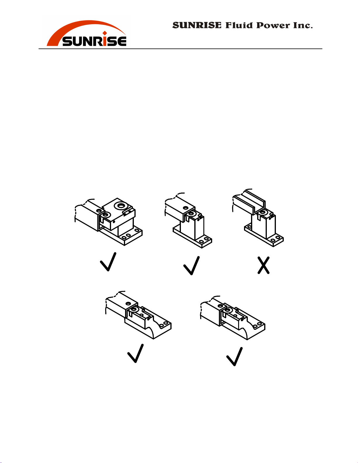
4) Position the angles against the die holder with one flange facing
downward.
upward.
Do not position the angle with one flange facing
See figure.
5) Press the foot switch to the DOWN position to execute the punch.
6) Release the foot switch for the punch to retract. During stripping,
the material can be lifted up against the stripper and then drop off
when the punch retracts out of the hole.
fingers as the material movement has potential of hazard.
Be very careful with
Punching on Channels:
1) If punching the channel web, use the single-hole die holder (optional)
with the table removed. If punching the channel flange, use the
overhang two-hole die holder with the lower support portion and the
front piece of the 2-piece table removed. Special goose-neck die
holder is also available for punching both channel web and channel
flange. See figure.
2) Check again that the stripper, punch/die alignment are properly
adjusted.
3) Set the gauging stoppers to the desired position.
- 19 -
Page 22
No. 7, Road 12, Industrial Zone, Taichung City 407, Taiwan
Tel: 886-4-2359-1190 [email protected]
Fax: 886-4-2359-3409
www.sunriseiw.com.tw
4) If punching channel web, position the channel with both flanges
facing downward. If punching channel flange, position the channel
with the flange being punched on top. See figure.
5) Press the foot switch to the DOWN position to execute the punch.
6) Release the foot switch for the punch to retract. During stripping,
the material can be lifted up against the stripper and then drop off
when the punch retracts out of the hole.
fingers as the material movement has potential of hazard.
Be very careful with
- 20 -
Page 23
No. 7, Road 12, Industrial Zone, Taichung City 407, Taiwan
Tel: 886-4-2359-1190 [email protected]
Fax: 886-4-2359-3409
www.sunriseiw.com.tw
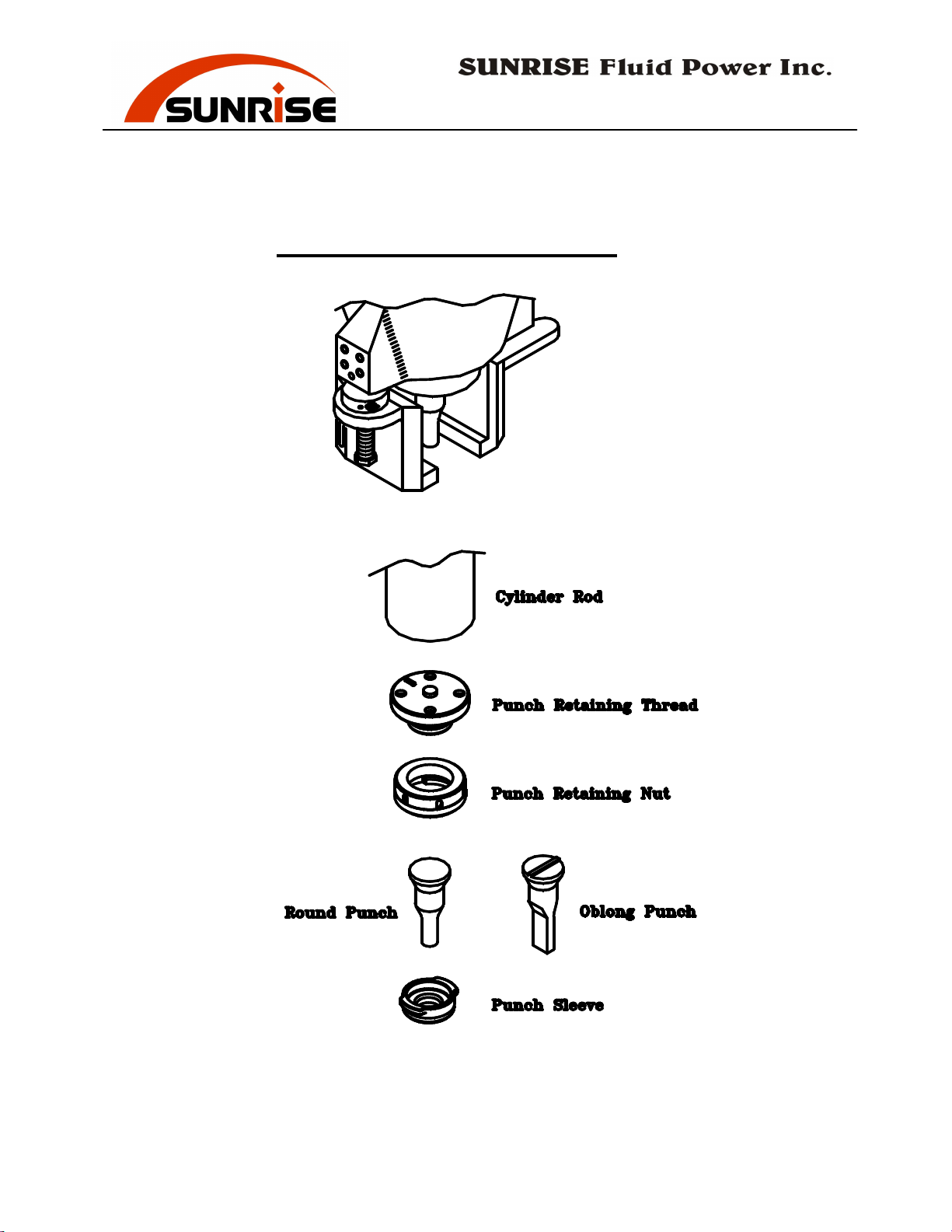
Punching Station Assembly
- 21 -
Page 24

No. 7, Road 12, Industrial Zone, Taichung City 407, Taiwan
Tel: 886-4-2359-1190 [email protected]
Fax: 886-4-2359-3409
www.sunriseiw.com.tw
OPTIONAL TOOLING
I. PRESS BRAKE
Three kinds of press brakes are available to be installed on the Punch
station to perform bending work. The single-vee press brake is for bending
thick materials. The multi-vee press brake is for bending thin materials.
The angle bending tool is for bending angles after a Vee notch operation.
Always bend the material at the center position of the tooling (directly
under the cylinder ram). Do not bend the material at the side of the tool as
that will create side-load force on the tool and cylinder.
WARNING
As the press brake tool is not covered by guards, pay special attention to
safety when using this tool. Always make sure no fingers or other body
parts is in between the upper tool and lower die before excusing the
bending operation.
NOTE:
While using the press brake, the pump is not unloaded by the limit switch
when the upper tool reach the lowest position onto the lower die. At this
position the oil pressure stays at the maximum pressure set by the relief
valve, until the foot paddle is released to allow the cylinder to retract. This
will cause the oil temperature to raise quickly, also may shorten the life of
pump and hydraulic parts due to over-loading. Do not allow the top tool to
stay at the low position too long by release the foot paddle immediately
when bending is complete. The press brake is an optional tooling intended
for occasional operation. Continuous production work is not recommended.
Allow intermit break period for the oil to cool down. Use fan for cooling
down when oil temperature is too high. Lower the pressure setting by
adjust the relief valve to the level just enough capacity to perform the
bending operation.
- 22 -
Page 25

No. 7, Road 12, Industrial Zone, Taichung City 407, Taiwan
Tel: 886-4-2359-1190 [email protected]
Fax: 886-4-2359-3409
www.sunriseiw.com.tw
II. DUPLICATING TABLE
The duplicating table is to copy the position of existing holes on a master
plate to the working plate. This device can greatly save time and labor on
repetitious punching. We strongly recommend the hydraulic stripper to be
used together with the duplicating table.
To duplicate the holes, follow these steps:
1.) Make a master plate and fix it on the extended table. The material
should be placed against the zero point at the left upper corner. Secure
the plate with the screws on two sides.
2.) Fix the working material on the two clamps. The material should be
placed against the zero point at the stopper guide on the right lower
corner.
3.) Move the working material along the X-Y linear guide until the pointing
device is pointed to the hole on the master. Then simply push and hold
the button on the pointing device. Enacted by compress air, the point
device comes down into the hole and locks into position.
4.) Press the foot paddle to punch the hole.
The corn shape tip of the pointing device provides a self-centering effect
for precise positioning. Various sizes of the corn shape tip are provided for
the different master plate thickness and hole sizes. Select the correct tip
that will have full contact around the hole to ensure accurate positioning.
The duplicating table for PM-T models (310mm throat) has approximately
the following dimension (mm):
Main Table (for working material): 850 (W) x 320 (D)
Extended Table (for master): 950 (W) x 560 (D)
Copiable Area: 760 (W) x 270 (D)
The duplicating table for PM-LT models (510mm throat) has approximately
the following dimension (mm):
Main Table (for working material): 850 (W) x 532 (D)
Extended Table (for master): 950 (W) x 760 (D)
Copiable Area: 760 (W) x 470 (D)
- 23 -
Page 26

No. 7, Road 12, Industrial Zone, Taichung City 407, Taiwan
Tel: 886-4-2359-1190 [email protected]
Fax: 886-4-2359-3409
www.sunriseiw.com.tw
The duplicating table for PM-XT models (760mm throat) has
approximately the following dimension (mm):
Main Table (for working material): 850 (W) x 782 (D)
Extended Table (for master): 950 (W) x 980 (D)
Copiable Area: 760 (W) x 720 (D)
- 24 -
Page 27

No. 7, Road 12, Industrial Zone, Taichung City 407, Taiwan
Tel: 886-4-2359-1190 [email protected]
Fax: 886-4-2359-3409
www.sunriseiw.com.tw
III. HYDRAULIC PUNCHING STRIPPER
The hydraulic punching stripper moves down with hydraulic force and
holds the material in position. Therefore, it increases the accuracy of the
punching and reduces deformation. The hydraulic stripper moves
downward before the punching takes place. It moves up after the punching
is completed and the punch is stripped out of the hole. The hydraulic
stripper is highly recommended when using the duplicating table to ensure
the accuracy and performance.
To use the hydraulic stripper, turn the Hydraulic Stripper Auto/Manual
switch on the control panel to AUTO position. Position the material as in
normal punching operation. The hydraulic stripper will function
automatically for each punching operation.
To adjust the height of the stripper, turn the screws in the rod on two sides
of the stripper to move up and move down the position of the stripper. The
stripper height should be adjusted so that when activated it will press the
material firmly and evenly. Make sure to have the same height on both
sides so that the stripping force will be balanced. Unbalanced stripping
may break the punch and cause hazard.
If the material cannot have adequate contact with the stripper, such as
asymmetrical material, material too small, or punched hole too close to the
edge of material, do not proceed with the punching operation.
If the hydraulic stripping is not desired, turn off the hydraulic stripper by
switching the Hydraulic Striper Auto/Manual switch to MANUAL.
Warning:
The hydraulic stripper can break fingers and cause serious injuries. Never
remove the guards around the stripper. Before each punch, always pay
special care that nothing is under the stripper other than the material being
punched.
- 25 -
Page 28

No. 7, Road 12, Industrial Zone, Taichung City 407, Taiwan
Tel: 886-4-2359-1190 [email protected]
Fax: 886-4-2359-3409
www.sunriseiw.com.tw
MAINTENANCE
1.
Before operating the machine
Routinely check the electrical power cable and the foot switch cable
for any loosening or damage.
Inspect the punch, die, and safety guards to ensure they are in good
condition.
Clean all slugs, cut off pieces, and other waste material from each
work stations and around the machine.
2.
Filter and Oil Change
:
The first oil change should be performed after approximately 600
operating hours. Further oil change is needed for every 2000 operating
hours. A drain outlet is located at the base of the oil tank. Do not mix
different brands of oil.
Hydraulic Fluid (or equivalent)
Mobil DTE 46
Esso Nuto H46
Shell Tellus 46 or Hydraulic oil 46
B.P. Energol HLP 46
Castrol Hyspin AWS 46 6018
3.
Oil temperature:
The oil temperature should be under 50 degrees Celsius. If the
upper/lower limit switches are not set correctly for unloading of the
pump, the oil temperature can raise quickly. Adjust the limit switches
so the pump will be in the unloading condition.
4.
Oil level
:
Make sure the hydraulic oil level is in the range indicated on the oil
level gauge. It is better to keep the oil level close to the high mark
indicated on the gauge.
:
- 26 -
Page 29
No. 7, Road 12, Industrial Zone, Taichung City 407, Taiwan
Tel: 886-4-2359-1190 [email protected]
Fax: 886-4-2359-3409
www.sunriseiw.com.tw
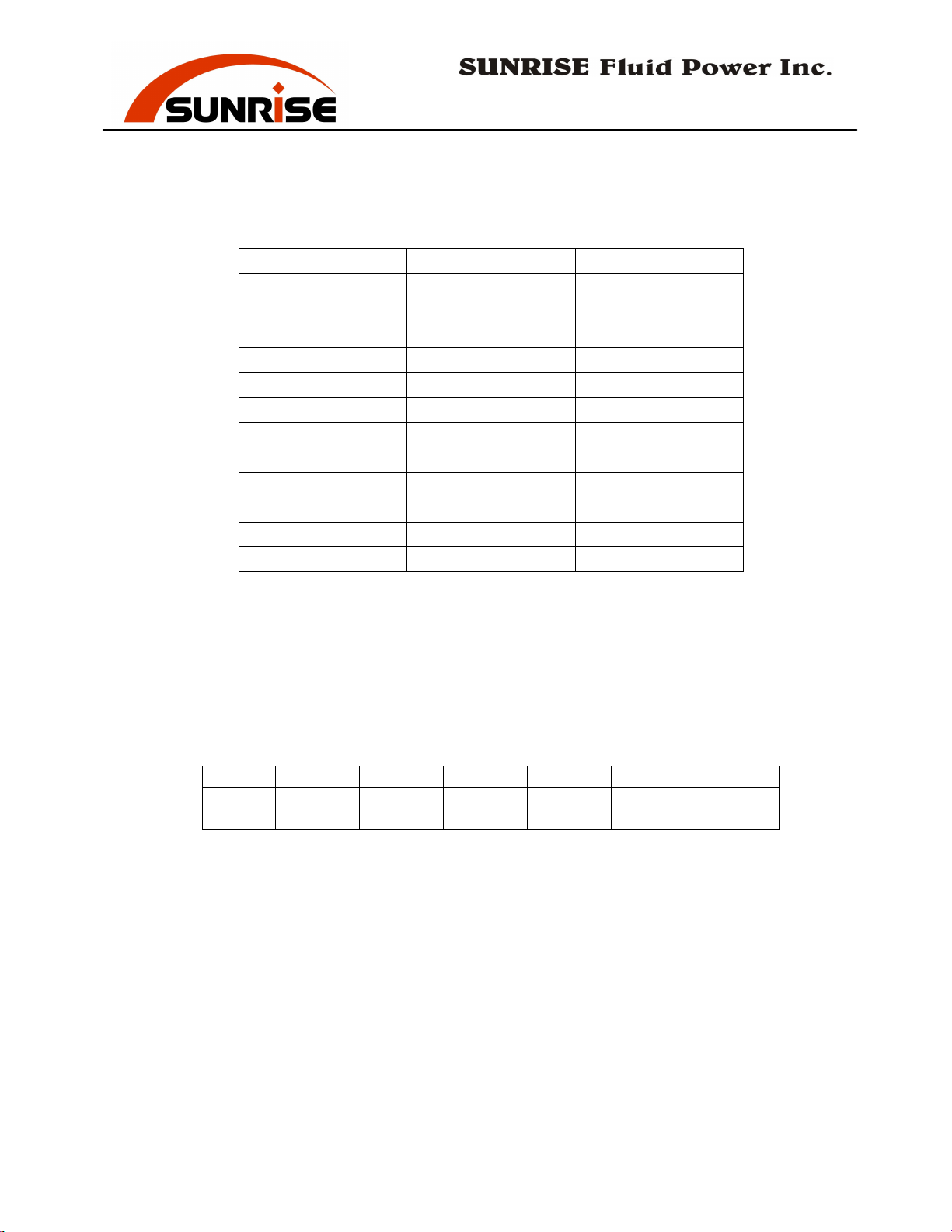
Model Capacity (liter) Oil Required (liter)
PM-35T 91 73
PM-35LT 102 82
PM-35XT 112 88
PM-55T 100 79
PM-55LT 116 89
PM-55XT 123 94
PM-80T 117 92
PM-80LT 128 100
PM-80XT 102 74
PM-120LT/XT 109 94
PM-160LT/XT 131 113
PM-200LT/XT 136 117
5.
Hydraulic pressure
:
The working pressure of the hydraulic system is pre-set in the factory.
The pressure should ONLY be adjusted by the service engineer. There
is a pressure gauge to indicate the working pressure of the machine.
The pressure gauge should be locked and be used only during
service/maintenance work.
Model PM-35 PM-55 PM-80 PM-120 PM-160 PM-200
Max
Pressure
240 kg/cm
2
235 kg/cm
2
230 kg/cm
2
255 kg/cm
2
230 kg/cm
2
230 kg/cm
2
AIRBORNE NOISE
The continuous airborne noise level of the machine under normal condition
is approximately 75 dB 5 dB.
- 27 -
Page 30
No. 7, Road 12, Industrial Zone, Taichung City 407, Taiwan
Check the cable connection
Tel: 886-4-2359-1190 [email protected]
Fax: 886-4-2359-3409
www.sunriseiw.com.tw
TROUBLE SHOOTING
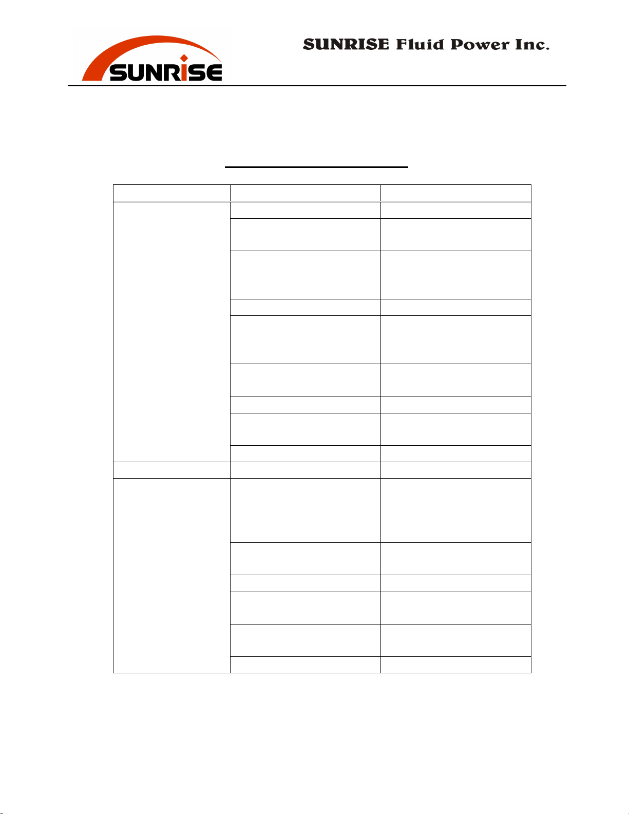
Problem Probable cause Solution
Motor cannot start 1. No power. Check the power source.
2. Isolator switch not turn
on.
3. Emergency buttons not
released.
4. Motor broken. Replace motor.
5. Motor power cable not
connected properly.
6. Motor circuit breaker
jumped to OFF.
7. Fuse broken. Check and replace fuse.
8. Magnetic switch broken
or burn out.
9. Transformer broken. Replace transformer
Motor is on, but
machine won't move
1. Motor turning in wrong
direction.
2. Not enough hydraulic
oil.
3. Solenoid valve stuck. Clean or replace valve.
4. Solenoid valve coil burn
out.
5. Foot paddle not sending
signal.
6. Relay stuck or burn out. Replace relay
Turn the switch to ON
position.
Release both emergency
buttons by turning knob to
the right.
and reconnect cable.
Change cable if worn out.
Reset the breaker to ON
position.
Replace switch
Turn machine off. Change
any two of the three power
source wire. Re-check
motor direction.
Check oil level and add oil
if necessary.
Replace coil.
Check paddle and replace
switch is necessary.
- 28 -
Page 31
No. 7, Road 12, Industrial Zone, Taichung City 407, Taiwan
Tel: 886-4-2359-1190 [email protected]
Fax: 886-4-2359-3409
www.sunriseiw.com.tw
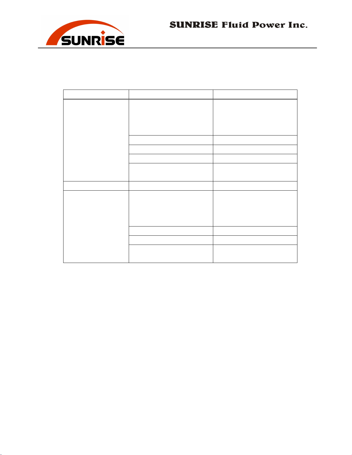
Problem Probable cause Solution
Machine moves, but
cannot reach
capacity
1. Relieve valve not set
correctly
Check hydraulic pressure
and adjust relieve valve
(tighten to increase
pressure)
2. Relieve valve broken. Replace relieve valve.
3. Pump broken. Replace pump.
4. Cylinder internal leak. Contact dealer for service.
5. Pilot check valve not set
correctly.
Adjust the correct pressure
setting of the valve.
Excess hydraulic
noise
1. Motor turning wrong
direction.
Turn machine off. Change
any two of the three power
source wire. Re-check
motor direction.
2. Pump worn out. Replace pump.
3. Filter is dirty. Replace filter element.
4. Not enough oil. Check oil level and add oil
if necessary.
- 29 -
Page 32
No. 7, Road 12, Industrial Zone, Taichung City 407, Taiwan
Tel: 886-4-2359-1190 [email protected]
Fax: 886-4-2359-3409
www.sunriseiw.com.tw
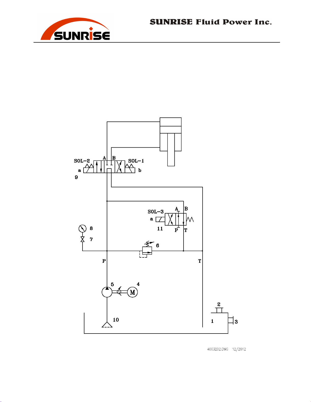
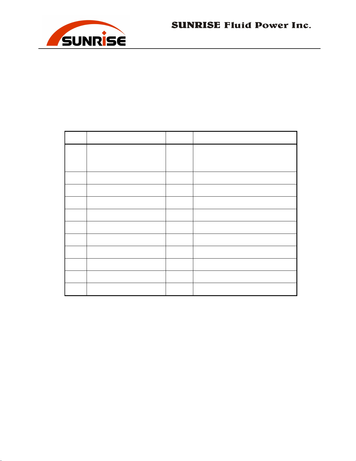
Hydraulic Circuit Parts
PM-35
(with low pressure JOG)
- 30 -
Page 33
No. 7, Road 12, Industrial Zone, Taichung City 407, Taiwan
Tel: 886-4-2359-1190 [email protected]
Fax: 886-4-2359-3409
www.sunriseiw.com.tw
Hydraulic Circuit Parts
PM-35
(with low pressure JOG)
No. Description Qty Specification / Part No.
PM-35T : 214002930 (JOG)
Tank 1
1
Breather & Filter 1 53702HY08A
2
Oil Level Gauge 1 53701LG4
3
Motor 1 5 HP
4
Pump 1 53201ALP2AS16
5
Relief Valve 1 53656RPECFAN
6
Gauge Cock 1 53652ST02L
7
Pressure Gauge 1 53621CBLM63350
8
PM-35LT: 214102930 (JOG)
PM-35XT: 214202930 (JOG)
Solenoid Valve 1 53651DFA02005
9
Suction Oil Filter 1 53301MF086
10
Solenoid Valve 1 53651DFA02001
11
- 31 -
Page 34
No. 7, Road 12, Industrial Zone, Taichung City 407, Taiwan
Tel: 886-4-2359-1190 [email protected]
Fax: 886-4-2359-3409
www.sunriseiw.com.tw
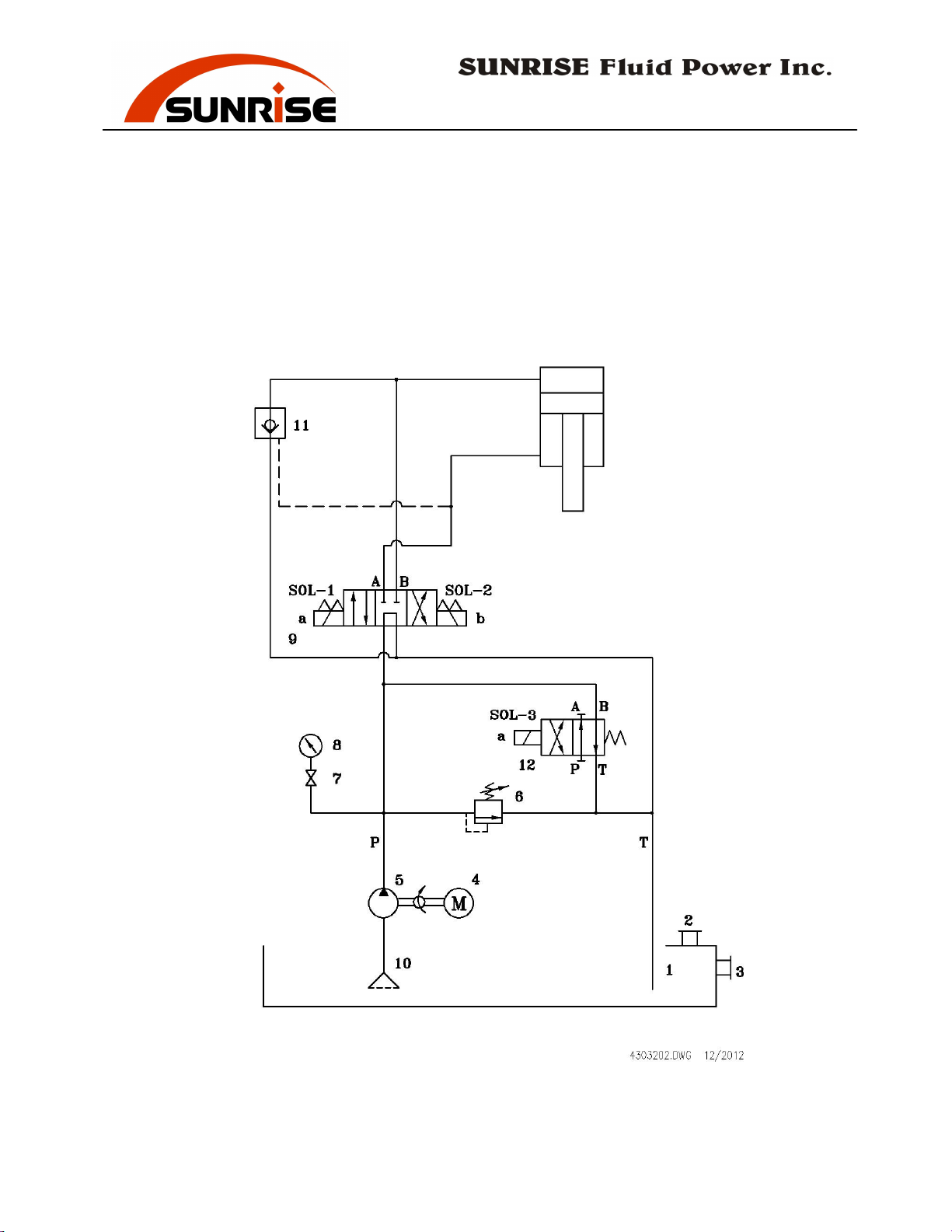
Hydraulic Circuit Parts
PM-55, PM-80
(with low pressure JOG)
- 32 -
Page 35
No. 7, Road 12, Industrial Zone, Taichung City 407, Taiwan
Tel: 886-4-2359-1190 [email protected]
Fax: 886-4-2359-3409
www.sunriseiw.com.tw
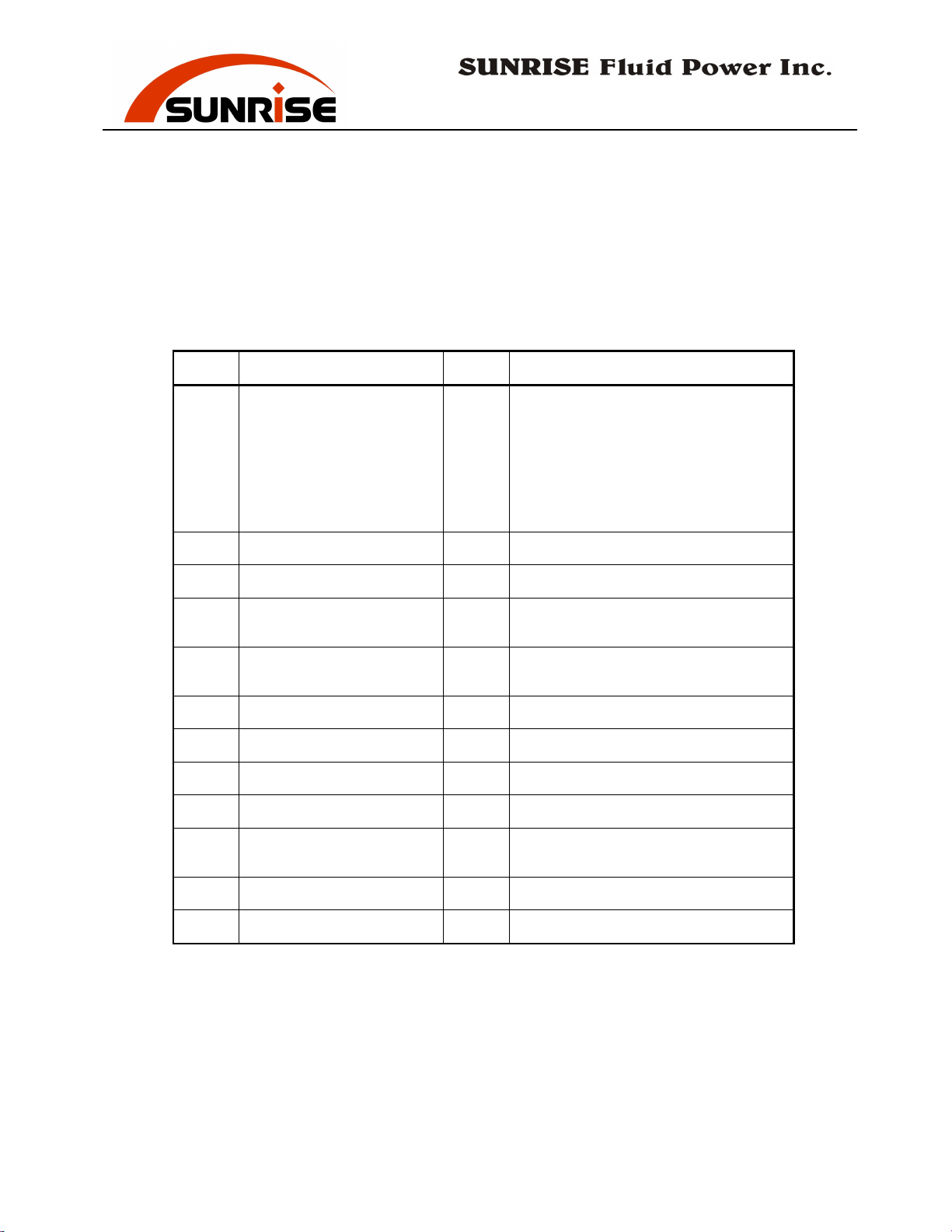
Hydraulic Circuit Parts
PM-55, PM-80
(with low pressure JOG)
No. Description Qty Specification / Part No.
PM-55T : 214302930 (JOG)
PM-55LT: 214402930 (JOG)
Tank 1
1
PM-55XT: 214502930 (JOG)
PM-80T : 214602930 (JOG)
PM-80LT: 214702930 (JOG)
PM-80XT: 214802930 (JOG)
2
3
4
5
6
7
8
9
10
11
12
Breather & Filter 1 53702HY08A
Oil Level Gauge 1 53701LG4
Motor 1
Pump 1
PM-55: 5 HP
PM-80: 7.5 HP
PM-55: 53201ALP2AS16
PM-80: 53201GHP2AS25
Relief Valve 1 53656RPECFAN
Gauge Cock 1 53652ST02L
Pressure Gauge 1 53621CBLM63350
Solenoid Valve 1 53651DFA03003
Suction Oil Filter 1
PM-55: 53301MF086
PM-80: 53301MF106
Check Valve 1 53654CKEBXCN
Solenoid Valve 1 53651DFA02001
- 33 -
Page 36
No. 7, Road 12, Industrial Zone, Taichung City 407, Taiwan
Tel: 886-4-2359-1190 [email protected]
Fax: 886-4-2359-3409
www.sunriseiw.com.tw
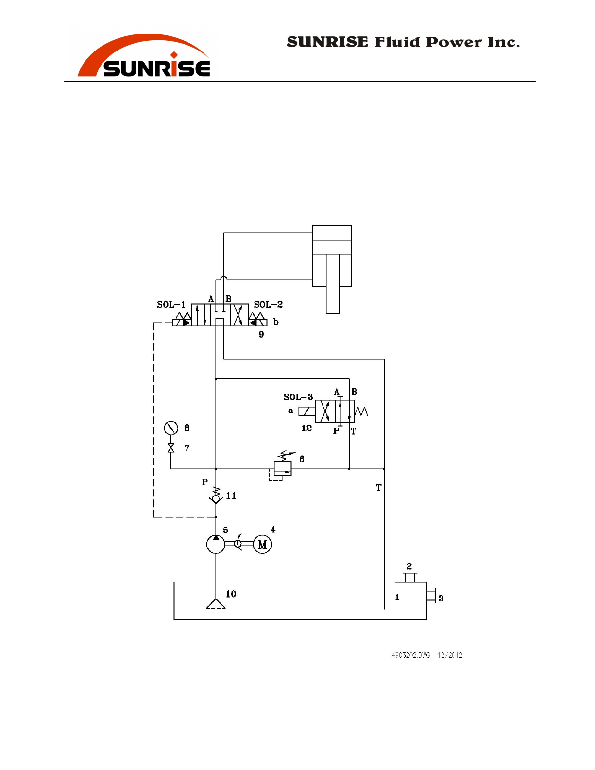
Hydraulic Circuit Parts
PM-120, PM-160, PM-200
(with low pressure JOG)
- 34 -
Page 37
No. 7, Road 12, Industrial Zone, Taichung City 407, Taiwan
Tel: 886-4-2359-1190 [email protected]
Fax: 886-4-2359-3409
www.sunriseiw.com.tw
Hydraulic Circuit Parts
PM-120, PM-160, PM-200
(with low pressure JOG)
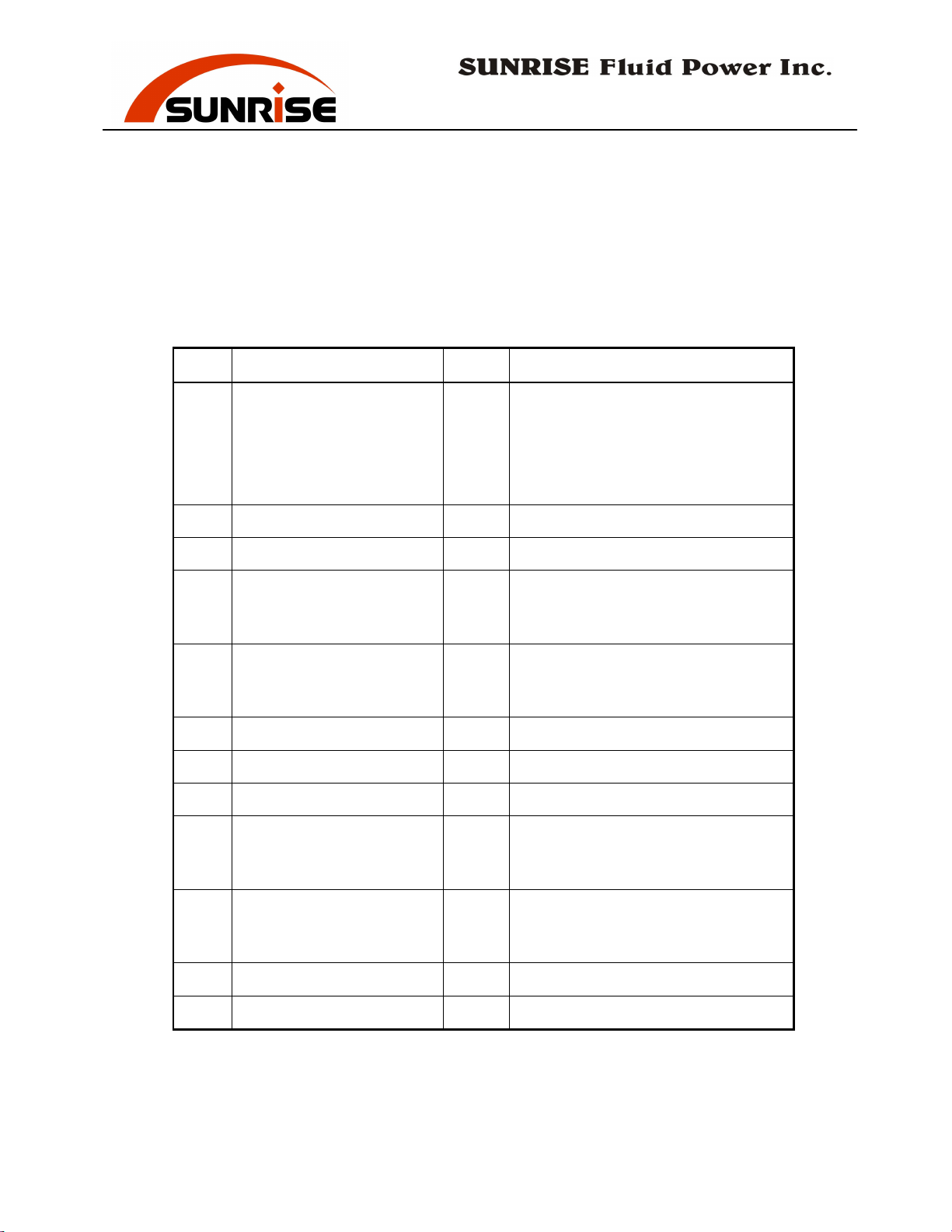
No. Description Qty Specification / Part No.
PM-120LT/XT: 214902910A
PM-120T:215502910
Tank 1
1
Breather & Filter 1 53702HY08A
2
PM-160: 215102910A
PM-200LT: 215302910B
PM-200XT: 215402910
3
4
5
6
7
8
9
10
11
Oil Level Gauge 1 53701LG4
PM-120: 10HP
Motor 1
PM-160: 15HP
PM-200: 20HP
PM-120: 53201GHP2AS34
Pump 1
PM-160: 53201SAL236
PM-200: 53201SAL250
Relief Valve 1 53656RPECFAN
Gauge Cock 1 53652ST02L
Pressure Gauge 1 53621CBLM63350
PM-120: 53651DSHG04001
Solenoid Valve 1
PM-160: 53651DSHG04001
PM-200: 53651DSHG06003
PM-120: 53301MF106
Suction Oil Filter 1
PM-160: 53301MF128
PM-200: 53301MF128
Check Valve 1 53654CIT065030T
Solenoid Valve 1 53651DFA02001
12
- 35 -
Page 38
No. 7, Road 12, Industrial Zone, Taichung City 407, Taiwan
Tel: 886-4-2359-1190 [email protected]
Fax: 886-4-2359-3409
www.sunriseiw.com.tw
- 36 -
Page 39
No. 7, Road 12, Industrial Zone, Taichung City 407, Taiwan
Tel: 886-4-2359-1190 [email protected]
Fax: 886-4-2359-3409
www.sunriseiw.com.tw
Electrical Parts
PM (CE)
(with low pressure JOG)
Code Description Quantity Function
QF Motor Circuit Breaker 1 Motor Protection
FU1,FU2,FU3 Fuse 3 Control Circuit Protection
FU4 Fuse 1 Spot Light Protection
QS Isolator Switch 1 Circuit Interrupter
SB1 Push-Lock Push Bottom 1 Emergency Stop
SB2 Flush Push Bottom (Red) 1 Pump Off
SB3 Flush Push Bottom (Green)
SA1 Selector Switch 1 Normal / Jog Key Switch
FS Foot Switch 1 Foot Switch Control
KA1 Relay 1 Ram Upward
KA2 Relay 1 Ram Downward
SQ1 Limit Switch 1 Ram Up Limit Switch
SQ2 Limit Switch 1 Ram Down Limit Switch
SQ3 Limit Switch 1 Punch Safety Interlock
SOL A Solenoid Valves 1
SOL B Solenoid Valves 1
KM
Magnetic Switch
(Contactors)
Bridge Rectifiers 1
Tr Transformer
1 Pump On
1
1
- 37 -
 Loading...