

Page 1
SUNRISE
Fluid Power Inc.
No. 7, Road 12, Industrial Zone,
Taichung City 407, Taiwan, R.O.C.
Tel: 886-4-2359-1190 Fax: 886-4-2359-3409
E-mail: awtkao@ms1.hinet.net
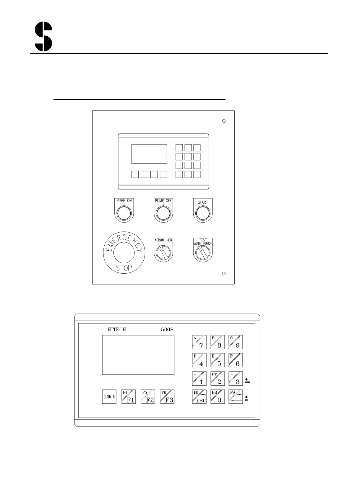
1. Buttons and Switches on the Controller Panel:
Page 2
SUNRISE
Fluid Power Inc.
No. 7, Road 12, Industrial Zone,
Taichung City 407, Taiwan, R.O.C.
Tel: 886-4-2359-1190 Fax: 886-4-2359-3409
E-mail: awtkao@ms1.hinet.net
Page 3

SUNRISE
Fluid Power Inc.
No. 7, Road 12, Industrial Zone,
Taichung City 407, Taiwan, R.O.C.
Tel: 886-4-2359-1190 Fax: 886-4-2359-3409
E-mail: awtkao@ms1.hinet.net
z Emergency Stop: Stop the machine in emergency.
z PUMP ON: start the motor
z PUMP OFF: stop the motor
z NORMAL/JOG switch: switch between cylinder normal movement
and jog movement (refer also to Operation Modes)
z AUTO/TEST/PUNCH switch (refer to section below on Operation
Modes)
z START: Run programs. Light flashes during program execution. If
any of the select switches is turned before the end of program, the
program stops.
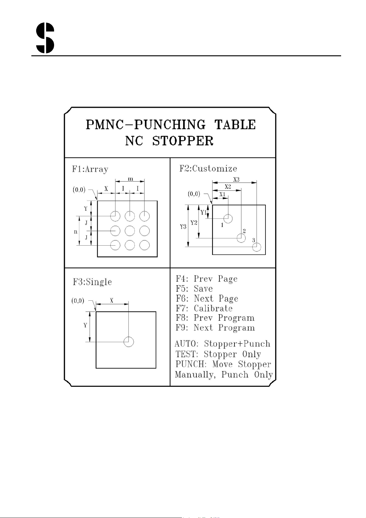
2. Opertion Modes:
AUTO: Run the program and execute punch. The Stoppers moves
automatically to next position after each hole is punched.
TEST: Run the program without punching. The stoppers moves
automatically to next position each time the foot paddle is pressed, but the
cylinder does not punch the hole. Use this mode to test the correctness of
the program.
PUNCH+NORMAL: Execute punch without using the NC stoppers.
This is like using the normal PM machine to punch holes. Use this mode
to check the correct setting of the stroke limit switches. In the mode, the
stoppers can be moved by the cursor keys, but cannot run programs.
PUNCH+JOG: The cylinder moves down when the foot paddle is pressed,
but does not move back up when the paddle is released. Use this mode for
checking the punch alignment each time the tool is changed. The NC
stopper does not function in this mode.
Note: in AUTO and TEST modes, the NORMAL+JOG is non-functional.
The cylinder moves only as Normal mode and not Jog mode.
Page 4

SUNRISE
Fluid Power Inc.
No. 7, Road 12, Industrial Zone,
Taichung City 407, Taiwan, R.O.C.
Tel: 886-4-2359-1190 Fax: 886-4-2359-3409
E-mail: awtkao@ms1.hinet.net
3. Operation Sequence
1) Turn on power. Be sure the emergency button is released. Screen
will be on after a brief self-check.
2) Be sure the stripper is closed.
3) Press Pump ON to start the motor
4) Turn to PUNCH+NORMAL mode and check the limit switch for
cylinder stroke adjustment is set correctly.
5) Turn to AUTO mode. The screen will prompt you for calibration
6) Press F6 (shift+F3) to calibrate the stoppers
7) After calibration, the screen switches to the function mode.
8) Press one of three type of programs (F1, F2, or F3)
9) In the Array or Cust program screen, press the program number to
call out the previously stored program, or use F8/F9 to move up/down
the program numbers.
10) In the desired program, enter the values for each of the parameter
fields. Use ESC and Enter keys to move up/down the parameter
fields.
11) Press F5 to store the parameter fields.
12) You may switch to TEST m ode to test run the program, or in AUTO
mode press START to run the program and execute punching. The
stoppers move to the first hole of the program.
13) If in TEST mode, press the foot paddle to move to next hole. If in
AUTO mode, press the foot paddle to execute the punch. After the
hole punching is completed, the stopper automatically moves to the
next hole (if any).
4. Calibration of NC stopper
Each time the power of the machine is turn on, you will need to first
calibrate the NC stopper. Press F6 (shift+F3) and the NC stopper will
calibrate itself. When the NC stoppers stops and screen switch to
Function screen, calibration is completed. If problem occurs, Err. 23
appears (refer also to section “Error Messages”). Press F7 (Shift+2) at
anytime to enter the calibration screen again.
Page 5
SUNRISE
Fluid Power Inc.
No. 7, Road 12, Industrial Zone,
Taichung City 407, Taiwan, R.O.C.
Tel: 886-4-2359-1190 Fax: 886-4-2359-3409
E-mail: awtkao@ms1.hinet.net
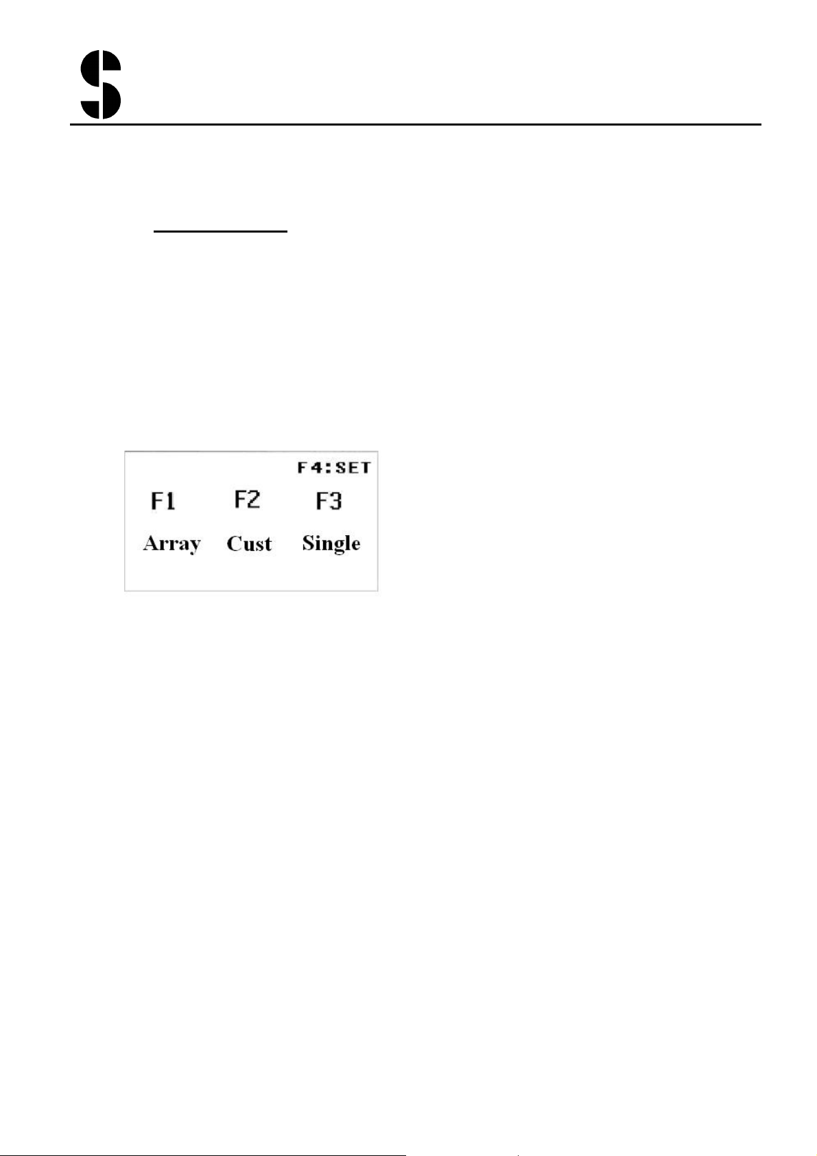
1. Function Screen
There are 3 types of programs available in the controller. Array program
is array program of holes. Up to 99 Array programs can be stored in the
controller. Cust program is a series of customized holes (up to 20 holes in
one program). Up to 25 Cust programs can be stored in the controller.
Single program is single hole punching. It is useful to move the stoppers
to a precise desired position. Single program cannot be stored.
Press F1 to enter the Array Program Screen
Press F2 to enter the Cust Program Screen
Press F3 to enter the Single Program Screen
Press F4 (Shift+F1) to enter the Setting Screen (password required)
You can press F1, F2, F3 at anytime to enter the program screens.
Page 6
SUNRISE
Fluid Power Inc.
No. 7, Road 12, Industrial Zone,
Taichung City 407, Taiwan, R.O.C.
Tel: 886-4-2359-1190 Fax: 886-4-2359-3409
E-mail: awtkao@ms1.hinet.net
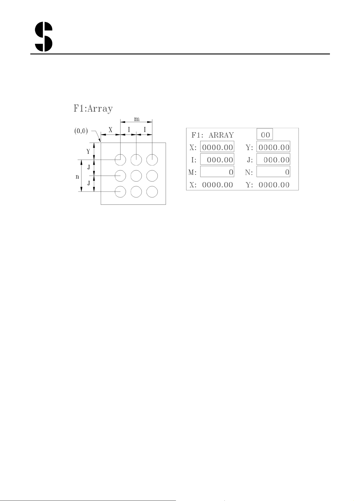
Use the ESC and Enter key to move to previous and next parameter field
and enter the value with the number pad. The allowed number range is
shown while entering the value.
Array Number (1 to 99) up to 99 sets of array program can be stored. Call
out any previously stored program by enter the array number.
F8 (Shift+ESC):Previous Array program number
F9 (Shift+enter):Next Array program number.
X:X-coordinates of the first hole
Y:Y-coordinates of the first hole
I:distance to the next hole in X direction
J:distance to the next hole in Y direction
M:number of holes in X direction
N:number of holes in X direction
X and Y in last line shows the current position of the NC stoppers
F5:Save the entry. If switch to other screen without press F5 first, then
the entered values are not saved.
Press START to execute the program, NC stopper moves to first hole.
Page 7
SUNRISE
Fluid Power Inc.
No. 7, Road 12, Industrial Zone,
Taichung City 407, Taiwan, R.O.C.
Tel: 886-4-2359-1190 Fax: 886-4-2359-3409
E-mail: awtkao@ms1.hinet.net
Use the ESC and Enter key to move to previous and next parameter field
and enter the value with the number pad. The allowed number range is
shown while entering the value.
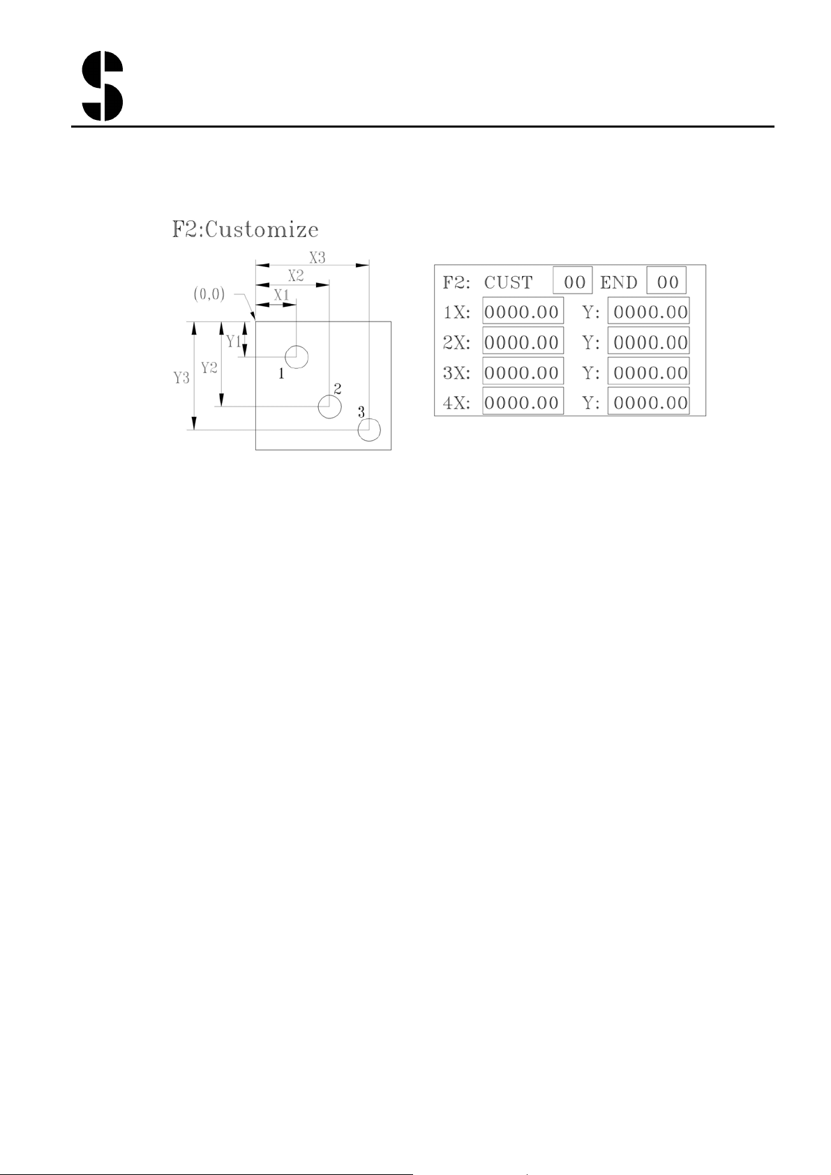
CUST Number (1 to 25) up to 25 sets of array program can be stored.
Call out any previously stored program by enter the array number.
F8 (Shift+ESC):Previsous CUST program number
F9 (Shift+enter):Next CUST program number.
1 X,Y:Coordinate of the first hole
2 X,Y:Coordinate of the 2nd hole
….
20 X,Y:Coordinate of the first hole
Up to 20 holes can be stored in one Cust program, but only coordinates of
4 holes are shown on the screen at one time.
F6 (Shift+F3) : Next Page (next 4 holes)
F4 (Shift+F1) : Previous Page (previous 4 holes)
END: enter the value indicate the number of holes in this Cust program.
Example: END=3, then only the first 3 holes (1X,1Y), (2X,2Y), (3X,3Y)
will be punched when running this program.
F5:Save the entry. If switch to other screen without press F5 first, then
the entered values are not saved.
Press START to execute the program, NC stopper moves to first hole.
Page 8

SUNRISE
Fluid Power Inc.
No. 7, Road 12, Industrial Zone,
Taichung City 407, Taiwan, R.O.C.
Tel: 886-4-2359-1190 Fax: 886-4-2359-3409
E-mail: awtkao@ms1.hinet.net
Use the ESC and Enter key to move to previous and next parameter field
and enter the value with the number pad. The allowed number range is
shown while entering the value.
X,Y:Coordinate of the hole
Note: X and Y in last line shows the current position of the NC stoppers
Press START to execute the program, NC stopper moves to hole.
Page 9
SUNRISE
Fluid Power Inc.
6.
Manually move the NC stoppers
No. 7, Road 12, Industrial Zone,
Taichung City 407, Taiwan, R.O.C.
Tel: 886-4-2359-1190 Fax: 886-4-2359-3409
E-mail: awtkao@ms1.hinet.net
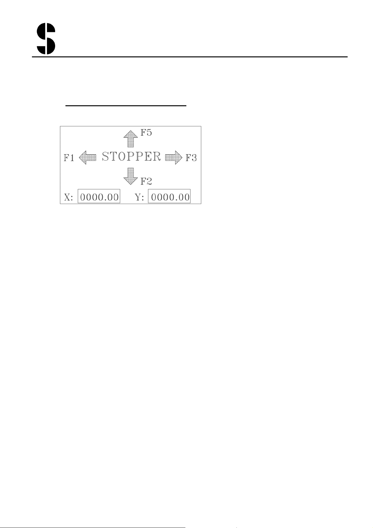
Turn to PUNCH mode and the screen switches to the manual mode. Use
the cursor to move the stoppers. Current position of the stopper is shown
on screen.
F1:Move the X-stopper to left(X-Axis value increase)
F2:Move the Y-stopper toward you(Y-Axis value decrease)
F3:Move the X-stopper to right(X-Axis value decrease)
F5 (Shift+F2):Move the Y-stopper away from you(Y-Axis value
increase)
X,Y:Current position of the NC stoppers
Page 10

SUNRISE
Fluid Power Inc.
7.
Setting Screen
No. 7, Road 12, Industrial Zone,
Taichung City 407, Taiwan, R.O.C.
Tel: 886-4-2359-1190 Fax: 886-4-2359-3409
E-mail: awtkao@ms1.hinet.net
WARNING:
incorrect entry of these setting parameters may result to
malfunctioning of the table or even damage of the table. The setting are
preset in factory before shipment, and should be changed only by
qualified maintenance/service personnel.
I)
If the origin point is off, or you need to adjust the software
protection of X and Y travel range (min and max of X and Y table
travel), you will need to change the parameters in the travel setting
screen.
To enter the setting screen (Password Protected), press F4 and you
will be prompted for password. Enter
and following setting
7777
screen appears:
F8: previous setting page
F9: next setting page
X-s:Set the value of the X stopper after calibration.
Y-s:Set the value of the Y stopper after calibration.
Mi(X)/Mi(Y):Set the minimum value of X and Y stopper travel range.
Ma(X)/Ma(Y):Set the maximum value of X and Y stopper travel range
These Min/Max values are also call the software travel range.
Page 11

SUNRISE
Fluid Power Inc.
No. 7, Road 12, Industrial Zone,
Taichung City 407, Taiwan, R.O.C.
Tel: 886-4-2359-1190 Fax: 886-4-2359-3409
E-mail: awtkao@ms1.hinet.net
To enter the motor parameter setting screen
II)
prompted for password. Enter
and following setting screen appears:
6666
press F4
and you will be
Tolerance level: this is the tolerance level allowed for the difference
between the programmed value compared to the actual value. If the
difference is greater than the tolerance level, then the set value, the
program stops and the Error screen is shown.
Motor Frequency: Set the motor frequency. (unit: pps)
Acceleration/Deceleration Time: Set the motor acceleration/deceleration
time. (unit: ms)
Press F4 to exit the setting screen.
Page 12

SUNRISE
Fluid Power Inc.
8.
EURROR MESSAGE
No. 7, Road 12, Industrial Zone,
Taichung City 407, Taiwan, R.O.C.
Tel: 886-4-2359-1190 Fax: 886-4-2359-3409
E-mail: awtkao@ms1.hinet.net
Error 11: When the movement of the cylinder is required but the pump is
not turned on.
Solution: Press “pump on” to turn on pump.
Error 12: Before execute a program, the cylinder needs to be at the top
position. If the cylinder is not in top position (e.g. cylinder moved down
in JOG mode) and the “Start” is pressed, Err 12 is shown.
Solution: Turn the switch to “punch” to move the cylinder to top position.
Error 13: The Stripper is open. For safety reason, the machine will not
move when the stripper is open.
Solution: close the stripper.
Page 13

SUNRISE
Fluid Power Inc.
No. 7, Road 12, Industrial Zone,
Taichung City 407, Taiwan, R.O.C.
Tel: 886-4-2359-1190 Fax: 886-4-2359-3409
E-mail: awtkao@ms1.hinet.net
Error 14: In Array mode, the value of M and N cannot be 0.
Solution: Press F1 to Array screen, enter values greater than 1 for M and
N parameter.
Error 15: In Custom mode, the value of the END cannot be 0.
Solution: Press F2 to CUST screen, enter values greater than 1 for END
parameter.
Error 21: The Stopper has reached the Hardware Min or Max travel range
allowed (set by proximity switches).
Solution: Select PUNCH mode. Use cusor key (F1, F3, F2, F5) to move
the NC stopper away from the Min or Max position.
Page 14

SUNRISE
Fluid Power Inc.
No. 7, Road 12, Industrial Zone,
Taichung City 407, Taiwan, R.O.C.
Tel: 886-4-2359-1190 Fax: 886-4-2359-3409
E-mail: awtkao@ms1.hinet.net
Error 22: The Stopper has reached the software Min or Max travel range
allowed (set by Mi/Ma parameters in SET screen).
Solution: Select PUNCH mode. Use cusor key (F1, F3, F2, F5) to move
the NC stopper away from the Min or Max position.
Error 23: In Calibration, the NC stopper is not able to find the origin
position after certain time.
Solution: check the origin proximity switch to see if the contact piece is
positioned too far or if the switch is broken. Turn power off then turn on
power again to reset the controller and try to calibrate again. If problem
persists, contract Sunrise agent for repair.
Error 24: During running an ARRAY program, the difference between the
actual position and programmed position is greater then the tolerance level
(set in Setting screen).
Solution: Check if there is any obstruction on the NC stopper to prevent it
from moving smoothly (e.g. stopper need to push too heavy a plate).
Press F1 to leave the error. Note: if the tolerance level is set too small,
this error may happen more frequently.
Page 15

SUNRISE
Fluid Power Inc.
No. 7, Road 12, Industrial Zone,
Taichung City 407, Taiwan, R.O.C.
Tel: 886-4-2359-1190 Fax: 886-4-2359-3409
E-mail: awtkao@ms1.hinet.net
Error 25: During running an CUST program, the difference between the
actual position and programmed position is greater then the tolerance level
(set in Setting screen).
Solution: Check if there is any obstruction on the NC stopper to prevent it
from moving smoothly (e.g. stopper need to push too heavy a plate).
Press F2 to leave the error. Note: if the tolerance level is set too small,
this error may happen more frequently.
Error 26: During running a SINGLE program, the difference between the
actual position and programmed position is greater then the tolerance level
(set in Setting screen).
Solution: Check if there is any obstruction on the NC stopper to prevent it
from moving smoothly (e.g. stopper need to push too heavy a plate).
Press F3 to leave the error. Note: if the tolerance level is set too small,
this error may happen more frequently.
 Loading...