

SunReports Apollo1 Quick Start Manual
Page 4 Copyright © 2010, SunReports. All Rights Reserved
20100823
we help you monitor:
solar electric
solar hot water
solar pool
heating
for more information go to:
www.sunreports.com
RealizeYourPower
SunReports
TM
www.sunreports.com
bay area
Printed using 30% post consumer recycled content by:
www.bayareagreenprinting.com
Notes
Apollo1
Quick Start Guide
Solar Thermal Systems
For detailed instructions, see the
Apollo Installation Manual from www.sunreports.com
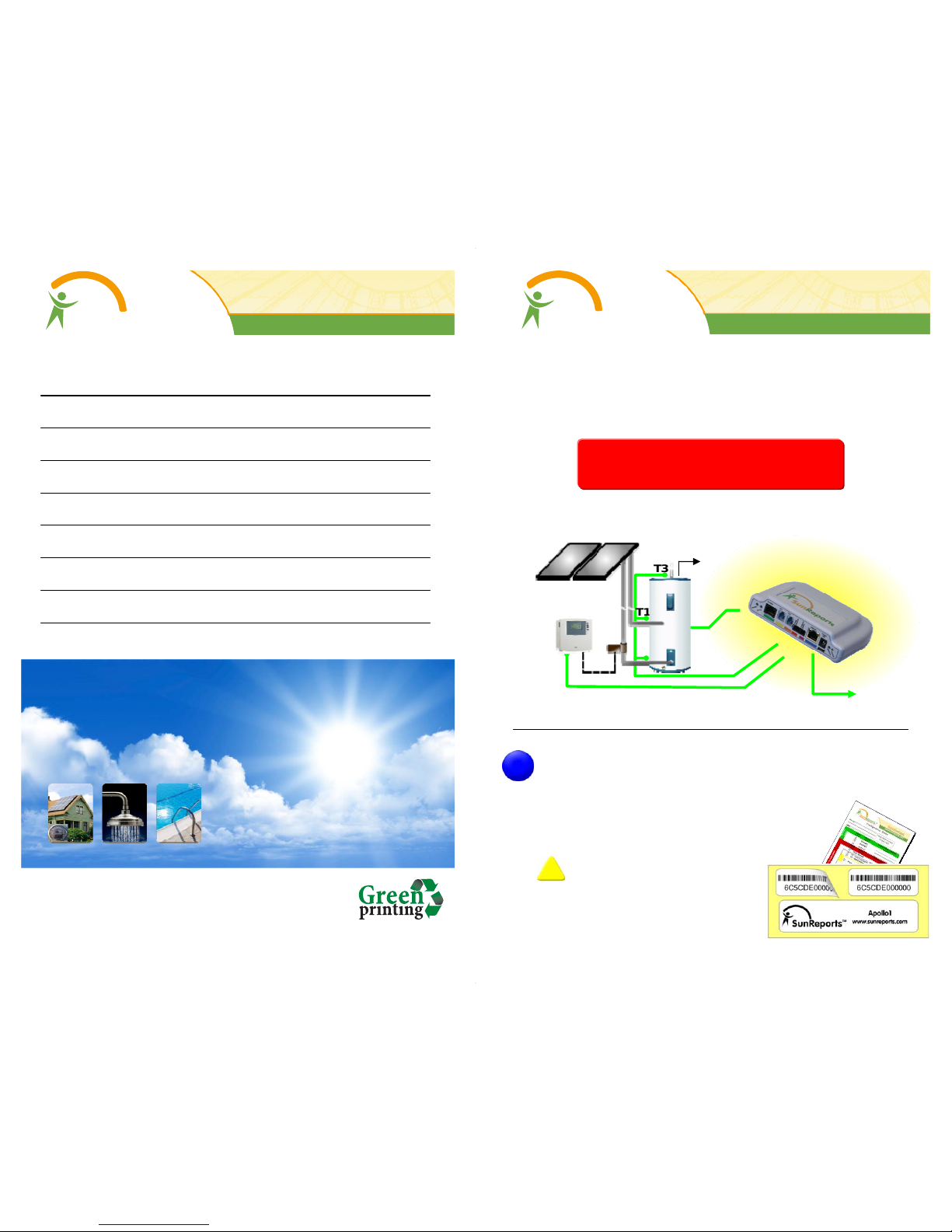
Add one serial number sticker from the
box to the Configuration Sheet
One sticker may be left with the end
user for their records
IMPORTANT: The serial number
entered into the on-line system
MUST match the number on the
unit. This is what allows for the
mapping, identification and
environmental information
Page 1
RealizeYourPower
SunReports
TM
www.sunreports.com
!
1
General Configuration
Hot Water
to Building
T1
T3
T2
Page 2
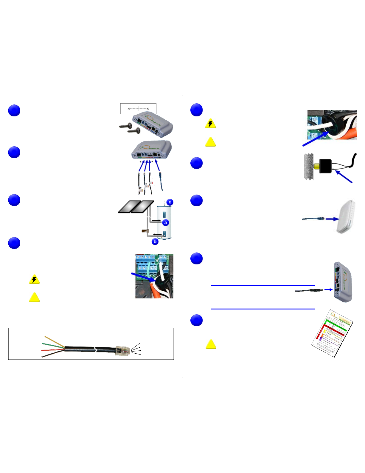
Find a suitable location to mount and
install the Apollo unit.
Note: Ensure the cables and power supply
will reach their destinations
Note: The mounting template is included
on the Configuration Sheet
Connect the cables to the Apollo unit by
simply matching the color coding.
Note: The following are optional:
- CT2 cable (orange)
- The Pressure Switch Cable (violet)
The following is not needed:
- Inverter Cable (green)
Connect the temperature sensors using
the provided zip-ties:
a) T1 to the Heat Exchange Input
b) T2 to the Heat Exchange Output
c) T3 to the Hot Water Output
The CT1 input is required for BTU calculations.
There are two options:
1. Current Transformer (detect pump On/
Off): Connect CT1 to ONE of the AC
pump leads at the controller box.
DANGER: Ensure power is disconnected
to the circuit before connecting the CT
IMPORTANT: Ensure only ONE side of
the AC power is routed through the CT
2. Flow Sensor (Grundfos VFS Series):
Connect CT1 to the flow sensor using the adapter cable.
!
2
3
4
5
4P4C (RJ9) to Apollo
Pin4 (Yellow - +5V)
Pin3 (Green - GND)
Pin2 (Red - Flow)
Pin1 (Black - NC)
Adapter Cable for
Grundfos VFS Series Flow Sensors
Pin1 (Yellow - NC)...
Pin2 (White - Flow).
Pin3 (Green - GND).
Pin4 (Brown - +5V)....
To Grundfos VFS
Optional: Connect CT2 to the electric
reheat coil.
DANGER: Ensure power is disconnected
to the circuit before connecting the CT
IMPORTANT: Ensure only ONE side of
the AC power is routed through the CT
Optional: Connect the Pressure Switch
cable to the system's pressure switch
Note: The polarity of the connections does not matter
Pressure switch sold separately
Connect the Blue CAT5 Internet
cable to a router with an 'always on'
Internet connection
Note:
If the router is located far from the Apollo unit, the following
options can be used:
- PLC Bridge (uses the AC wiring in the home to connect)
Available from SunReports
- Longer CAT5E patch cable (up to 300ft)
Connect power to the unit using the supplied
AC/DC Adapter. Verify the Apollo starts up
correctly and successfully connects to the
SunReports Server
Startup Routine:
- All Lights come on for a moment
- The 'Internet' light flashes while connecting
- The 'Internet' light turns solid on when connected
Record the customer information and
sensor label names on the included
Configuration Sheet
IMPORTANT:
This information will be
needed to properly set up the unit on
www.sunreports.com
7
!
8
10
Page 3
!
6
9
 Loading...