

Page 1
Assembly and Installation Manual
SOLFLO Solar Pool Pumps
Phone: (855) 372-8467 Email: Service@SunRayUS.com
Page 2

SOLFLO Pump Assembly Instructions
1. Remove pump base from shipping box and place on
a flat surface.
2. Rest the pump end on the base and align the two
feet over the two mounting holes.
3. Place the stainless steel flat washers over the base
flanges on each side of the pump. Insert the two
stainless steel screws and start the two base
mounting screws by hand.
4. Make sure the pump is straight in the base and the
screws are aligned vertical before tightening.
5. Tighten the screws until it just touches the base and
then turn it an additional 1/4 turn. Do not over
tighten the screws in the plastic base. If you see the
stainless washer bend then that is too much.
Page 3
SOLFLO Pump Assembly Instructions
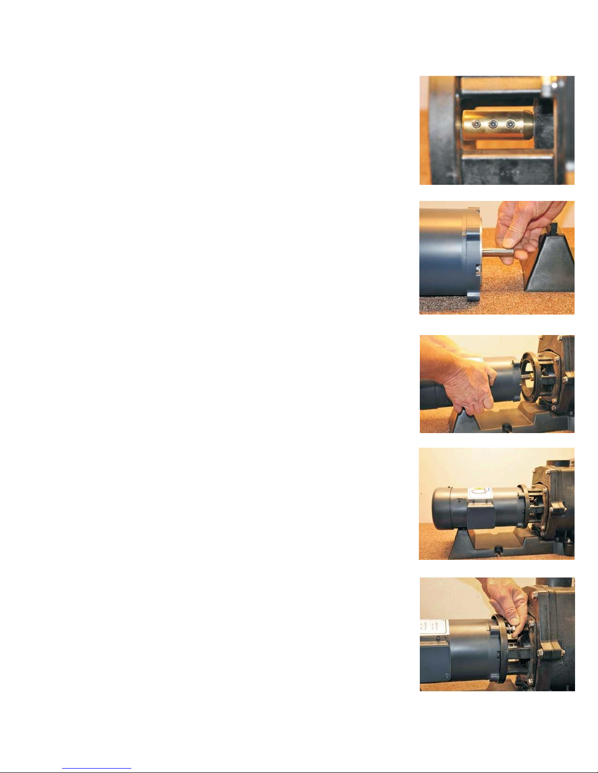
6. Rotate the pump shaft adapter until the set screws
are aligned to the center of the motor adapter slot.
This will be about a 45 degree angle.
7. Rotate the motor shaft until the key way is at the
same 45 degree angle to align with the pump
coupling set screws. Apply a small amount of never
seize or grease to the motor shaft before inserting
into coupling.
8. Install the motor by guiding the motor shaft inside
the pump coupling. Make sure the key way aligns
with the set screws.
9. Slide the motor toward the pump until it touches
the motor adapter.
10. Install the four 3/8-16 motor bolts through the
motor adapter into the motor and tighten.
Page 4

SOLFLO Pump Assembly Instructions
11. Now the impeller and the pre-load on the shaft seal
needs to be adjusted. With a large flat point screw
driver, pry the motor shaft coupling toward the
motor until it stops. Then back it off about 1/8”.
12. While holding the pump shaft in position with the
screw driver, insert a 1/8”Allen wrench into one of
the set screws and tighten. You can then remove the
screw driver and tighten the other two set screws.
13. Your pump is now assembled and the impeller and
shaft seal is adjusted properly. It is now ready for
installation.
SLOFLO SERIES POOL PUMP
Installation & Operating Instructions
GENERAL
Your pump has been engineered to give maximum efficiency under normal pool water
pumping applications. Consult the manufacturer for any other applications.
INSTALLATION
I. LOCATION OF PUMP
Place pump on a firm level surface. The pump does not be need to be bolted down unless
required by local code. Select a location close to the filter allowing for convenience and
serviceability.
Page 5

II. PUMP CONNECTIONS
The suction line from the pool skimmer and main drain must be connected to inlet on the
hair and lint trap. It is recommended to have a minimum of 12” of straight pipe before
hair and lint trap. The discharge line to pool (return lines) must be connected to outlet at
top of pump. If the pump is installed below water level of pool, install valves on the inlet
and outlet piping to permit removing of equipment without draining the pool.
CAUTION: During the pressure test procedure, this pump is under pressure. DO NOT
LOOSEN the filter trap cap while pump is running or until all pressure is released. Raise
the pressure slowly. Do not exceed 35 psi. Extreme care must be taken during pressure
test. Failure to follow these instructions explicitly can result in personal injury.
OPERATION
I. PRIMING PUMP
At initial start-up, pump must be primed by filling hair and lint trap with water. To prime
pump, remove cover from hair and lint trap; fill pump and suction trap with water.
Replace cover (make sure the O-ring is in place) and tighten lock ring. Pump will now
prime, with priming time depending upon lift and horizontal distance of suction piping.
II. CLEANING BASKET
It is important to clean the hair and lint basket frequently. A dirty basket will reduce the
efficiency of the filter and heater and will put an abnormal stress on the pump motor,
which could result in costly repair bills.
CAUTION: Do not remove hair and lint strainer lid while pump is running or under
pressure! The lid can be removed or tightened by hand. Basket must be kept clear of
leaves and debris at all times.
III. REMOVING BASKET
1.) Turn off motor. 2.) Remove trap lid by rotating counter clockwise. DO NOT USE
TOOLS. 3.) Remove lid. 4.) Remove basket and empty debris. 5.) Replace basket, fill
with water, replace lid and lock ring securely to prevent air from entering and tighten.
DO NOT USE TOOLS 6.) Turn on motor.
NOTE: If pump is installed below water level of pool, close return and suction lines
prior to opening hair and lint pot. Make sure to re-open valves prior to operating.
DO NOT RUN PUMP DRY!
Always maintain proper water level in pool. If the water level falls below skimmer
intake, pump will suck air. Pump is equipped with a maintenance-free heavy-duty
mechanical seal. Damage will occur if pump runs dry, and warranty will be voided.
IV. TO PREVENT FREEZING
Drain liquid from pump through plug at bottom front section of volute. Make sure the
pump and filter equipment are completely empty to prevent freezing.
MOTOR
Your pump is equipped with a permanently lubricated, maintenance-free, industrial
quality motor designed to withstand the requirements of swimming pool application.
Page 6

Improper wiring can cause serious injuries and damage to the motor, voiding warranty.
(For wiring instructions, see system design diagram.)
NOTE: Motor is designed to withstand the effects of normal rainfall. To increase the life
of your motor, observe the following. However is it recommended to install the pump
out of the weather, if possible.
1.) Do not flood motor or submerge in water. To do so voids warranty.
2.) Provide ample cross ventilation, minimum of 6” at all points.
3.) Keep motor and surrounding area clean.
4.) Avoid sweeping or stirring dust near motor while it is running.
5.) Avoid storing or spilling dry chemicals, powders, etc., near motor.
6.) Provide protection against the elements.
7.) Locate motor on a slight elevation so water will drain away from motor.
8.) Avoid spilling or dripping liquid chemicals on or near motor.
9.) Avoid splashing water or hosing deck near motor. Water damage voids warranty.
For replacement parts or repairs, contact SunRay 1-855-372-8467.
WARNING – All electrical wiring of the motor installation must be done by a
qualified electrician in accordance with applicable electrical codes. Before working
on any motor be certain that the source of electrical power is off at the main junction
box.
GROUNDING WIRE – Upon installation of the pump, the motor must be
grounded with a No 8 AWG (8.4mm²) solid copper conductor per National Electric
Code. The connection should be from the accessible wire connector on the motor to
all metal parts of the swimming pool, spa, or hot tub structure and to all electrical
equipment, metal conduit, and metal piping within 5 feet (1.5mm) of the inside
walls of a swimming pool, spa or hot tub, when the motor is installed within 5 feet
of the inside walls of the swimming pool, spa, or hot tub.
Note: For electrical connections, see system wiring diagram.
TROUBLE SHOOTING
If pump looses prime, or if too many bubbles come through return line, check:
1.) Hair and lint pot cover is tight and O-ring is in place and free from defects.
2.) Valves on suction and return lines are working properly and open 3.) Water
level in pool is too low.
4.) Filter O-ring or gasket is in place and free from defects.
5.) All fittings and connections are secure and air tight.
Not pumping water, check:
1.) Filter pressure gauge reading too high, indicating filter needs cleaning.
2.) Clogged plumbing lines.
Page 7

3.) Clogged impeller.
4.) Worn or damaged impeller
Motor does not run, check:
1.) Fuses
2.) Incorrect or loose wire connections
3.) Output of the controller, if used. Disconnect the controller and connect panel wires
directly to the pump motor to see if the motor runs.
Power to the motor but it doesn’t run, check:
1.) Make sure motor shaft turns free.
2.) Jammed impeller or an obstruction in (volute) casing.
3.) Controller for proper output.
4.) Check the motor brushes to see if they are worn.
Motor overheating, check:
1.) Incorrect or loose wire connections
2.) Oversized solar panel array.
3.) Make sure the motor gets a fresh air supply and the vents are kept unclogged
Noises, check:
1.) Plumbing vibration
2.) Impeller turns freely and is properly adjusted
3.) Motor bearings
4.) For cavitation, due to obstruction in or undersized suction line.
For information regarding this pump contact:
SunRay Engineering LLC.
www.SunRayUS.com
Phone: (949) 636-4358 1-855-372-8467
Email: Sales@SunRayUS.com Service@SunRayUS.com
 Loading...