


User Guide
Air source heat pump water heater
Air Source Heat Pump
Domestic water
circulation series

Key Locking and Unlock
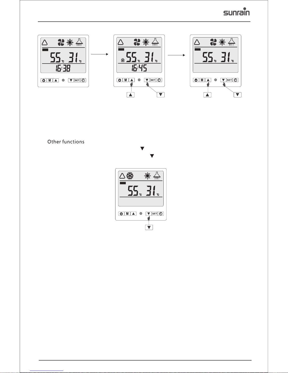
7.8 Other Functions
5. 4
Installation Scheme
0
0
0

1
Temperature ranges
A
m
The heat pumps are d esigned
Lasting
All units have high efficiency compressors with durable features which can withstand high temperatures
and high pressure. The tubes are placed in a shell heat exchanger which is durable against anticorrosion, hard water, high pressure and unexpected freeze caused by power cut-offs.
s
e
. A
a
ing the
temperatu re of the cir culating water. Voltag e protection, water coil and free ze protection.
at all times.
ensure
meets local safety reg ulations.
ensure that
to heat
not exposed
Anti-free zing measures must be impleme nted correctly to avoid damage to the water syst em and the
heat pump ex changer.
Please take i nto accou nt the heat pump size and we ight when transporti ng.
Ensure that the main source of power is off when installing.
material
Simple maintena nce and servicing
allation sp ace.
Strong Cabinet
s
monitorin g the

Produc t serial nu mbe r:Ⅰmeans th e first gen era tion , Ⅱ mea ns the seco nd genera tio n.
Identi ficatio n cod e of manufa cture: T me ans S unra in, T means Sun rain
X means wa ter circu lat ion air sou rce heat pu mp wa ter he ate r, refrig erant cir cul ation or
static h eating mo del o mitted
Heatin g capalit y, un it:L/h
C means fo reign tra de se ries air so urce heat p ump w ater h eat er, domes tic serie s omi tted
Auxili ary energ y cod e: D means av ilabel el ect ric er erg y, not code m eans no ele ctr ic energy .
F mean spl it and with out w ater tank t ype
K means ai r source he at pu mp, S mean wa ter sourc e hea t pump .
D means no rthern an d low t emperat ure type ai r sou rce he at pu mp, sourt hern and
common t upe omitt ed
KFC- 75 XTⅠ
KFC- 110XTⅠ
KFC- 15 0XTⅠ
3.51
0.93
4.23
1.35
6.14
5.35
1.37
6.23
2.0
9.0
75
0.75
110
m³/h
<54
936*385*550
936*385*550
1011*420*615
1100*520*740
1100*520*740
1180*560*815
Panasonic
1.99
9.0
2.7
12.3
150
7.4
2
GMCC
GMCC
Sunrain
Sunrain
220~ 2 40/1/50
R410a
R410a R410a
<54
<55
Rotary
Rotary
Rotary
55
60
1
55
60
1
55
60
1
1.1
1.5
Tube in shell
50
60
Dn20
Dn20
Dn20
Tube in shell
Tube in shell
60
40/48 55/65
65/79
IPX4
IPX4
IPX4
220~ 2 40/1/50
220~ 2 40/1/50

Water Outlet
Water Inlet
Power Cable Hole
Controller Cable Hole
Length (mm)
Wide (mm)
650
650
A (mm)Height (mm)Model
4. 2 Dimension
L
H
W
A
High Pressure Gauge
385
385
B (mm)
B
645
420
3
KFC-75XTⅠ
KFC-110X TⅠ
KFC-150XTⅠ
936
936
1011
385
385
420
550
550
615

Model:KFC -75XTⅠ
4

Model:KFC -110XTⅠ
5

Model:KFC -150XTⅠ
6
7

4.5 Components
Compressor
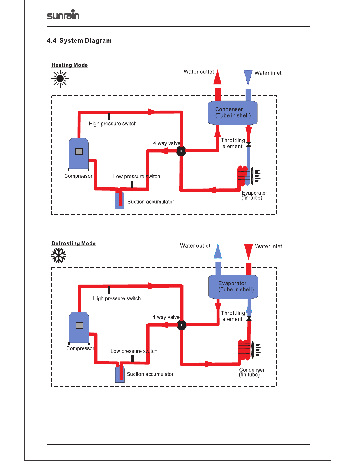
4-Way Valve
The reliable 4 way valve can
avoid gas mixing, and ensure
stable defrosting.
Condenser
Evaporator
ABS Plastic Fan
Photos Features/AdvantagesComponents
Circulation Pump
Famous brand water circulation
pump, e.g. .Grundfos
Refrigerant
LCD Controller
Intelligent controller with LCD readout
and automatical defrosting;
4-timer function available;
12 meter controller wire.
8
The dependable high efficiency compressor,
with optimized R410A system, can achieve
up to 60 degree temperatures, while
ensuring long life of the compressor.
R410A gas, environmental ly friendly
and of high per formanc e.
The tube-in-shell heat exchanger acts as a
condenser, with a bigger heat exchanging
area and greater efficiency for hot water
solutions.
The hydrophilic fin-tube heat exchanger
has a big heat exchanging area and
workable fin distance, thus significantly
improving the efficiency of heating and
defrosting.
The exterior motor fan, with multiple fan
blades. The fan is fixed firmly and its
blades run slower, making sure of high air
volumes while lowering the noise.

Accessories going together with the heat pump:
There are four casing options:
1. General casing: hot galvanised steel or cold steel casing with a powder coated.
2. hot galvanised steel casing with Electrophoresis treated in advance and powder coated. (This
is used for Sunrain domestic heat pumps. With thicker casing and special treated means, this casing
is much better on anti-rust performance.)
Special:
9
1 x SABS Approved Cobra Strainer 1 x Rubber Feet for Installation 1 x User Manual
1 x LCD controller 1 x Water-Proof Controller Box 1 x Wall-Mounted Controller Box
12m x Controller Wire
12m x Sensor Wire

10
uncomplic ated and al low for future access.
If the unit is to be install ed on the floor, the suppor ting fram ework should be mounte d to avoid
intake of water during r ainy seasons. In snowy a reas, it is i mportant to prevent ac cumulated snow
from blocki ng up the esc aping air. The recomm ended height is 20 – 30 cm.
A drain ditch or o ther faci lities should be arran ged under the outdoor un it to collect the water loss.
If installing the unit o n the balcony or roof, the i nstalla tion site must meet the al lowable bearing
capacity of the buildi ng structure, withou t comprom ising the structural s afety of th e unit.
Ensur e the unit is well ventilated, and th e direction of the air exhaust is kept away from windows
of neighboring buildings, and the exha ust air cannot flow back. Furthermore, adequate space sho uld
be available around the unit.
The unit mu st be install ed on a reliable base or framework. The framework should be 3 t imes the
weight of the u nit and safet y measures should be taken to avoid the m alfunctio ning of the fasteners.
Above ground i nstalla tions should be avoide d as much as possible as the u nit may fall and cause
injury
Do not install the heat pu mp close to a road or path to avoid the uni t getting splashed on. K eep
children aw ay from the h eat pump.

5.2 Water System Installation
5.2.1 Water Tank Installation
5.2.2 Water Piping Installation
1. The water tank should be put in place where suggested to install the heat pump, the water tank and
ambient temperature is higher. the circulation pump at the same level.
2. It can be installed either outdoors or on the
roof-top (some elements such as the size of
water tank and the bearing capability of the
building should be considered). Installation on
roof-top should be based on support such as a 4. Do not install the water tank in a pollutive or
crossbeam or pillar. corrosive area.
3.The water tank should not beplaced installed
lower than the base of the heat pump; It is
1. A
drainpipe and overflow pipe should be installed near
the gutter or the sinkhole for draining water more
efficiently. Discharge valve is necessary on the
drainpipe.
discharge valve is necessary on the drainpipe,
stop valve of the system (depending on the
ambient temperature) for avoiding icing of the
water supply pipe and the valves.
6. Keep the water pipes straight and the pipeline
2. Service valve needs to be installed before the
allocation reasonable; Reduce pipe turnings as
magnet-valves on the system pipeline for further
many as possible to reduce water resistance.
inspection.
7.Prevent the pipeline and the connectors from
3. The pressure of the water outlet should be
water leakage.
between 0.3MPa and 0.6MPa.
8.The water pressure bearing capability of each
4.It is recommended to use metal pipeline such
part of the piping system should be tested after
as stainless steel pipes, internal-plastic pipes,
the installation is finished; Drainage should be
internal stainless steel pipes or copper pipes etc;
done to create a clean interior system.
Telescopic issue of the pipeline between heat
9. Measures of heat preservation for the hot
pump unit and water tank should be considered if
water pipeline need to be conducted after
plastic pipeline such as PPR pipe and ABS pipe
assuring no water leakage.
etc. is used.
5. In winter, heat preservation may need to be
carried out on the water supply valve and the
Water
Tank
Water
Tank
11
In addition, the height difference between the heat
pump and the water tank should be no more than
2 meters, when the water tank position is higher
than that of the heat pump.

KFC-75XTⅠ
KFC-110X TⅠ
KFC-150XTⅠ
12
5.3

M
SET
M
SET
5.4. Wire Controller Installation
The wired controller is originally fixed on the maintenance door of the machine; please refer to the
to the steps below you want to install it on the wall:
?1.Take down the controller from the machine. The communication wire is connected with the circuit
board, separate them where they meet.
?2.Use a screwdriver to open the clip as picture 1, separate the controller as 2 parts, as picture 2.
?3.On the wall that you are going to install the controller, drill 2 holes at a level parallel to the sight line as
picture 3. The hole distance is 60mm, diameter is 8mm.
?4.Place the plastic screws of the enclosure into the hole, and use the tapping screw (ST4*16 D-1)
enclosed to fix the back cover of controller on the wall, as picture 4.
?5.Match the front and back covers perfectly, as picture 5, make sure that it is fixed firmly on the wall.
?6.Connect the communication wire firmly.
1 2
5
6
The front cover
60mm
Φ8
3 4
Outlet of the communication wire
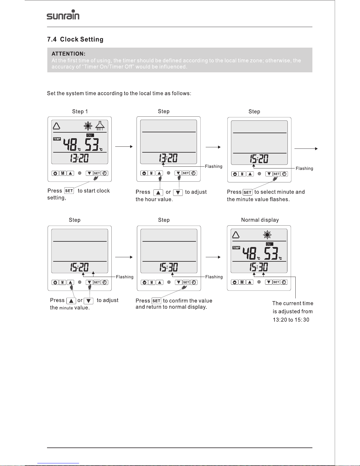
ATTENTION:
When the controller is fitted on the wall, don't pull the communication wire, or it may become loose.
The back cover
13

14
release
the
a professio nal
Comprehensive inspection of the entire
system should be a requirement, and ensure
that the water level inside the tank is higher
than the cycling heating outlet and the water
outlet, before the commissioning.
After turning on the electricity, turn on the
heat pump by pressing the on/off key on the
wire control panel.
es
making any ab normal
sounds.
the
Check the cir culatio n pump and all other parts
meet the requirement s. The whole system can
be put into use a fter the pr e-operation.

Menu button
Clock button
C
Timing button
Temperature s ≥
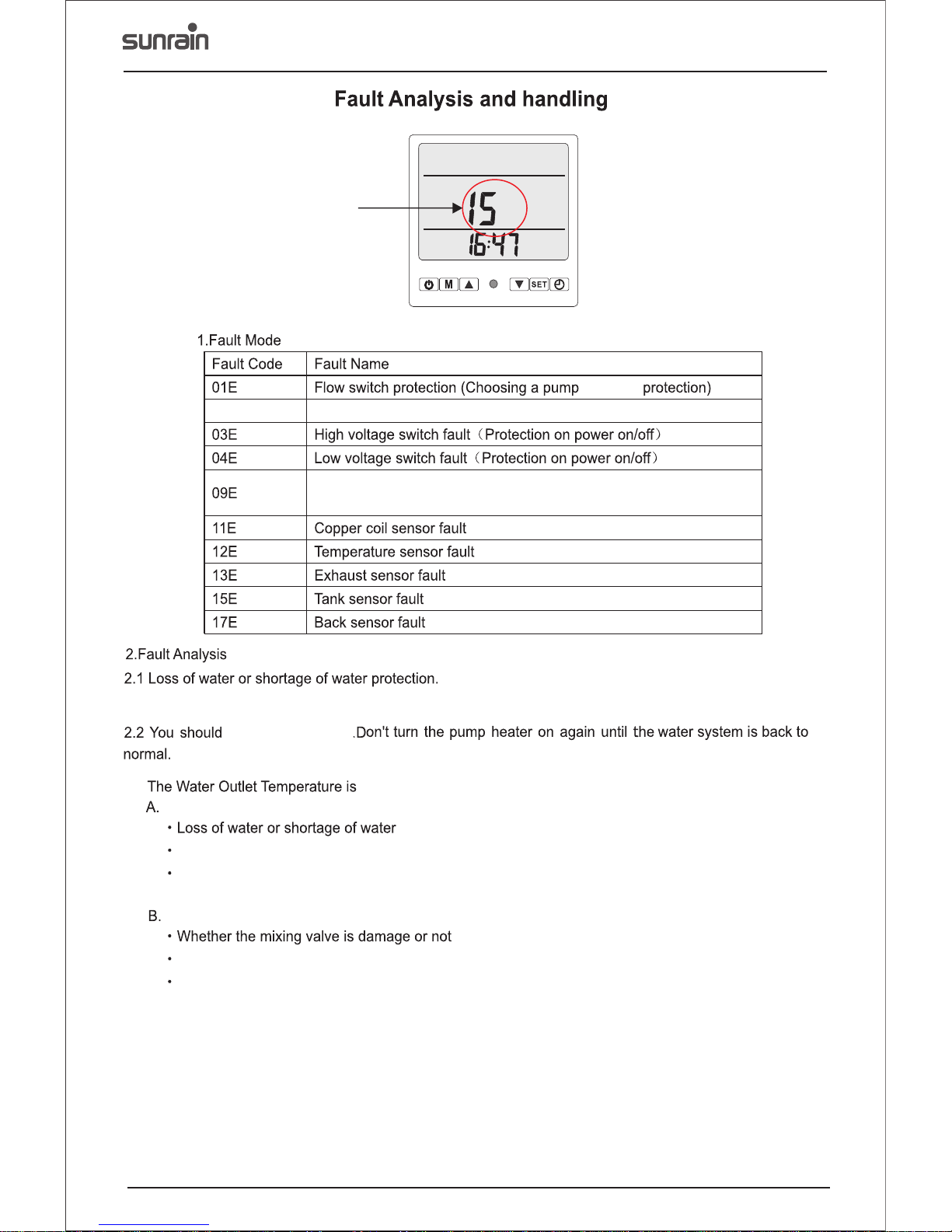
15
.
.
You can start or shut d own the con troller on the main inte rface.
to the main interface by p ressing the
When shutting down, pr ess the button for 5 secon ds
The menu button has both “ ”a nd “ ” , which ca n be used to see all options .
You can push the “M bu tton, S ET” button with “ button to set differ ent funct ions. When
starting, set the wate r temperature using th ese butto ns within a range of 28 – 55℃, the i nitial
value being 5 0℃.
” “ ”
On the main interface, press this button to set the clock and systematic parameters.
-
to the set temperature , will change the system .

1
1
compressor
16
ti mi ng stages
Timing button
Starting up electric heating in line with flashing
Starting up water pump, flashing
Starting up fan flashing.
2
3
4
5
17
“13:20"(the hour
ralue flashes)

Press the button or
button to set the Hour of the
timing time of turn on.
Press the button, it will
enter the setting interface
of the current timing phase.
Step1
Press the button, it will
enter the turn on/off timing
time checking interface.
Press the button, the
numbers which indicates
the Minute will twinkle.
Step2 Step3
Step4 Step5 Step6
Press the button or
button to set the Hour of the
timing time of turn off.
Press the button, it will
enter the setting interface
of the current timing phase.
7.5 ON/OFF Time Setting
7.5.1
7.5.2
7.5.3
7.5.4
7.5.5
7.5.6
7.5.7
7.5.8
18
On
screen
The time checking sc reen will display the st atus of the t iming phase1 and 2.
On
screen
After
After
h
m
the minutes of the time.
After setting the minu tes, re-press the ‘SET ’ but ton, it wil l show the screen to turn off the tim er.
After setting the turn off timer, r e-press the “SET” butt on to confi rm the current timing ph ase and
return back t o checkin g the turn off and on time r.
In the turn on/off tim er screen , press the button to confirm the cur rent set times and return
back to the on/off tim er.
turn on time.

SET
SET
SET
SET
Step1
Step1
Step1
Press button and
button for 5 seconds at the
same time, it will lock the
buttons.
Press button and
button for 5 seconds at the
same time, it will unlock the
buttons.
Long press th e button,
it will enter t he Compulso ry
deforstin g starus.
7.8
20
7.8.1 To check the defrosti ng status , press the“ ” button for a lon ger time.
7.8.2 To start the electric h eating, p ress the ‘M’ and “ ” button for a lon ger time. R epeat this or
turn off the machine t o cancel the electric he ating,
SET
SET
SET
SET
Step1
Step1
Step1
Press button and
button for 5 seconds at the
same time, it will lock the
buttons.
Press button and
button for 5 seconds at the
same time, it will unlock the
buttons.
Long press th e button,
it will enter t he Compulso ry
deforstin g starus.
7.8
20
7.8.1 To check the defrosti ng status , press the“ ” button for a lon ger time.
7.8.2 To start the electric h eating, p ress the ‘M’ and “ ” button for a lon ger time. R epeat this or
turn off the machine t o cancel the electric he ating,
KF C-75XTⅠ/ KF C- 110XTⅠ/ KF C- 150XTⅠ
21

9.1 Maintenance
Keep the surroundings of the heat pump dry, clean
and ventilated. Regularly clean the evaporator to keep
high heat exchanging efficiency.
Check the inside pipe connectors and refrigerant
service port are not dirty with oil. Make sure there is no
The external water filter should be cleaned regularly
refrigerant leakage.
to ensure the cleanness of the water in the system
and avoid damage caused by blockage in the filter.
and shut off thepower supply, and put it into a shield. Full
All protective settings in the unit have been set before inspection of the system is required before next
. Users must not adjust it when
heat pump
exiting the factory the operation.
unit is in use.
Users should call the installer or the seller when there
Regular inspection is required for the power source is an error on the heat pump controller.
and the wiring connection of the electric system. Loose
wiring connection and electric components should be
Clean the condenser with phosphoric acid of 15%
repaired in time.
consistence under temperature of 50C-60C. Run the
circulation pump for 3 hours, and then flush with fresh
water for 3 times. When installing the pipe, add a 3 way
valve on the pipes and add a cover for cleaning use.
Cleaning the condenser with a corrosive washing liquid
is prohibited.
Check the water pump and the valves on the pipes
, and make sure there is no work properly leakage
from connectors.
22
9. Maintenance and Trouble Shooting
The water supply system, relief valve of the water
tank, water level control device and air discharge
davice. Need to be checked regularly in case of low
circulation and low water volume, which is caused
by air entering the system. This is to ensure the
capacity and reliability of the heat pump.
Clean the inside of the water tank after it has been
used for a period of roughly two months (depending
on the quality of water).
Before turning off the heat pump for an extended
period of time, drain out all the water in the pipes,
The heat pump water heater is an advanced
equipment with high automization. The
reliability and operating life of the heat pump can
be and even increased by regular
inspection and effective maintenance.
guaranteed
E
23
Fault Mode
that has
Protectio n from high e xhaust temperature s
Communica tion faul t (Operation plate did n ot receiv e data from
the main boar d)
The pump heat er will sto p high pressure protec tion when there is a loss of w ater or sho rtage of water.
turn off the power.
2.3
If the water temperatu re is too high – you can inspe ct the pump heater as follows:
Whether the mixing val ve is damaged
Whether the line contr oller works abnormal ly. If it is a bnormally, please replace th e controller
immediate ly.
If the water outlet temp erature is too low – you can i nspect th e pump heater as follows
Whether the line contr oller works abnormal ly.
.
.
.
.
If the controller work s abnormally, pleas e refer to fa ult code or contact a prof essiona l.
2.4 When insp ecting th e fault protection, en sure the pu mp heater has stopped wo rking.
2.5 Af ter removing the fault , the compr essor will not work for an other 3 min utes. The pump heate r will
start to work again. It th ere appears to be low or hig h pressure protectio n or exhaus t temperature
protectio n for 3 minut es, the pump heater will s top worki ng. Af ter the problem has been r esolved the
pump heater w ill work af ter the power has been swi tched back on. If there is somethin g wrong with he
hot water sensor or defr osting sensor, the pump h eater wil l stop working. After rem oving the fault, the
compresso r does not wo rk for about 3 minutes. If t here is a fault with the temperatur e sensor the
pump heater w ill conti nue working.
irregular

24
9.7 Trouble Shooting
0
5
10
15
20
25
30
35
40
45
50
10
15
9.6 Manometer Instruction
Malfunction Possible Reasons Solutions Recommended
Heat pump unit is out of
operation.
1. Power source fault.
2. Loose connection of power wire.
3. Power fuse burnt out.
4. Low water level switch is not on.
1. Cut off the power source and check.
2. Check the power wire connection.
3. Check the fuse.
4. Supply water until the water level switch is on.
Water pump is running
but no water circulation
or much noise made by
water pump.
1. little water in the system
2. Air exists in the water system.
3. Some valves are not opened.
4. The water filters is blocked up.
1. Fill water into the water supply system.
2. Discharge air from the water system.
3. Open all the valves in the system.
4. Clean the water filter.
Low heating capacity.
1. Lack of refrigerant.
2. Faulty water system heat preservation
3. Low evaporator heat transferring.
4. Low water flow volume.
1. Leakage hunting and fix it,discharge all the
refrigerant and inject the right amount.
2. Improve the heat preservation.
3. Wash the evaporator.
4. Clean the water filter.
Heavy frosting, low
heating capacity.
1. The evaporator is too dirty.
2. Defrost sensor fault.
3. The 4 way valve can not change
direction.
4. Long defrosting duration
1. Wash the evaporator.
2. Change to a new defrost sensor
3. Check the solenoid if it is energized.
4. Change the temperature for entering defrost
and the duration.
High noise of
compressor.
1. Liquid refrigerant into the compressor.
2. Interior component of the compressor is
faulty.
1. Check if the thermostatic expansion valve is
faulty.
2. Change the compressor.
0
5
2
0
2
5
30
35
40
45
50
The Manomet er is high pr essure device that a hea t pump uses. When it is on, the Manomet er pointer
should poin t to the maxi mum pressur e value of th e refrigerant. The m aximum pr essure should be
42Kgs to allo w for safe us e. When the heat pump is off, the poi nter will show the ambie nt temper ature
(e.g. 28℃) and related air p ressure (e.g.18 k.g/ Cm)²
When restar ting the he at pump after not using it f or a while, p lease check the manome ter ambie nt
temperature is not sma ller than 2℃, If it is below 2℃, the n the refri gerant has leaked and yo u will
need to confirm with a pro fessional engineer a s soon as possible.
Users shoul d contact t he professional main tenance staff when there is a pro blem with the heat pump.
The maintenance tabl e below may be helpful whe n doing the troublesho oting.

25
Compressor is out
of operation.
1. Power source fault.
2. Compressor AC contactor
damaged.
3. Loose wire connection.
4. Over-heat protection.
5. Over-high water temperature
6. Low water flow volume.
1. Check the power source, change faulty components.
2. Change the contactor.
3. Check every wire connection of compressor.
4. Check gas leakage.
5. Bring down the water temperature value.
6. Clean the filter, check if there is air inside the water
system.
Fan is out of
operation.
1. Loose fan motor wire.
2. Burnt out fan motor.
3. Fan AC contactor fault.
1. Check every wire of the fan connection.
2. Change the motor.
3. Change the AC contactor.
Low water flow
volume protection.
1. Circulation pump fault.
2. Circulation pump is too small.
3. Water filter blockage.
4. Flow volume control device restore.
1. Check the operation of the circulation pump and fix it.
2. Change a bigger pump.
3. Wash the water filter.
4. Adjust or change the flow volume control device.
Over-high
compressor
discharge pressure.
1. Low water flow volume.
2. Thermostatic expansion valve
opening is broken /blocked.
1. Check the circulation pump,and the water filter.
2. Check and adjust the openings, or directly change the
expansion valve.
Over-low
compressor suction
pressure.
1. Not enough gas.
2. Large pressure drops through the
heat exchanger.
1. Check gas leakage.
2. Check and adjust the expansion valve openings.
Shortage of oil in
compressor.
Shortage of lubricant oil.
Find out the su itable ki nd of oil for the compress or and
Inject suitable type o il into the compressor.
Thermostatic
throttle valve can
not start.
1. The switch for it is not open.
2. Low water pressure, water pipe
diameter too small, pipe is too long.
1. Inspect the power source of the solenoid valve.
2. Check if there is blockage in the pipes, and add
boosting pump when necessary.
Malfunction Possible Reasons Solutions Recommended

Our company have the right of amending products and
specifications,and do not give any special notice.
If any fault or omission exiting in the proce ss of printing,
our company have the right of modificatio n momentarily.
Jiangsu Sunrain Solar Energy Group Co.,Ltd
Ma nu facturer : Gu an gd on g Solareast Air Source Energ y Co.,Ltd
Address: XinYue Road No:5-6, Shunde Zone. Foshan City, Guangdong Province.
Zip Code:528300 TEL:4008-603366 Website:www.sunrain.com
 Loading...