

Sunraele Off-Grid Inverter P 2-3kW Service Manual
SUNRAELE
Inverter/Charger
SUNRAELE Off-Grid Inverter P 2-3kW
Service Manual
Service Manual
SUNRAELE Off-Grid Inv P 2-3kW

Service Manual
1. General Information.................................................................................................... 1
2. Fault and Troubleshooting.......................................................................................... 3
3. Steps to Repair .......................................................................................................... 4
4. Other Common Faulty Cases......................................................................................23
SUNRAELE
SUNRAELE Off-Grid Inv P 2-3kW
Table of Contents
1.1 Brief Introduction ....................................................................................................1
1.2 Basic Topology Introduction....................................................................................1
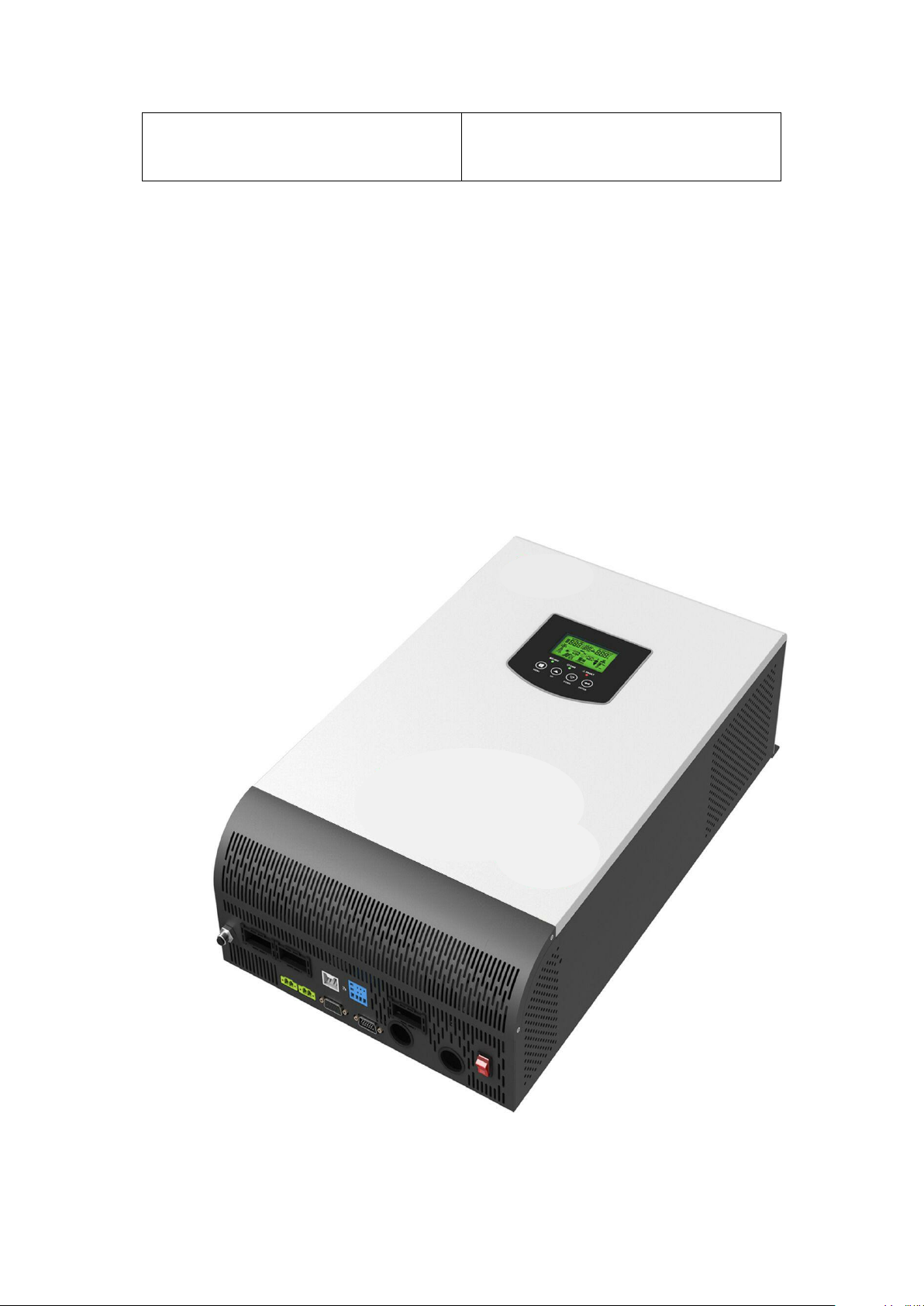
1.3 Overview of Inverter/Charger..................................................................................2
3.1 Maintenance...........................................................................................................4
3.1.1 To Check DC FUSE and Capacitance............................................................4
3.1.2 DC/DC Boost Module.....................................................................................5
3.1.3 Divers.............................................................................................................6
3.2 To Check BUS Module............................................................................................9
3.2.1 Rectifier Diode................................................................................................9
3.3 To Check Full Bridge Invert Circuit........................................................................10
3.3.1 Power Devices...............................................................................................10
3.3.2 Divers.............................................................................................................10
3.3.3 To Check Drivers............................................................................................12
3.4 To Check AC Charging Circuit................................................................................13
3.4.1 To Inspect Power Components as.................................................................13
3.4.2 To Check Drivers............................................................................................13
3.5 To Check Rectifier Circuit.......................................................................................15
3.5.1 Charging Circuit.............................................................................................15
3.6 To Check Power Circuit.........................................................................................16
3.7 To Check MOSFETS for Reversed Protection on DC Terminal.............................19
3.8 To Check NTC Circuit.............................................................................................20
3.8.1 NTC in position of HS3 plugs in position of SW1 on main board..................20
3.8.2 NTC1 under Transformer...............................................................................20
3.8.3 NTC in HS4...................................................................................................21
3.9 To Check Fan Driver Circuit ..................................................................................22
4.1 MOSFET Burnt.......................................................................................................23
4.2 Input Cable Disconnection......................................................................................23
4.3 Dust-covered Control Board...................................................................................24
5. Assembling Guidance..................................................................................................24
6. Test Guidance after Repairing.....................................................................................26
Service Manual
1. General Information
SUNRAELE
1.1 Brief Introduction
This manual is used as a tool of inspection and repairing guidance for
SUNRAELE Off-Grid Inv P 2-3kW, as well as instructions of assembling and
testing. It is best to have some electrical or electronic background knowledge.
With this guidance, hope it will help you to check and inspect the
inverter/charger first by yourself.
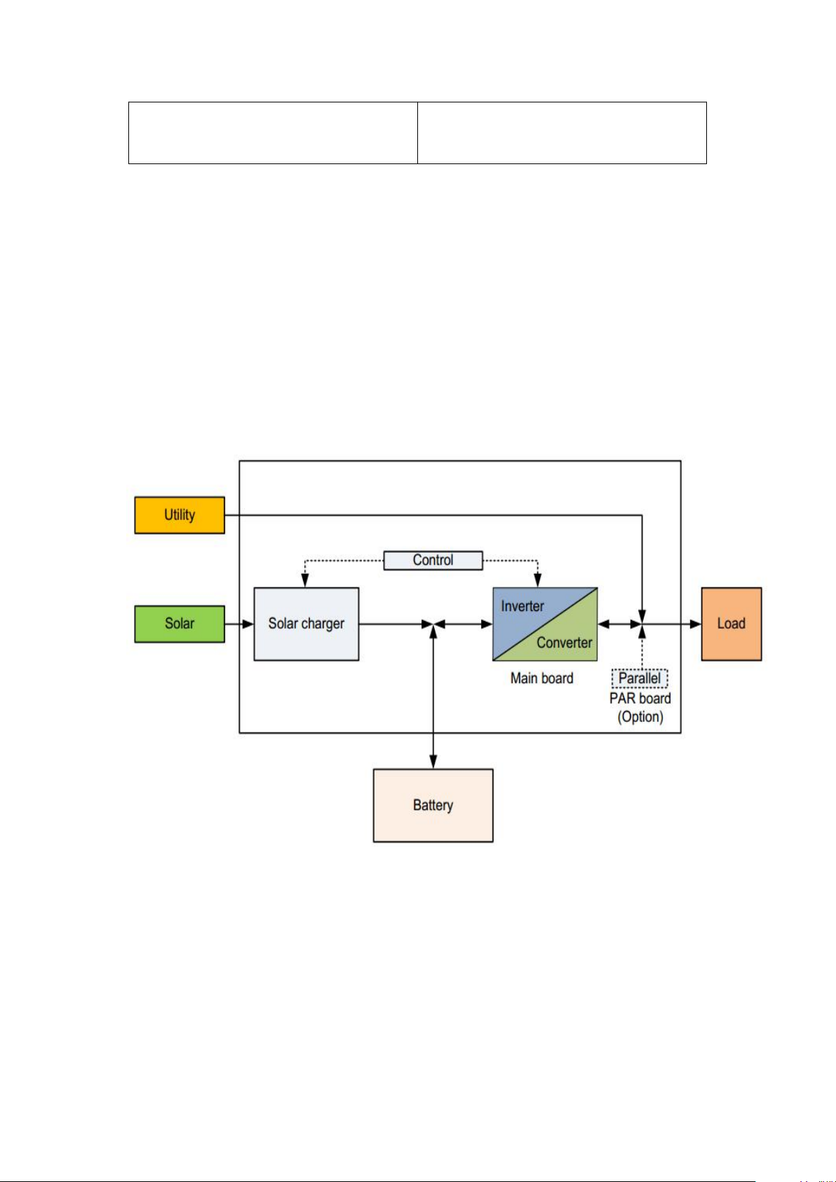
1.2 Basic Topology Introduction
The topology for 2KVA/3KVA shows as below:
SUNRAELE Off-Grid Inv P 2-3kW
- 1 -
Service Manual
SUNRAELE
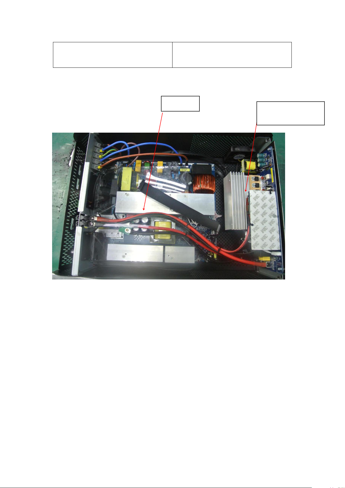
1.3 Over review and Introduction of Inverter /charger Parts
SUNRAELE Off-Grid Inv P 2-3kW
Main Board
Solar Charge Controller
& Control Board
- 2 -
SUNRAELE
2. Fault and Troubleshooting
Service Manual
SUNRAELE Off-Grid Inv P 2-3kW
No LCD
display when
inverter turns
on
01 First to replace the fan, to check whether it is okay; if NG, please
02 Please to check the main board and repair according to 3.8
03 Please to check first and then to repair the main board according
06 First to start up the inverter by only connecting battery, if the fault
08 To restart the inverter, to check whether the fault repeats, if yes, it
09 To Check the main board following 3.1.2, 3.2.1, 3.4.1 and 3.5 and
52 First to restart inverter by only connecting to battery, if fault
56 First to check the connection of battery cable, if good connection,
57 To replace the control board
58 First to restart inverter by connecting battery only, to check
72 To replace the control board
First to test battery volt to check whether it is in range of 44v-52v;
If it is in the range, to switch the inverter one to check whether the
unit starts. If the unit does not run yet, please disconnect all
connections and open the surface panel, take out the main board,
then to check and repair according to 3.7
inspect the main board and repair according to 3.9
to 3.1, 3.6 and 3.7
is still on, please inspect the main board following 3.3
requires to replace the control boards.
to repair accordingly
continues, then to check the main board according to 3.1.2 and
3.4
then please to check and repair the main board following 3.1.1
and 3.1.2 accordingly
whether it is good?
Second to connect battery and Utility but to keep switch off,
checking whether inverter charges battery? Otherwise, to check
and repair main board according to 3.1.2, 3.2.1 and 3.4.1
accordingly
- 3 -
- 4 -
3. Steps to Repair
3.1 Battery Working Mode Test
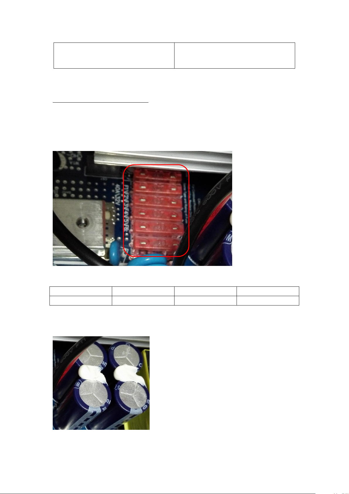
3.1.1 To Check DC FUSE and Capacitance
F1-F6: 180-00001-00 (Fuse, F40A/32VDC UL)
Positioning
Attribute
Reference Value
Failure Status
F1-F6
Resistor
0 ohm
open
C19,C20,C39,C40: 140-00093-00 (Electrolytic Capacitor, 4200uF 35V M RAD 7.5mm
105℃)
SUNRAELE
SUNRAELE Off-Grid Inv P 2-3kW
Service Manual
Service Manual
- 5 -
D
G
S
If the capacitors explode, they need to be replaced.
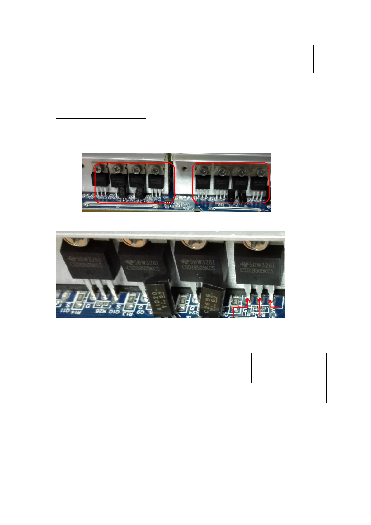
3.1.2 DC/DC Boost Module
150-00052-00:MOSFET TI/CSD19505KCS 201A 80V N BULK TO-220
Positioning
Attribute
Reference Value
Failure Status
All MOSFET, 8pcs
Diode
SD:0.44V
DS:OL
Short-circuit
or Explosion
Note If one or more than one of them were broken, please replace all of them. For 2K, the
main board has just 6pcs MOSFETS.
SUNRAELE
SUNRAELE Off-Grid Inv P 2-3kW
Service Manual
- 6 -
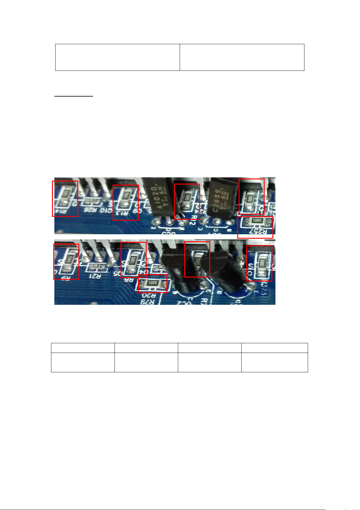
3.1.3 Divers
Note: when there are power devices or components are damaged, Divers are
usually required to check.
The reference resistors listed as below.
R373,R7,R8,R9,R10,R11,R12,R13,R14,R79,R257
All the resistors are 100-10010-00 (RES CHIP TF 1/4W 10 F(1206))
To use Multi-meter to measure each resistors till to find out the broken ones
and to replace them, no need to change all the resistors.
Positioning
Attribute
Reference Value
Failure Status
All Resistors:
10 ohm
Resistor
22 ohm
Open Circuit
or other value
If resistors are need to replace, please check the diver transistors and
controlling IC.
SUNRAELE
SUNRAELE Off-Grid Inv P 2-3kW
- 7 -
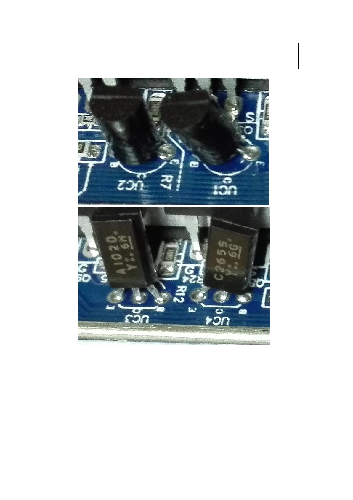
UC2,UC4:150-00005-00 (Plug-in Transistor TOSHIBA/2SC2655-Y 2A 50V)
UC1,UC3:150-00004-00 (Plug-in Transistor TOSHIBA/2SA1020-Y 2A 50V)
UC4
UC1
UC3
E
C
UC2
B
SUNRAELE
Service Manual
SUNRAELE Off-Grid Inv P 2-3kW
- 8 -
Pin16
Pin9
Pin8
Pin1
Positioning
Attribute
Reference Value
Failure Status
UC2,UC4
Diode
BE:0.6V
BC:0.6V
CE:1V
Short-circuit or burnt
UC1,UC3
Diode
BE:0.6V
BC:1.3V
CE:0.2V
Short-circuit or burnt
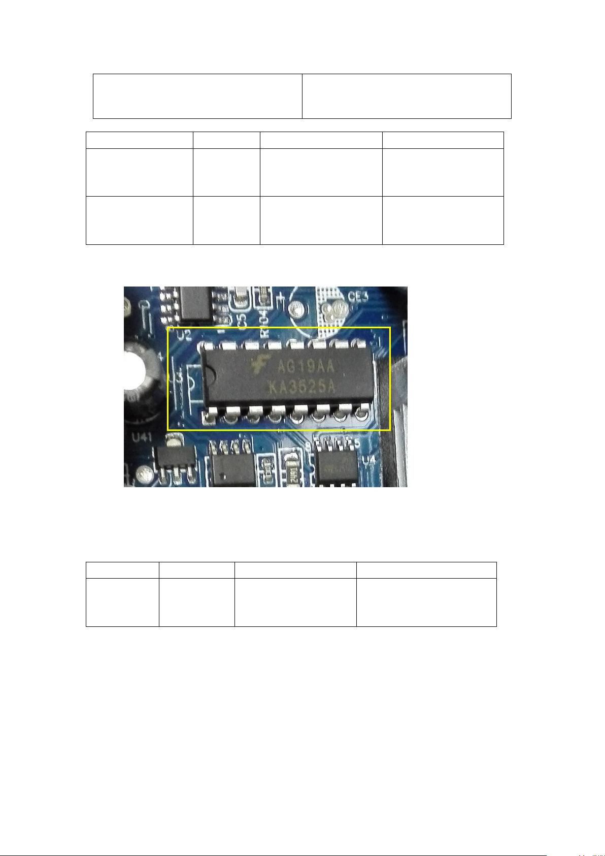
U3: 160-00006-00 ( Plug-In : IC LINEAR FAIRCHILD/KA3525A)
Positioning
Attribute
Reference Value
Failure Status
U3
Diode
Pin11-Pin12:5.4M
Pin13-Pin12: 60K
Pin14-Pin12: 5.4M
Short Circuit or Burnt
If unable to make sure which components, we would like to suggest to replace them all.
Pin16
Pin9
Pin8
Pin1
SUNRAELE
Service Manual
SUNRAELE Off-Grid Inv P 2-3kW
 Loading...