

Page 1

SUNPUMPS SPB-SERIES
PISTON PUMP SERVICE MANUAL
Caution: Piston pumps are positive displacement pumps. Therefore, a properly
designed pressure RELIEF OR SAFETY VALVE MUST BE INSTALLED in the
discharge piping. Failure to install such a relief mechanism could result in personal
injury or damage to the pump or system. SunPumps does not assume any liability or
responsibility for the operation of a customer’s high-pressure system.
INSTALLATION AND START-UP INFORMATION
Optimum performance of the pump is dependent upon the entire fluid system and will be
obtained only with the proper selection, installation of plumbing and operation of the
pump.
LUBRICATION: Fill crankcase with special hydraulic oil per pump specifications.
DO NOT RUN PUMP WITHOUT OIL IN CRANKCASE. Change initial fill after 50
hours running period. Thereafter, change oil every three months or at 500 hour
intervals.
PUMP ROTATION: Pump was designed for forward rotation to allow optimum
lubrication of the crosshead area. Reverse rotation is acceptable if the crankcase oil level
is increased slightly above center dot to assure adequate lubrication.
To minimize piping stress, use appropriate flexible hose to inlet and discharge ports.
Use the correct belt; make sure pulleys are aligned. Excessive belt tension may be
harmful to the bearings. Hand rotate pump before starting to be certain shaft and
bearings are free moving.
LOCATION: If the pump is used in extremely dirty or humid conditions, it is
recommended pump be enclosed. Do not store or operate in excessively high
temperature areas or without proper ventilation.
INLET CONDITIONS: Refer to complete Inlet Condition Check-List in this
manual before starting system. DO NOT STARVE THE PUMP OR RUN DRY.
DISCHARGE PLUMBING: OPEN ALL VALVES BEFORE STARTING
SYSTEM to avoid deadhead overpressure condition and severe damage to the pump or
system.
Install a Pulsation Dampening device mounted directly to the discharge line. Optimum
precharge should be calibrated at 30-50% of the operating system.
A reliable Pressure Gauge should be installed near the discharge outlet of the highpressure manifold.
The pump is rated for a maximum pressure; this is the pressure, which would be read at
the discharge manifold of the pump.
Page 2
An Unloader or Relief Valve must be installed to prevent over pressurizing the
pump in the event the discharge or downstream plumbing becomes plugged or is turned
off. Severe damage to the pump will result if this condition occurs without a relief valve
in the line. CAUTION: Failure to install such a safety valve will void the warranty
on the pump. Discharge regulating devices should be at minimum pressure setting
at start-up. On systems over 2000-PSI SECONDARY PROTECTION is recommended
by installing a pop-off valve, safety valve or rupture disc. START SYSTEM WITH ALL
VALVES OPEN OR IN THE LOW PRESSURE SETTING.
Use PTFE liquid (sparingly) or tape to connect accessories or plumbing. Exercise
caution not to wrap tape beyond the last thread to avoid tape from becoming lodged in the
pump or accessories. This condition will cause a malfunction of the pump or system.
STORING: For extended storing or between use in cold climates, drain all pumped
fluids from the pump and flush with antifreeze solution to prevent freezing and
damage to the pump. DO NOT RUN PUMP WITH FROZEN FLUID.
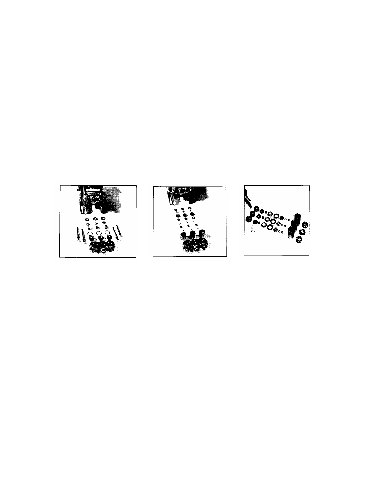
SERVICING THE VALVE ASSEMBLIES
DISASSEMBLY
1. Remove the fasteners securing the discharge manifold to the crankcase of the pump.
2. Support the discharge manifold and tap from the backside with soft mallet. Gradually
work free from cylinders.
3. Valve assemblies will remain in the manifold. Pump models with the o-ring groove
on the outside of the valve seat require the assistance of a Valve Seat Removal
Tool to remove the valve seat. The valve, spring and retainer will then fall out
when the manifold is inverted.
Pump models without the o-ring groove on the outside of the valve seat permit the seat,
valve,
spring and retainer all to fall out when manifold is inverted.
REASSEMBLY
1. Examine Retainer for wear and replace as needed. Place Retainer in manifold
chamber with nylon tab down.
2. Examine springs for fatigue and replace as needed. Insert spring into center of
Page 3
retainer.
3. Inspect the Valves for wear, ridges or pitting and replace as needed.
Note: Seating side of Flat Valves may be lapped on flat surface using 240 grit paper.
Quiet Valves due to their shape must be replaced. Insert valve over spring with
dimpled side up.
Note: Do not mix Quiet Valve and Flat Valve Assemblies.
4. Examine Valve Seats for wear, pitting or grooves. Lap the Flat Valve Seats with 240
grit paper or replace if evidence of excessive wear. Quiet Valve Seats must be
replaced if worn. Install seats with dishside down.
5. Examine o-rings and back-up rings on the Valve Seat if used and replace if worn.
Always lubricate o-rings for ease of installation and to avoid damage.
Note: First install o-ring in groove on seat towards seating surface, then back-up ring.
Note: Models without outer groove on seat require the o-ring to be placed on lip of
retainer.
6. Lubricate o-rings on exposed cylinder. Exercise caution when slipping manifold over
Cylinders to avoid damaging cylinder o-rings. Completely press manifold over
cylinders.
7. Replace fasteners and torque per chart.
Note: Replace all original shims if used. When new manifold is used reshim pump.
When starting the pump, check to see that there is no cylinder motion, as this will
cause premature failure of the cylinder o-rings. Center cylinder motion indicates
improper shimming.
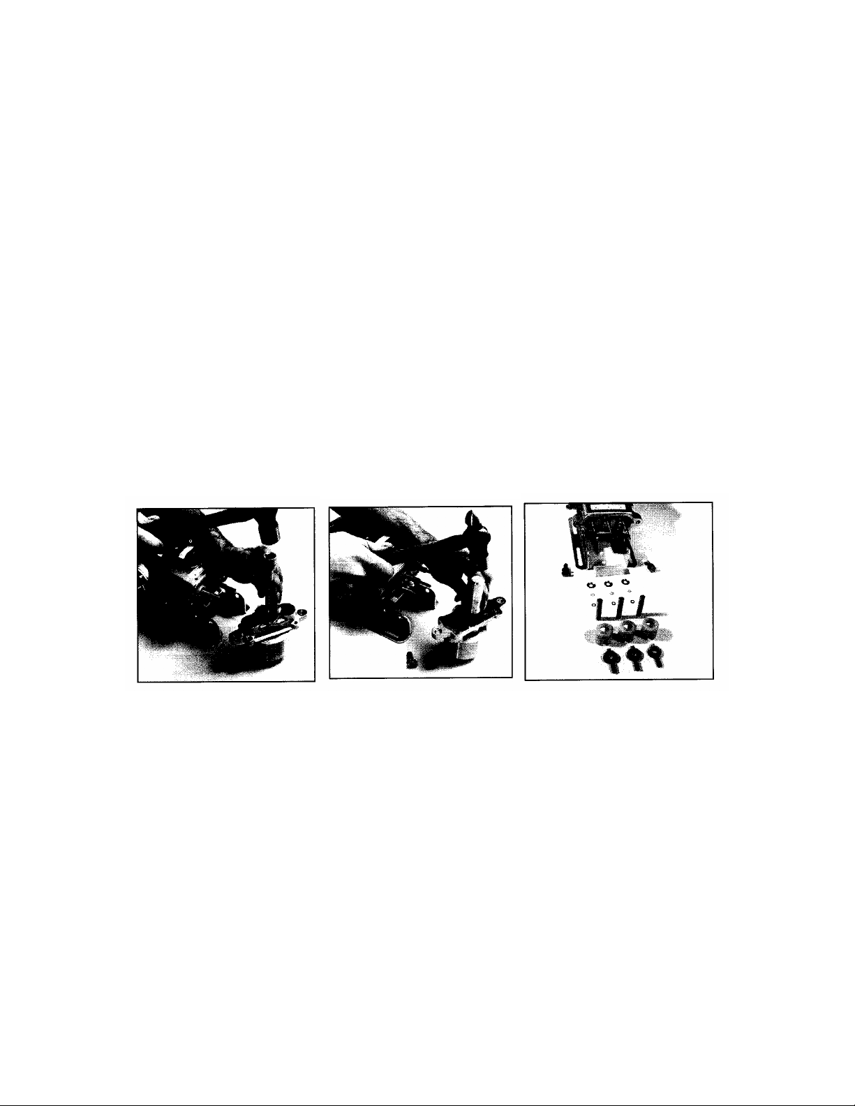
SERVICING THE PUMPING SECTION
STANDARD PISTON PUMP
DISASSEMBLY:
1. Remove the discharge manifold as described above.
2. Grasp cylinders by hand and with an up and down motion, pull cylinders from inlet
manifold.
3. Remove cotterpin, nut and washer from piston rod.
4. Next remove retainer, spacer, piston-cup assembly and inlet valve.
REASSEMBLY:
1. Examine inlet valve surface for pitting, scale or grooves. Reverse valves and sand
inlet side of valve using 240 grit paper for clean surface or replace if evidence of
excessive wear. Slip onto rod.
2. Examine Piston seating surface and lightly sand on flat surface using 240 grit paper.
Page 4

If extreme pitting or sharp edges, replace piston.
3. Examine cup for wear, cracking, tearing or separation from the piston. If worn
replace and lubricate before installing on piston.
Note cup installation: Wipe cup inserter with oil. Slip back-up ring (when used)
onto piston. Push cup over inserter and square with all surfaces. Faulty cup
installation causes premature cup failure. Some models use a one-piece piston
assembly. The cup does not separate from the piston. Replace entire assembly.
Lubricate piston assembly and slip piston-cup assembly onto piston rod with lid
facing discharge.
4. Next replace Piston Spacer and Retainer on rod.
5. Replace washer; thread on nut and torque per chart.
Note: Always replace with new stainless steel cotterpin and turn ends under.
6. Examine cylinder walls for scoring or etching which causes premature wear of cups
and replace as needed.
7. Lubricate cylinder and replace o-rings and/or back-ups rings if worn or damaged.
Back-up rings go to low pressure side of the o-rings. Carefully slip cylinder
over rod ends and push into inlet manifold with back-up ring to the discharge,
stroke marking on the inside of cylinder to the crankcase.
8. Position discharge manifold onto pump as described, replace fasteners and torque
per specifications chart.
SLEEVED-TYPE PISTON MODELS
DISASSEMBLY
1. After removing the discharge manifold, slip cylinders off piston rods. It is best
to leave the cylinder adapters and springs in the inlet manifold as they may score
the sleeved-type pistons when removed. The V-packings will remain in the cylinders.
2. Press worn V-packings from cylinders.
3. Remove cotter pins, slotted nuts, washers and piston retainers. Pull sleeved-type
pistons from each piston rod. Next slip sleeved-type spacer and inlet valve from each
piston rod.
4. Lubricate and install new o-rings on cylinders and adapters.
5. Inspect inlet valve surfaces. If inlet valves are worn, lap with 240 grit paper or
replace if evidence of excessive damage. If sleeved-type piston inlet surface is worn
or the outer diameter is scored, replace it.
REASSEMBLY
1. First install inlet valve then sleeved-type piston onto piston rod with the lapped end
toward the inlet valve.
2. Next install the sleeved-type spacer.
3. Then install new V-packings in the cylinder in the following order:
a. Install all parts in one cylinder, and then move to the next cylinder.
b. Rotate crankshaft to extend one piston rod completely forward.
c. Lubricate V-packings and cylinder I.D. and place O-ring end of cylinder on
work surface.
d. Install into cylinder Female Packing Spacer, black Female Adapter, V-packings,
nylon Male Adapter and Male Packing Spacer with “V” side down.
e. Install spring in outer end of cylinder and slip cylinder assembly over piston rod
end. Press cylinder into manifold chamber. The spring in the cylinder will be in
Page 5

your palm as the cylinder assembly is installed. Use the spring to hold parts in
cylinder as it is slid over piston rod.
4. Remove spring from cylinder, install retainer, conical washer, slotted nut and torque
per chart.
5. Install new cotter pin and bend ends back.
6. Replace spring in cylinder.
7. Lubricate inlet and discharge ends of adapter and install back-up rings first, then orings onto adapter. Lubricate O.D. of small diameter inlet end of adapter and press
into cylinder.
8. Rotate crankshaft to extend new piston rod. Proceed as above with second and third
cylinders. Proceed with standard Piston Pump Servicing.
SERVICING SLEEVES AND SEALS
DISASSEMBLY
1. Remove discharge manifold and piston assemblies as described.
2. Remove inlet manifold containing seals.
3. Grasp sleeves and with a pulling and twisting motion remove the sleeve from the
piston rod.
Note: Grasp sleeve with pliers only if replacing worn sleeves, as the procedure will
mar the sleeves.
4. Next remove seal retainer.
5. Remove and examine o-rings and/or back-up rings on piston rod for wear and
replace as needed.
REASSEMBLY
1. Visually inspect that Barrier-Slinger is in position.
2. Lubricate new o-rings and/or back-up rings and slip onto piston rod. Install the first
o-ring (A) in the groove on the piston rod. Next position back-up ring (B) against the
stepped shoulder. Then install the second o-ring (C). Exercise caution as you slip the
o-ring over the thread end of the piston rod.
3. Examine sleeves for scoring or etching and replace. Immerse sleeves (D) in oil and
carefully twist and push sleeve onto rod with machined counter bore end first
(E).
4. Next install seal retainers. If wicks are used, replace wicks, thoroughly saturate with
oil, place in seal retainer and install retainer.
5. Place inlet manifold on pair of clearance blocks with crankcase side down and drive
out old seals.
6. Invert inlet manifold with crankcase side up and install new seals. Lubricate O.D. of
seal and install Prrrrm-A-Lube seal with garter spring down. If using blue dot seal,
install blue dot seal facing up.
7. Slip lubricated seal inserters onto piston rod ends, position inlet manifold onto pump
and remove seal inserters. Some models secure inlet manifold to crankcase. Replace
fasteners and torque per specification chart.
8. Reassemble piston assemblies and discharge manifold as described.
Page 6

9. Replace original quantity of shims on each stud before replacing discharge manifold.
SERVICING CRANKCASE SECTION
1. While inlet manifold sleeves and seal retainers are removed, examine crankcase seals
for wear.
2. Check oil for proper level and for evidence of water in oil or other contaminants.
3. Rotate crankshaft by hand to feel for smooth bearing movement.
4. Examine crankshaft oil seal externally for drying, cracking or leaking.
5. Consult SunPumps if crankcase service is required.
PREVENTATIVE MAINTENANCE CHECK-LIST
Check Daily Weekly 50 hrs 500 hrs 1500
hrs
Clean Filters X
Oil Level/Quality X
Oil Leaks X
Water Leaks X
Belt, Pulleys X
Plumbing X
Initial Oil Change X
Oil Change X
Seal Change X
Valve Change X
Accessories X
If other than CAT PUMP Oil used, change cycle should be every 300 hours.
Each system’s maintenance cycle will be exclusive. If system performance decreases,
check immediately. If no wear at 1500 hours, check again at 2000 hours and each 500
hours until wear is observed.
Remember to service the regulator/unloader at each seal servicing and check all system
accessories and connections before resuming operation.
INLET CONDITION CHECK-LIST
REVIEW BEFORE START-UP
Inadequate inlet conditions can cause serious malfunctions in the best designed pump.
Surprisingly, the simplest of things can cause the most severe problems or go unnoticed
to the unfamiliar or untrained eye. REVIEW THIS CHECK-LIST BEOFRE
OPERATION OF ANY SYSTEM. Remember, no two systems are alike, so there can be
no ONE best way to set up a system. All factors must be carefully considered.
Page 7

INLET SUPPLY should be adequate to accommodate the maximum flow being
delivered by the pump.
Open inlet shut-off valve and turn on water supply to avoid cavitating pump.
DO NOT RUN PUMP DRY Starting a pump dry will damage the piston cups
immediately. If there is a possibility of the pump ever running dry, low water level
controls should be used.
When using an inlet supply reservoir, size it to provide adequate fluid to accommodate
the maximum output of the pump, generally a minimum of 6-10 times the GPM
(however, a combinations of system factors can change this requirement); provide
adequate baffling in the tank to eliminate air bubbles and turbulence; install diffusers on
all return lines to the tank.
INLET LINE SIZE should be adequate to avoid starving the pump.
Line size must be a minimum of one size larger than the pump inlet fitting.
Avoid thick walled fittings, tees, 90 degree elbows or valves in the inlet line of the
pump to reduce the risk of flow restriction and cavitation.
The line MUST be a FLEXIBLE hose, NOT a rigid pipe, and reinforced on SUCTION
systems to avoid collapsing.
The simpler the inlet plumbing the less the potential for problems. Keep the length
to a minimum, the number of elbows and joints to a minimum (ideally no elbows) and
the inlet accessories to a minimum
. Use pipe sealant to assure air-tight, positive sealing pipe joints.
After prolonged storage, pump should be purged of air to facilitate priming.
Disconnect any discharge port and allow fluid to pass through pump.
Page 8

HOSE FRICTION LOSS
Pressure drop in PSI per 100 ft of hose
Water with typical water flow rates.
Flow Hose Inside Diameters, Inches
Gal/Min. ¼ 5/16 3/8 ½ 5/8 ¾ 1”
0.5 16 5 2
1.0 54 20 7 2
2.0 180 60 25 6 2
3.0 380 120 50 13 4 2
4.0 220 90 24 7 3
5.0 320 130 34 10 4
6.0 220 52 16 7 1
8.0 300 80 25 10 2
10 450 120 38 14 3
15 900 250 80 30 7
20 1600 400 121 50 12
25 650 200 76 19
30 250 96 24
40 410 162 42
50 600 235 62
60 370 93
*At a fixed rate with a given size hose, the pressure drop across a given hose length will be
directly proportional. A 50 ft hose will exhibit one-half the pressure drop of a 100 ft hose.
Above values shown are valid at all pressure levels.
WATER LINE PRESSURE LOSS
Pressure Drop in PSI Per 100 Feet
Water Steel Pipe-Nominal Dia. Brass Pipe-Nominal Dia Copper Tubing O.D.
Type L
GPM ¼ 3/8 ½ ¾ 1 1 ¼ 1 ½ ¼ 3/8 ½ ¾ 1 1 ¼ 1 ½ ¼ 3/8 ½ 5/8 ¾
7/8
1 8.5 1.9 6.0 1.6 120 13 2.9 1.0
2 30 7.0 2.1 20 5.6 1.8 400 45 10 3.4 1.3
3 60 14 4.5 1.1 40 11 3.6 94 20 6.7 2.6
5 150 36 12 2.8 100 28 9.0 2.2 230 50 17 6.1
3.0
8 330 86 28 6.7 1.9 220 62 21 5.2 1.6 500 120 40 15
6.5
10 520 130 43 10 3.0 320 90 30 7.8 2.4 180 56 22
10
15 270 90 21 6.2 1.6 190 62 16 5.0 1.5 120 44
20
25 670 240 56 16 4.2 2.0 470 150 40 12 3.8 1.7 330 110
50
40 66 17 8.0 39 11 5.0 550 200
88
60 37 17 23 11
80 52 29 40 19
100 210 107 48 61 28
Page 9

RESISTANCE OF VALVES AND FITTINGS
Nominal Equivalent Length of Standard Pipe in Feet
Pipe Inside 180 Tee Tee
Size Diameter Gate Globe Angle 45 90 Close Thru
Thru
Inches Inches Valve Valve Valve Elbow Elbow Ret Run
Branch
½ 0.622 0.41 18.5 9.3 0.78 1.67 3.71 0.93
3.33
¾ 0.824 0.54 24.5 12.3 1.03 2.21 4.90 1.23
4.41
1 1.049 0.69 31.2 15.6 1.31 2.81 6.25 1.56
5.62
1 ¼ 1.380 0.90 41.0 20.5 1.73 3.70 8.22 2.06
7.40
1 ½ 1.610 1.05 48.0 24.0 2.15 4.31 9.59 2.40
8.63
2 2.067 1.35 61.5 30.8 2.59 5.55 12.30 3.08
11.60
2 ½ 2.469 1.62 73.5 36.8 3.09 6.61 14.70 3.68
13.20
3 3.068 2.01 91.5 45.8 3.84 8.23 18.20 4.57
16.40
4 4.026 2.64 120.0 60.0 5.03 10.80 23.90 6.00
21.60
Arriving at a total line pressure loss, consideration should then be given to pressure
loss created by values, fittings and elevation of lines.
If a sufficient number of values and fittings are incorporated in the system to
materially affect the total line loss, add to the total line length, the equivalent leng th
of line of each value or fitting.
Page 10

DIAGNOSIS AND MAINTENANCE
PROBLEM PROBABLE CAUSE SOLUTION_____________
Pulsation *Faulty Pulsation Dampener Check pre-charge. If low, recharge or install
a new one.
Low Pressure *Belt slippage Tighten or replace. Use correct type/length.
*Air leak in inlet plumbing Disassemble, reseal and reassemble
*Pressure gauge inoperative or not Check with new gauge; replace worn
registering accurately or damaged gauge.
*Relief valve stuck, partially plugged Clean and adjust relief valve; check for
or improperly adjusted; valve seat worn worn or dirty valve seats. Repair with
Valve Kit.
*Inlet suction strainer clogged or improper size Clean. Use adequate size. Check frequently
*Worn Piston Assy. Abrasives in pumped Install proper filter. Suction at inlet manifold
fluid or severe cavitation. Inadequate water must be limited to lifting less than 20’ of water
supply or –8.5 PSI vacuum.
*Fouled or dirty inlet or discharge valves Clean inlet and discharge valve assemblies
*Worn inlet or discharge valves Replace worn valves, valve seats.
*Leaky discharge hose Replace discharge hose and check for air
tight connections.
* Worn nozzle Replace nozzle to proper size
Pump runs extremely *Restricted inlet or air entering the inlet Proper size inlet plumbing; check for air
rough, pressure very low plumbing tight seal.
*Damaged cup or stuck inlet or discharge Replace worn cups or valves; clean out
valve foreign material.
*Worn inlet seals allowing air into system Install new inlet manifold seals and possibly
or leaking fluid sleeves.
*Stressful inlet condition Pressurize inlet
Cylinder o-ring blown next *Pressure in excess of rated PSI or distorted Check for plugged nozzle, closed valves or
to discharge manifold manifold from freezing damage improperly adjusted by-pass valve and replace
defective manifold or o-ring. PROTECT FROM
FREEZING.
Leakage at the cylinder *Loose cylinders. Cylinder motion caused by Remove spacer shims on manifold studs. Do
o-rings at the discharge improper shimming of the discharge not remove too many shims or the ears of the
manifold and black manifold. manifold will be bowed when the manifold is
powdery substance in the retightened, causing looseness in the center of
area of the o-ring. the cylinder.
Water leakage from under *Worn inlet manifold seals. Leaking sleeve Install new o-rings as required. Replace scored
the inlet manifold o-ring. sleeves.
Oil leak between crankcase *Worn crankcase piston rod seals. Replace crankcase piston rod seals.
and pumping section *Excess oil from wicks Reduce quantity of oil per oiling.
Oil leaking in the area of *Worn crankshaft seal or improperly Remove oil seal retainer and replace damaged
crankshaft installed oil seal retaining package gasket and/or seals
*Bad bearing Replace bearing
Excessive play in the end *Worn main ball bearing from excessive Replace bearing. Properly tension belt. Use
of the crankshaft pulley tension on the drive belt correct type and length.
Water in crankcase *May be caused by humid air condensing Change oil every 3 months or 500 hour intervals
into water inside the crankcase using special CAT PUMP non detergent
HYDRAULIC OIL
*Leakage of manifold inlet seals and/or Replace seals, sleeves and o-rings
Oil leaking from side of *Worn crankshaft seals Replace seals
crankcase
Oil leaking at the rear *Damaged or improperly installed oil Replace oil gauge, cover o-ring, or drain
portion of the crankcase gauge or worn crankcase rear cover plug o-ring as needed.
piston rod sleeve o-ring
Page 11

o-ring, or drain plug o-ring
Oil leakage from drain plug *Loose drain plug or worn drain plug o-ring Tighten drain plug or replace o-ring
Loud knocking noise in *Pulley loose on crankshaft Check key and tighten set screw
the pump *Broken or worn bearing Replace bearing
Check alignment and belt position
Frequent or premature *Scored rods or sleeves Replace rods and sleeves
failure of the inlet manifold *Over pressure to inlet manifold Reduce inlet pressure
seals *Stressful inlet conditions Pressurize inlet
Short cup life *Abrasive material in fluid being pumped Install proper filtration on pump inlet plumbing
*Excessive pressure and/or temperature Check discharge pressure, fluid temperature, or
of fluid being pumped control valve by-pass.
*Running pump dry Do not run pump without water.
*Front edge of piston sharp. Replace with new piston.
*Chrome plating of cylinders damaged Install new cups and cylinders
causing excessive wear of cups. May be
caused by pumping acid solution
*Short life on cups on cylinders Stressful inlet conditions
Strong surging at the inlet *Foreign particles in the inlet or Check for smooth mating surfaces or inlet
and low pressure on the discharge valve or worn inlet and/or inlet valves and discharge valve sealts.
discharge side discharge valves F.V. and inlet valves may be lapped
on a very fine oil stone; Q.V. parts must
be replaced.
 Loading...