

Page 1
SDS-D SERIES PUMP REBUILD INSTRUCTIONS
1 ½”
DISASSEMBLY
1. Remove cable guard screws (Item 21).
2. Remove the 3/8" NC set screw (Item 19) using 3/16" hex wrench. WARNING: PUMP
HOUSING MAY BE UNDER HIGH PRESSURE. USE EXTREME CAUTION IN
REMOVING THE END CAP PLUG AND END CAP SCREWS. We recommend
loosening the discharge head bolts first and pull the discharge head up slightly to relieve
any pressure that may be inside.
3. Remove the two socket head screws (Item 2) from end cap assembly (Item 17) using a
5/32" hex wrench.
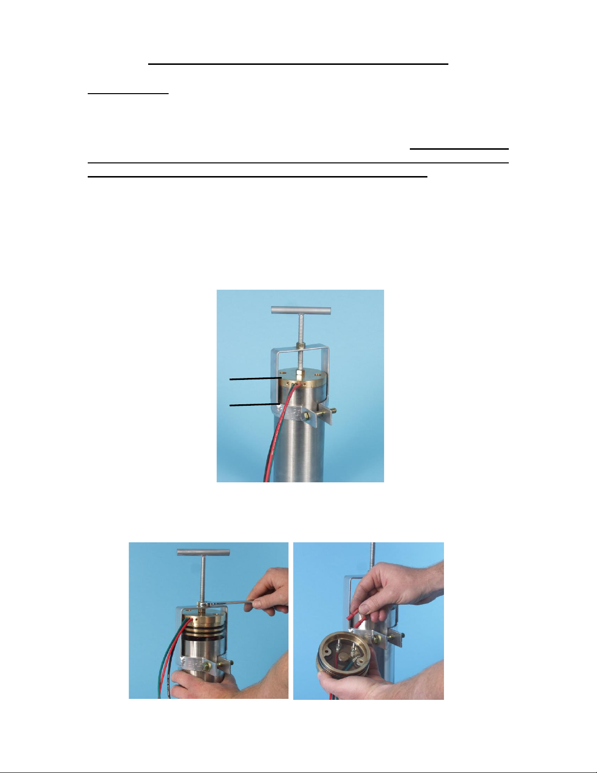
4. Clamp the pump in the puller and screw the threaded mandrel in the end cap.
5. Pull the end cap out of the stainless housing. As the end cap (Item 17) comes out
disconnect the two motor wires plugged into the cap.
Page 2
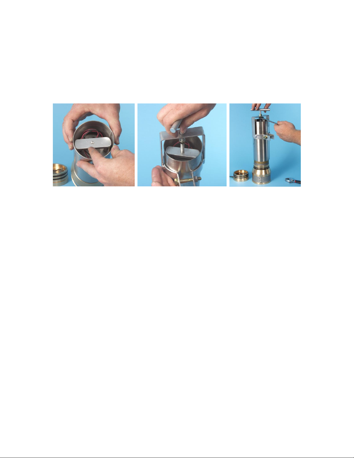
6. With the end cap removed from the housing, place the push plate across the two motor
nuts with the center hole facing up. Reinstall the puller and place the end of the threaded
rod inside the hole of the push plate.
With a 9/16” wrench, turn the bottom nut counter-clockwise to push the pump assembly
out of the stainless steel housing.
7. Remove the four socket head screws (Item 2) from the discharge head using a 5/32"
hex wrench.
8. Remove the bypass valves and springs (Items 8 & 9), suction screen (Item 5), check
valve body (Item 7) and check valve O-ring (Item 6) from the discharge head. Note:
Check valve removal may require a light tap with a blunt tool through the discharge
opening.
9. Remove the two motor adapter screws (Items 10) using a 5/32" hex wrench. Remove
the set screw from the cam assembly using a long 1/8" hex wrench. This wrench must be
inserted through the slot in the side of the motor adapter (Item 14). Before inserting the
wrench, visually align the set screw with the hole by turning the motor adapter while
holding the motor.
10. Pull the motor adapter and cam assembly away from the motor, remove the two piston
screws (Item 23), and then the cam assembly (Item 15).
11. Discard outer pistons (Item 13), O-rings (Items 18), diaphragm (Item 12), check valve
(Item 7), and O-ring (Item 6).
12. Clean and inspect all remaining parts and make sure that the electrical studs
protruding from the epoxy in the end cap are in good condition and the epoxy is still hard.
Page 3

SDS PUMP REBUILD INSTRUCTIONS
ASSEMBLY
1. Set the two pistons (Items 11) flat side down on the pump assembly plate, positioning
the two holes over locating studs.
2. Place the diaphragm (Item 12), with the offsets up, over the pistons locating the piston
shafts through the two holes.
3. Slip the outer pistons (Item 13) over the piston shafts with the radius side toward the
diaphragm.
4. Set the motor adapter (Item 14) face down over the diaphragm assembly allowing the
piston to protrude through the two holes being careful not to nick or cut the diaphragm.
5. Put the set screw into the cam and insert the cam assembly (Item 15) over the piston
shaft making sure the piston shafts fit into the cam plate holes.
6. Insert the two washers (Item 3) and two piston screws (Item 23) through the cam
assembly, and tighten with a 5/32" hex wrench to 60 inch lbs. of torque. (Be careful not to
allow the pistons to slip off the locating studs while tightening the screws.) Each screw
should be tightened a little at a time alternating between each side. This will pull both
pistons into alignment before either piston clamps the diaphragm.
7. Place the motor on the assembly board with the shaft up. Turn the motor shafts until
the flat side faces you.
8. Coat the inside of the cam hole and the outside of the motor shaft with silver anti-seize
compound.
9. Insert a long 1/8" hex wrench through the hole in the motor adapter and into the cam
set screw.
10. Slip the cam assembly over the motor shaft aligning the set screw to the center of the
flat on the shaft. As the cam assembly is inserted over the motor shaft tighten the set
screw until it lightly touches the motor shaft and then back it off 1/8 turn. Continue
installing the cam assembly until the motor adapter butts up to the motor. Then push on
the pistons until the cam assembly bottoms on the motor shaft. While holding the piston
down firmly, tighten the set screw.
11. With the motor assembly still on the board, gently lift the diaphragm up on each end
and insert one stainless washer (Item 3) in each motor adapter hole.
Page 4

12. Lightly coat the two 10-32 X 2" motor adapter screws (Item 10) with RTV silicon
and then insert them into the motor adapter holes. Rotate the motor adaptor slowly until
screws "drop" into place. Tighten the screws while alternating between the two, to 45
inch lbs. of torque.
13. Lay the discharge head (Item 4) top side down on a flat surface and install the suction
screen (Item 5) with the welded seam placed between the two cable guard screw holes.
14. Install the check valve O-ring (Item 6) and check valve (Item 7) into the discharge
head. (Make sure check valve assembly is flush with discharge head.) Turn the discharge
head over and insert the four washers (Items 3) and the 10-32 X 1 1/2" stainless screws
(Items 2) and in the 4 countersunk holes. Before inserting the screws apply a small
amount of anti-size compound to the threads.
15. Install the two relief valves (Items 8) into the two springs (Items 9) until seated. With
the motor and motor adapter still on the assembly board insert the two relief valve spring
assemblies over the small studs on the diaphragm with the relief valves pointing up.
16. With the motor assembly still held in a vertical position install the discharge head on
the motor adapter while carefully guiding the relief valves into the holes in the check
valve assembly. Make sure the relief valve springs stay on the small studs and the relief
valve is seated in the check valve assembly.
17. While holding the discharge head in position tighten the four screws a little at a time,
jumping to opposite sides, to 45 inch lbs. of torque.
18. Set the pump with the discharge end facing down on a flat table.
19. Install the two O-rings (Item 18) onto the motor adapter and lightly lubricate with a
non out-gassing food grade grease or petroleum jelly.
20. Lightly grease the inside of both ends of the stainless housing about one inch deep
and slip it over the pump assembly, with the longer inside bore down, until it rests on the
O-rings. With a small block of wood or other soft flat object push the housing down over
the O-rings until it touches the lip on the motor adapter.
21. Screw a 10-32 X 3" stud (Not Provided) into one of the coupling nuts on the back side
of the motor. This is used as a guide when installing the end cap assembly.
22. Install the two O-rings on the end cap assembly (Item 17) and lightly lubricate the Orings.
23. Connect the motor leads onto the electrical studs on the inside of the end cap. (Make
sure the positive red wire lead connects to the red wire side and the black to the black
wire side.) Before seating end cap in housing, be sure that the terminals on the wires are
tight on the end cap electrical studs. Slide the end cap over the guide stud, making sure
that the motor lead wires are not pinched between the end cap coupling nuts. Make sure
the cable guard screw holes are on the same side as the screw holes in the discharge head.
Page 5

24. With a small block of wood push the end cap down inside the housing until it butts up
against the cap lip.
25. Remove the guide stud, insert the two 10-32 X 1 1/2" end cap screws (Items 2),
washers (Items 3) and new O-rings (Items 22). Apply a small amount of non-outgassing
silicone sealant around the O-ring. CAUTION: DO NOT USE ANY SILICONE
SEALANT THAT HAS AN ODOR. (DOW CORNING 3145 RTV
ADHESIVE/SEALANT IS RECOMMENDED). Tighten the two screws to 35 inch lbs.
of torque.
26. Install the end cap plug and tighten with a 3/16" hex wrench. A non out-gassing antiseize should be used on the threads.
27. Install the cable guard over the motor lead using the four screws (Items 21).
28. The pump is now ready to install.
Page 6

 Loading...