

SUNPRO FZ88R, SST802R Installation Instructions Manual

®
STEERING COLUMN MOUNTING INSTRUMENT PANEL MOUNTING PANEL LAYOUT
2-1/4”
9
8
3
5
4
7
1
2
6
TACH
ITEM NO . DESC RIP TION
QTY.
1 1
2 1
3 1
4 1
5 1
6 2
7 2
8 1
9 1
CUP
FEMALE NUT
MALE NUT
M O U N T I N G BRACKET
COLUMN B R A C K E T
#8 LOCK W ASHER
#8-32 ACORN NUT
ADJUSTABLE CLAMP
RUBBER S TRIP
SUNPRO
3-3/8" TACHOMETERS
SST802R, FZ88R
INSTALLATION INSTRUCTIONS
GENERAL INFORMATION
These tachometers are designed for 12-volt negative
(-) ground 4-cycle engines. As sold they are compatible
with most distributor and distributorless ignition systems.
The CP7560 Tach Signal adapter is required to connect
the tachometer to Coil On Plug ignition systems and to
diesel engines with electronic injection.
HARDWARE KIT CONTENTS
Dash Mount Bracket...................................................1 ea
Column Mount Bracket...............................................1 ea
Chrome Cup................................................................1 ea
Adjustable Clamp........................................................1 ea
Installation Kit .............................................................1 ea
CAUTION
Please read this instruction manual and review the
installation procedures carefully before attempting the
installation of your tachometer.
SAFETY GUIDELINES
To prevent accidents that could result in serious injury and/
or damage to your vehicle or tachometer, carefully follow
these safety rules and test procedures.
Wear safety goggles when working on your vehicle.
•
A l w a y s o p e r a t e v e h i c l e i n a
•
well-ventilated area. If vehicle is in an enclosed area,
exhaust should be routed directly to the outside via
leakproof exhaust hose.
Make sure that your vehicle is in Park or Neutral, and
•
that the parking brake is rmly set.
Avoid contact with hot surfaces such as exhaust
•
manifolds and pipes, mufers (catalytic converters),
radiator and hoses.
FUNCTIONAL QUICK CHECK
It is suggested that the tachometer be electrically
connected to the vehicle, (using alligator clip leads or
other suitable means) following the steps below, and an
electrical functional check of the tachometer be made,
prior to making a permanent installation.
Start the vehicle’s engine. Conrm the operation of the
tachometer. Disconnect the tachometer.
INSTALLING MOUNT BR ACKET
Your tachometer is designed to be mounted on any
at or curved surface, or on the steering column
using the clamp kit.
Steering Column Mounting
1. Assemble steering column bracket (5) and cup (1)
using male nut (3) and female nut (2). Tighten male
nut only enough to still allow cup to be positioned to
proper angle.
2. Wrap rubber strip (9) around steering column.
3. Place assembled cup and column bracket on rubber
strip and secure to steering column with adjustable
clamp (8).
Instrument Panel Mounting
1. Select best possible mounting location for good visibility from a normal driving position.
2. Mounting bracket (4) can be used for a marking or
drill template.
3. Drill two 3/16” holes for #8 screws, lock washer and
nuts or two 5/32” holes for #8 self-tapping screws.
This picture is not to scale!
FULL ON E (1) YE AR WARRAN TY
Sunpro, 15825 Ind ustrial Parkway, Clevel and, Ohio 44135, warrants to the
user that this unit will be f ree f rom d efects in m aterials and workmanship for
a period of one (1) year fro m the date of origin al purchase.
Any unit that fails wit hin this period will be repaired or replaced at Sunpro’s
option and wi thout charge when returned to the Factory. Sunpro re quests
that a co py of the origina l, dated sales re ceipt be return ed with the unit t o
determine if the warrant y period is still in effec t.
This warranty does not a pply to damages caused by acciden t, alter ations, or
improp er or unreasona ble use. Expendable items, such as bat teries, fuses,
lamp bulb s, ash tubes are al so excluded from t his warranty.
Sunpro DISCLAIMS ANY LIABILITY FOR INCIDENTAL OR CONSEQUENTIAL DAMAG ES FOR BRE ACH O F AN Y WRI TTEN WARRANT Y ON THE
UNIT. Some s tates do not allow the disc laimer of liabil ity for incidental or
consequentia l d amages, so the above disclai mer may or may not apply to
you. T his warrant y gives speci c le gal ri ghts, a nd you may also have rights ,
which vary from state to st ate.
SWITCHED
+12V
SEE SIGNAL
POST CONNECTION
WIRE
SPLICE
TO DIMMER
SWITCH
LIGHT
WIRE
LAMP INSTRUMENT
GROMMET
WIRE
TO GND
GND
WIRE
SIGNAL
WIRE
+12V
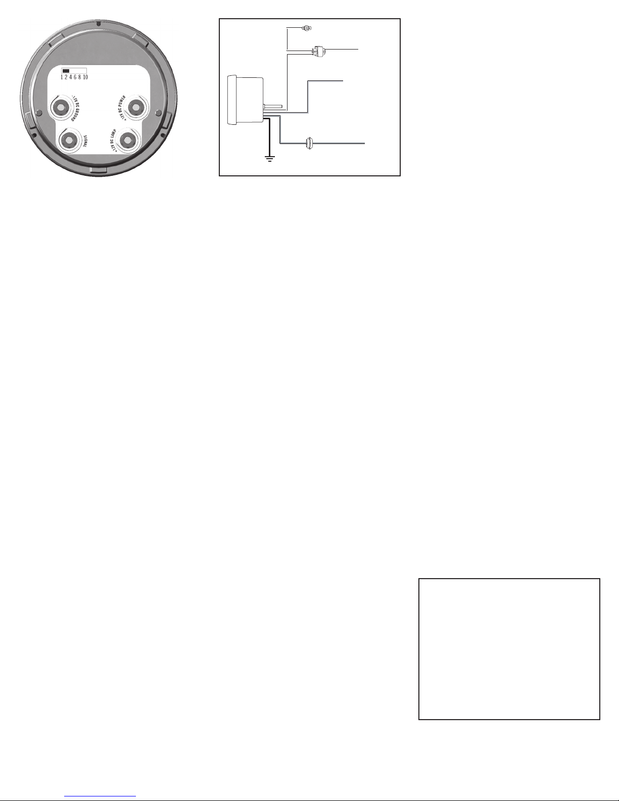
ELECTRICAL CONNECTIONS
CAUTION
For your own personal safety, and to prevent possible
damage to the electrical system of your vehicle during
the installation, disconnect the negative (-) battery cable.
Reconnect this cable after installation is complete. Do
not route wires along or against sharp edges, hot engine
surfaces, or near spark plug wires. If needed, drill a 3/8”
hole in the rewall for the grommet (included).
1. Attach wires to tachometer as required.
NOTE: Use # 18 or # 20 AWG stranded automotive
primary wire.
2. Thread wires through female nut (2), cup (1), bracket
(4 or 5) and male nut (3). Note: At this point, items 1,
2, 3 and 4 or 5 should have been preassembled.
3. Leave tachometer out of the cup for now.
SIGNAL POST CONNECTION AND CYLINDER
SELECTION
The Cylinder Selector Switch is located on the back of the
tachometer. The factory setting is 8-cylinders. Change
the setting if necessary.
DISTRIBUTOR EQUIPPED ENGINES
Connect the SIGNAL tachometer post to the negative
(-) side of the ignition coil. This terminal may be referred
to as the TACH, TACH TEST, DEC, or ECU terminal.
Set the Cylinder Selection switch on the back of the
tachometer to match the number of cylinders in the
engine.
DISTRIBUTORLESS IGNITION SYSTEM EQUIPPED
ENGINES WITH A TACHOMETER OUTPUT LEAD
Connect the SIGNAL tachometer post to the vehicle‘s
tachometer output lead.
Set the Cylinder Selection switch on the back of the
tachometer to match the number of cylinders in the
engine.
DISTRIBUTORLESS IGNITION SYSTEM EQUIPPED
ENGINES WITHOUT A TACHOMETER OUTPUT
LEAD
If your vehicle’s DIS ignition system does not have a
tachometer output lead but allows access to the driver
wires from the vehicle computer to the ignition module,
connect the SIGNAL tachometer post to one of the
driver wires.
Set the Cylinder Selection switch on the back of the
tachometer to the 2-cylinder position regardless of
the number of cylinders in the engine.
-12V DC GROUND, +12V DC POWER, AND 12V
DC LAMP POST CONNECTIONS
ALL VEHICLE SYSTEMS
1. Connect the post labeled -12V DC GROUND to the
negative (-) battery terminal, or a clean unpainted
chassis ground using a ring terminal or other suitable means.
2. Connect the post labeled
+12V DC POWER to any
vehicle harness wire which is energized with battery
voltage, ONLY when the ignition key is in the ON
(RUN) position, NOT OFF OR ACCESSORIES.
3. Connect the post labeled
12V DC LAMP to the
instrument panel lighting circuit that is controlled by
the instrument panel dimmer control.
Some vehicles (typically imported) wire the dimmer
control into the ground side of the instrument panel
lighting circuit, as opposed to the more conventional
“hot” or 12-volt side. In vehicles which use this circuit,
connect the 12V DC LAMP post to a circuit which is
energized by the headlamp switch.
INSTALLING TACHOMETER IN CUP
1. Place tachometer in cup. Gently pull wires out, so
they would not be jammed between the cup and
tachometer.
2. Secure tachometer in cup using #8 lock washers
(6) and #8-32 acorn nuts (7). Turn acorn nuts down
nger-tight and, with a wrench or nut driver, tighten an
additional 1/2 turn. DO NOT OVER TIGHTEN.
3. Position cup as desired and tighten male nut (3).
The 4, 6, 8, and 10-cylinder settings are most common
for all distributor equipped engines and Distributorless
Ignition Systems (DIS) with a tachometer output lead.
The 2-cylinder setting is designed for 2-cylinder engines and
DIS systems without a tachometer output lead that allow
access to the driver wires from the vehicle computer
to the ignition module.
The 1-cylinder setting is used with single cylinder engine
vehicles and in conjunction with the CP7560 Tach Signal
adapter.
The CP7560 Tach Signal Adapter (sold separately)
senses current pulses in the wire that supplies +12 volts
to the ignition coil primary windings or fuel injector and
converts the pulses to a signal that is understood by the
tachometer. The CP7560 Tach Signal Adapter is required
to connect the tachometer to Coil On Plug ignition systems
and to diesel engines with electronic injection.
MULTIPLE SPARK DISCHARGE IGNITION SYSTEM
EQUIPPED ENGINES
For Multiple Spark Discharge ignition systems, connect
the SIGNAL tachometer post only to the tachometer
output terminal on the ignition module. Do NOT connect
to the ignition coil.
Set the Cylinder Selection switch on the back of
the tachometer to match the number of cylinders
in the engine.
COIL ON PLUG IGNITION SYSTEM EQUIPPED
ENGINES
To connect the tachometer to these engines you need
to purchase the CP7560 Tach Signal adapter. Follow
instructions included with the adapter to hook up wires
and to set the Cylinder Selection switch.
DIESEL ENGINES WITH ELECTRONIC INJECTION
To connect the tachometer to these engines you need to
purchase the CP7560 Tach Signal adapter. Follow instructions included with the adapter to hook up wires and to set the
Cylinder Selection switch.
Sunpro is a registered trademark of Snap-on Corporation
used under license by SPX Corporation.
1-800-228 -7667
0002 -00 0- 3113
 Loading...