

Page 1
Owner’s Manual
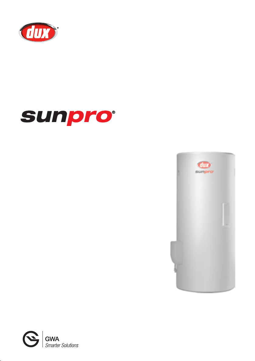
Electric Boosted Solar Water Heater
Models: 2F136S
3F136S
4F136S
Installation Details
Owner’s Information
Warranty
For advice, repairs and service, call:
1300 365 115 (Australia)
0800 729 389 (New Zealand)
Carefully remove all packaging and
transit protection from the heater before
installation. Dispose of the packaging
responsibly using re-cycling facilities
where they exist.
Specications and materials may change without notice.
Effective for Dux electric boosted solar water heaters manufactured and sold after 1 April 2009.
H3100 10346 Rev. G
Page 2

Owner’s Manual – Electric Boosted Solar
Contents
Welcome To Dux Hot Water 1
Installation of the Tank 2
Plumbing Connections 4
Specications 7
Installation of Collectors 10
Plumbing Connections to
Collectors 11
Electrical Connections 15
Hotlogic Connections 16
Owner’s Information 17
Troubleshooting 21
Warranty 23
Warranty Card 26
© Dux Manufacturing Limited 2011. All rights reserved.
H3100 10346 Rev. G
Page 3
Owner’s Manual – Electric Boosted Solar
Welcome To Dux Hot Water
Your decision to purchase a Dux Hot
Water system will reward you for many
years to come.
Since 1915, the Dux range has seen
continuous research and development,
resulting in many breakthroughs in the
efciency, reliability and longevity of hot
water systems.
Dux water heaters are manufactured
in Australia in a state-of-the-art facility,
using a Quality Endorsed Company
production system.
This is your assurance that you have
purchased the highest quality water
heater available, one that will provide
continuous hot water for all your needs
– safely, economically, and for many
years to come.
To be upfront about it, we want Dux to
be your brand of choice. So you can
depend on us to provide more than just
a hot water system.
Go with Dux and you’ll have a
dependable, economical, efcient hot
water system designed to perform well,
year after year. And that’s a promise.
You can rely on Dux products and
choose them with condence. We’ll
make sure you have the information, the
quality and the innovation you’re looking
for, including the latest energy-saving
alternatives. If you should ever have a
problem – and we’ll bet you won’t –
you’ll nd that we’re easy to get hold of,
friendly to talk to and quick to act. Our
service is all about providing anything
you need as soon as you need it.
H3100 10346 Rev. G
1
Page 4
Owner’s Manual – Electric Boosted Solar
Installation of the Tank
Installer’s Guide
Full and detailed installation instructions
are in the Installer’s Guide, included
inside the water heater’s carton.
Location
The water heater should be located as
close as possible to the most frequently
used hot water outlet. Ensure that the
data plate is clearly visible and provide
adequate access for service to the
thermostat, relief valve and anode.
Note: All models are equipped with a
sacricial anode, accessible through the
top cover. Allow 50% of the height of
the water heater for clearance above to
replace the anode.
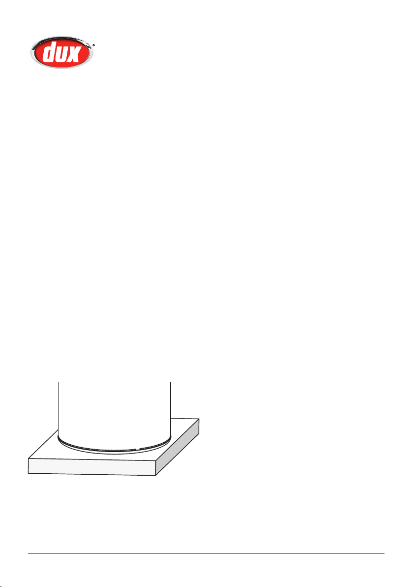
We recommend a plinth be installed
under the water heater where the
water heater is subjected to wet
conditions
A properly drained overow tray must
be used where property damage could
occur from water spillage. (See AS/
NZS3500.4 for further details.)
Note: Warranty does not cover
consequential damage due to heater
leakage.
Safety
This appliance is not intended for use
by persons (including children) with
reduced physical, sensory or mental
capabilities, or lack of experience and
knowledge, unless they have been given
supervision or instruction concerning
use of the appliance by a person
responsible for their safety.
Children and animals should be
supervised to ensure that they do not
interfere with the appliance.
2
H3100 10346 Rev. G
Page 5
Owner’s Manual – Electric Boosted Solar
Installation of the Tank
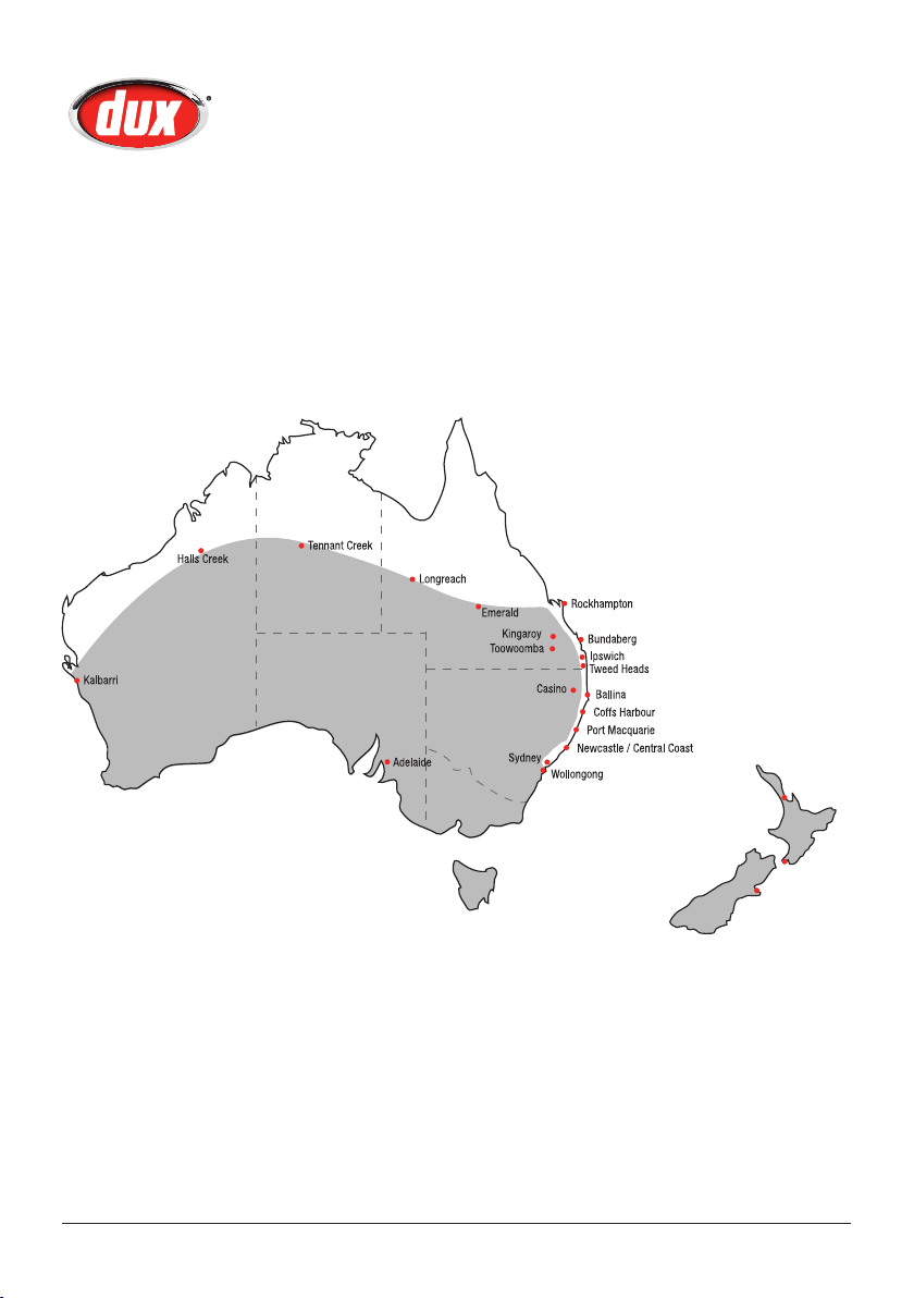
Frost Protection
The areas in gray in the map below may
be vulnerable to frost. Solar hot water
heaters installed in these areas require
an approved antifrost protection device
to maximise system performance.
H3100 10346 Rev. G
Auckland
Wellington
Christchurch
3
Page 6

Owner’s Manual – Electric Boosted Solar
Plumbing Connections
Installation Requirements
This water heater must be installed
by a licensed tradesperson, and in
accordance with:
• AS/NZS3500.4 “National Plumbing
and Drainage Code Hot Water
Supply Systems – Acceptable
Solutions”.
• Clause G12 of the New Zealand
building code.
• Local authority regulations.
• Outside Australia and New Zealand,
please refer to local plumbing and
building codes and regulations.
• Notice to Victorian customers
from the Victorian Plumbing
Industry Commission – this water
heater must be installed by a
licensed person as required by the
Victorian Building Act (1993). Only
a licensed person will give you a
compliance certicate, showing
that the work complies with all
the relevant Standards and only a
licensed person will have insurance
protecting their workmanship for 6
years.
Water Supply Pressure
This water heater is designed for direct
connection to water supply pressures of
no greater than:
or uctuate beyond the pressure
shown above, a pressure limiting
device (complying with AS1357) must
be tted in the cold water inlet supply.
This device must be installed after
the isolating valve and set below the
pressure shown above. Note during
periods of lower demand water pressure
may increase.
Pool Heating
This water heater must not be used for
pool heating.
Pressure & Temperature Relief
Valve
The Pressure & Temperature Relief Valve
is supplied loose with the water heater.
The valve rating is:
All Models – 1000kPa
The PTR valve must be installed directly
into the top socket marked “RELIEF
VALVE”. The drain line from this valve
must run in a continuously downward
direction in a frost-free ambient position
with the discharge end left open to
atmosphere permanently.
The PTR Valve is not intended to enable
connection of the water heater to
supplementary energy sources such as
solar panels or slow combustion stoves
(refer AS/NZS 3500.4 for guidance on
these types of installations).
All Models – 800kPa
Where the mains pressure can exceed
4
Open the PTR Valve for approximately
10 seconds by lifting the lever on the
valve to ensure water is relieved to waste
H3100 10346 Rev. G
Page 7
Owner’s Manual – Electric Boosted Solar
Expansion
Isolating Valve
Plumbing Connections
through the relief drain pipe. Lower lever
gently and check that it closes correctly.
The PTR Valve must not be tampered
with or removed. The water heater must
not be operated unless this valve is
tted and in working order.
The PTR Valve should be checked for
adequate performance or replaced at
intervals not exceeding 5 years, or less
in areas where local regulations apply.
Important: The PTR Valve and its
drain outlet pipe must not be sealed or
blocked. It is normal for the PTR valve
to leak a small amount of water during
heating cycles.
Danger
Failure to operate the relief valve easing
lever at least once every six (6) months
may result in a problem with the water
heater and in some cases the tank may
explode.
Warning: A separate drain line must be
run for this relief valve. It is not permitted
to couple drain lines from relief valves
into a single common drain line.
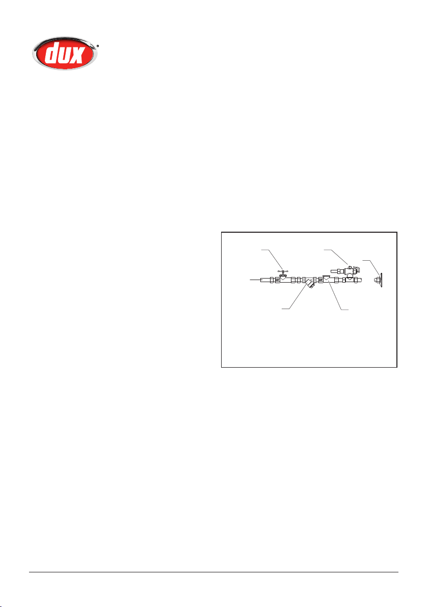
Cold Water Connection
An approved isolating valve, non
return valve, line strainer (optional but
recommended), and union must be
tted between the supply main and the
RP¾"/20mm T tting connected to the
socket in the water heater.
All ttings must be approved by the
relevant Authority and in accordance to
the plumbing code.
(Spindle Vertical)
Cold Water
Inlet
Line
Strainer
Note: a combined isolating valve/nonreturn valve/line strainer may be used.
Expansion valve only required where local
regulations demand.
Valve
Union
Connection
Non-return
Valve
Note for S.A. and W.A.: It is a state
requirement that a pressure relief valve
be tted on the cold water supply line
between the non return valve and the
water heater
H3100 10346 Rev. G
5
Page 8

Owner’s Manual – Electric Boosted Solar
Plumbing Connections
Hot Water Connection
The hot water line should be connected
to the “OUTLET” socket on the tank.
All hot water lines must be insulated
with minimum 13mm UV stabilized
insulation suitable for solar working
temperatures, e.g. Armaex Insulation.
Please check local regulations regarding
the use of hot water supply pipework
other than pipes made of copper.
Note: Once all connections have been
properly made, ll tank by opening
the cold water inlet and bleed all lines
according to appropriate plumbing code.
Safety Information
For safe performance this water heater
is tted with:
• an over-temperature energy cut-out
thermostat
• a combination Pressure &
Temperature Relief Valve.
These devices must not be tampered
with or removed. The water heater must
not be operated unless both of these
devices are tted and in working order.
Insulation of Pipes
All hot water pipes must be insulated
with UV stabilized insulation suitable
for solar working temperatures, e.g.
Armaex Insulation.
Temperature Protection
All solar water heaters have the ability
to produce hot water very quickly.
To reduce the risk of scald injury, it is
mandatory under the requirements of
Australian Standard AS/NZS3500.4.2
that a suitably approved temperature
control device be tted to the hot water
supply to outlets used primarily for
personal hygiene. This valve should be
checked at regular intervals to ensure its
operation and settings remain correct.
Note: All Dux solar water heaters are
supplied with tempering valves. Any
adjustment to the valve should be
made according to the manufacturer’s
recommendations.
The tempering valve should be checked
at regular intervals to ensure its
operation and settings remain correct.
The element cover should be removed
only by a qualied electrician. The
electrical power supply must be
isolated at the main electrical supply
switchboard before the water heater
electrical cover is removed.
6
H3100 10346 Rev. G
Page 9
Owner’s Manual – Electric Boosted Solar
6
Specifications
7
3
5
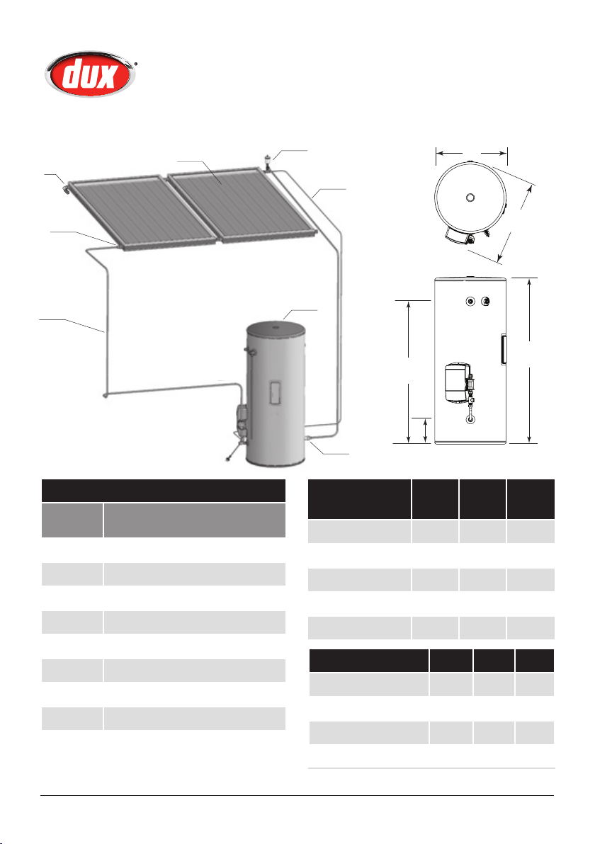
System Components
Item
Description
Number
1 Solar Electric Tank Assy
2 Solar Collector
3 Solar Collector flow connection
4 Solar Collector Sensor Lead
5 Solar Collector Flow
6 Air Bleed Valve
7 Anti-Frost Valve (if fitted)
8 Non Return Valve
2
4
1
D
E
8
Dimensions
(mm)
250L 315L 400L
B
C
A
Tank Height (A) 1444 1754 1703
Tank Diameter (B) 617 617 705
Tank Width (C) 718 718 806
Outlet (D) 1231 1541 1466
Inlet (E) 215 215 240
Specifications 250L 315L 400L
Storage Capacity (L) 259 324 416
Hot Water Delivery (L) 250 315 400
Net Weight Empty (kg) 90 105 120
Relief Valve Pressure (kPa) 1000 1000 1000
H3100 10346 Rev. G
7
Page 10

Owner’s Manual – Electric Boosted Solar
Installation of Collectors
Installer’s Guide
Full installation instructions for the
collectors are in the Installer’s Guide,
included inside the water heater’s carton.
Safety
Do not commence an installation until
you have satised yourself that all safety
issues associated with working on and
lifting components onto a roof have
been addressed.
Local Authority Regulations
All work associated with the installation
must comply with local authority
regulations, including AS/NZS 3500.4.2.
Where these installation instructions and
local regulations are in conict, local
regulations must prevail.
Location of Collectors
There are several factors to consider in
selecting the collector location site:
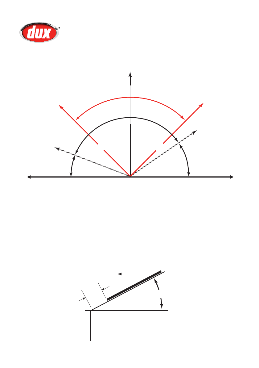
• For best performance, the collectors
need to face true north. Due to the
high solar energy levels experienced
in Australia, installations on angles
of up to 45° away from true
north should not have a major
effect on the annual solar output.
Consequently, installations up
to 45° away from true north
are acceptable. See Collector
Orientation Compass on page 9.
• If the collectors are installed with an
east facing bias, the best solar input
is achieved in the morning and if
there is a west facing bias, the best
solar input is in the afternoon.
• The collectors should be installed
with a minimum inclination of 10°
and a maximum inclination of
45°. See Collector Inclination Guide
on page 9.
• Careful site inspection is required to
ensure the selected location is not
subjected to shading from adjacent
trees or buildings at any time of the
day, but particularly between 9am
and 3pm, the highest solar input
times.
• Remember that shadows are longer
in winter than in summer, so a
site that is free of shadows from
adjacent objects in summer may
have some shadows in winter.
• To optimise efciency, the collectors
should be as close as possible to
the storage tank.
• For best performance, the collectors
should be located no more than
20m from the storage tank.
• Ensure that the roof structure is
suitable to support the weight of
the collectors. The collectors weigh
approximately 40kg each when full.
8
H3100 10346 Rev. G
Page 11
Owner’s Manual – Electric Boosted Solar
Collector Orientation Compass
Installation of Collectors
True North
NW NE
A
B
70° from
true north
45°
45°
C
Surface Plate
A. Dux preferred range
B. Industry accepted range
C. If orientations A or B are not practical, an additional collector can be
installed at the home owner’s discretion in range C (not required north
of Tropic of Capricorn)
Note: When establishing the correct Collector Orientation, please account
for the Magnetic Declination of your geographic location
Collector Inclination Guide
50° from
true north
C
EastWest
H3100 10346 Rev. G
True North
A
A = 500mm, or greater if roof allows
B = Between 10° and 45°
B
9
Page 12
Owner’s Manual – Electric Boosted Solar
Installation of Collectors
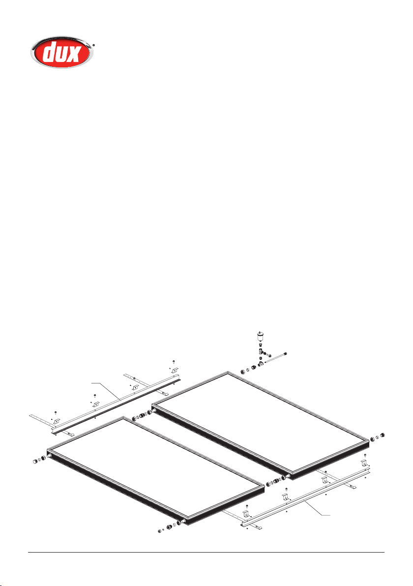
Collector Rail Kit
The Collector Rail Kit that comes
with this water heater is designed
for mounting the collectors to most
common Australian roof types.
All kits consist of specially designed
rails, clamps and bolts etc. that are used
to x the collectors to the roof structure.
With the exception of the copper tube
and roong bolts, these kits contain all
of the plumbing components required
to connect the collectors to the ground
mounted water heater.
Refer to the collector rail kit instructions
located in the rail kit box. The rail kit
instructions can also be obtained from
Dux Service on 1300 365 115.
Collector mounting rail
For installations requiring three
collectors, an additional Collector
Rail Kit is required as an extension to
increase the mounting capacity from
two to three collectors.
Roof Space
It is not advisable to install collectors
on roof spaces that are smaller than
described below:
• 2 collectors: 3m wide × 3m high
• 3 collectors: 4.5m wide × 3m high
Roof areas smaller than these minimum
measurements will make installation and
later service work difcult.
10
Collector mounting rail
H3100 10346 Rev. G
Page 13
Owner’s Manual – Electric Boosted Solar
Plumbing Connections to
Collectors
Insulation
Irrespective of the pipe length, both
the solar ow and return lines must be
insulated with UV stabilized insulation
suitable for solar working temperatures,
e.g. Armaex DuoSolar/Solar insulation.
No Plastic Fittings
Only DR brass and copper pipes and
ttings must be used. Plastic ttings and
PVC pipes are not able to withstand
the high temperatures >200ºC that the
system can create. Failure to use ttings
with a high temperature rating will void
the warranty.
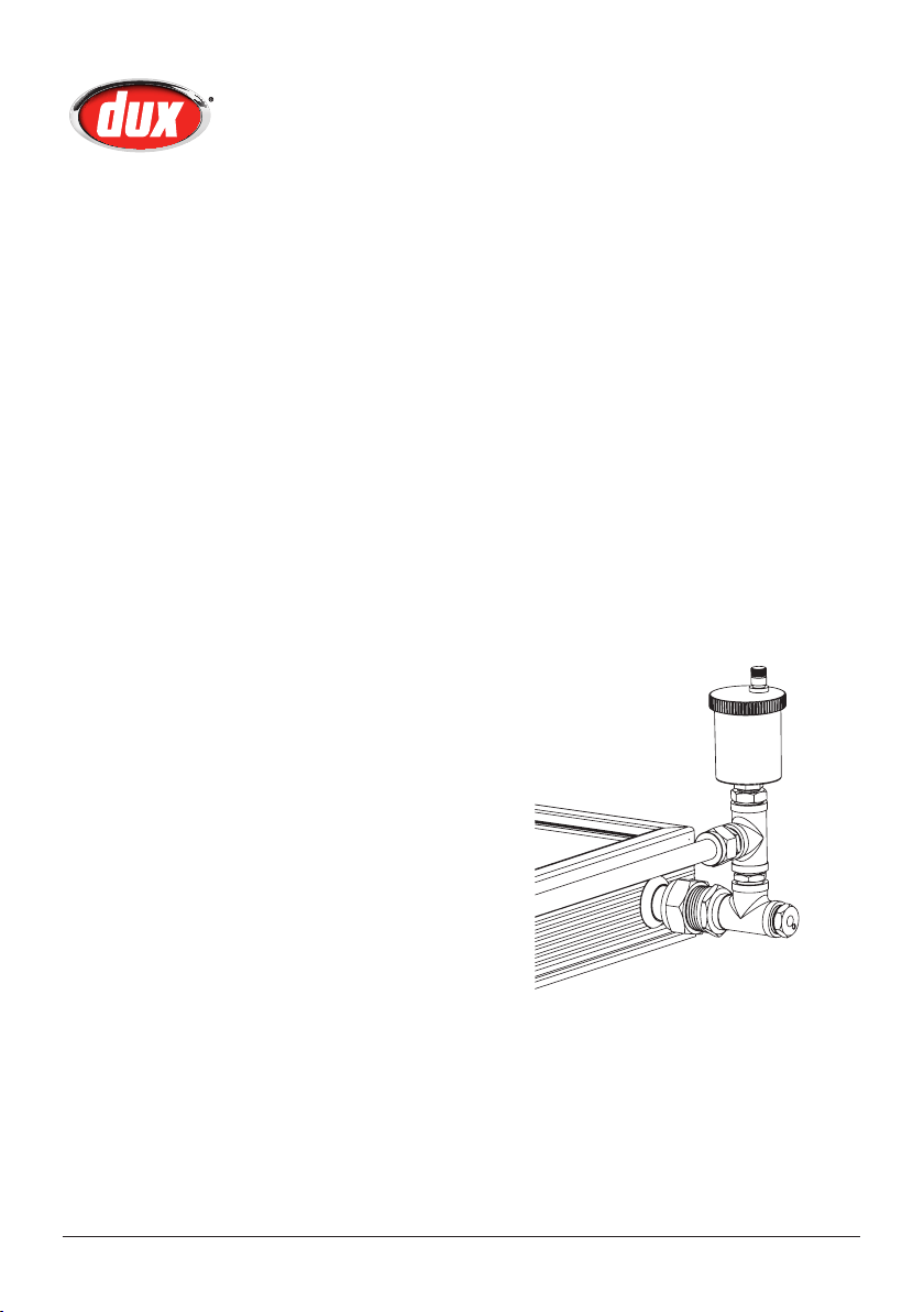
Connections To The Collectors
Connect the sealing ttings to the four
outer connections on the collector array:
1. Fit a sealing washer and plug
assembly to the top left and bottom
right corners of the array.
a. Tighten the assembly taking
care not to twist the copper
tubes of the collector.
b. Ensure you use correctly sized
spanners.
base tting to the top right hand
socket of the collector array.
4. Place the Hot Connection Union
assembly onto the union base then
tighten with the air bleed valve
vertical. (NB: The air bleed valve
should be at the highest position on
the collectors).
5. Finally insert a washer and ¾" to
½" conetite union to the lower left
collector socket.
The collector array is now completed
and ready for connection to the water
heater system.
2. Screw t the Air Bleed Valve into
the top
tighten until the nylon ring seals
against the socket face.
Important: Please open the knob
on top of the valve two turns anti
clockwise.
3. Fit the sealing washer and union
H3100 10346 Rev. G
3
⁄8" BSP socket and hand
11
Page 14
Owner’s Manual – Electric Boosted Solar
Plumbing Connections to
Collectors
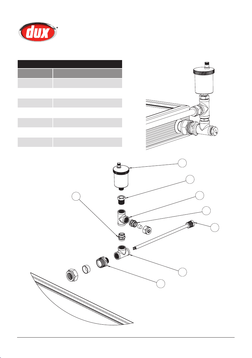
System Components
Component Description
1 Air bleed valve
2 Bush
3 15mm Female Tee
4 Union 15mm M × 15mm C
5 Sensor Dry Well
6 Hex nipple
7 Union 1" C × 1/2" M
1
2
12
6
3
4
5
3
7
H3100 10346 Rev. G
Page 15

Owner’s Manual – Electric Boosted Solar
Plumbing Connections to
Collectors
To make the connection between the
solar collector array and the storage
tank, the following is required.
1. 2 × ½" (15 mm) copper pipes, run
from the collector array down to
storage tank.
Note: Pipes must be insulated
with minimum 13mm UV stabilized
insulation suitable for solar working
temperatures, e.g. Armaex
insulation.
2. 1 × 2 core cable (supplied in kit)
run from the collector array to the
storage tank.
To complete this connection, do the
following:
1. Connect one ½" insulated copper
tube to the ½" BSP Compression
Union Assembly at the bottom
left hand corner of the array and
run down to the ground mounted
storage tank location. This tube
is known as the Collector Cold
Connection.
2. Connect the second ½" insulated
copper tube to the Hot Connection
assembly at the top right hand
corner connection of the array and
run down to the ground mounted
storage tank location. This tube
is known as the Collector Hot
Connection.
3. Connect the 2 core cable (20
metres – supplied) to the two wires
of the BLACK insulated temperature
sensor (RED ring around the wire
to indicate for hot water). Ensure
that the connection is secure and
safe. Use a connector block. Insert
the temperature sensor into the
temperature sensor well of the
hot connection union assembly.
Fix in place using cable bracket
connected to hot connection tting
and seal using a small amount of
silicon adhesive/sealant. Run the
cable down to the ground mounted
storage tank location. (It is important
that the sensor cable DOES NOT
contact the hot collector return
pipe). This sensor is known as the
Collector Temperature Sensor.
Ensure that the sensor wire does
not come in contact with the hot
collector return pipe.
Note: Care must be taken to ensure
that all roof penetrations are sealed to
prevent water ingress and to comply
with all local regulations.
H3100 10346 Rev. G
13
Page 16
Owner’s Manual – Electric Boosted Solar
RELIANCE
FLOW
Flow Direction Arrow
Storage tank
Plumbing Connections to
Collectors
Connections At The Ground
Mounted Storage Tank
Note: The tank has been pre congured
for the hot collector return to be
connected to the right hand side of
the tank (as marked). The left hand hot
outlet is for the hot water supply to the
house.
Finally, take the collector temperature
sensor cable and pass them through the
bottom of the Hotlogic module, then up
into the upper section.
Connect the collector temperature
sensor cables to the vacant terminals
(refer to page 16, Hotlogic Connections).
The polarity of the connections is not
important.
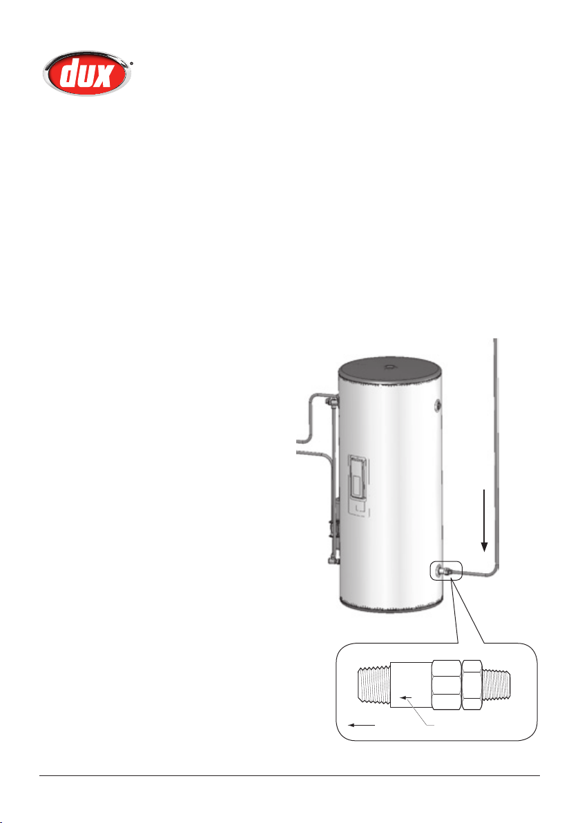
Non Return Valve
The hot water return pipe from the solar
collector should have a solar non return
valve tted where the pipe enters the
tank.
Note: Dux recommends an RMC non
return valve, product code SNR502. All
pipe work must be insulated.
Ensure the non return valve is installed
according to the ow direction arrow on
the valve.
Hot
Water
Flow
Direction
14
H3100 10346 Rev. G
Page 17

Owner’s Manual – Electric Boosted Solar
Electrical Connections
This water heater is designed for
connection to the following:
1. Solar Pump Module –
CONTINUOUS TARIFF must be
used.
2. Tank Boost – Off Peak, single
phase 240V A.C. supply. A 15 amp
power supply is needed.
Note: This Water heater is also
designed to allow the tank boost to be
connected to continuous tariff to satisfy
heavy daytime users of hot water that
exceed the capacity of the off peak
boost option.
The electrical connection must comply
with Local Supply Authority Regulations
and AS3000.
For models not pre-wired with a exible
lead, connections are made at the
terminal block under the element cover.
Entry to the connection area is through
the hole below the element cover,
designed to accept a 20mm conduit.
For the electrician, the access cover
may be removed by undoing the two
screws on the cover and sliding the
cover downward to disengage it from
the case. Ensure that the conduit entry
is well sealed to achieve complete
weatherproong.
Note: The water heater is tted with a
thermostat and over-temperature energy
cut-out. Under no circumstances should
the water heater be operated without
both these devices being in the circuit.
Replacement must be carried out only by
a qualied electrician or the manufacturer.
Danger: The operation of the thermal
cut-out indicates a possibly dangerous
situation. Do NOT reset the thermal
cutout until the water heater has been
serviced by a qualied person.
Power Cables
Power cables should be routed away
from any hot water pipes. If this is not
practical, insulate the hot water pipes
to avoid direct contact with the power
cables.
If the power cable is damaged, it should
be replaced by a lead assembly available
only from Dux service agents.
Pump Module Electrical Connection (All Models)
1. All electrical work must comply with
local regulations.
2. All electrical work must be
conducted by a licensed electrician.
3. The electrical supply to the pump
module must be continuously
available. Off Peak power must not
be used.
Caution: The water heater must be
lled with water before turning on the
electricity supply.
Electrician: Press the reset button
on thermostat(s) to ensure overtemperature cut-out is set.
H3100 10346 Rev. G
15
Page 18
Owner’s Manual – Electric Boosted Solar
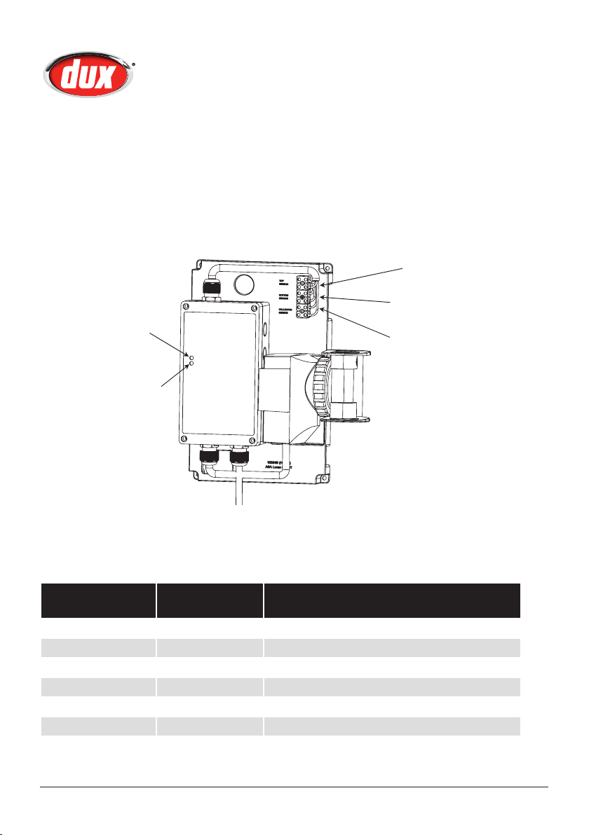
Bottom Tank Sensor (BLACK)
Top Tank Sensor (GREY)
Hotlogic Connections
Hotlogic Solar Pump
And Controller Module
The Hotlogic box should be plugged
in to a weatherproof approved power
outlet for 10 amps, 230 to 250 volt, 50Hz
continuous supply.
Status
LED
(Red)
Power
LED
(Green)
The Hotlogic controller must be wired
according to the diagram below.
Collector Sensor
(2 Core Speaker Wire)
Hotlogic Diagnosis Codes
Power LED
(Green)
Alternating Power on initialisation (LEDs blink alternately)
On Off All sensors normal, pump off
On On All sensors normal, pump on or booster on
Flashing Off Sensor error (collector or tank)
Off Flashing Tank bottom sensor error
Flashing Flashing Tank top sensor error
Note: If any sensor is open circuit, the system will indicate a Green only flashing LED.
16
Status LED
(Red)
Explanation
H3100 10346 Rev. G
Page 19

Owner’s Manual – Electric Boosted Solar
Owner’s Information
How Does My System Work?
The main components of your solar
water heater are the water storage
tank, the solar collector(s), the patented
Hotlogic controller and the Ancillary
Energy Support (AES) or electric
booster. The Dux water storage tank is
used to store the heated water ready for
household use. It is a specic Solar Dux
electric storage tank, incorporating a
high temperature vitreous enamel lining
to provide long life, and a high density
polyurethane insulation to ensure
minimal heat loss.
The solar collectors contain a multi tube
copper water way system bonded to a
solar absorber plate, the combination of
which collects solar energy and transfers
it to the uid within the collector circuit.
The absorber plate system is enclosed
in an insulated casing covered with a
high strength, low iron glass sheet that
protects the absorber system from
physical damage.
The Ancillary Energy Support System
(electric boosting – connected to
continuous electricity supply) is used to
heat part of the stored water on those
occasions when there is reduced solar
energy available, e.g. cloudy days.
The AES System is thermostatically
controlled so it only delivers the energy
required, then automatically turns off.
Under normal operating conditions, the
water within the storage tank is heated
by the solar collectors.
In an Open Circuit system, the water is
in the collector circuit and the circulating
pump draws cold water from the cold
inlet or the bottom of the tank and
pushes it up into the solar collectors.
The water is heated in the collector
by absorbing heat from the sun and
continues on its pumped circulation path
back to the bottom (opposite to the inlet)
of the storage tank, ready for use.
What Does The Circulation Pump Do
In The System?
The circulation pump is a simple device
used to circulate the water in the
collector circuit. This, in turn, enables
solar energy from the collectors to be
transferred to the storage tank location.
The pump consumes only a very small
amount of electrical energy (less than
28 watts) to perform this task. The
circulation pump has an integral ‘nonreturn valve’ to prevent solar energy
from reverse cycling back through the
storage tank to the collectors at night.
The electronic control device used
to control the circulation pump has a
complex set of activities. It is the brain
of the system and ensures optimum
system efciency and safety. The basic
functions are:
1. Detecting availability of useful solar
energy in the solar collectors.
When the temperature of the solar
collector is 10°C higher than the
storage tank temperature, the
H3100 10346 Rev. G
17
Page 20

Owner’s Manual – Electric Boosted Solar
Owner’s Information
circulation pump is initiated. If the
difference in temperature falls to
less than 2°C the circulation pump
is stopped.
2. Controlling maximum storage tank
temperature. If the storage tank
temperature reaches 85°C, the
circulation pump is stopped to
prevent excessive temperatures in
the storage tank.
3. Frost Protection. When the
temperature of ambient conditions
adjacent to the collector sensor
drops to 5°C the circulation pump
will start and run for a minimum of
5 minutes to prevent the collector
from freezing. The pump circulates
hot water from the storage tank
through the collectors until the
collector sensor registers that the
collector temperature has been
raised to 9°C, at which point the
pump is shut down.
How Long Will The Heater Run
Each Day?
The length of time that the solar heater
will run each day will vary dependent
upon the amount of hot water being
used by the household and the
availability of sunlight to heat the solar
collectors.
Caution: All water heaters have
the ability to produce hot water in a
surprisingly short time. To reduce the
risk of scald injury, it is mandatory
under the requirements of Australian
Standards AS3500 that an Australian
Standards approved temperature
control valve be tted to the hot water
supply pipe work. This valve should be
checked at regular intervals to ensure its
operation and settings remain correct.
4. Anti Frost Valve. A secondary
level of protection has also been
provided through the use of an
Anti Frost Valve. This valve opens
and releases water from collectors
when ambient air temperatures are
between below 2°C and 4°C. The
valve also isolates the collector and
connecting pipework from the tank
to prevent the loss of heated water
from the tank.
18
H3100 10346 Rev. G
Page 21

Owner’s Manual – Electric Boosted Solar
Owner’s Information
What Should I Do During Holidays?
The system can monitor and control
the solar collector temperature while
you are away. Whilst the system is safe
with the power turned OFF, the collector
temperatures can reach very high
temperatures, causing high stress to
their internal components.
The power supply to the solar
controller Hotlogic pump module
must be left ON.
Warning: If the hot water system is
not used, for two weeks or more, a
quantity of hydrogen gas, which is highly
ammable, may accumulate in the water
heater. To dissipate this gas safely, it is
recommended that a hot tap be turned
on for several minutes at a sink, basin
or bath but not a dishwasher, clothes
washer, or other appliance. During this
procedure there must be no smoking,
open ame or any other electrical
appliance operating nearby. If hydrogen
is discharged through the tap, it will
probably make an unusual noise similar
to air escaping.
Note: Important there are no user
serviceable components in the
system. Only an authorised service
representative is permitted to remove
any covers or make setting adjustments.
Do not open or adjust any electrical
covers or devices yourself.
The Dux solar water heater is designed
such that there is little to do regarding
system maintenance other than that
detailed in this Owner’s Manual. The
components in the solar side of the
system do not require maintenance.
Personally inspecting or servicing any
part of the system is not recommended.
Should you decide to personally inspect
the roof mounted system components,
it is essential that you use all safety
devices required to ensure your safety.
After each 5 years of operation you
should contact the local service agent
to replace all safety valves and anodes
to ensure continued system life and
operational safety. In locations where
the water has a TDS greater than 600
ppm, this service is recommended each
3 years.
Water Quality
Your Dux water heater has been
manufactured to suit water conditions of
most Australian metropolitan supplies.
Please note that harsh water supplies
can have a detrimental effect on the
water heater and its life expectancy. If
you are unsure about your water quality
you can obtain information from your
local water supply authority.
The water heater is designed for use in
areas where the Total Dissolved Solids
(TDS) content of the water supply is less
than 2500 mg/L. In areas where the
TDS exceeds 600mg/L the magnesium
H3100 10346 Rev. G
19
Page 22

Owner’s Manual – Electric Boosted Solar
Owner’s Information
alloy anode (supplied in the heater) may
become over reactive. To alleviate this,
the anode should be replaced with an
aluminium alloy anode, available from
your local Dux supplier.
Water can also be very corrosive,
measured by the saturation index. If the
water saturation index is greater than
0.40 an expansion control valve should
be tted and where the index is greater
than 0.80 the water heater installed
should be a Hard Water Model. Please
consult our Service Department for
advice if required.
Six Monthly Service – By Owner
Operate the Pressure & Temperature
Relief Valve for approximately 10 seconds
by operating the easing lever on the
valve to ensure water is relieved to waste
through the relief drain pipe. Check to
ensure the valve closes correctly.
One Year Service – By Authorised
Personnel Only
Inspect and clean pump turbine of any
foreign material (calcium or other).
If water quality is poor, carry out
inspection more frequently.
Five Year Service – By Authorised
Personnel Only
The ve year service must be carried
out by a licensed tradesperson. It is
recommended that this service be
carried out by your local Dux agent.
The service should include the following:
• Replace the Pressure &
Temperature Relief Valve.
• Replace the anodes (in areas of
harsh or adverse water conditions, a
more frequent check of the anodes
is recommended).
• Cleaning of collector panels to
improve solar collection
• Flush the water heater by doing the
following:
i. Turn off the power.
ii. Turn off the cold water supply to
the water heater at the isolating
valve.
iii. Gently operate the easing lever
on the Pressure & Temperature
Relief Valve to release the
pressure in the water heater.
iv. Disconnect the cold water inlet
union to the heater and attach a
drain hose.
v. Gently operate the Pressure
& Temperature Relief Valve to
let air into the heater and allow
water to escape through the
hose.
vi. Flush the heater until clear
water appears then reconnect
all ttings, ll the heater and
restore the electricity supply.
Draining the Water Heater
To drain the water heater, follow steps i
to v above until no more water escapes
from the appliance.
20
H3100 10346 Rev. G
Page 23

Owner’s Manual – Electric Boosted Solar
Troubleshooting
What Should I Check Before
Making A Service Call?
If there is not enough hot water, it is
recommended that the following points be
considered before making a service call.
If after checking the following points the
problem has not been identied, please
contact Dux on 1300 365 115.
Water Discharge From The PTR
Valve
Pressure & Temperature Relief Valve
(PTR)
It is normal for the PTR to allow a small
quantity of water to escape during the
heating cycle. The amount of discharge
will depend on hot water usage.
Continuous trickle (PTR)
This is most likely due to a build up of
foreign matter. In this case try gently
raising the easing lever on the Pressure
& Temperature Relief Valve for a few
seconds then release gently. This may
dislodge a small particle of foreign
matter and rectify the fault.
Steady ow (PTR) – more than
20L per day
This may be caused by excessive water
supply pressure, a faulty Pressure &
Temperature Relief Valve or a faulty
thermostat. Turn off the electricity supply
and contact your Dux agent.
No Hot Water
• Is the Pressure & Temperature Relief
Valve discharging too much water?
• Do you have the correct size water
heater for your requirements? Sizing
details are available from your Dux
supplier.
• Is one outlet (such as the shower)
using more hot water than you
think?
• Carefully review the family's hot
water usage and if necessary
check the shower ow rates with a
bucket, measuring the amount of
water used over that period of time.
If it is not possible to adjust water
usage patterns, an inexpensive ow
control valve can easily be tted to
the shower outlet.
• Consider that during night time
heating, the time taken to heat the
tank can take longer (less energy
in the air) so you may nd that the
tank has not fully recovered from a
period of heavy usage the previous
evening.
• Consider that often the hot water
usage of showers, washing
machines and dishwashers can
be under estimated. Review these
appliances to determine if your daily
usage is greater than the storage
volume of your water heater. If
for example you have a 315 litre
storage tank and you are using
H3100 10346 Rev. G
21
Page 24

Owner’s Manual – Electric Boosted Solar
Troubleshooting
450 litres of water it is possible that
there will be certain times of the
day where there is insufcient hot
water. It is also advisable to inspect
tap washers etc. for leakage and
replace if necessary.
• Is there a leaking hot water pipe or
dripping hot water tap? A small leak
can waste a large quantity of hot
water.
• Replace faulty tap washers and
have your plumber rectify any
leaking pipe work.
Condensation in Collectors
In winter, or in times of heavy rain, water
vapour may form in the warm and humid
solar collectors, and then condense on
the inside surface of the cold glass.
As solar collectors are insulated for
optimum performance and have minimal
internal airow, condensation that has
formed during these times takes a
longer time to disperse but will do so
when enough direct sunlight has come
in contact with the collectors. The
warmer the sunlight, the faster it will
disperse.
Condensation in the collectors does not
affect the system’s performance.
High Electricity Bills
Low Solar Energy Input
If there have been prolonged periods
of cloudy weather, or winter is
approaching, it may be necessary to
reconsider the permitted AES allowance
for time-clock controlled systems, or
to turn on the AES for systems with a
booster isolation switch.
Solar Collector Shading
Often trees or other buildings can shade
the solar collectors, or there can be
dirt build up on the glass cover. Trees
should be cut back if possible, or the
system relocated if removal of the
shading is not possible, in the present
location. If the glass is dirty, this should
be cleaned with any normal domestic
glass cleaner – recommended to be
done by an authorised tradesperson.
Often the hot water usage of showers,
washing machines and dishwashers
is under estimated. Review these
appliances to determine if your daily
usage is greater than the storage
volume of your water heater.
It is also advisable to inspect tap
washers etc. for leakage and replace if
necessary.
22
H3100 10346 Rev. G
Page 25

Owner’s Manual – Electric Boosted Solar
Warranty
Dux Hot Water Unit
Manufactured by Dux Manufacturing Limited (“Dux”)
Terms of Warranty and Replacement Guarantee
All Sunpro Electric Boosted Solar
water heaters manufactured and sold
after 1 January 2011 are backed by a
comprehensive one (1) year full parts
and labour warranty (conditions apply –
see below).
Furthermore, the Sunpro Electric
Boosted Solar tank and solar collectors
include a guarantee to replace your hot
water unit if the inner cylinder fails within
ve (5) years and to replace the solar
collector if it fails within ve (5) years
(conditions apply – see below).
The terms of the Warranty and
replacement guarantee are set out
below.
1 Year Comprehensive Warranty
Your Sunpro Electric Boosted Solar
hot water system and its components
are covered by a one (1) year (parts
and labour) warranty against defective
factory materials or workmanship from
the date your hot water unit or solar
collector/s is installed or two (2) years
from date of manufacture, whichever
occurs rst.
5 Year Replacement Guarantee
If an inner cylinder or solar collector
fails on a Dux hot water unit within a
further four (4) years after the end of
the initial one (1) year warranty period,
Dux will provide a free replacement hot
water unit and/or solar collector at the
nearest approved Dux agent or Dux
ofce to the owner’s home. Under this
replacement guarantee, the transport,
installation and labour costs of delivering
the replacement hot water unit and
removing and replacing the existing
hot water unit with the replacement hot
water unit will be the responsibility of
the owner of the existing hot water unit.
Please note that Plumbing regulations
require that the replacement collector be
re-installed by a licensed Plumber.
Scope of Warranty and Replacement Guarantee
In addition to the guarantees implied
by the Australian Consumer Law
(“ACL”), Dux provides a warranty for the
periods of time set out above (1 year
plus a further 4 years), after the date of
installation (or manufacture) of the hot
water heater (“the Unit”), that the Unit is
free from all defects in factory materials
or workmanship under normal use.
If the Unit fails to conform to this
warranty during the applicable period,
Dux will replace any failed component
or where necessary, in the absolute
discretion of Dux, replace the Unit free
of charge including reasonable labour
H3100 10346 Rev. G
23
Page 26

Owner’s Manual – Electric Boosted Solar
Warranty
costs incurred in normal business
working hours.
Note: Where the date of completion
of installation is not known, then this
warranty will commence one (1) month
after the date of manufacture (refer to
the data label on the Unit).
This warranty only applies to defects
which have arisen solely from faulty
materials or workmanship in the Unit
and does not apply to other defects
which may have arisen as a result
of, without limitation, the following:
accidental damage, abuse, misuse,
maltreatment, abnormal stress or strain,
harsh or adverse water conditions
including excessive water pressure or
temperature, or neglect of any kind
of the Unit. Alterations or repair of the
Unit other than by an accredited and
licensed service agent or technician are
not covered. Attachment of accessories
or use of non genuine replacement
parts other than those manufactured
or approved by Dux are not covered by
this extended warranty.
This warranty applies only to the Unit and
does not cover any ancillary plumbing
or electrical parts supplied by the
installer such as pressure limiting valve,
tempering valve, line strainer, stop cocks,
non-return valve, electrical switches,
pumps or fuses, or faulty installation.
The Unit must be installed by a licensed
plumber in accordance with information
set out in the Owner’s Manual and/
or Installer’s Guide supplied with the
Unit and/or any relevant statutory
requirements.
In addition to this extended warranty,
certain legislation (including the ACL)
may give you rights which cannot be
excluded, restricted or modied. This
extended warranty must be read subject
to such legislation and nothing in this
warranty has the effect of excluding,
restricting or modifying those rights.
If Dux fails to meet a guarantee implied
by the ACL, your remedy for such failure
may be limited to any one or more of the
following:
• replacement of the Unit;
• repair of the Unit;
• refunding the cost of the Unit;
• payment of reasonable costs of
having the Unit repaired;
• payment in respect of the reduced
value of the Unit.
Any defective part of the Unit must be
returned to the point of sale before
replacement can be considered under
the terms of this warranty. If the costs
of returning any defective parts are
unreasonable, please contact Dux on
1300 365 115 (Australia) or 0800 729
389 (New Zealand) so that we can
arrange a collection if appropriate.
Warranty claims can be made at the
point of sale or by posting or faxing a
24
H3100 10346 Rev. G
Page 27

Owner’s Manual – Electric Boosted Solar
Warranty
warranty claim to Dux (contact details
listed below) within one (1) month of the
appearance of a defect. Warranty claims
under this extended warranty must
include the following details:
• Date of Purchase;
• Location of Purchase;
• Proof of Purchase;
• Contact Details
• Product Serial Number
Contact details
Dux’s contact details are as follows:
Postal Address:
Dux Manufacturing Limited
PO Box 209
Moss Vale, NSW, 2577
Australia
Telephone:
1300 365 115 (Australia)
0800 729 389 (New Zealand)
or excessive labour, at the determination
of Dux, to make the Unit accessible for
repair or replacement.
As required by legislation, including
under the ACL, any claims for damage
to furniture, carpets, walls, foundations
or any other consequential loss either
directly or indirectly due to defects
of any kind in a Unit will only be met
by Dux where the damage could be
considered reasonably foreseeable.
Our goods come with guarantees that
cannot be excluded under the ACL. You
are entitled to a replacement or refund
for a major failure and for compensation
for any other loss or damage. You are
also entitled to have the goods repaired
or replaced if the goods fail to be of
acceptable quality and the failure does
not amount to a major failure.
Facsimile:
(61 2) 4868 0257
Web:
http://www.Dux.com.au
Note: If the Unit is located in a
position that does not comply with
the installation instructions or relevant
statutory requirements, then this
extended warranty does not cover major
dismantling or removal of cupboards,
doors, walls or special equipment and/
H3100 10346 Rev. G
25
Page 28

Owner’s Manual – Electric Boosted Solar
Warranty Card
Inside the water heater carton you will nd a warranty card – please ll in the details and
return immediately. This will ensure prompt service under warranty, if required.
Product Warranty is applicable only in Australia and New Zealand.
See page 23 for terms of warranty.
Privacy Act Amendment (2000): If and whenever warranty service is required, your personal
details will be given to an Authorised Dux Service Agent only for the express purpose
of carrying out the arranged warranty service work agreed by you the client and Dux
Manufacturing Limited.
Your Details
For future convenience, ll in the following details and retain with your original invoice for your
own records.
Surname:......................................Given Name(s):...................................................
Address:..................................................................................................................
Town/Suburb:..........................................................................................................
State/Territory:............................. Postcode:....................
Date of Purchase:.......................... Purchased From:............................................
Model:.................................. Serial Number:..........................................................
Date of Manufacture:..............................................................................................
(Details on Data Label on water heater)
Installer’s Details:
Date of Installation:......................... Installer’s Name:.............................................
Address:..................................................................................................................
Installer’s Signature:...................................................................................
Service Details:
Date of Service:......................... Serviced By:..........................................................
Work Carried Out:......................................................................................................
..................................................................................................................................
..................................................................................................................................
Signature of Service Agent:........................................................................
26
H3100 10346 Rev. G
Page 29

Owner’s Manual – Electric Boosted Solar
H3100 10346 Rev. G
27
Page 30

Owner’s Manual – Electric Boosted Solar
28
H3100 10346 Rev. G
Page 31

Owner’s Manual – Electric Boosted Solar
H3100 10346 Rev. G
29
Page 32
Owner’s Manual – Electric Boosted Solar
Electric Boosted Solar Water Heater
For advice, repairs and service, call:
1300 365 115 (Australia)
0800 729 389 (New Zealand)
H3100 10346 Rev. G
 Loading...