

Page 1

SPS-035 / SPS-050 / SPS-060 (12V,15V,24V)
SDS-030
User’s Menu
Please read this user's guide carefully before setup.
Input:
1. Input range:
SPS-035 / SPS-050 / SPS-060:
Universal full range AC 85V ~ 264V or DC 120V ~ 375V
SDS-030A: 9.5 ~ 18VDC / SDS-030B: 18 ~ 36VDC / SDS-030C: 36 ~ 72VDC
2. Inrush current: When turn on input power source, there is peak current (inrush
current) running through filter capacitor of power supply. During power supply
operating, it is important not to turn off input power source and then immediately
turn on it again, otherwise, it may shorten power supply’s life.
Inrush current could be several to tens times of the normal current. It is important
to make sure input wiring, fuse and SW are able to carry inrush current.
3. For input specification, please refer to the label on the product or visit
www.sunpower.com.tw
for newly update data.
Output:
1. The output voltage adjustable range is ±10% of rated output voltage. As output
power is V
x A0, when adjusting V0 to a higher value, should decrease A0 as well,
0
ex.:
For SPS-035-05, the rated output voltage is 5V, max output current is 7A: If
adjusting output voltage to 5.5V, should decrease max output current to 6.3A as
well; and even if adjusting output voltage to 4.5V, max output should not be over
7A.
2. For output specification, please refer to the label on the product or visit
www.sunpower.com.tw
for newly update data.
Protection:
1. Short circuit protection: When circuit shorted, power supply will shutdown. After
short circuit has been removed, power supply will recover automatically.
2. Over load protection: When over loaded, power supply will shutdown. After load
reduced to meet rated range, power supply will recover automatically.
3. Over voltage protection: When output voltage exceeds rated range, power will
shut down. After voltage reduced to meet rated range, it will recover automatically.
4. Input polarity reverse protection: SDS-030 series only .
To Parallel Switching Power Supplies
Adjusting output voltage of each power supply to a same level, and then serialize a
diode after the positive pole of each power supply. The diode must be able to carry
current that higher than power supply’s max output, and should be equipped with a
proper heat sink. (It is suggested to choose a power supply which max output
could meet your system’s requirement instead of paralleling lower output power
supplies)
LOAD
2
To Serialize Switching Power Supplies:
a. To up rise output voltage:
Power Supply
INPUT
INPUT
Power Supply
12V
(1)
LOAD
12V
(2)
b. To generate both positive and negative output voltage.
Power Supply
INPUT
INPUT
Power Supply
12V
12V
LOAD
LOAD
(1)
(2)
Wiring:
1. Output wiring must be thick and short enough to carry loading. The shorter and
thicker the wire, the less voltage it drops (less wire loss).
Load
V+
V-
Wire loss
2. Connecting the PE of power supply to system’s chassis with a short & thick wire
can reduce noise and prevent electric shock.
3. Reference data for wires:
AWG
Area
NO.
(mm
30 0.051 7/0.102 358 0.12 --28 0.081 7/0.127 222 0.15 0.2
26 0.129 7/0.16 140 0.35 0.5
24 0.205 11/0.16 88.9 0.7 1.0
22 0.326 17/0.16 57.5 1.4 2.0
20 0.517 26/0.16 37.6 2.8 4.0
18 0.823 43/0.16 22.8 4.2 6.0
16 1.309 54/0.18 14.9 5.6 8.0
14 2.081 41/0.26 9.5 --- 12.0
12 3.309 65/0.26 6.0 --- 22.0
10 5.262 104/0.26 3.8 --- 35.0
Constitution
2
(Wire/mm)
)
Vol. Drop/1A
mV/m
Max. Load Current (A)
U1007
(300V 80℃)
U1015
(600V 105℃)
Mounting:
1. Each power supply is enclosed with mounting screws. It is suggested to use
enclosed screws to setup power supply, otherwise, make sure it s length must not
be too long (refer to the following drawing) to cause short circuit.
2. The input wiring should be separated from output wiring to avoid noise interfere.
3. When multiple power supplies work together, be sure to keep proper distance
between power supply & power supply as well as power supply and the
environment for good air convection. Use extra cooling fans if needed.
Page 2
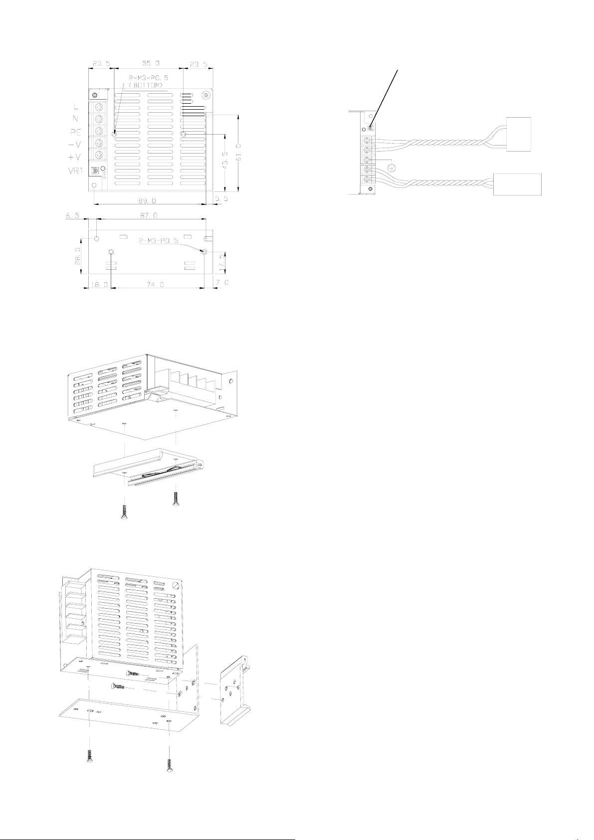
A. Mounting holes dimension:
Load
Connection:
VR1 for adjusting output voltage.
If there comes a sudden output interruption
during adjusting VR, please turn VR1 to the
middle value, and then turn on AC power again.
B. Din rail mounting: (contact your dealer to buy Din Rail brackets if needed)
60-475-160
2- M3x6
60-475-079
2- M3x6
60-475-076
V-
V+
AC / DC
Power Source
+V
-V
PE
N(Vin-)
L(Vin+)
LED
VR1
Safety terms:
1. The Y capacitor inside power supply could deliver leakage current. When multiple
power supplies work in parallel or in series, the leakage current will increase to
cause the possibility of getting electric shock. Make sure ground wire is thick
enough to prevent the danger.
2. For AC input switching power supplies, the voltage running through primary circuit
could up to 2~4 times of AC input voltage. It is forbidden for non-technicians to
open the case. Contact your local dealer for technical support if needed.
3. The temperature inside power supply may exceed 85℃ during full loading, so it is
dangerous to touch power supply at this time. Be sure to keep a proper distance
between power supply and combustible material.
Trouble Shooting:
If power supply couldn't work properly, please turn off input power SW, and check the
following steps:
1. Check all the connections (pin in/out correct? polarity correct? etc.)
2. Does terminal well connected? If not, reconnect it, and then turn on input power
source again.
3. Check load current. If over loaded, decrease loading, and then turn on input power
source again. (Rated load current show on label)
4. If there comes a sudden output interruption during adjusting VR, please turn VR to
the middle value, and then turn on AC power again.
5. If there is a temporary working followed by power supply shut down, it may cause
by a higher inrush current requirement of the system. Replace a higher output
power supply to meet the system’s requirement.
6. If environmental temperature gets too low or too high?
(1) If the environmental temperature lower than 10℃, take either of the following
steps:
a. Use heater to warm up the environment; or, b. Reduce loading.
(2) If environmental temperature higher than a certain degree, use extra cooling
fans to enforce air convection, or reduce loading. (Refer to related specification)
7. If the fuse inside power supply melted, there must be something function
abnormally. Find out the abnormal cause and remove it; and then replace a new
fuse. Make sure the new fuse’s spec must be same as the original.
If all of the above items were checked and power supply still cannot
function normally, please cont act your local dealer for support or e-mail
info
@dehner.net
SUNPOWER TECHNOLOGY CORP. operates a policy of c ontinuo us dev elopme nt. Ther efore,
we reserve the right to make changes and improvements to any of the products described in
this guide without prior notice.
© SUNPOWER TECHNOLOGY CORP. All right reserved.
URL: http://www.dehner.net
May 8, 2003 9:22 AM 84-200-013
 Loading...