

SunPower SP250U18, SP315U18, SP250H20, SP315H20, SP315U25 Operation & Installation Manual
...
Page - 1 - of 19
Sunpower
Operation / Installation manual
Version 1.1 Date: 18 Sep 2016
This manual applies to model:
SP250H25, SP315H30, SP400H40, SP500H50
Foreword
This handbook is a technical manual with instructions for the
SUNPOWER spilt system high pressure solar water heater's use.
Also contains installation instructions. Please read this handbook in
detail, before installing the SUNPOWER system. All system must
follow installation instructions strictly.
The appliance must be installed, commissioned and serviced by an
authorized person (licensed plumber) in accordance with the
requirements of AS/NZS 3500.4 or in New Zealand, NZBC G12.”
All Sunpower systems have the Australian watermark standard, and
ensure you are getting Australian quality.
Sunpower systems are also accredited with various certificates (like
EN12975 and Solar Keymark) These International certification
Page - 2 - of 19
organizations provide customers with trust and confidence in
Sunpower products
This is the common-sense warning that we have to include.
NOTE
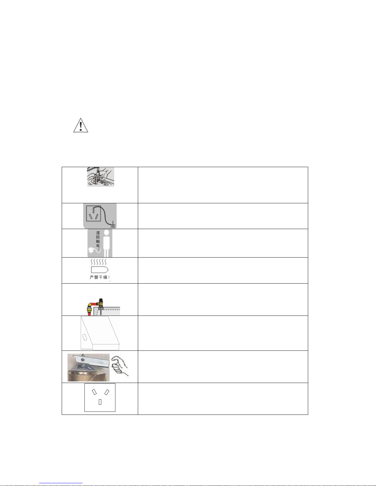
In order to guarantee that your safety, please note the following
security item, in order to avoid causes the hot water system's damage
Before using the hot water, please test the water, in the
water bowl. Use the hot water and cold water through the
mixing taps, to prevent against scalds!
All systems must be connected, with the safe ground wire
device! (earthed)
When touching the auxiliary electric heating, you must
make certain that the power is off.
The power supply must be off when there is no water in
the tank.
The T/P valve drain pipe should be located in a safe area,
or joined to a closed drain. When the T/P valve opens the
discharged water temperature is very high. If not done
safely, scalding could result.
The installed power supply outlet should have a cover over
to stop water entry. Indoor / outdoor types
We suggest that every two month you open the handle of
the T/P operating valve (slowly). If the valve does not
open, perforates the air vent with a needle or thin iron
wire.
15A ~250V
Use only Australian certified electrical power outlets.
The current capacity has to be bigger than 15A!

Page - 3 - of 19
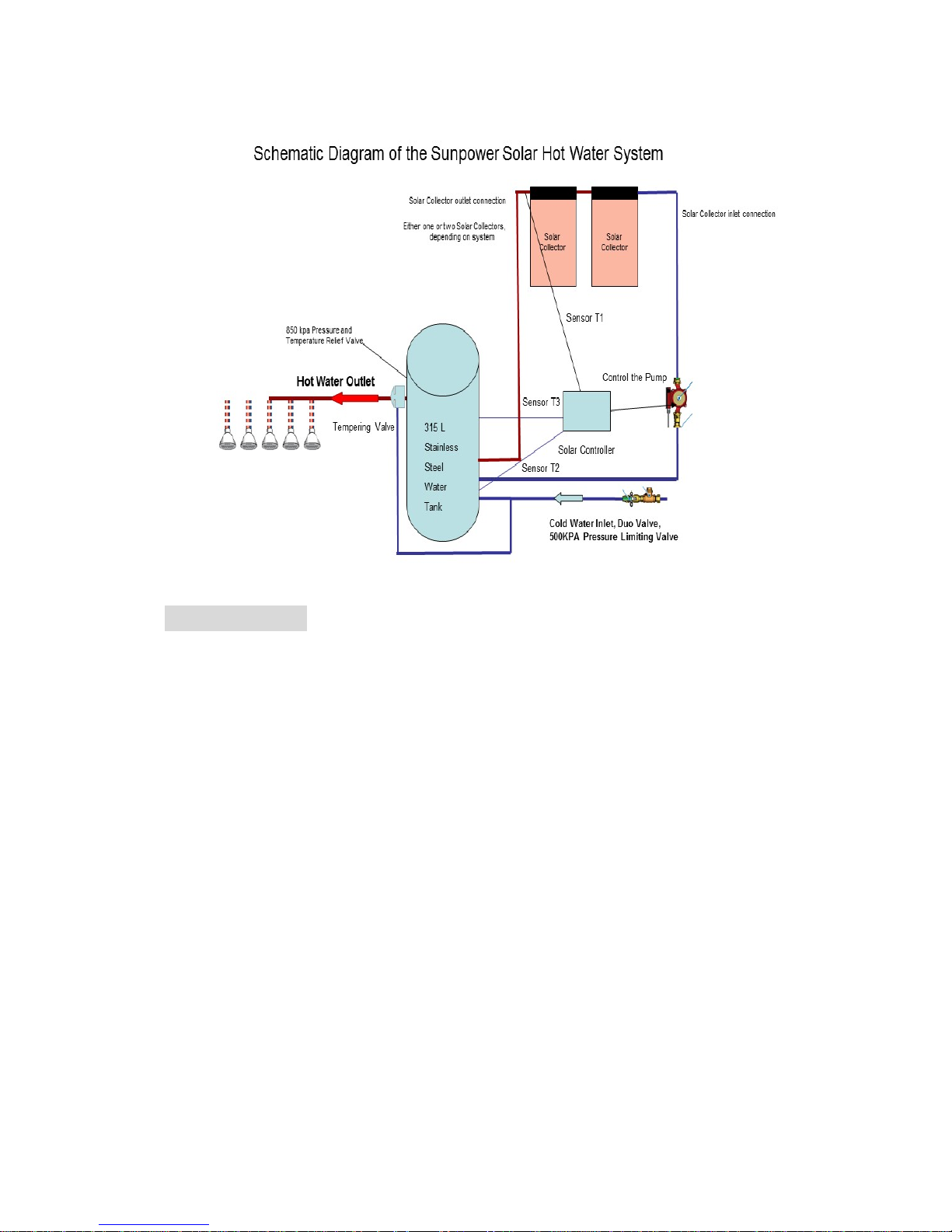
Product outline and how the Sunpower system works.
The collectors are generally installed on the roof, and the water tank on the
ground. Sunlight is collected by the evacuated tubes, and converted to heat.
This in turn heats a “copper heat pipe “inside the evacuated tube. There is a
copper pipette at the top of the tube, which has your tank water circulated
around it. The heat is then transferred to your water.
The electronic control box (supplied) has 3 sensors. One is at the outlet on
the evacuated tube manifold, one is at the bottom of the tank, and the third
is in the middle of the tank. When the control box registers a difference of
10 degrees Celsius between the outlet / bottom sensor, it switches the pump
on (supplied), until there is only 5 degrees difference. Then the pump is
switched off. This cycle repeats until such time as the middle sensor reads
80 degrees Celsius. Then the control box will not allow the pump to switch
on. This not only protects the tank, but ensures no water wastage through
the P T R valve on the tank.
Product characteristic:
Evacuated heat pipes. This means no water in tube, no possibility of scale
build up, and no cracking of the tube due to water expansion
The collector has integration modulation technology (top sensor reads 5
degrees Celsius). This allows the control box to switch the circulating
pump on in severe conditions (frost), circulates the bottom 50 litres of
water in the tank (approx), and ensures that there is no likelihood of
freezing in the copper pipes.

Page - 4 - of 19
Sunpower systems have a 3.6 Kw electric heating element in the tank.
These guarantee all weather hot water availability. They are also able to
couple to Natural gas and L P G heaters, as back up heating, instead of
using the electrical element.
All Sunpower tanks are marine grade, and stainless steel.
Product function:
The control box has digital displays for the collector and water tank
temperature
There is an inbuilt power failure automatic memory. This can guarantee
that the control box does not lose
·Automatic electric heating function
·Manual key modulation electric heating
·Fixed time electric heating
·Manual pump circulation
Tank and Collectors composition
Collector: Include evacuated tubes with heat pipe, and heat transfer
aluminum fin.
The water storage tank:Inner tank uses the SUS304-2B food grade
stainless steel plate, using the automatic welding craft processing;
Corrosion-resistance, polyurethane high temperature high insulation
The outer tank uses the color steel plate, has the very good radiation
protection (U/V), and better corrosion resistance.
Page - 5 - of 19
Main tech info.
·water tank capacity:250~500L;
·heat pipe or vacuum tube:φ58*1800;
·working pressure:≤0.6MPa;
·controller power:3W;
·The water temperature control within 2℃ ;
·The circulating pump power≤600W (Wilo pump at 22 W);
·Working voltage:Exchange 220-240V(50HZ);
·The electric heating element:≤3600W。

Page - 6 - of 19
Environmental request
1、The altitude above sea level does not surpass 3500m;
2、Controller indoor air relative humidity ≤95%;
3、Controller office work temperature - 20℃~60℃;
4、Mains pressure inlet (cold water) ≥0.1MPa;
5、Frost protection:level 2
Product specification series table
Product specification series table
Model
Tank
capac
ity
Solar collector
Heating
elements
power
(KW)
Each solar collector
size
Tank
size(mm)
height*
diameter
Collec
tor
area
(㎡
)
Working
pressure
(MPa)
Length
(mm)
Tube
NO.
(pcs
)
length*width*
height(mm)
SP250U18
250L
1800
18
3.6
1530×1520×1400
540*1800
2.43
0.1~0.6
SP250H20
250L
1800
20
3.6
1530×1680×1400
540*1800
2.71
0.1~0.6
SP315U18
315L
1800
18
3.6
1530×1520×1400
650*1540
2.43
0.1~0.6
SP315H20
300L
1800
20
3.6
1530×1680×1400
650*1540
2.71
0.1~0.6
SP315U25
300L
1800
25
3.6
2270*1120*140
650*1540
3.37
0.1~0.6
SP315H25
300L
1800
25
3.6
1530×2080×1400
650*1540
3.37
0.1~0.6
SP315H30
300L
1800
30
3.6
1530×2480×1400
650*1540
4.05
0.1~0.6
SP400U30
400L
1800
30
3.6
1530×2480×1400
650*1970
4.05
0.1~0.6
SP400H30
400L
1800
30
3.6
1530×2480×1400
650*1970
4.05
0.1~0.6
SP400U36
400L
1800
36
3.6
1530×1520×1400
650*1970
4.86
0.1~0.6
SP400H40
400L
1800
40
3.6
1530×1680×1400
650*1970
5.42
0.1~0.6
SP500U36
500L
1800
36
3.6
1530×1520×1400
700*2020
4.86
0.1~0.6
SP500H40
500L
1800
40
3.6
1530×1680×1400
700*2020
5.42
0.1~0.6
 Loading...