

SunPower Equinox SPR-X20-327-BLK-C-AC, Equinox SPR-X21-335-C-AC, Equinox SPR-X21-335-BLK-C-AC, Equinox SPR-X20-327-C-AC, Equinox SPR-X22-360-C-AC Installation Manual
...
INSTALLATION GUIDE
©SunPower Corporation
All Rights Reserved
February 2018

1.0 Overview and Scope ...................................................................................................................................................... 7
1.1 Safety and Warnings for Type C and Type D AC Modules .................................................................................... 8
1.1.1 Site Safety ............................................................................................................................................................ 8
1.1.2 General Warnings ............................................................................................................................................... 9
1.2 Installer Responsibilities ........................................................................................................................................... 9
1.3 Tools, Equipment, Components, and Torque Values .......................................................................................... 10
1.3.1 Tools ................................................................................................................................................................... 10
1.3.2 Equipment ......................................................................................................................................................... 10
1.3.3 Components ...................................................................................................................................................... 11
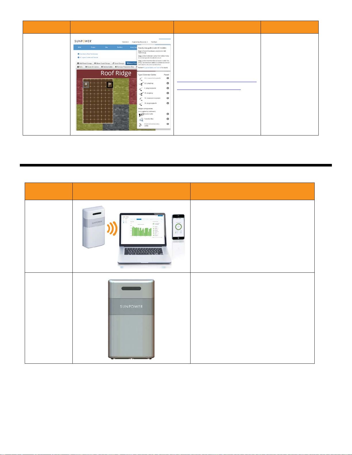
1.3.4 EnergyLink Monitoring Components ............................................................................................................. 15
1.3.5 Torque Values ................................................................................................................................................... 16
1.4 Listings, Classification, and FCC and IC Compliance ............................................................................................... 16
1.4.1 Fire Classification.................................................................................................................................................. 17
1.4.2 FCC and IC Compliance ....................................................................................................................................... 17
1.5 Rapid Shutdown, System Grounding, NEC Compliance, Ground Path, and Disconnects .................................. 17
1.5.1 Rapid Shutdown ................................................................................................................................................... 18
1.5.2 System Grounding ............................................................................................................................................... 18
1.5.3 NEC Compliance ................................................................................................................................................... 19
1.5.4 Ground Path .......................................................................................................................................................... 21
1.5.5 Disconnects ........................................................................................................................................................... 23
1.6 Pre-Installation Checklist ............................................................................................................................................ 26
1.7 Installation Outline ...................................................................................................................................................... 27
1.8 Install InvisiMount and AC Modules .......................................................................................................................... 27
1.8.1 Attachment Span and Rail Cantilever ................................................................................................................ 27
1.8.2 Module Spacing .................................................................................................................................................... 27
1.8.3 Join Rails ................................................................................................................................................................ 28
1.8.4 Install Flashings, Roof Attachments, and Rails ................................................................................................. 29
1.9 Prepare AC Modules and Transition Cable .............................................................................................................. 32
1.9.1 AC Module Clips Overview .................................................................................................................................. 32
Document #518101 RevD 2 SunPower Proprietary

1.9.2 Prepare All Modules ............................................................................................................................................. 33
1.9.2.1 Prepare and Wire the Transition Cable ..................................................................................................... 34
1.9.3 Install Modules ..................................................................................................................................................... 35
1.9.4 Verify Voltage ........................................................................................................................................................ 41
2.0 Install and Commission EnergyLink with PVS5x .................................................................................................... 42
2.1 Safety, Compliance, and Certification ................................................................................................................... 42
2.1.1 Safety Instructions ............................................................................................................................................ 42
2.1.2 FCC Compliance ................................................................................................................................................ 43
2.1.3 Safety Certification ........................................................................................................................................... 43
2.2 Install PVS5x .............................................................................................................................................................. 44
2.2.1 Overview ............................................................................................................................................................ 44
2.2.2 Kit Contents ....................................................................................................................................................... 45
2.2.3 System Connection .......................................................................................................................................... 45
2.2.4 Mount PVS5x ..................................................................................................................................................... 46
2.2.5 Wire PVS5x Power ............................................................................................................................................ 46
2.2.6 Install and Wire Consumption CTs ................................................................................................................. 47
2.2.7 Verify CT Voltage Phases ................................................................................................................................. 48
2.2.8 Connect System Communication ................................................................................................................... 49
2.2.9 Connect PVS5x to the Internet........................................................................................................................ 50
2.3 Commission with PVS Management App ........................................................................................................... 50
2.3.1 Connect to PVS Management App ............................................................................................................... 51
2.3.2 Set Up Communication .................................................................................................................................... 51
2.3.3 Check Firmware ................................................................................................................................................ 52
2.3.4 Discover Devices ............................................................................................................................................... 52
2.3.5 Configure Devices ............................................................................................................................................. 53
2.3.6 Verify Device Operation ................................................................................................................................... 54
2.3.7 Commission Devices ........................................................................................................................................ 55
2.4 Create EnergyLink Home Account for Customer Monitoring ............................................................................ 56
2.5 Replace PVS5x Enclosure Cover ............................................................................................................................. 57
Appendix A: System and Site Checklist and Array Layout Diagram ................................................................................. 58
Document #518101 RevD 3 SunPower Proprietary

A.1 Complete SunPower System and Site Checklist and Create Array Layout Diagram ..................................... 58
Appendix B: Module Removal ............................................................................................................................................... 62
Appendix C: Conductor Selection ......................................................................................................................................... 66
Appendix D: Certificates ......................................................................................................................................................... 69
D.1 Microinverter Revision E: Rapid Shutdown ..................................................................................................... 70
D.2 Microinverter Revision D: Rapid Shutdown .................................................................................................... 77
D.3 Microinverter Revision C: Rapid Shutdown .................................................................................................... 79
D.4 Microinverter First Revision: Rapid Shutdown ............................................................................................... 81
D.5 Type D AC Module .............................................................................................................................................. 83
D.6 Type C AC Module .............................................................................................................................................. 85
D.7 AC Extension Cable ............................................................................................................................................. 86
D.8 InvisiMount System ............................................................................................................................................ 87
D.9 InvisiMount End Clamp ..................................................................................................................................... 88
D.10 PVS5x ................................................................................................................................................................... 89
Appendix E: Quick Start Guide – AC Module Cable Selection ........................................................................................... 90
Appendix F: Technical Specifications .................................................................................................................................... 98
F.1 Type C AC Module Ratings ........................................................................................................................................... 98
F.1.1 X22-360-C-AC..................................................................................................................................................... 98
F.1.2 X21-345-C-AC and X21-335-C-AC .................................................................................................................... 99
F.1.3 X21-335-BLK-C-AC and X20-327-BLK-C-AC .................................................................................................. 100
F.1.4 X20-327-C-AC................................................................................................................................................... 101
F.1.5 E20-327-C-AC and E19-320-BLK-C-AC .......................................................................................................... 102
F.2 Type D AC Module Ratings ........................................................................................................................................ 103
F.2.1 X22-370-D-AC and X22-360-D-AC ................................................................................................................. 103
F.2.2 X21-345-D-AC, X21-335-D-AC, and X20-327-D-AC ...................................................................................... 104
F.2.3 X21-350-D-AC, X21-335-BLK-D-AC, and X20-327-BLK-D-AC ...................................................................... 105
F.2.4 E20-327-D-AC and E19-320-D-AC ................................................................................................................. 106
F.3 PVS5x ........................................................................................................................................................................... 107
F.4 InvisiMount™ ............................................................................................................................................................... 108
F.5 Grid Support, Utility Interactive Inverters, and Regulatory Certification for Type C AC Modules ................... 109
Document #518101 RevD 4 SunPower Proprietary

F.5.1 Grid Profile: IEEE 1547 (2003) ............................................................................................................................ 109
F.5.2 Microinverter Ratings ......................................................................................................................................... 110
F.6 Grid Support, Utility Interactive Inverters, and Regulatory Certification for Type D AC Modules ................... 111
F.6.1 Default Factory Settings for Type D AC Modules: IEEE 1547a-2014 Grid Profile ........................................ 111
F.6.2 Legacy Support Settings: IEEE 1547-2003 Grid Profile ................................................................................... 112
F.6.3 CA Rule 21 Phase 1 Settings for Type D AC Modules ..................................................................................... 114
F.6.4 Reactive Power Capability for Type D AC Modules ......................................................................................... 115
F.6.5 Reactive Power Control Accuracy for Type D AC Modules ............................................................................ 116
F.6.6 Active or Reactive Power Priority for Type D AC Modules ............................................................................. 116
F.6.7 Fixed Power Factor for Type D AC Modules .................................................................................................... 119
F.6.8 Volt/VAr Operation for Type D AC Modules ..................................................................................................... 119
F.6.9 Microinverter Ratings for Type D AC Modules ................................................................................................ 120
Appendix G: AC Module 3-Line Drawing Example ............................................................................................................ 122
Appendix H: Install Rail-Mounted Junction Box ................................................................................................................ 124
Appendix J: Install Rooftop Transition Flashing ................................................................................................................ 126
Appendix K: Attach AC Rail Clips ......................................................................................................................................... 132
Appendix L: Technical Notifications .................................................................................................................................... 133
L.1 PVS5x Site Wiring Check Procedure, T16008 ...................................................................................................... 133
L.2 Installing SunPower AC Modules in High-Noise Environments, T16009......................................................... 136
L.3 Grounding SunPower Equinox Systems, T16013 ............................................................................................... 139
L.4 Rapid Shutdown Compliance for SunPower Equinox Type C AC Modules, T17002 ...................................... 151
L.5 Field Verification of Type C AC Module IEEE 1547 Utility Interactive Trip and Reconnect Functions, T16012
.......................................................................................................................................................................................... 156
L.6 InvisiMount™ and Equinox™ Rail-Mounted J-Box and Rooftop Transition Flashing Specifications, T17003
.......................................................................................................................................................................................... 159
L.7 Update Chrome Version for PVS Management App Commissioning, T16010 ............................................... 161
L.8 Field Verification of Type D AC Module Trip and Reconnect Functions, T17006 ........................................... 163
L.9 Using the PVS5 Management App to Set and Verify the California CPUC Rule 21 Grid Profile on Type D AC
Modules, T17006 ........................................................................................................................................................... 166
L.10 Using the PVS5 Management App to Set and Verify the Xcel Energy of Colorado Grid Profile on Type D
AC Modules, T17008 ...................................................................................................................................................... 173
Document #518101 RevD 5 SunPower Proprietary

L.11 Using the PVS5 Management App to Set and Verify United Illuminating of Connecticut Grid Profiles on
Type D AC Modules, T17010......................................................................................................................................... 179
L.12 Using the PVS5 Management App to Set and Verify New York Utility (NYSEG, RG&E) Grid Profiles on Type
D AC Modules, T17009 .................................................................................................................................................. 185
L.13 PVS Management App Enhanced Functionality for Residential Commissioning, T17013 .......................... 191
L.14 PVS Management App Q2 2017 Updates for Residential Commissioning, T17005 .................................... 196
L.15 Equinox Commissioning Best Practices, T17016 ............................................................................................. 199
Appendix M: PVS5x Installation Instructions and Quick Start Guide ............................................................................. 201
Appendix N: Consumption Meter CT Installation Instructions and Alternate CT Installation Configurations ......... 204
Appendix P: Production Meter CT Installation Instructions ............................................................................................ 207
Appendix Q: EnergyLink PVS5x Knockout Template ........................................................................................................ 208
Document #518101 RevD 6 SunPower Proprietary

1.0 Overview and Scope
This guide describes how to install SunPower Equinox (“the system”). Do not attempt any aspect of the installation
until you have thoroughly read this entire guide. Failure to follow these instructions can result in personal injury or
equipment damage or failure, and may void the system warranty.
The system ships with the following components:
• SunPower AC modules and accessories (including extension cables)
• SunPower InvisiMount™ mounting system
• SunPower EnergyLink™ monitoring system
Document #518101 RevD 7 SunPower Proprietary
1.1 Safety and Warnings for Type C and Type D AC Modules
IMPORTANT SAFETY INSTRUCTIONS – SAVE THESE INSTRUCTIONS!
All personnel must adhere to the following safety procedures when working with the system, including inspection,
installation, operation, service work, repair, and testing. Failure to comply with these precautions or with specific
warnings elsewhere in this guide may violate safety standards of design, warranty, manufacture, and intended use
of the equipment. SunPower assumes no liability for failure to comply with these requirements.
Warning! The installation, adjustment, or repair of a solar system involves the risk of contact
with potentially lethal voltages and currents.
SunPower Type C and Type D AC modules meet all current requirements for rapid shutdown as defined in NEC
690.12 Rapid Shutdown of PV Systems on Buildings. As part of the UL 1741 SA / UL 1741 Listing of the SunPower AC
module product being grid support utility interactive, upon turning off the AC disconnect to de-energize the circuit
to the AC modules on the roof, each AC module output will shut off within 2.0 seconds to comply with IEEE 1547. In
this manner, all wiring leaving each AC module complies with the controlled conductor limits in 690.12.
Follow all applicable laws, including state and federal Occupational Safety and Health Administration (OSHA)
standards when working on any construction project. Always reference the National Fire Protection Agency (NFPA)
70E, Standard for Electrical Safety in the Workplace when performing electrical work.
Perform the installation in accordance with all applicable codes. In addition, reference NEC Articles 250 and 690—as
well as applicable IEC standards—for proper compliance when wiring and grounding the system. All state and
federal guidelines and regulations must be followed as well.
1.1.1 Site Safety
• These installation instructions are for use by qualified personnel only.
• System access is intended for authorized personnel only.
• Only authorized persons may shut down the system or open any system enclosure.
• To reduce the risk of fire, connect only to a dedicated circuit that has overcurrent protection not exceeding the
maximum value stated in the product’s Listing (20 A) in accordance with the NEC, ANSI/NFPA 70. Maximum
dedicated branch circuit overcurrent protection: 20 A.
• The metal components of the module can reach temperatures of approximately 176°F (80°C). Use appropriate
safety procedures when handling modules.
Document #518101 RevD 8 SunPower Proprietary

1.1.2 General Warnings
• Do not attempt to service any portion of the system.
• Do not attempt installation during conditions involving rain, snow, ice, or high winds.
• Do not attempt to install or service the system if you are not a qualified, trained electrician or technician familiar
with power electronic equipment.
• Always wear rubber insulating gloves rated for the appropriate voltage level, and suitable eye and head
protection when working near live electrical equipment.
• Always have a cell phone available for calling emergency personnel.
Changes or modifications not expressly approved by the party responsible for compliance could void the user’s
authority to operate the equipment.
Note: Perform all electrical installations in accordance with any local codes and the National Electrical Code (NEC).
1.2 Installer Responsibilities
Warning! If installing the Equinox system on a metal roof, you must verify with the AHJ whether additional bonding
to the roof is required. Follow the instructions provided by the AHJ and by the roofing manufacturer.
SunPower Equinox is for residential 240 V split single-phase and 208 V three-phase wye double-pole
applications only.
Installers are solely responsible for specific aspects of the system they are installing:
• Selection and verification of design parameters, including wind and snow load and all related aspects.
• Validation of third-party roof attachment design and interoperability, including any stipulations for rail overhang
(cantilever) beyond the last roof attachment (standoff) at the end of a row. Use the SunPower Design Tool
(https://invisimountdesign.us.sunpower.com/login.html
verify spans between roof attachments and maximum cantilever. (Access the Tool by logging into the Portal and
then clicking the Design Tool link.)
• Code compliance and permitting.
• Vetting system compatibility with the installation site and structures.
• Verifying the roof integrity prior to installation.
• Selecting the correct attachment and flashing type for the particular roof.
• Care of the roof during the installation.
) OR the InvisiMount Span Tables document (#524734) to
Document #518101 RevD 9 SunPower Proprietary

1.3 Tools, Equipment, Components, and Torque Values
1.3.1 Tools
The following tools are required to install the system:
Tool Task
10 mm and 15 mm deep sockets Attaching L-foot nuts, mid clamps, end clamps, splices, and splice screws
Assorted screwdrivers and wire
strippers
Caulk gun Installing rooftop transition flashing
CHANNELLOCK® pliers
(or equivalent)
Claw hammer Installing rooftop transition flashing
Cordless drill with electrical
conduit knockout tool or hole saw
Flathead screwdriver Removing and installing rail-mounted J-box cover
Metal saw Cutting rails
Roofing bar Installing rooftop transition flashing
Rubber mallet Removing end clamp
Torque wrench Verifying fastener torque
General electrical wiring
Tightening fittings on rail-mounted J-box and rooftop transition flashing
Drilling holes in rooftop transition flashing and rail-mounted J-box
Utility knife Installing rooftop transition flashing
In addition, ensure that you have all necessary tools to install your chosen roof attachments!
1.3.2 Equipment
All applicable personal protective equipment (PPE) is always required, including:
• Fall protection
• Gloves
• Safety glasses
Document #518101 RevD 10 SunPower Proprietary
• Hard hat
• Appropriate footwear
• All appropriate electrical PPE
1.3.3 Components
Important! SunPower requires that you use a torque wrench—not an impact driver—to enforce consistent fastener
tightness and thereby ensure safe, high-quality installations.
Component Definition Tool and Torque
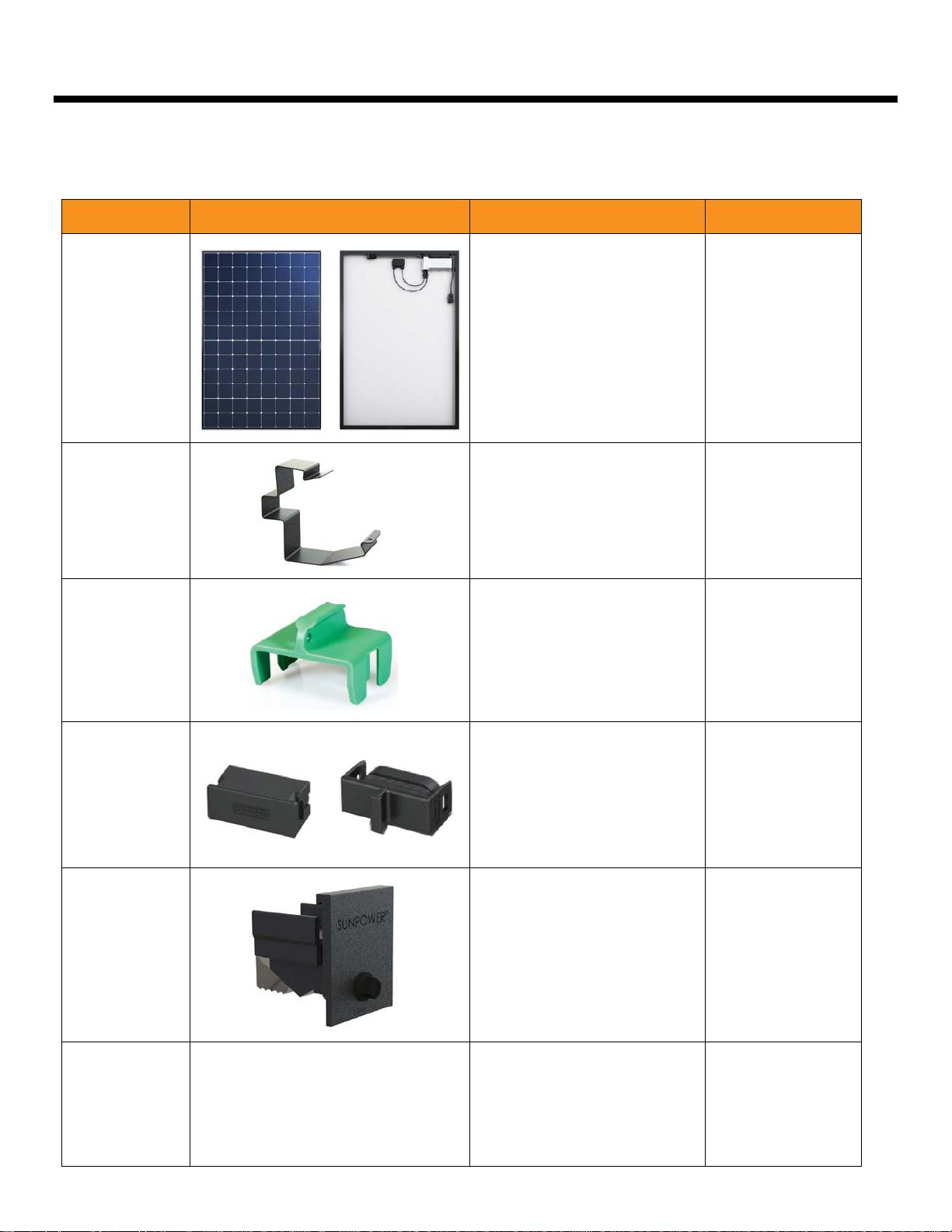
AC module
AC rail clip
(optional)
Disconnect
tool
An assembly that includes a
photovoltaic glass panel, a
microinverter, a robust frame,
and two electrical leads.
Attaches to rails and helps to
support a single AC cable
above the lower edge of the
rails.
Unlocks AC cable plug–
receptacle pairs after they
have been connected.
See Mid clamp
and
End clamp
n/a
n/a
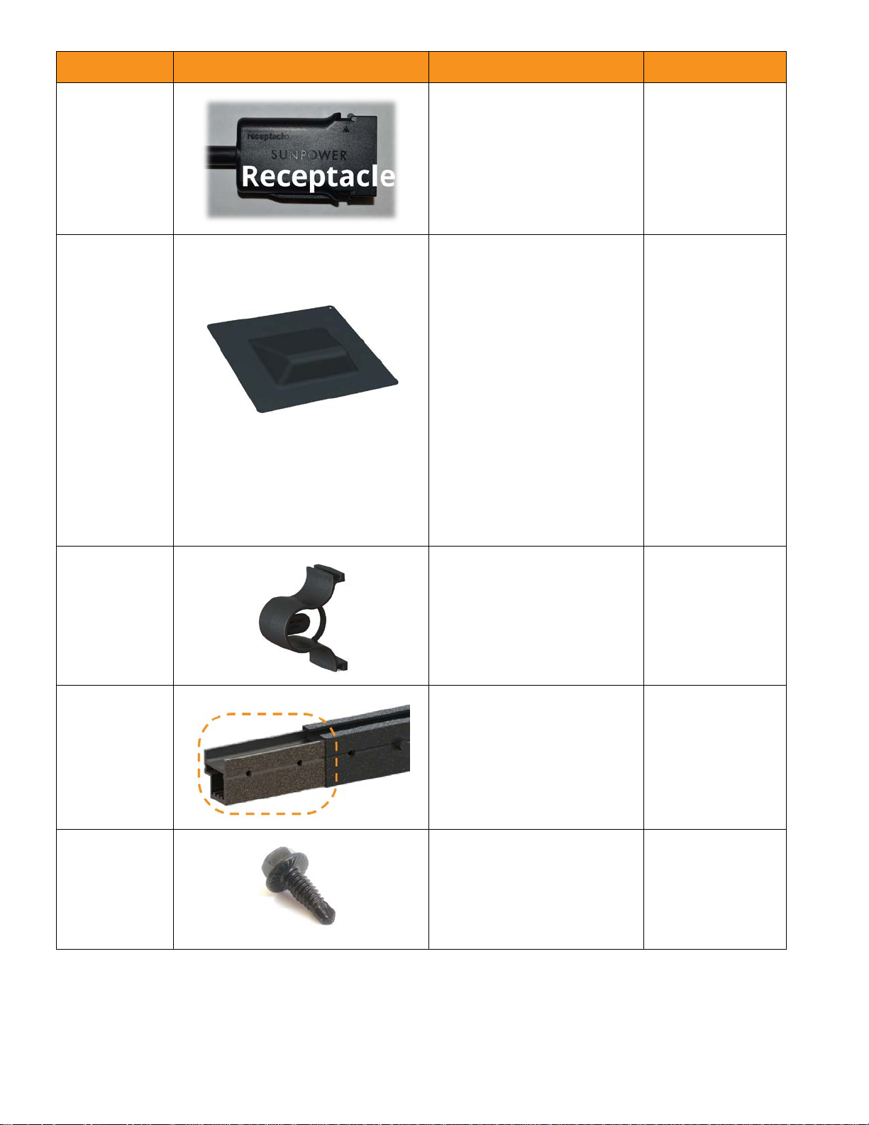
End cap
End clamp
Extension
cable
Fits into the plug or the
receptacle of the last module
in a circuit.
Note: The caps are different
for plugs and receptacles.
Module-to-rail fastener that
fits into the end of a rail,
clamps to secure each of the
endmost modules in a given
row, and provides equipment
bonding from modules to the
rail.
Premanufactured AC cables
that enable connecting of
non-adjacent AC modules.
n/a
• 10 mm deep
socket
• 85 +5/−0 in-lb
(9.6 N-m)
n/a
(See Disconnect
tool)
Component Definition Tool and Torque
Extension cables contain
identical conductor
composition as the built-in AC
module cables (threeconductor, 12 AWG, type TCER), and are available in
several lengths, with plug–
plug, receptacle–receptacle,
or plug–receptacle connector
pairs. Cables are UL
Recognized and conform to
UL 6703 and UL 9703.
The cable outside diameter is
11.2 mm (0.44 in).
Flashing
L-foot
Thin sections of material that
n/a
are installed between the roof
substrate and any rooftop
penetration in order to
prevent water from
penetrating the roof.
Note: Shown with with
SunModo’s roof attachment
and L-foot for composition
shingle roofs; and with their
tile hook mount—separate
components all available
from SunPower.
L-shaped bracket that
provides interface between
the roof attachment and the
rail; typically made of
stainless steel or aluminum.
Refer to the roof
attachment
manufacturer
guidance. If using a
roof attachment
other than L-feet,
refer to that
attachment
manufacturer
guidance.
Document #518101 RevD 12 SunPower Proprietary

Component Definition Tool and Torque
L-foot bolt
and nut
Mid clamp
Plug
Hardware that secures the
rail to the L-foot (or to the
chosen roof attachement):
Bolt: M10-1.5 × 25 mm
• 10 mm deep
socket
• 375 +20/−0 in-lb
(42 +2/−0 N-m)
DIN 933 SS304
Nut: M10-1.5 DIN 6923
SS304
Module-to-rail fastener that
attaches in the top rail
channel; secures module
frames; and provides
equipment bonding between
modules and the rail.
The AC cable connector end
• 10 mm deep
socket
• 85 +5/−0 in-lb
(9.6 N-m)
n/a
that has tabs on either side.
Note: SunPower AC cable
connectors are an approved
means of disconnect.
Rail
Rail-mounted
J-box
(optional)
Extruded aluminum
component that attaches to
the L-feet and supports
clamped modules. Each rail
section is 10′ 9″ (3.28 m) long.
For the nuts that fit
onto the bolts
which slide into
the side channel:
• 15 mm deep
socket
• 375 +20/−0 in-lb
(42 +2/−0 N-m)
Junctions array circuits on the
roof; attaches to a rail with no
tools.
For cover screws:
• flathead
screwdriver
• 16 in-lb
(1.8 N-m)
Document #518101 RevD 13 SunPower Proprietary
Component Definition Tool and Torque
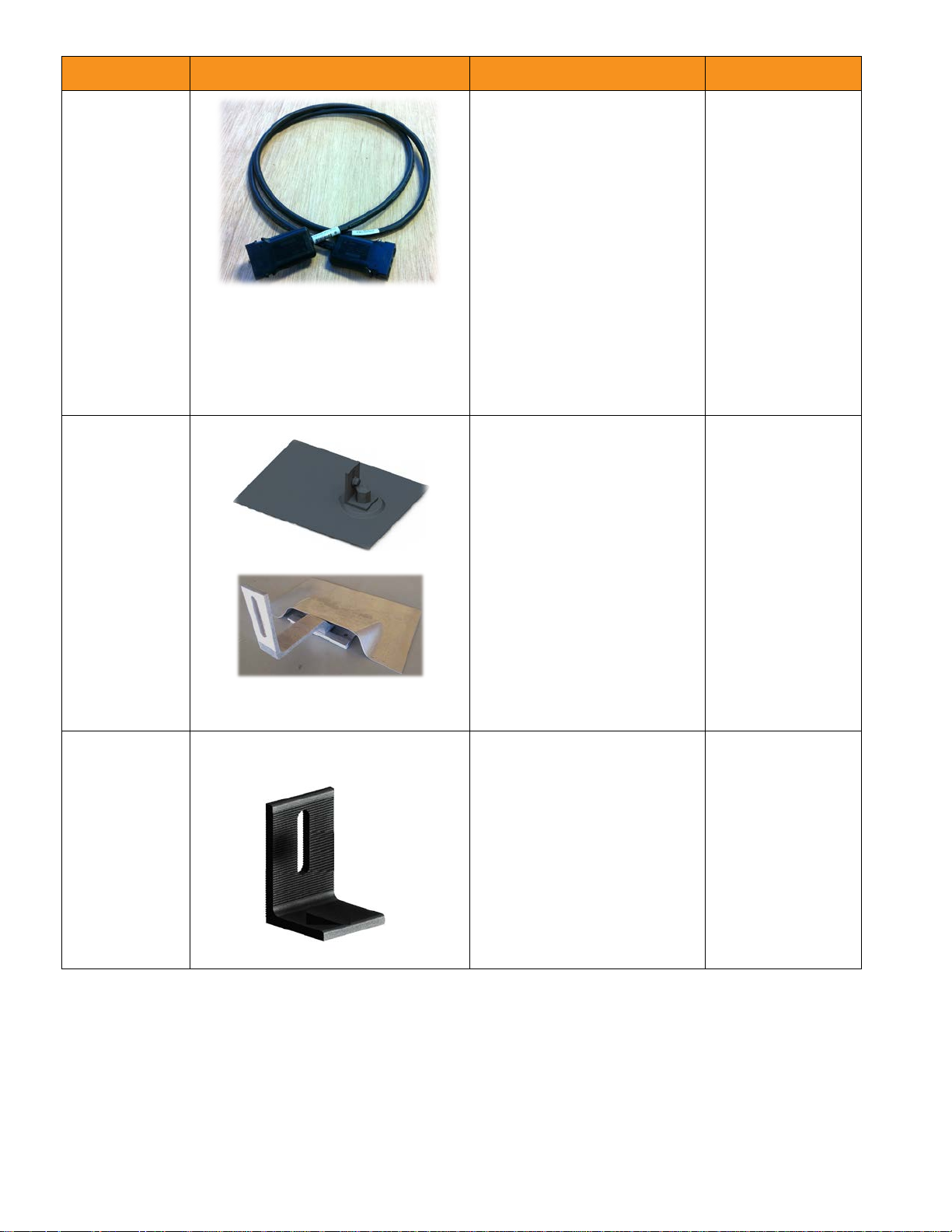
Receptacle
Rooftop
transition
flashing
(optional)
The AC cable connector end
n/a
that does not have tabs.
Note: SunPower AC cable
connectors are an approved
means of disconnect.
Installs on the rooftop and
enables wiring to transition
• Utility knife
• Roofing bar
between the rooftop and the
building interior.
Note: If you are not using a
transition box such as a
SolaDeck™ enclosure, use the
rooftop transition flashing
along with the rail-mounted Jbox (or attic-mounted J-box)
to transition between building
wiring and array wiring.
• Caulk gun
• Claw hammer
• Drill with
conduit
knockout tool
or hole saw
• Two
CHANNELLOCK
tongue &
groove pliers
(or equivalent)
Row-to-row
(R2R) spacer
Splice
Splice screw
Plastic spacer that snaps into
n/a
the exterior module frame
and uniformly enforces the
distance between rows of
adjacent modules.
Extruded aluminum
See Splice screw
connector that, along with
splice screws, joins two rails.
Black oxide coated stainless
steel fastener that, in
conjunction with a splice,
attaches two sections of rail
together.
• 10 mm deep
socket
• 40 +5/−0 in-lb
(4.5 N-m)
Document #518101 RevD 14 SunPower Proprietary
Component Definition Tool and Torque
Enables complete array
design online as well as
providing the bill of materials
for the array.
SunPower
Design Tool
invisimountdesign.us.sunpow
er.com/bom/index.html
Access the Tool from the
Portal.
1.3.4 EnergyLink Monitoring Components
Term Definition
n/a
EnergyLink™
Monitoring
PVS5x
SunPower’s proprietary monitoring solution
that enables partners and customers to
easily understand and view both system
production and home energy consumption.
PV Supervisor 5x; commnicates with the AC
modules to monitor system performance
and transmit data to SunPower servers.
Document #518101 RevD 15 SunPower Proprietary

1.3.5 Torque Values
Fastener Final Torque
End clamp
85 +5/−0 in-lb (9.6 N-m)
Mid clamp
L-foot to rail nuts 375 +20/−0 in-lb (42 +2/−0 N-m)
Rail splice screws 40 in-lb (4.5 N-m)
(This torque value is achieved by 1/3 turn of the screw after the screw face
has contacted the rail face. After tightening in this manner, verify the
applied torque with a torque wrench.)
L-foot to roof
attachment
Refer to the roof attachment manufacturer’s documentation (included in
the roof attachment box). If using a roof attachment other than L-feet, refer
to that attachment manufacturer’s included documentation.
1.4 Listings, Classification, and FCC and IC Compliance
Important! This guide assumes you are installing AC modules on InvisiMount as part of a SunPower Equinox
system; if you are installing DC modules on InvisiMount, do not use this guide—instead use the InvisiMount
Residential Mounting System Installation Guide.
The InvisiMount system is UL 2703 Listed. For the most recent information, refer to the UL database
http://database.ul.com/QHYZ.E478330
the following SunPower Type C and Type D AC modules:
• SPR-X22-360-C-AC
• SPR-X21-345-C-AC
• SPR-X21-335-C-AC
• SPR-X21-335-BLK-C-AC
. At the time of publication of this guide (#518101 RevD), the Listing includes
• SPR-X20-327-BLK-C-AC
• SPR-X20-327-C-AC
• SPR-E20-327-C-AC
• SPR-E19-320-C-AC
• SPR-X22-370-D-AC
• SPR-X22-360-D-AC
• SPR-X21-350-BLK-D-AC
• SPR-X21-345-D-AC
• SPR-X21-335-BLK-D-AC
Document #518101 RevD 16 SunPower Proprietary
• SPR-X21-335-D-AC
• SPR-X20-327-BLK-D-AC
• SPR-X20-327-D-AC
• SPR-E20-327-D-AC
• SPR-E19-320-D-AC

Grounding from the module to the rail is accomplished through both the mid clamp and the end clamp. The
InvisiMount Listing also includes the following components, which have been evaluated for both mounting and
bonding in accordance with UL 2703:
• end clamp
• mid clamp (UL 2703 Listing is also valid if a mid clamp is used as an alternative to an end clamp)
• rail
• splice and splice screw
• L-foot
1.4.1 Fire Classification
• The maximum distance between the roof deck and the bottom of the module frame is 3” (7.6 cm).
• In order to maintain the system classification, this assembly must be mounted over a fire resistant roof covering
for the application.
• The system achieves a Class A fire rating when installed with modules having a Type 2 fire classification.
• The system achieves a Class A fire rating when installed in the manner specified in these instructions.
• The system was evaluated for use on roofs having a pitch ≥ 2″/foot (greater than or equal to 2:12).
1.4.2 FCC and IC Compliance
Note: For PVS5x FCC and compliance information, refer to Section 2.1.2.
The microinverter built into each AC module has been tested and fully complies with Federal Communication
Commission (FCC) Part 15 Class B for digital devices; as well as Industry Canada (IC) Interference-Causing Equipment
Standard ICES-003 Class B. The regulations in FCC Part 15 are designed to provide reasonable protection against
harmful interference in a residential installation. This equipment generates, uses, and can radiate radio frequency
energy, and, if not installed and used in accordance with the instructions, may cause harmful interference to radio
communications.
1.5 Rapid Shutdown, System Grounding, NEC
Compliance, Ground Path, and Disconnects
Warning! If installing the Equinox system on a metal roof, you must verify with the AHJ whether additional bonding
to the roof is required. Follow the instructions provided by the AHJ and by the roofing manufacturer.
This section is intended to provide a well-rounded understanding of all aspects of rapid shutdown, grounding,
disconnect requirements, and NEC compliance for SunPower Equinox.
Document #518101 RevD
17 SunPower Proprietary

1.5.1 Rapid Shutdown
SunPower Type C and Type D AC modules meet all 2014 and 2017 NEC requirements for rapid shutdown as defined
in NEC 690.12 Rapid Shutdown of PV Systems on Buildings. As part of the UL 1741 SA / UL 1741 Listing of the
SunPower AC module product being grid support utility interactive, upon turning off the AC disconnect to deenergize the circuit to the AC modules on the roof, each AC module output will shut off within 2.0 seconds to
comply with IEEE 1547. In this manner, all wiring leaving each AC module complies with the controlled conductor
limits in 690.12.
Refer to Section D.1, D.2, and D.3 for the Rapid Shutdown Certificates of Compliance.
1.5.2 System Grounding
The InvisiMount system is Listed to UL 2703 for integrated grounding; SunPower AC modules are an
electrical bonding component and are Listed to UL 1741 SA / UL 1741; thus no additional grounding
hardware, lugs, or copper wire are required on the roof.
• The SunPower AC module is one of the components that electrically bonds all of the metallic non-current
carrying components in the system, and is Listed to UL 1741 SA (Type D AC modules) / UL 1741 (Type C AC
modules).
• Only AC equipment grounding requirements apply when installing Listed AC modules to racking that is Listed to
UL 2703—neither DC system grounding requirements (GEC) nor DC equipment grounding requirements (EGC) apply.
• The equipment grounding conductor (EGC) that is built into and Listed with the AC module cable system is sized
appropriately and meets all of the AC equipment grounding requirements for the system.
• The AC dedicated branch circuit wiring from the distribution panel to the array must include an equipment
grounding conductor (EGC) in the same raceway or cable as the AC circuit conductors. This EGC must be
connected to the green conductor of the transition cable, which is part of the AC module cable system.
• The AC module connectors (plugs and receptacles) are rated for disconnect, both under load and not under load.
• A grounding electrode conductor (GEC) for the module or array is not required because the DC power is internal
to the AC module. The existing AC GEC at the premises or structure utility service serves as the NEC-required
GEC for the AC module system.
• The AC cable grounding path has been tested by UL, and its electrical continuity from the AC cable ground pin to
the module frame has been evaluated as part of the AC module Listing.
• The AC module interconnecting cable system provides an internal EGC for grounding the AC modules.
• Neither the AC modules nor the array require a GEC. The AC module must be connected to a dedicated AC
branch circuit with an appropriately sized equipment grounding conductor (EGC). The EGC must be connected to
a grounding electrode using the existing premises wiring system, typically originating at the building service
entrance or service panel.
• The AC interconnecting cable system attached to each module’s microinverter is fully insulated and includes an
internal EGC. The grounding pin is longer than the others in the plug, providing a “first-make, last-break”
connection sequence.
• The green conductor in the AC cable is connected to the EGC from the utility dedicated branch circuit (“the
building ground”).
Document #518101 RevD
18 SunPower Proprietary

• The AC ground wire inside the microinverter terminates on the microinverter chassis with a bolted connection,
and is environmentally sealed; and the microinverter chassis is bonded to the module frame with stainless steel
hardware to provide ground continuity to the module frame.
• If a module is removed from a circuit (for service or replacement, for example), remember that the AC
module cable system is daisy-chained and that therefore you must first disconnect all power and then
install a temporary EGC to bridge the gap by inserting an AC extension cable or other means, in order to
maintain effective ground continuity to subsequent modules. Disconnecting a module from the circuit
removes voltage and might also remove ground from the other downstream modules in the circuit.
Extreme care should be taken to ensure that no other energized sources are adjacent to these
ungrounded modules. Refer to Appendix B.
Each SunPower AC module includes a factory-integrated microinverter (MI) that does not require a neutral
wire to be connected to it for operation or for compliance with IEEE 1547. Power produced is conducted on the
L1–L2 240 VAC or 208 wye VAC grid connection. Utility interactive functions in the MI circuitry have been evaluated
to IEEE 1547, and use the ground wire instead of the neutral to determine grid values. This functionality is part of its
UL Listing.
This product must only be connected to a single-phase system (L–L) of a premises with the neutral (N)
bonded to ground at the service entrance per code. (The MI does not reference the N to ground internally,
therefore this reference must be accomplished only at the service entrance.) Ensure that the installation site has a
high-quality N-to-ground reference at the service. The MI determines L–N voltages based on measuring internally
from L to the MI chassis, which is connected to the EGC.
1.5.3 NEC Compliance
The following are the grounding-related NEC Articles and their applicability to SunPower Equinox:
The following are the grounding-related NEC Articles and their applicability to SunPower Equinox:
• 690.11 pertains to DC arc fault circuit protection and is not applicable to SunPower Equinox.
• 690.12 requires rapid shutdown; SunPower AC modules (the heart of Equinox) meet all requirements for rapid
shutdown as defined in NEC 690.12 Rapid Shutdown of PV Systems on Buildings. As part of the UL 1741 SA / UL
1741 Listing of the SunPower AC module product being utility interactive, upon turning off the AC disconnect to
de-energize the circuit to the AC modules on the roof, each AC module output will shut off within 2.0 seconds to
comply with IEEE 1547. In this manner, all wiring leaving each AC module complies with the controlled conductor
limits in 690.12.
• 690.31(D) requires that the equipment be grounded using an equipment grounding conductor (EGC) inside the
AC module cable. Equinox AC cables are compliant because they do include this EGC.
• 690.41 does not apply to AC modules. This section applies to the grounding of DC circuits (e.g., positively
grounded PV systems). As such, it applies to photovoltaic source circuits or photovoltaic output circuits. Per
690.6, the output of an AC module is an inverter output circuit and therefore the requirements of 690 that
pertain to photovoltaic source circuits or output circuits do not apply to AC modules.
• 690.42 does not apply to AC modules for the same reasons 690.41 does not.
• 690.43 covers equipment grounding, which is the only required type of grounding for an AC module. SunPower
Equinox fully complies with the relevant portions of 690.43:
Document #518101 RevD
19 SunPower Proprietary

o 690.43(A) – SunPower Equinox is grounded when installed according to the instructions and connected to
an equipment grounding conductor bonded to the premises grounding electrode system.
o 690.43(B) – SunPower Equinox requires the installation of an equipment grounding conductor between the
array and other equipment (typically originating at the rooftop junction box and terminating at the
grounding busbar or terminal in the main service panel).
o 690.43(C) – InvisiMount end clamps and mid clamps are Listed and identified for bonding module frames to
rails.
o 690.43(D) – InvisiMount end clamps and mid clamps are Listed and identified for bonding module frames to
rails.
o 690.43(E) – InvisiMount mid clamps are identified for the purpose of grounding modules.
o 690.43(F) – The integrated AC module cable and AC module extension cables do include an equipment
grounding conductor.
• 690.45 specifies that EGCs should be sized based on 250.122. Equinox meets this requirement by including a 12
AWG equipment grounding conductor. The EGC in every AC module cable is 12 AWG. The maximum overcurrent
protection for an AC module circuit is 20 A. The minimum EGC size based on the table at 250.122 is 12 AWG. If
multiple circuits are routed with a single EGC for the array, 250.122(C) permits the installer to use 12 AWG for the
combined EGC.
• 690.46 modifies 690.45 when the EGC is not protected within a raceway, and does not apply to SunPower
Equinox. It modifies 690.45 by requiring a larger conductor when the EGC is not routed with circuit conductors
and installed outside of a raceway. But SunPower Equinox does comply with 690.31(D) which requires that the
EGC be contained within the cable assembly. 690.46 was inserted into the Code to prevent installers from using
small conductors such as 14, 12, or 10 AWG to ground rails in systems having no integrated grounding.
• 690.47 does not apply to AC modules:
o 690.47(A) does not apply to Equinox because the AC “system” was already existing on the premises (already
installed per Article 250 of the code) and the AC module system connects to the load side of this service.
Installing AC modules constitutes the installation of new “equipment” on an existing AC system. As such, the
existing system already has a grounding electrode system, and the only requirement is to connect the new
equipment to that system.
o 690.47(B) applies to DC systems; it does not apply to AC modules, and does not apply to SunPower Equinox.
This section pertains only to DC systems in which a photovoltaic source circuit would be either grounded or
ungrounded; but 690.6 exempts AC modules from requirements pertaining to photovoltaic source circuits.
Code language states that the intention of an auxiliary grounding electrode can be achieved through a
properly installed EGC back to the premises grounding electrode. SunPower Equinox meets this intention
for rooftop arrays by using the integrated grounding system along with a properly sized and installed EGC.
o 690.47(C) does not apply to SunPower Equinox for the same reasons that 690.47(A) and 690.47(B) do not
apply.
o 690.47(D) only provides guidance for a “dc grounding electrode conductor” and does not apply to SunPower
Equinox on residential rooftops where there is an existing adequate premises grounding electrode system.
In most cases (99%), the premises wiring electrode eliminates the need for an additional array grounding
electrode (Exception No. 2) and the equipment grounding conductor connected to the grounding busbar or
terminal in the main service panel is sufficient for connecting the metallic surfaces of the array to ground.
• 690.48 addresses module removal. When an AC module is removed from a SunPower Equinox system, it
interrupts the circuit and equipment grounding connection between modules. This can leave the equipment
Document #518101 RevD
20 SunPower Proprietary

ungrounded if it is not returned to service. Upon a module’s removal, the modules downstream of the removed
module are reconnected using an AC module extension cable to bridge the gap, which re-establishes the
equipment grounding connection.
• 690.49 does not apply to Equinox because it refers to photovoltaic source and output circuit grounded
conductors.
• 690.50 does not apply to Equinox because equipment bonding jumpers are not used.
• 690.52 requires that the AC module be marked with identification of its leads and that it provide five specific
ratings. SunPower AC modules are so marked and are thus fully compliant.
• 705.12(D)(6) previously required AC arc fault protection on the output of AC modules if the modules use rooftop
cables that are not in a raceway; however, 705.12(D)(6) has been deleted by a tentative interim amendment (TIA)
to the 2014 NEC, and has been deleted in the 2017 NEC:
www.nfpa.org/codes-and-standards/all-codes-and-standards/list-of-codes-andstandards?mode=code&code=70&tab=editions
www.nfpa.org/assets/files/AboutTheCodes/70/TIA_70_14_11.pdf
AFCI on the AC side is not required and is not included with SunPower AC modules.
Section 4.1 of the SunPower AC Module Safety and Installation Instructions (#514744) states:
As a Listed product, “SunPower AC modules shall be installed and used in accordance with any instructions included in
the listing or labeling” (NEC 110.3(B)). In addition, SunPower AC modules “shall be grounded using the integrated
equipment grounding conductor...no additional grounding conductor attachment to the AC module is required.”
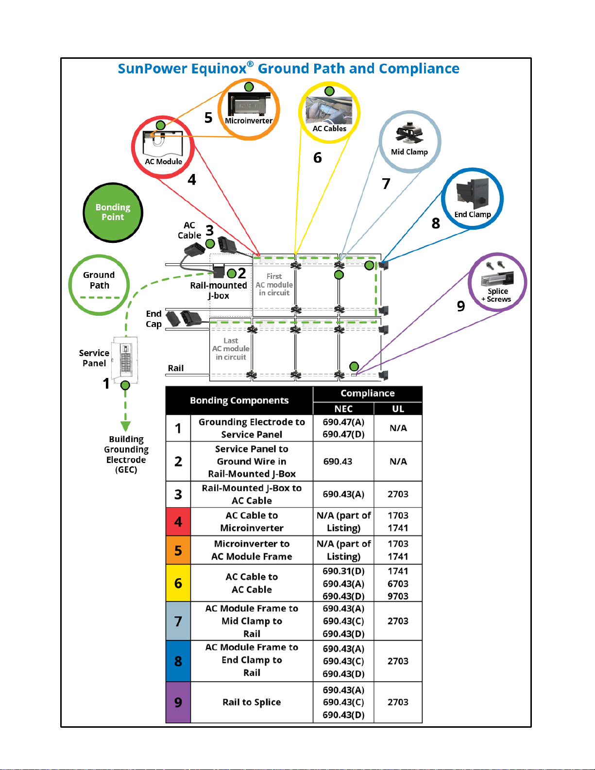
1.5.4 Ground Path
The system features:
• integrated module-to-rail as well as module-to-module bonding (achieved through the mid clamp and end
clamp).
• integrated rail-to-rail bonding (achieved through the self-drilling splice screws and the splice).
• system bonding achieved through the equipment ground conductor (EGC).
The following diagram illustrates the key grounding and bonding aspects of the system:
• the system ground path
• each component
• each bonding point
• the applicable NEC and UL references
Document #518101 RevD
21 SunPower Proprietary
Document #518101 RevD
22 SunPower Proprietary
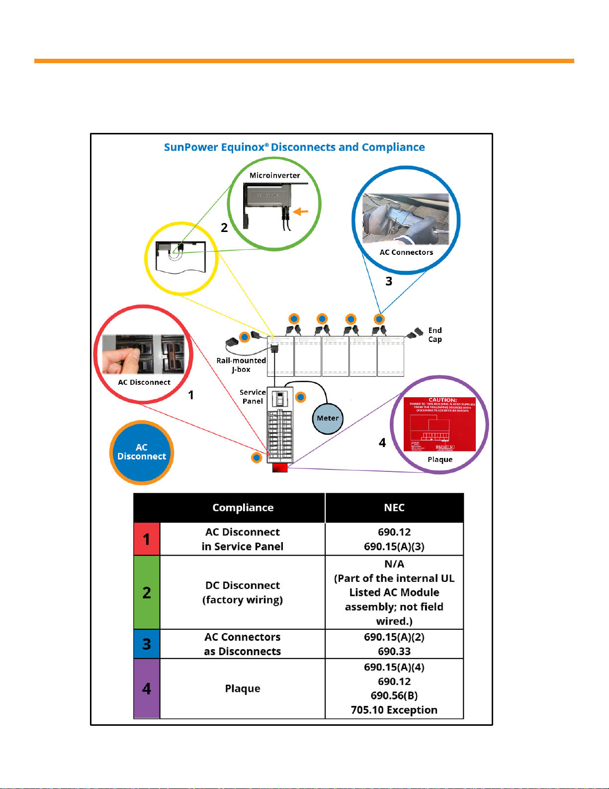
1.5.5 Disconnects
The following diagram and text illustrate NEC conformance to each of the relevant disconnect aspects of the
system, including the use of SunPower AC module connectors as disconnects.
Document #518101 RevD
23 SunPower Proprietary

SunPower AC modules require the use of cables and connectors that are UL Recognized and that conform to UL
6703 and UL 9703; the provided SunPower AC extension cables and their built-in connectors meet these
requirements, contain an EGC, and are rated at 20 A and 600 V. In addition, the AC module connectors are rated
for disconnect under load.
Applicable NEC context for AHJs evaluating a roof-mounted AC module array
AC modules must be installed per 690.6:
• 690.6(A): DC photovoltaic source circuits don’t apply to AC modules.
• 690.6(B): The output of an AC module shall be considered an inverter output circuit.
• 690.15(A): With respect to the AC output, an AC module installed on a roof is the equivalent of an inverter in a
not readily accessible location.
• 690.15(A)(2): An AC disconnecting means must be within sight of (or in) an inverter; the AC cable connectors can
function as this disconnecting means as per 690.17 Exception; if and only if the connectors are rated for
disconnect as per 690.33; the connectors on the SunPower AC cables (module and extension) are fully compliant
in all these respects.
SunPower Equinox fully complies with NEC disconnect requirements
690.15(A) requires utility interactive inverters in not readily accessible locations to comply with certain
provisions. Because the output of an AC module is to be “considered an inverter output circuit,” it’s reasonable to
apply as much of 690.15 as applies to inverter output circuits, but not photovoltaic source circuits:
• 690.15(A)(1) does not apply because it only applies to photovoltaic source or photovoltaic output circuits.
• 690.15(A)(2) does apply and mandates that an AC disconnecting means shall be mounted within sight of or
within the inverter.
• 690.15(A)(3) does apply and mandates that an additional, readily accessible disconnecting means is required.
How does SunPower Equinox comply with 690.15(A)(2)?
The module-integrated AC module cable connectors (plugs and receptacles) are the AC disconnecting means,
because 690.17(E) Exception states that:
A connector shall be permitted to be used as an ac or dc disconnecting means, provided that it complies with the
requirements of 690.33 and is listed and identified for use with specific equipment.
How do the Equinox AC module connectors comply with 690.17(E) Exception?
Our connectors are UL Recognized for use with all of the module models listed in Section 1.4.
• 690.33(A): Equinox connectors are polarized and noninterchangable with other receptacles on the premises.
• 690.33(B): Equinox connectors are guarded (are touch-safe).
• 690.33(C): Equinox connectors are of the locking type.
• 690.33(D): Equinox connectors are first-make, last-break for the internal equipment grounding conductor (EGC).
• 690.33(E): Equinox connectors are rated for interrupting current (load break) and are suitable as disconnects.
How do Equinox AC modules comply with 690.15(A)(3)?
The breaker in the readily accessible main service panel—or any other AC disconnect in the system—can be
considered the readily accessible disconnecting means. But if the circuit runs through the house (as it will in many
installations), it would seem then that SunPower AC modules must also comply with 690.31(E).
Document #518101 RevD
24 SunPower Proprietary

But while 690.31(E) does have special provisions for photovoltaic source and output circuits inside a building, a
SunPower AC module is an inverter output circuit, and the provisions applying to photovoltaic source and output
circuits thus do not apply to AC modules. (The clear intent of the code is to provide special protections for DC
circuits, but there are no special provisions for AC circuits.)
Summary
In a SunPower Equinox system the required AC disconnect on the roof is the AC connector pair (a plug and a
receptacle); the AC disconnect on the ground is the AC breaker in the service panel (or the external switch, if used).
The integrated grounding solution incorporated into SunPower Equinox is 100% end-of-line tested and Listed by UL.
Document #518101 RevD
25 SunPower Proprietary
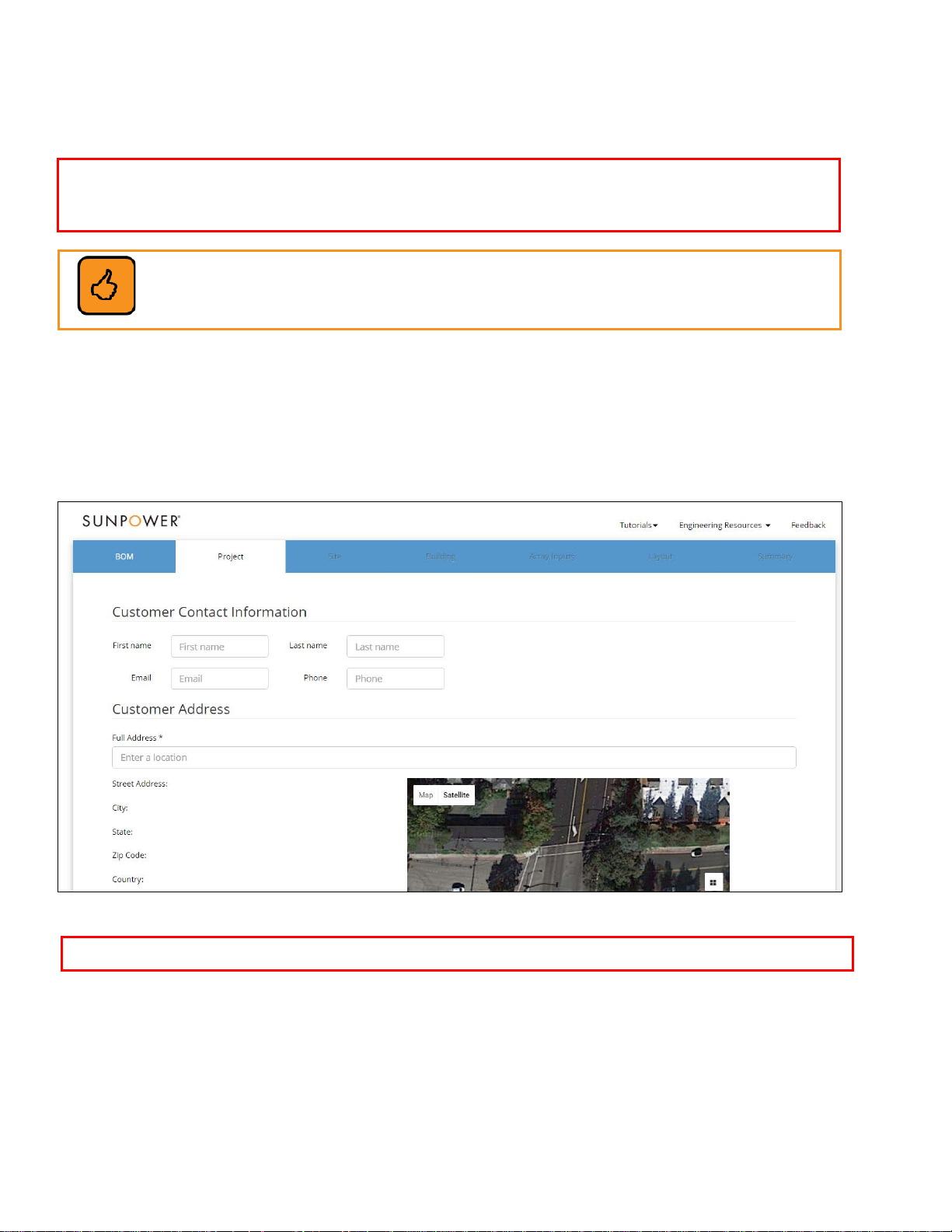
1.6 Pre-Installation Checklist
Important! SunPower strongly recommends using the online SunPower Design Tool (accessed
from the Portal) to design your arrays and determine the accompanying bill of materials (BOM).
In addition, always refer to the InvisiMount Span Tables document (#524734).
Best Practice: To help save time, ensure a safe and high-quality installation, and avoid any
confusion about the system details, fill out the SunPower System and Site Checklist
(located in Appendix A of this guide) as you build the array and install the system.
Your array should be fully designed and all required permitting obtained before you begin installing the system.
Use the SunPower Design Tool OR the InvisiMount Span Tables document (#524734) to determine the actual span
between attachments for a given system.
Designers can access the Tool by logging into the Portal and then clicking the Design Tool link. The Tool yields all
the racking–specific structural calculations that can then be provided to the AHJ and that are typically part
of the permitting process.
SunPower Design Tool
Ensure that you bring the resulting PDF file to the site—its cabling diagram offers you significant time savings!
Document #518101 RevD
26 SunPower Proprietary

1.7 Installation Outline
1. Mark the rooftop for penetrations.
2. Install the flashings (if part of the attachment solution for your roof type) and the roof attachments.
3. Install the InvisiMount system and the AC modules.
4. Install the EnergyLink™ hardware (PV Supervisor 5x) monitoring system and set up EnergyLink.
5. Commission the system.
1.8 Install InvisiMount and AC Modules
Important! The maximum number of modules for a single 20 A circuit in a 240 V single-phase system is 12.
These instructions describe attaching the rails parallel to the roof peak (“E–W”). The rail section length is 10′ 9″ (3.28
m) and is optimized to accommodate three modules in portrait position; or two modules in landscape.
For composition shingle roofs, it is acceptable to attach InvisiMount to either the rafters or the roof deck. SunPower
recommends the following attachments which have been integrated into the SunPower Design Tool for easy design
and permitting:
• For rafter attachment: SunModo K10068-BK8 (SunPower #508329)
• For deck attachment SunModo K10068-BK7 (SunPower #508330)
Instructions for installing the above attachments can be found here:
sunmodo.com/wp-content/uploads/2015/04/D10011-V002-Guide-EZ-Roof-Mount.pdf
For curved and flat tile roofs, SunPower recommends Quick Mount PV QMHSS Quick Hook (SunPower #510083),
which is also integrated into the SunPower Design Tool. Installation instructions can be found here:
www.quickmountpv.com/support/videos/qhk-quick-install.html
Important! Hook attachments may be attached to the rafters only—not to the roof deck.
1.8.1 Attachment Span and Rail Cantilever
The maximum span (distance between roof attachments) is 8′ (2.4 m). The maximum rail overhang length
(cantilever) beyond a rail’s endmost attachment is 24″ (61 cm). This distance may be less—but never more—based on
site-specific conditions. Use the SunPower Design Tool (https://invisimountdesign.us.sunpower.com/login.html
the InvisiMount Span Tables document (#524734) to verify spans between roof attachments and maximum cantilever
for your particular site.
Access the Tool by logging into the Portal and then clicking the Design Tool link.
) OR
Note: A spliced rail does not require any special allowance for span or cantilever.
1.8.2 Module Spacing
• Adjacent modules that share a mid clamp (side to side; L–R in a typical row): 0.8” (20 mm), governed and
enforced when the mid clamps are installed.
• Adjacent rows (an upper and a lower row in a typical array): 13/16” (20 mm), governed and enforced by the row-
to-row (R2R) spacers when used (refer to Fig. 23); minimum is 1/4” (6.5 mm).
Document #518101 RevD
27 SunPower Proprietary
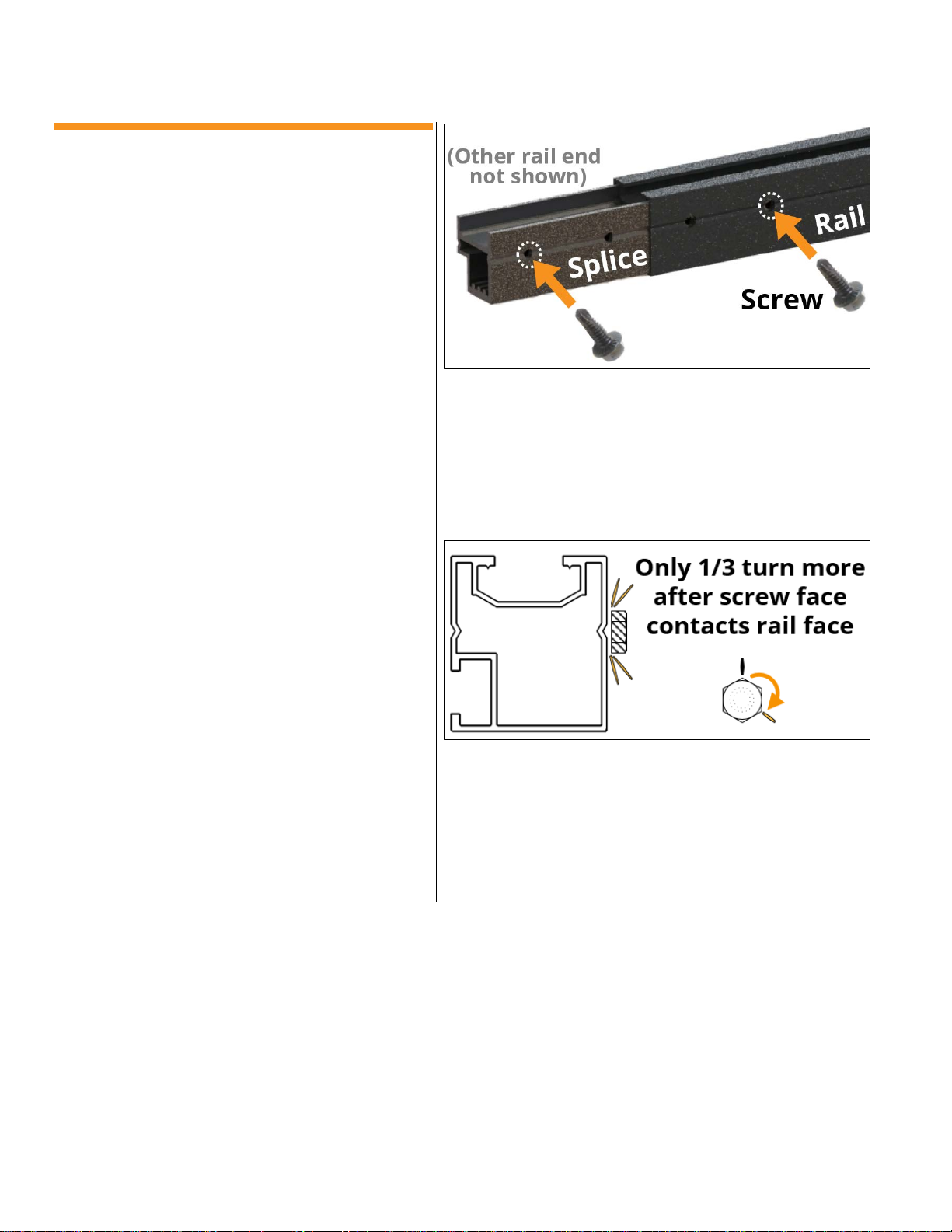
1.8.3 Join Rails
The rails and the splices have pre-drilled holes for
the splice screws: four in the splice and two in each
rail end. You install one screw per rail section, in the
hole furthest from the rail end (Fig. 1).
Important! The splice is an integral part of the
ground path. There must be no interference
between the splice screws and the L-feet.
1. Fit a splice halfway into a rail end, align the
splice holes with the rail holes, secure the
components so that they will not move, and
then drive a splice screw through the aligned
hole that is furthest from the rail end, stopping
1/3 turn after the screw face has contacted the
rail face (Fig. 2). This method provides 40 +5/−0
in-lb (4.5 N-m) of torque. Use a torque wrench to
verify and (if necessary) apply final torque to
each screw.
2. Splice screws are single use. If a screw becomes
dull or prevents smooth, consistent penetration
of the splice, use a new screw in the original
hole. If a screw breaks, use the other existing
hole—do not reuse the original hole, and do not
drill additional holes.
3. Fit the second rail all the way onto the splice
protruding from the first rail, align the
respective holes, and install the second screw.
The rail holes and splice holes must be aligned;
the rail ends are not required to be in contact
with each other. The maximum distance
between a spliced rail pair is 1/4″ (6.4 mm).
Fig. 1
Fig. 2
Document #518101 RevD
28 SunPower Proprietary
1.8.4 Install Flashings,
Roof Attachments,
and Rails
1. Define the installation zone and array layout on
the rooftop and mark it for penetrations as
necessary.
2. Referring to the manufacturer guidance for both
the flashing (if appropriate for the roof type) and
for your chosen roof attachment:
a. Install the flashings and the roof
attachments.
b. According to the roof attachment
manufacturer guidance, attach an L-foot to
each of the roof attachments. Leave the
hardware finger-tight for the moment.
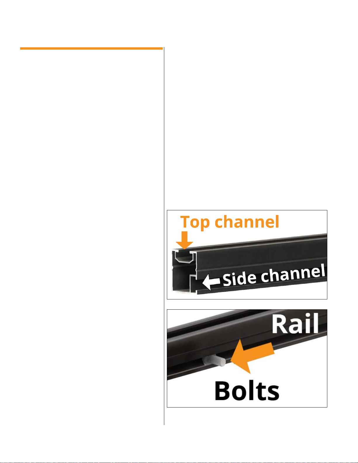
3. Position the rails on the roof, adjacent to the L-
feet and such that the side channel of each rail
is facing the roof peak (Fig. 3 and Fig. 5).
4. For each rail, determine the number of L-feet to
which it will attach, and then slide that number
of bolts into the rail’s side channel (bolt heads fit
into channel; Fig. 4). For bolt specification see
Section 1.33.
Important! For your roof attachment strategy,
remember that a spliced rail is the same as a
solid rail in that a spliced rail does not require
any special allowance in terms of overhang
or attachments.
Document #518101 RevD
Fig. 3
Fig. 4
29 SunPower Proprietary
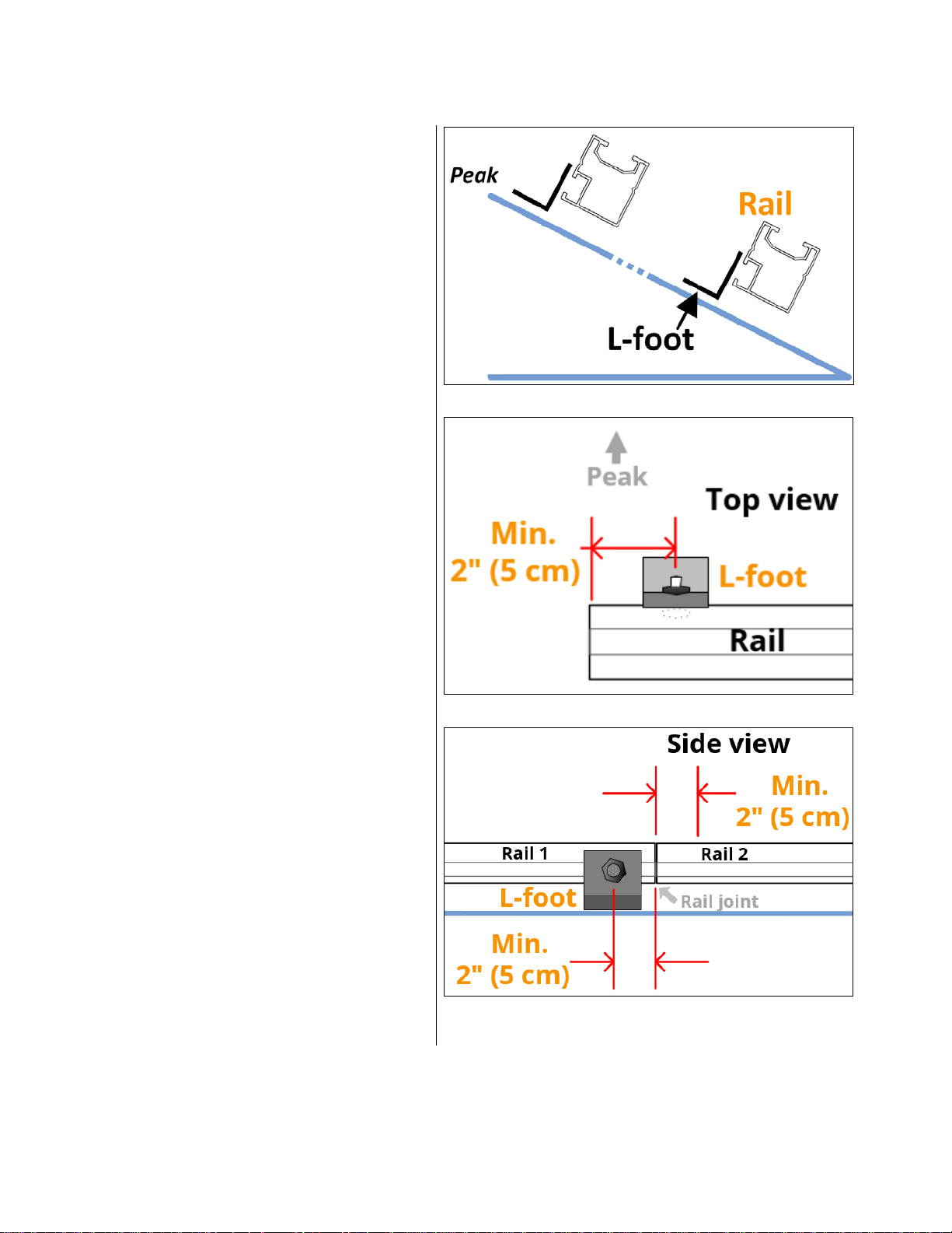
5. Position the rail—with its side channel facing the
peak—adjacent to and “below” (relative to the
peak) the L-feet for the given row (Fig. 5).
Note: L-feet must only “face” the peak (Fig. 5
and Fig. 6).
6. Position the rail bolts a minimum of 2″ (5 cm)
from the end of a rail (Fig. 6); and a minimum of
2″ (5 cm) from any rail joint (Fig. 7).
Fig. 5
Fig. 6
Document #518101 RevD
Fig. 7
30 SunPower Proprietary
 Loading...