

SunPower 503252 Users Manual

MANUAL, INSTALLATION AND CONFIGURATION,
™
DTMAC
ADVANCED TRACKER CONTROLLER
Document Number:
JULY 2013
R K JUPALLI
REV. ECO# DESCRIPTION DATE AUTHOR
0 Preliminary Draft 05/03/13 RK Jupalli
1 Initial Draft Release 05/31/13 RK Jupalli
2 Revised Draft 07/03/13 RK Jupalli
SUNPOWER CORPORATION
77 Rio Robles
San Jose CA 95134
1-800-SUNPOWER
www.sunpowercorp.com

DTMAC™ Advanced Tracker Controller
INSTALLATION AND CONFIGURATION MANUAL
© SunPower Corporation
All Rights Reserved
Document # Rev 02 1 PROPERTY OF SUNPOWER CORPORATION
CONFIDENTIAL INFORMATION

1.1 Overview ..................................................................................................................................................... 5
1.2 Safety Procedures ....................................................................................................................................... 6
1.2.1 Radio Frequency Safety ...................................................................................................................... 6
1.2.2 Electrostatic Discharge .............................................................................................................................. 7
1.2.3 Shock Hazards ..................................................................................................................................... 7
1.2.4 Temperature Hazards .......................................................................................................................... 7
1.2.5 Handling Hazards ................................................................................................................................ 7
2.0 Configuring the DTMAC Tracker Controller .................................................................................................... 8
2.1 Mounting the Controller ............................................................................................................................... 8
2.2 Wiring the Controller ................................................................................................................................... 8
2.3 Connecting the East and West Branch Motor Cables .............................................................................. 14
2.4 Smart Motor Configuration Procedure ...................................................................................................... 14
2.4.1 Overview ............................................................................................................................................ 14
2.4.2 Motor Configuration ........................................................................................................................... 14
2.5 Setting Parameters and Verifying Functionality ........................................................................................ 17
2.5.1 Setting System Parameters ............................................................................................................... 19
2.5.2 Verifying Motor and Controller Wiring ................................................................................................ 27
2.5.3 Verifying Array Flatness ..................................................................................................................... 27
2.5.4 Verifying East and West Limits .......................................................................................................... 28
2.6 Configuring a Computer for DTMAC Programming .................................................................................. 29
2.6.1 Overview ............................................................................................................................................ 29
2.6.2 Installing the DTMACterm Application ............................................................................................... 29
Appendix A: PANID Decimal to Binary Switch Position Conversion Tables ........................................................... 33
Appendix B: Remote Access Procedures................................................................................................................ 38
B.1 Overview of Control Interface and Capabilities ......................................................................................... 38
B.2 User Types ................................................................................................................................................ 38
B.3 Accessing the SunPower DTMAC Controller Monitoring Application ....................................................... 40
B.3.1 Logging In .......................................................................................................................................... 40
B.3.2 Viewing Site Information .................................................................................................................... 46
B.3.2.1 Using the Main or Dashboard Tab Page .................................................................................... 46
B.3.2.2 Using the Sites Tab Page ........................................................................................................... 49
B.3.2.3 Using the Customers Tab Page ................................................................................................. 52
Document # Rev 02 2 PROPERTY OF SUNPOWER CORPORATION
CONFIDENTIAL INFORMATION

B.3.3 Viewing Network Information ............................................................................................................. 55
B.3.3.1 Using the Main or Dashboard Tab Page .................................................................................... 55
B.3.3.2 Using the Networks Tab Page .................................................................................................... 57
B.3.3.3 Using the Customers Tab Page ................................................................................................. 60
B.3.3.4 Using the Sites Tab Page ........................................................................................................... 62
B.3.4 Viewing DTMAC Unit Information ...................................................................................................... 63
B.3.4.1 Using the Main or Dashboard Tab Page .................................................................................... 63
B.3.4.2 Using the Units Tab Page ........................................................................................................... 66
B.3.4.3 Using the Networks Tab Page .................................................................................................... 69
B.3.5 Using the Graph ................................................................................................................................. 70
B.3.6 Viewing System Status ...................................................................................................................... 77
B.3.7 Viewing and Adding Controller Events .............................................................................................. 79
B.3.7.1 Viewing Controller Events .......................................................................................................... 79
B.3.7.2 Adding Controller Events ............................................................................................................ 80
B.3.8 Setting or Modifying Configuration Parameters ................................................................................. 81
B.3.8.1 Using the Main or Dashboard Tab Page .................................................................................... 81
B.3.8.2 Using the Units Tab Page ........................................................................................................... 84
B.3.9 Sending Remote Updates .................................................................................................................. 85
B.3.9.1 Using the Main or Dashboard Tab Page .................................................................................... 85
B.3.9.2 Using the Units Tab Page ........................................................................................................... 86
B.3.10 Stowing the Array and Setting the Nighttime Angle ........................................................................... 87
B.3.11 Viewing Recent Updates .................................................................................................................... 89
B.3.11.1 Using the Main or Dashboard Tab Page .................................................................................... 89
B.3.11.2 Using the Units Tab Page ........................................................................................................... 90
B.3.12 Viewing Messages ............................................................................................................................. 92
B.3.12.1 Using the Main or Dashboard Tab Page .................................................................................... 92
B.3.12.2 Using the Units Tab Page ........................................................................................................... 94
B.3.13 Viewing Alerts .................................................................................................................................... 95
B.3.14 Creating, Editing, and Deleting Customer Information ...................................................................... 99
B.3.15 Creating, Editing, and Deleting Site Information .............................................................................. 101
B.3.16 Creating, Editing, and Deleting Network Information ....................................................................... 104
B.3.17 Assigning DTMAC Units .................................................................................................................. 106
Document # Rev 02 3 PROPERTY OF SUNPOWER CORPORATION
CONFIDENTIAL INFORMATION

B.3.18 Editing and Deleting DTMAC Unit Information ................................................................................ 110
Document # Rev 02 4 PROPERTY OF SUNPOWER CORPORATION
CONFIDENTIAL INFORMATION
1.0 Introduction
1.1 Overview
The SunPower® Tracker features an embedded computer that controls the movement of the drive unit, which in
turn rotates the torque tubes and optimally positions the CPV modules. The Distributed SunPower Tracker
Monitoring and Control
between the sun and the modules. The DTMAC intelligently controls multiple trackers (16) to be synchronous at
the same time.
The DTMAC controller has remote control capability that allows for stowing in adverse weather condition,
equipment monitoring, and system optimization. Remote access procedures that enable monitoring and control of
correctly installed and configured DTMAC units are described in Appendix B.
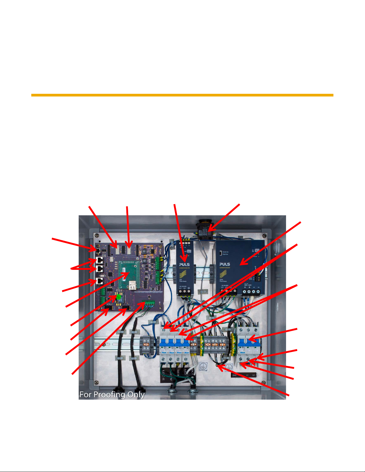
Here is an inside view of the DTMAC controller (Fig. 1):
™
(DTMAC) Advanced Tracker Controller is programmed to optimize the angle of incidence
PROGRAMMING
PORT
STRING
MONITORING
PORT
GPS PORT
NETBURNER®
MODULE
XBee® ROUTER
MODULE
MODE SWITCH
DIRECTION
SWITCH
PAN-ID DIP
SWITCH
NODE-ID DIP
SWITCH
LOGIC POWER
SUPPLY
E-STOP NC/NO/LED
BLOCKS
MOTOR POWER
SUPPLY
MOTOR LOGIC
CIRCUIT
BREAKERS
MOTOR POWER
CIRCUIT
BREAKERS
480VAC CIRCUIT
BREAKER
L3
EARTH
/GND
L2
L1
CAN-BUS PORT
Fig. 1 Internal view of the DTMAC Solar Tracker Controller
Document # Rev 02 5 PROPERTY OF SUNPOWER CORPORATION
CONFIDENTIAL INFORMATION

1.2 Safety Procedures
Important! All personnel must adhere to the following safety procedures when working on the DTMAC controller.
These wiring and configuration instructions are for use by qualified personnel only.
1.2.1 Radio Frequency Safety
The DTMAC controller product is FCC and IC certified.
The design of the DTMAC controller complies with the updated standards for safety levels with respect to
human exposure to Radio Frequency (RF) emissions adopted by the Federal Communications Commission
(FCC) in August 1996.
FCC Notice 15.105:
This equipment has been tested and found to comply with the limits for a Class B digital device, pursuant to part
15 of the FCC Rules. These limits are designed to provide reasonable protection against harmful interference in a
residential installation. This equipment generates uses and can radiate radio frequency energy and, if not installed
and used in accordance with the instructions, may cause harmful interference to radio communications. However,
there is no guarantee that interference will not occur in a particular installation.
FCC Notice 15.21:
Changes or modifications not expressly approved by the party re sponsible for compliance could void the user's
authority to operate the equipment
IC CES-003 - CAN ICES-3 (B)/NMB-3(B):
This devices complies with Industry Canada license-exempt RSS standard (s). Operation is subject to
the following two conditions:
1.This device may not cause harmful interference;
2.This device must accept any interference received, including interference that may cause undesired operation
of the device.
This product meets the applicable Industry Canada technical specifications.
Cet appareil est conforme à Industrie Canada une licence standard RSS exonérés (s). Son fonctionnem ent est
soumis aux deux conditions suivantes:
1. Cet appareil ne doit pas provoquer d'interférences
2. Cet appareil doit accepter toute interférence reçue, y compris les interférences pouvant provoquer un
fonctionnement indésirable de l'appareil.
Ce produit est conforme aux spécifications d'Industrie Canada.
Document # Rev 02 6 PROPERTY OF SUNPOWER CORPORATION
CONFIDENTIAL INFORMATION

1.2.2 Electrostatic Discharge
Warning! Static charge buildup and discharge can damage the DTMAC controller.
To avoid static charge buildup or discharge into the equipment:
Before touching or connecting a laptop to the DTMAC controller, SunPower recommends discharging the
laptop and yourself by simultaneously holding your laptop and grounding yourself to a metal service that is
connected to earth ground.
Use a grounding mat when working on the DTMAC controller.
Use a grounding strap when working on the DTMAC logic board.
1.2.3 Shock Hazards
Warning! Lethal voltages are present in the DTMAC controller box. SunPower recommends not carrying out work
on or near an energized controller. If it’s necessary to work on an electrically active controller, ensure that you use
appropriate Personal Protection Equipment (PPE) at all times.
The DTMAC controller is designed to operate at 380 VAC–480 VAC 3-Phase power. Other voltages are not
compatible.
The DTMAC controller is designed with finger guards to protect the user from electrical shock. However,
SunPower requires that all personnel working on the equipment wear rubber insulating gloves.
1.2.4 Temperature Hazards
Warning! The temperatures inside the DTMAC enclosure can go well above 70 degrees depending on the
ambient temperatures. The surfaces inside the enclosure can be hot and care must be taken to let the enclosure
cool down and the power must be shut-off before performing any kind of maintenance or installation operations.
The DTMAC controller is designed to operate in the temperature range of -25 to +60 degrees C.
1.2.5 Handling Hazards
Warning! The DTMAC product needs to be handled properly by able bodied personnel in order to move the
product or during installation, as the product weighs 30lbs and can pose physical harm when dropped or not
handled right. The product also has a hinged cover which needs to be secured before moving or installing the
product.
The handling and orientation of the DTMAC controller is provided on the field assembly sheets and in this
document.
Document # Rev 02 7 PROPERTY OF SUNPOWER CORPORATION
CONFIDENTIAL INFORMATION

2.0 Configuring the DTMAC Tracker Controller
Important! Do not attempt to change any of the DTMAC controller’s specified parameters. Doing so could
dramatically alter system functionality and its ability to gather energy. Contact the DTMAC Monitoring team if you
have questions about controller parameters.
You must wire the DTMAC controller and set the parameters so that the tracking functionality will execute
properly. Once configured, new controllers are administered in the SunPower DTMAC Advanced Tracker
Controller monitoring application to complete the commissioning procedure (refer to Appendix B).
2.1 Mounting the Controller
The DTMAC needs to be mounted to the pier using the two clamps (Fig. 2) which come with the DTMAC
packaging. Mount the DTMAC at the specified height from ground level and at the specified location on the pier,
this information should be obtained from the project drawings. The DTMAC needs to be mounted vertical (Fig. 3)
and it should be facing the geographical direction as specified in the project drawings.
2.2 Wiring the Controller
Before performing the steps in this section, refer to the project drawings to identify the following:
the controller designated as the “Coordinator” DTMAC for the network
the controller to be installed with a GPS unit
the mounting orientation of the DTMAC box and identifying the East, West branch motor wires
the controller to be installed with a String Monitor connection.
These units have unique hole-drilling and wiring requirements.
Document # Rev 02 8 PROPERTY OF SUNPOWER CORPORATION
CONFIDENTIAL INFORMATION
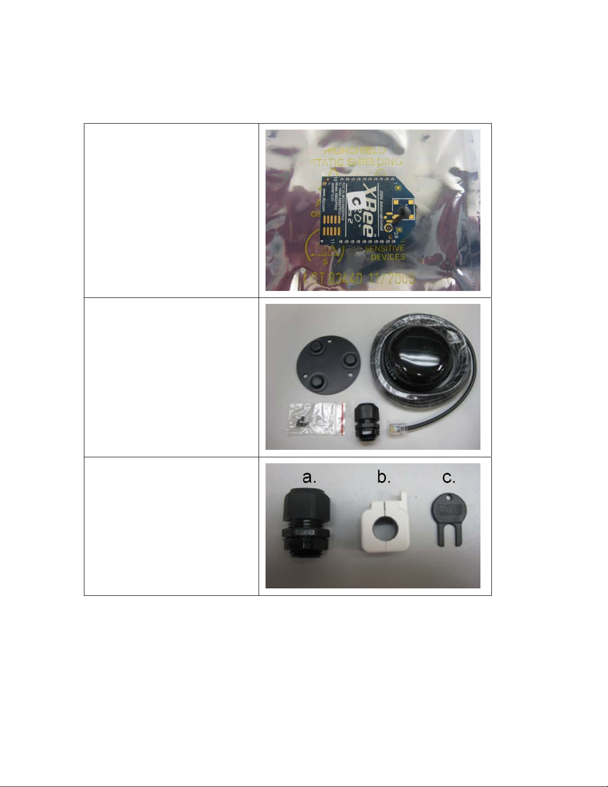
Shipped separately, the DTMAC/TMAC Coordinator Upgrade Kit (SunPower part # 111437) contains components
required for Coordinator conversion of the specified DTMAC unit and to facilitate GPS installation into another
DTMAC:
®
XBee
Coordinator radio chip
(enclosed in antistatic bag)
GPS unit (with cable and
modular jack)
Cable gland for the GPS cable
GPS Magnetic Mount Kit (with
three attachment screws for the
main unit)
a. Cable gland for the Ethernet
cable
b. Snap-on Ferrite
c. Ferrite Safety Key (used to open
the closed ferrite)
Document # Rev 02 9 PROPERTY OF SUNPOWER CORPORATION
CONFIDENTIAL INFORMATION

Important! To minimize the risk of damage to
internal wiring and other components in the
controller box, drill all necessary holes before
attaching wire leads. To reduce fiber dust during
drilling, SunPower recommends that you use a
hole saw.
The DTMAC controller comes preassembled with
the East and West motor wiring branches already
attached.
To connect the wiring to the DTMAC controller:
1. Drill a hole of appropriate size for the input
480VAC power entry cable or conduit (as
specified in the project drawings)
approximately 4″ (10 cm) to the right of the
west branch motor cable entry (Fig. 4)
2. If the controller you are installing is not the
designated Coordinator DTMAC or GPS unit,
proceed to Step 6.
3. If the controller is the Coordinator DTMAC or
the designated GPS unit, drill another hole to
the left of the east branch motor CAN cable
entry (Fig. 5) according to the following
requirements:
If the controller is designated as the GPS
unit:
Drill a hole 7/8″ (22 mm) in diameter for the
GPS cord grip (Fig. 5) contained in the
DTMAC Coordinator Upgrade Kit.
4”
Fig. 4
2”
Fig. 5
If the controller has a string monitor board
connection drill a hole 7/8″ (22 mm) in
diameter 2” (5 cm) above and 2” (5 cm) to
the right of the east branch motor CAN
cable entry for the string monitor cord grip
(Fig. 6)
If the controller is the Coordinator DTMAC:
2”
2”
a. Refer to the electrical wiring diagram to
determine if an outdoor rated Cat 5
Ethernet cable or a specified conduit
fitting is to be installed for Internet
connectivity.
b. If Cat 5 Ethernet cable is to be used,
drill a hole 7/8″ (22 mm) in diameter
for the cable gland (included in the
kit); if conduit fitting is to be used, drill
a hole of appropriate size for the
conduit that serves as the raceway for
Fig. 6
the Ethernet cable (Fig. 5).
Document # Rev 02 10 PROPERTY OF SUNPOWER CORPORATION
CONFIDENTIAL INFORMATION

4. Install the cable or conduit fitting for the power
entry wiring provided at the site.
Bring the 3-phase power entry leads out of the
fitting and then land the L1, L2, and L3 leads,
on the correct terminals of the circuit breaker
(Fig. 7, Marked in a Red box). A black label
under the circuit breaker identifies the terminal
locations. The GND wire must be terminated
with a 10-32 ring terminal and mounted at the
grounding stud location. The grounding stud is
marked with the appropriate label.
Important! Ensure that you land the wires on
the correct terminals.
Note. There should be ferrules installed on the
power wires.
5. Apply 25 in-lbs (2.8 N-m) torque to all of the
recently attached terminals while securely
holding them against the terminal blocks.
Firmly pull on the wires to make sure that all
are securely attached.
Only perform Step 6 on the controller designated
as the GPS unit.
6. To install the GPS cable:
a. Install the cord grip into the hole for the
GPS cable (to the right of the inclinometer
hole).
b. Hand-tighten the locking nut until it is flush
against the inside wall of the enclosure and
then tighten 1/6 turn with a wrench.
GROUNDING
STUD
Fig. 7
GPS CABLE
ETHERNET
CABLE
STRING
MONITOR
CABLE
c. Feed 12″ (30.48 cm) of the GPS cable
through the mounted cord grip.
d. Tighten the cord grip dome until it is flush
Fig. 8
with the fitting and in contact with the gland
base.
e. In the box, route the cable between the
lower right PCB standoff and the enclosure
wall. Route the cable counterclockwise
around the lower standoff and under the
PCB. From underneath the PCB, route the
cable to the topside (Fig. 8). Use the cable
holders which come with the DTMAC
packaging to secure the cable to the back
panel and to route the cable.
f. Insert the RJ45 plug into the modular jack
labeled RJ3-GPS (Fig. 8).
Only perform Steps 7–8 on the controller
designated as the Coordinator DTMAC.
7. To install the Ethernet cable:
Document # Rev 02 11 PROPERTY OF SUNPOWER CORPORATION
CONFIDENTIAL INFORMATION
Fig. 9
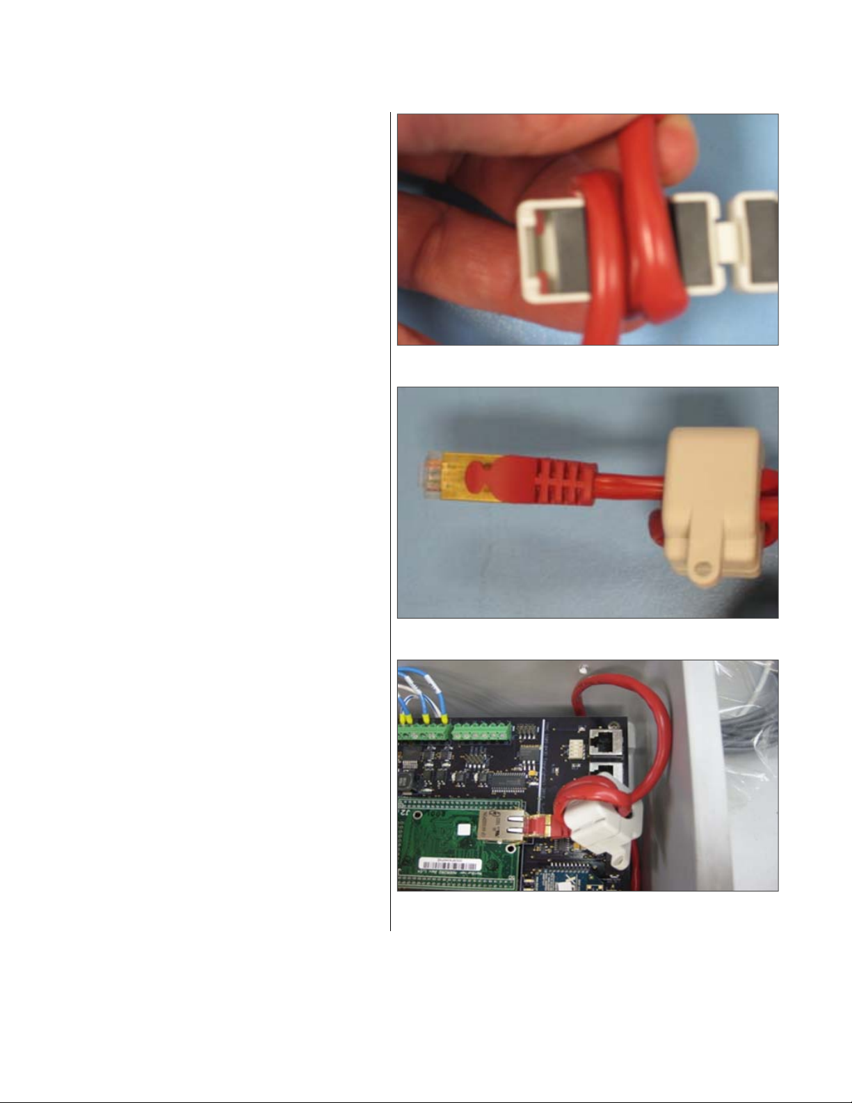
Install the cord grip (if being used) into the hole to
the right of the east branch motor CAN cable entry
hole. Hand-tighten the locking nut until it is flush
against the inside wall of the enclosure and
tighten 1/6 turn with a tool.
If conduit is being used, install the fitting similarly
but tighten 1/2 turn with a tool.
a. Feed the Ethernet cable through the
SunPower provided cable gland (or
conduit—in which case the gland is not
needed) and route the cable between the
front standoff and the enclosure wall (Fig.
8).
b. Coil any excess cable and restrain with the
cable holder or zip tie to maintain isolation
Fig. 10
from the power circuits in the enclosure.
c. Continue to route the cable underneath the
PCB and to the left side of the upper right
standoff (not between the upper standoff
and enclosure wall), and then bring the
cable to the topside of the PCB (Fig. 8).
d. Wrap the cable three times around the
snap-on ferrite (Fig. 9, and Fig. 10) so that
when finished less than one inch of cable
protrudes between the ferrite and the plug
end (Fig. 11).
e. Insert the cable end into the modular jack
on the NetBurner
®
module (Fig. 12).
Fig. 11
Fig. 12
Document # Rev 02 12 PROPERTY OF SUNPOWER CORPORATION
CONFIDENTIAL INFORMATION
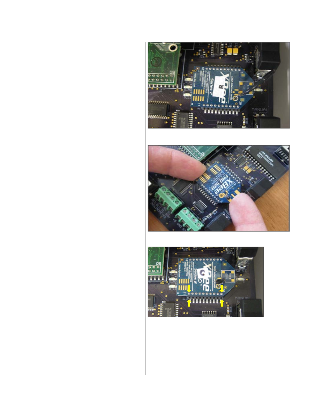
8. To install the Coordinator radio chip:
a. Remove the factory-installed XBee
®
router
module (Fig. 13).
Place an index finger against the router
module’s edge between the DIRECTION
and MODE switches and other index finger
against the opposite edge near the
NetBurner
®
module. With a slight back and
forth rocking action, slowly lift the pins out
of the socket a small amount each time
(Fig. 14).
Important! Ensure that you handle the
router module carefully to avoid damaging
the antenna attached to the PCB.
b. Check that the antenna is perpendicular to
the PCB. Carefully straighten the antenna if
needed.
c. Remove the XBee
®
Coordinator radio chip
from the antistatic bag and position it over
the socket.
d. Make sure that all of the module pins are
aligned with the pin receptacles of the
socket (Fig. 15), and not shifted over by
one pin
e. With a slight back and forth rocking action,
firmly press on both socket rows
simultaneously.
f. Verify that all module pins are directly over
the pin rows of the socket strips (Fig. 15).
The module’s physical shape should
directly coincide with the outline on the
PCB silkscreen overlay. Tug on the wires
gently to ensure that they are properly
seated.
Fig. 13
Fig. 14
9. Check all installed cables before closing the
enclosure
Fig. 15
Document # Rev 02 13 PROPERTY OF SUNPOWER CORPORATION
CONFIDENTIAL INFORMATION

2.3 Connecting the East and West Branch Motor Cables
There is 1 pair each of the East and West branch motor cables already attached to the DTMAC controller. These
cables have connectors already installed at the external end and need to be connected to the East and West
branch extension cables and to the DC smart motor as per the project drawings.
Warning! The power should be turned OFF at the DTMAC controller by switching the respective circuit breakers
(to which these cables are connected inside the DTMAC controller) to the OFF position, before connecting these
cables to either the motor or the East and West branch extensions.
2.4 Smart Motor Configuration Procedure
The DC Smart motor needs to be pre-configured in order to communicate properly with the DTMAC system..
2.4.1 Overview
In order for the TMAC system to function properly each of the 16 motors must be leveled to a reference tracker
surface datum, given a node ID based on the position in the array of 16 trackers, and have the full operational
range verified. Because this does not require communication with the DTMAC it can be done independently at the
tracker using a PC with a software tool (or skilled operator) that compares a temporary reference sensor to the
motor sensor.
2.4.2 Motor Configuration
In order for the PC to command the motor, the CANbus Y-connector on the motor must be unplugged and the
cable from the PC used in its place. If field power is active the motor power cable can remain in place – otherwise
a mobile 24V supply is required to power up the motor during commissioning.
The PC is used to command the motor to drive to a position where the reference sensor is level (0°) and then a
command is issued for the motor to reset the internal sensor to zero. Due to the use of a hysteresis value when
tracking, the motor must be at least 0.15 deg away from a reference point in order for the motor to attempt a
repositioning move. For this reason the motor is first commanded to drive to +1 deg.
When the motor resets the inclinometer, the setting is stored in non-volatile memory in the sensor and will not be
lost if the power is cycled. A safety feature integrated in the motor firmware will prevent the reset from occurring if
the angle of the internal sensor reads more than 2 degrees. If the reset is attempted beyond 2 degrees the motor
will go into an error state and store the value -20005 in the motor error register (0x3001.0). Figure A shows a
schematic of a potential automated system that an operator can start with a few clicks from an interface along
with the sequence of commands to level the motor. Table 1 lists the logic and communication steps required for
an automated or manual process.
Document # Rev 02 14 PROPERTY OF SUNPOWER CORPORATION
CONFIDENTIAL INFORMATION
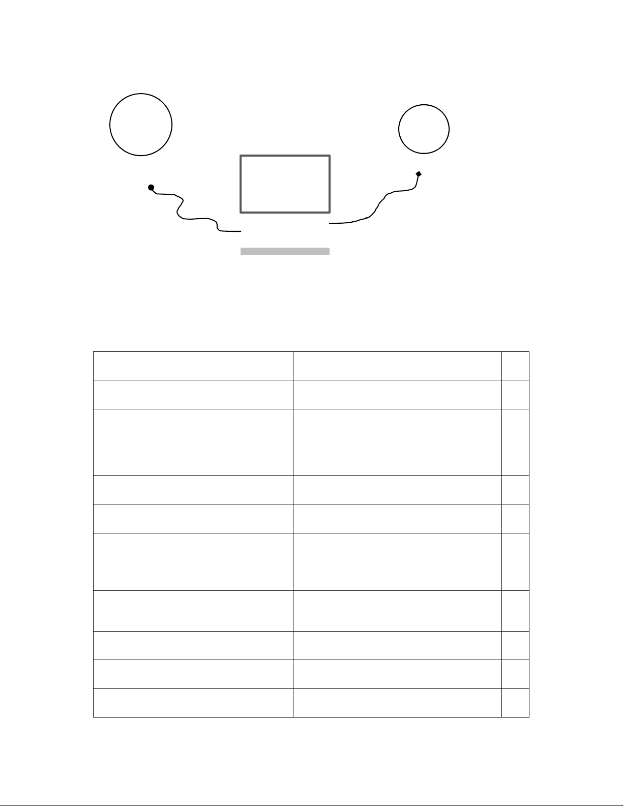
Ref.
Sensor on
Tracker
Motor on
Tracker
PC with interface
to motor & ref
sensor
FIGURE A: Automated motor commissioning system tool.
TABLE 1: Motor commissioning steps.
Description Motor Command or Operation
Operator clicks on “Commission Motor”
Interface button
Step
1
Ask operator if motor is new (ID =127) or
motor is being re-leveled (old ID must be
given for re-leveling)
Tracking command sent to motor
Motor given setpoint (SP) of +1 deg
Monitor motor register MY_STATUS to
know when SP reached.
When SP reached,
Read ref sensor angle value
Read motor sensor angle
Calculate: Motor - Ref = Reset SP
Motor given a setpoint = Reset SP
User interface input
OLDorNEW variable set
If OLD, Store motor ID as MOTOR_ID
SDO-W, NodeID=127, 0x5101.1, 0x05
SDO-W, NodeID=127, 0x5105.1, 100
SDO-R NodeID=127, 0x5102.1
MY_STATUS register will go from 3 up to 6 or 8
then return to 3 when position reached
Reference sensor read by PC
SDO-R, NodeID=127, 0x5103.1
Operator or GUI calc…
SDO-W, NodeID=127, 0x5105.1, RSP
2
3
4
5
6
7
8
9
Document # Rev 02 15 PROPERTY OF SUNPOWER CORPORATION
CONFIDENTIAL INFORMATION

Monitor MY_STATUS to confirm SP
reached (Alternative monitor motor
velocity for return to zero)
Read ref sensor value, check if abs value
<0.05 deg, ELSE return to step 4
If step 11 is true, issue motor inclinometer
reset command
Check motor error status after 3 sec
IF error status = -20005, leveling was
attempted beyond 2° range. Operator
must check system, then click “Clear
error” button to reattempt leveling starting
at step 3.
Reset motor to clear system
IF this was a new motor (See step 2),
Ask operator for block & tracker number
in order to assign proper Node ID (1-16)
SDO-R NodeID=127, 0x5102.1
MY_STATUS register will go from 3 up to 6 or 8
then return to 3 when position reached
Operator or GUI logic check…
SDO-W, NodeID=127, 0x5101.1, 0x02
SDO-R, NodeID=127, 0x3001.0
Power cycle with cable or via the following SDO
write sequence:
User interface input
10
11
12
13
14
15
ELSE: Leveling complete, end routine
Check if block and tracker number valid:
between 1&16, no duplicates. If valid and
different by more than 1 from previous
tracker ask user to verify.
Command motor to reassign node ID
Save Preset value, RSP, with tracker and
block number to record file
Software check
SDO-W NodeId_old, 0x2000.1, 0x6E657277
SDO-W NodeId_old, 0x2000.2, NodeId_new
Response may require 2 sec.
Reset device afterwards:
SDO-W NodeId_old, 0x2009, 1, 0x6E657277
SDO-W NodeId_old, 0x2009, 2, 0x9999
Software operation
16
17
18
Document # Rev 02 16 PROPERTY OF SUNPOWER CORPORATION
CONFIDENTIAL INFORMATION

After the motor is leveled and given a proper node ID, the full range of motion must be verified. If there is any
blockage in the system (such as the hard stop in the slew drive) the motor will likely error out with -4000 (check
error register 0x3001.0). The error must be cleared before the motor will move again. If a hard stop is hit at one of
the maximum extents the motor maximum angle must be changed to prevent repeated errors. Resetting the max
motor angle requires a motor MPU firmware update (see Dunker “Project description file”).
The full operational range test is best performed via the TMAC jog switches as it takes a considerable amount of
time for the motor to complete the 300 degree path while moving at a controlled speed of 4 deg/min (stow to +75
to -75 to stow). Both max positive and negative rotation positions should be verified using the jog switches.
Trackers that hit the hard stop should be fine to rotate to the opposite max extent. Any hard stop hits will be
clearly distinguishable by the orientation the tracker is stuck at when the DTMAC jog switch is cycled back to
stow.
2.5 Setting Parameters and Verifying Functionality
After you install the DTMAC controller, you must assign the controller a node address, level the system, verify
east and west tracking limits, and enter other operational parameters. You must assign a node address, perform
the verifications, and enter the parameters for each DTMAC controller on the site. Once entered, the data is
stored in the non-volatile memory of the DTMAC through an update command.
Important! The GPS device installed in designated DTMAC controllers enables the controller to acquire the
longitude, latitude, and time, and to wirelessly provide the information to the Coordinator DTMAC. The
Coordinator DTMAC then transmits the data to all controllers in the network. Configure the Coordinator and
DTMAC GPS units first so these data can be available as other controllers are configured. A DTMAC controller
without time information will not run in Auto mode.
Note. DTMAC controllers installed with GPS units are usually assigned node address NODEID 1.
You set system parameters by connecting a laptop to the DTMAC controller. The laptop you connect must have
the DTMAC term application installed. The DTMAC term application enables easy configuration of the DTMAC
and quick verification of system functionality.
Important! The laptop you use must be configured for DTMAC programming. Refer to Section 2.5 for the
configuration procedure.
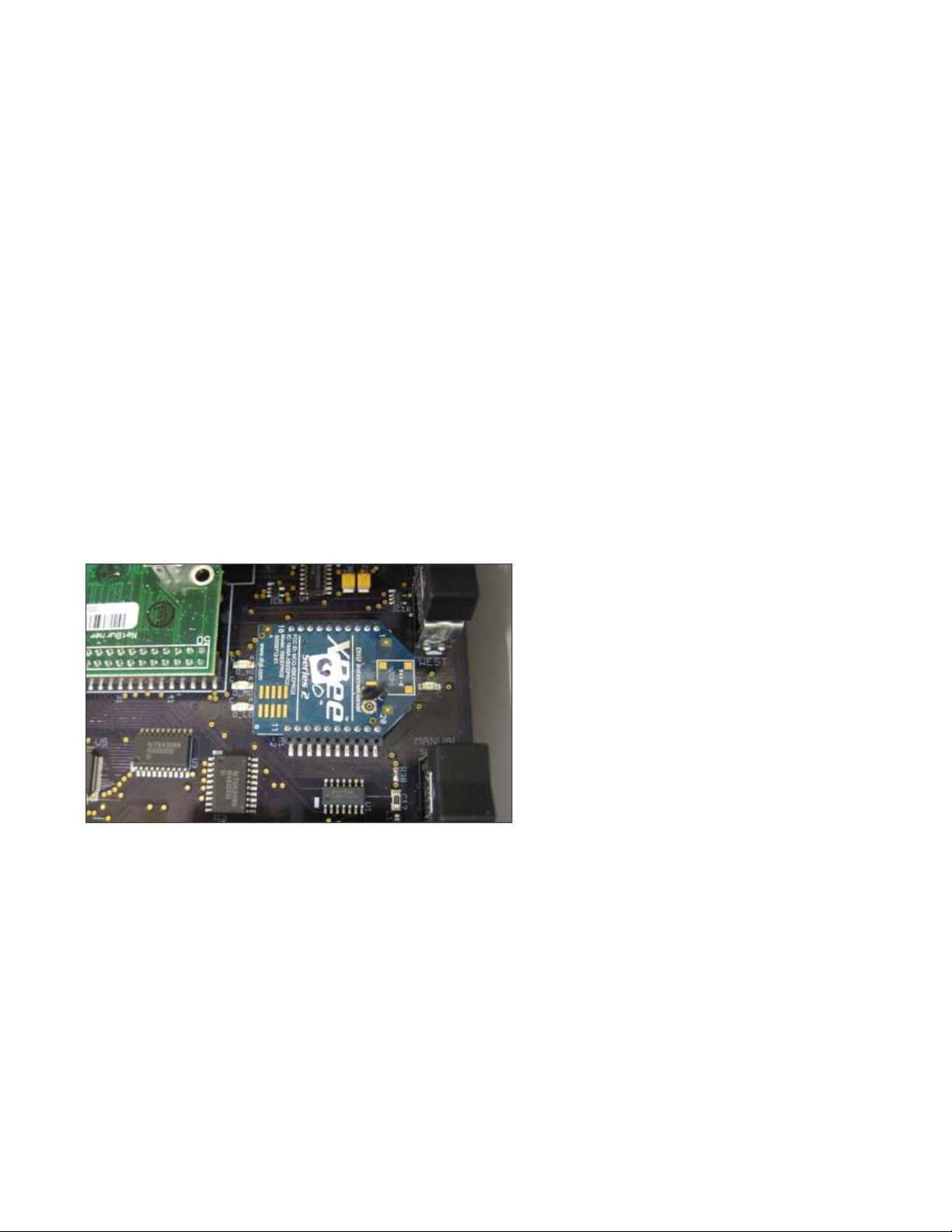
Here is a closer view of the DTMAC controller logic board (Fig. 16):
Fig. 16 DTMAC Tracker controller PCB
Document # Rev 02 17 PROPERTY OF SUNPOWER CORPORATION
CONFIDENTIAL INFORMATION
The state of the DTMAC controller can be manipulated with two 3-position rocker switches: the MODE Switch and
the DIRECTION Switch.
The DTMAC controller has three primary operating modes, activated with the MODE Switch:
AUTO Mode (the middle or neutral position) runs the motor to drive the array that maximizes system power
output (the controller computes the sun’s position and moves the array accordingly)
MANUAL Mode enables the position of the array to be manually adjusted using the DIRECTION Switch:
o EAST (up) runs the motor to tilt the panels to the east
o OFF (the middle or neutral position) turns the tracker motor off
o WEST (down) runs the motor to tilt the panels to the west
There is a time delay enforced if the DIRECTION Switch is too rapidly moved.
STOW Mode runs the motor to the preconfigured ‘flat’ position
Important! Before setting parameters, refer to the project drawings to identify the designated Coordinator
DTMAC unit for the network you are configuring. The Coordinator DTMAC unit, located at the closest inverter
station, is hardwired with Ethernet cable to the site access point (refer to Section 2.2, Step 7). Verify that the unit
has the XBee
®
Coordinator radio chip (marked with a “C“, Fig. 17) instead of the factory-installed XBee® router
module (refer to Section 2.2, Step 8).
Fig. 17
2.5.1 Setting System Parameters
Power on the controller and verify that the LED
marked D_3V near the power supply is lit.
To set the system parameters for each DTMAC
controller:
1. Power down the controller.
2. Refer to the project drawings for the following:
Network Address (PANID) – the address of
this group of DTMAC units
Node Address (NODEID) – the address of
the DTMAC being configured
Important! NODEID 0 is always reserved for
the Coordinator DTMAC unit.
3. Put the MODE Switch in the MANUAL
position.
4. Referring to the Individual Tracker Information
Table, perform the following steps on the
DTMAC address switches:
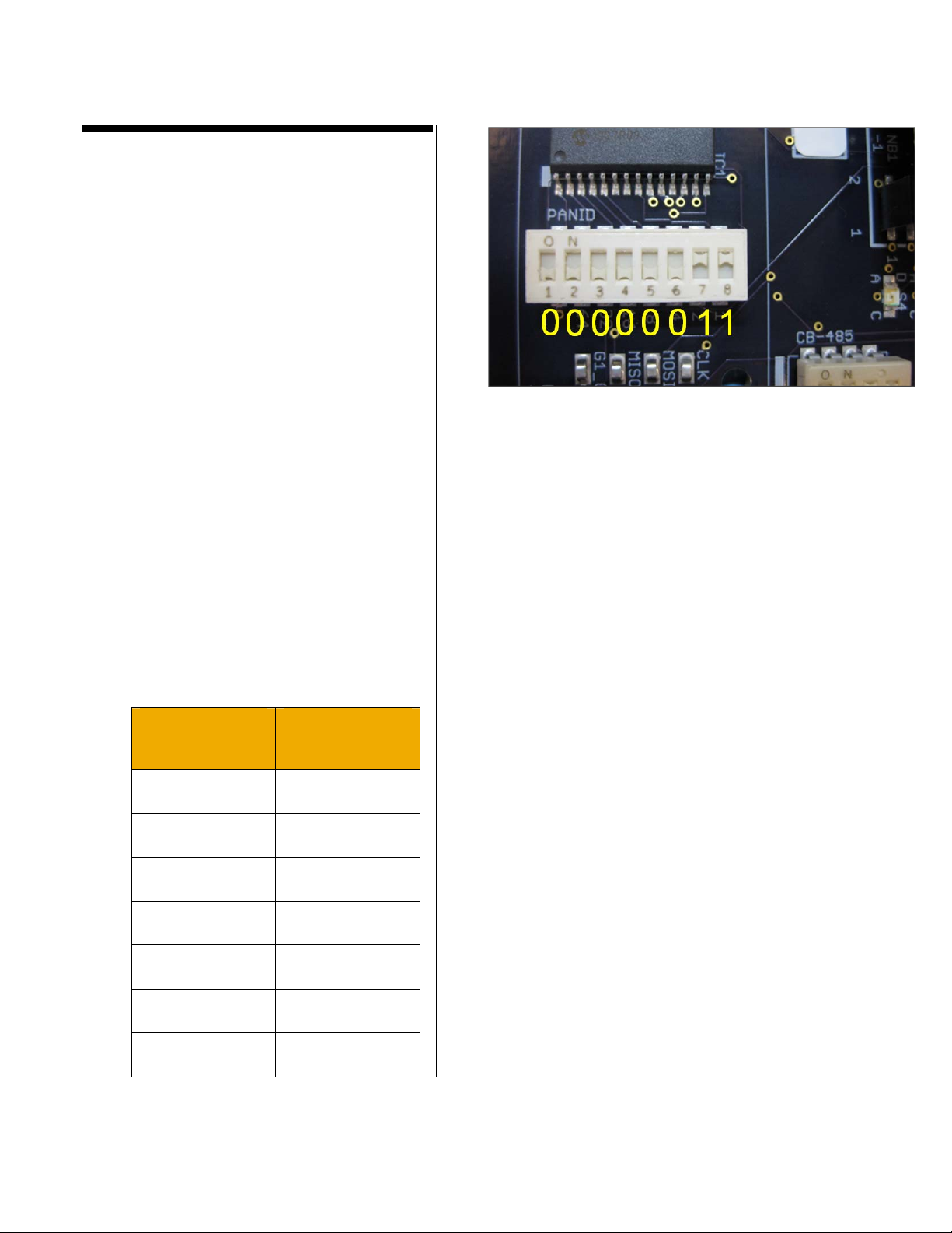
a. Set the PANID Switch:
All of the controllers in a network have the
same PANID. Set all of the units in that
group to that same PANID using the
following table to convert from PANID
decimal to binary switch position.
PANID Number
(Decimal)
Binary Switch
Position
1 00000001
Fig. 18
2 00000010
3 00000011
4 00000100
5 00000101
6 00000110
7 00000111
Document # Rev 02 19 PROPERTY OF SUNPOWER CORPORATION
CONFIDENTIAL INFORMATION
8 00001000
9 00001001
10 00001010
The rightmost digit in the Binary Switch
Position value corresponds to the
rightmost binary switch (labeled 8). The
“up” position (towards ON) of each switch
represents a binary 1, and the “down”
position a binary 0 (Fig. 18).
For example, the PANID Switch is set to
00000011 on a controller that belongs to a
network with PANID 3 (Fig. 18).
Fig. 19
Important! To convert PANID decimals 11
to 255 to binary switch position, refer to
Appendix A.
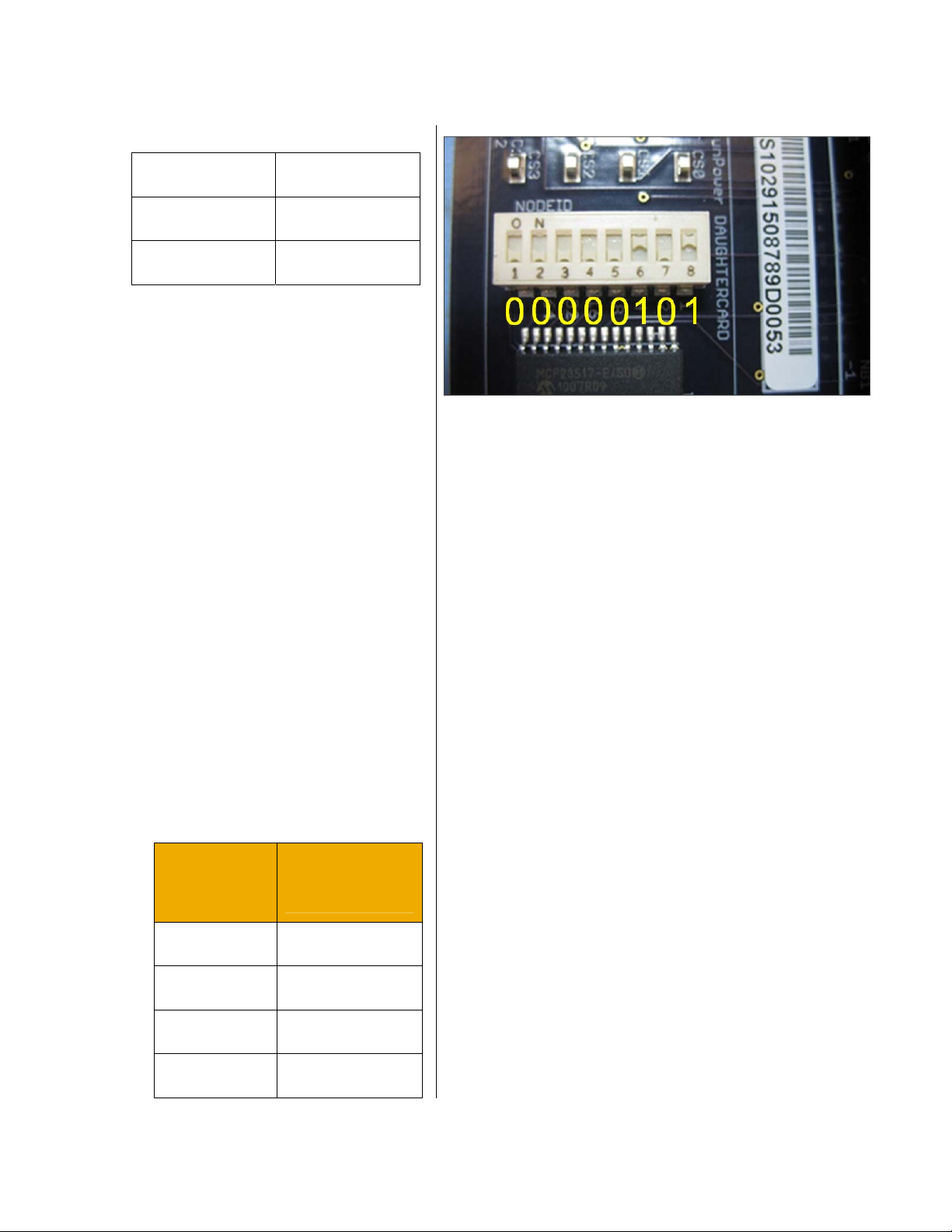
b. Set the NODEID Switch:
On the Coordinator DTMAC unit, set the
NODEID binary switches to 00000000
(all switches down).
For all of the remaining DTMAC units
within this PANID, consult the project
drawings for each controller’s assigned
NODEID. Refer to the following table to
convert from NODEID decimal to binary
switch position.
The individual Binary Switch Position
value correlates with the individual
switch positions as you go from left
(switch 1) to right (switch 8) (Fig. 19).
NODEID
Number
(Decimal)
Binary Switch
Position
1 00000001
2 00000010
3 00000011
4 00000100
Document # Rev 02 20 PROPERTY OF SUNPOWER CORPORATION
CONFIDENTIAL INFORMATION
5 00000101
6 00000110
7 00000111
8 00001000
9 00001001
10 00001010
For example, the NODEID Switch is set
to 00000101 on the controller that is
assigned NODEID 5 (Fig. 19).
5. Use the USB-A to USB-B cable assembly
to connect the laptop to the controller
through the Programming Port.
6. Start the DTMAC term application.
Note: For Windows 7 users, one need to have
UAC disabled on their system in order for the
virtual COM port drivers to be installed by the
DTMAC.
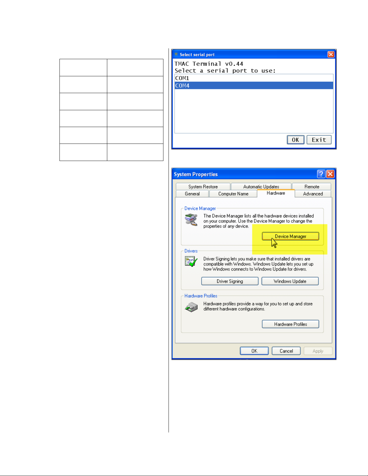
7. The DTMAC term Select serial port
screen opens (Fig. 20):
Select the serial port number being used by
your computer for DTMAC term and then
click OK. Skip Steps 8–11 and proceed to
Step 12.
Fig. 20
To determine the serial port number being
used by your computer for DTMAC term,
perform Steps 8–10.
Perform Steps 8–10 the first time you connect the
computer to a DTMAC controller.
Fig. 21
Note. If in future the USB port is used to connect
the computer to another device, it may be
necessary to perform these steps again the next
time you connect your computer to a DTMAC
controller.
8. Navigate to Start, Settings, Control Panel,
System.
Document # Rev 02 21 PROPERTY OF SUNPOWER CORPORATION
CONFIDENTIAL INFORMATION
9. In the System Properties window, click
the Hardware tab and then the Device
Manager button (Fig. 21).
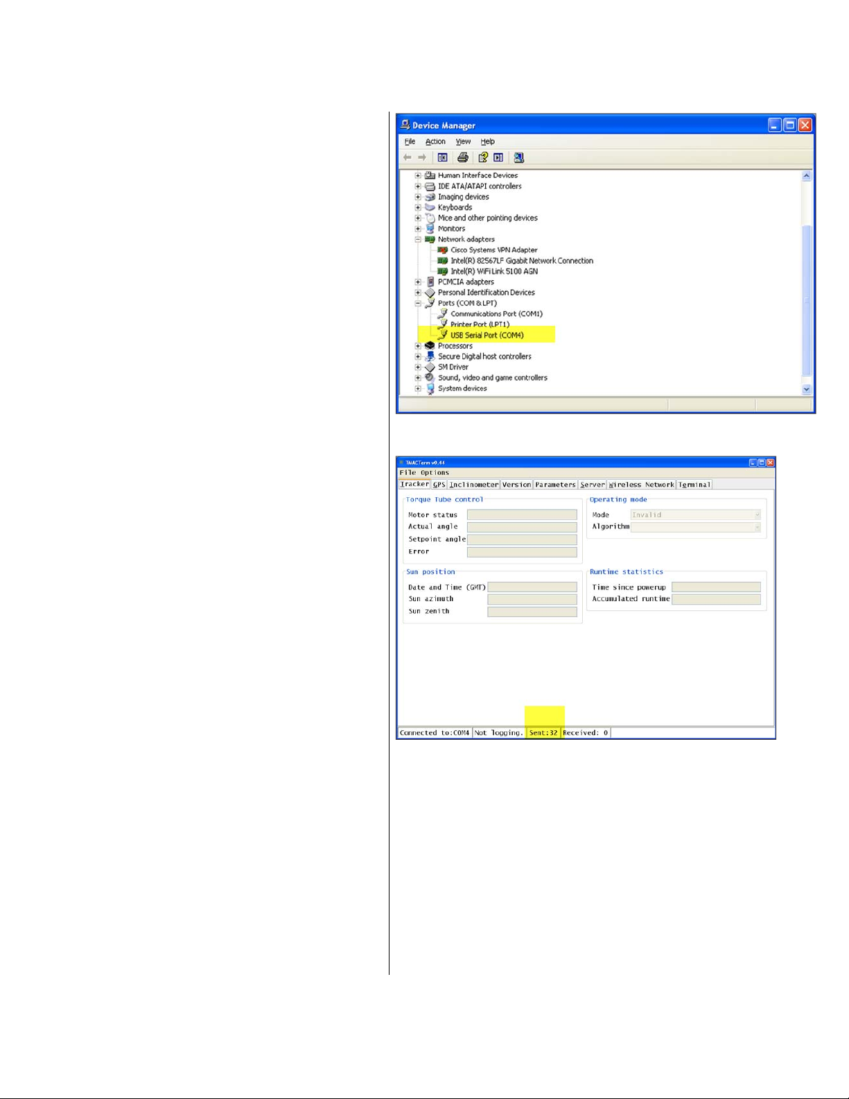
10. In the Device Manager window, scroll
down the list until Ports (COM & LPT) is
found. Expand that entry and look for
USB Serial Port (COM?) (Fig. 22). The ?
(question mark) is the port number being
used by your computer for DTMAC term
(in this case, COM4).
11. Return to the DTMAC term Select serial
port screen and select the COM port
identified. Click OK.
12. The DTMAC term main screen appears
with a dialog box that says ‘Unable to
establish communication with DTMAC’.
Disregard the message and click the OK
button. Note that the only activity present
is the Sent counter at the bottom of the
Fig. 22
window (Fig. 23).
13. Turn on the DTMAC circuit breaker.
Fig. 23
Document # Rev 02 22 PROPERTY OF SUNPOWER CORPORATION
CONFIDENTIAL INFORMATION

In the DTMACterm main screen, a message
‘Can’t parse firmware version’ may appear but
it can be ignored.
After the DTMAC boots up it may not find time
and date information yet. Note that the
Received counter value indicates the number
of messages that the DTMACterm has
received from the DTMAC (Fig. 24).
Fields under Operating mode indicate when
the DTMAC has fully booted in Manual mode
(Jog) and the GPS has been read (Fig. 25).
Other DTMAC units will get their time
information wirelessly from either the GPS unit
or from the Coordinator DTMAC which gets the
time from an Internet clock. The Motor status
error is normal when the DTMAC is in Manual
mode (Fig. 25).
Fig. 24
Fig. 25
Document # Rev 02 23 PROPERTY OF SUNPOWER CORPORATION
CONFIDENTIAL INFORMATION
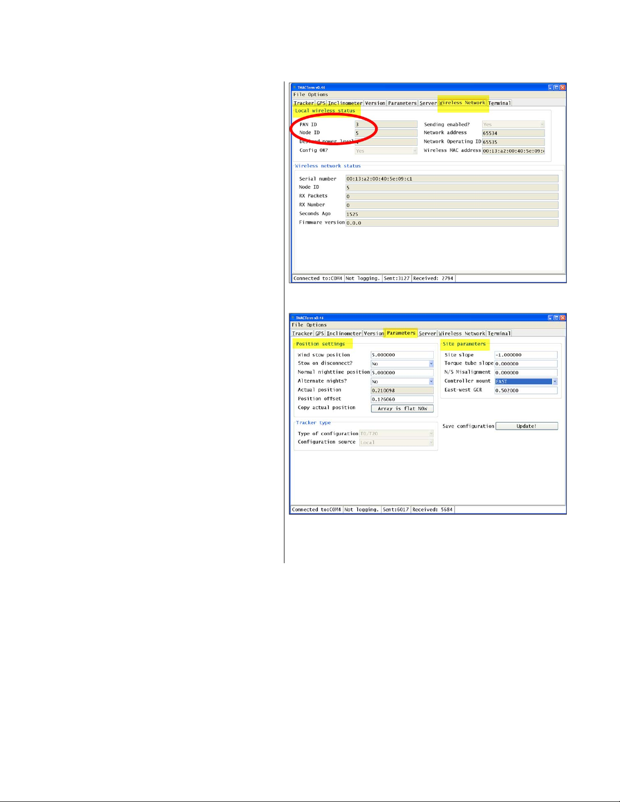
14. Click the Wireless Network tab in the
File Options bar.
15. In the Wireless Network screen, verify
that the PAN ID and Node ID values
under Local wireless status are the
PANID and NODEID decimals,
respectively, specified in the project
drawings (Fig. 26).
16. Click the Parameters tab.
17. In the Parameters screen, enter (or
select) and verify parameter values:
18. Enter (or select) the parameter values
indicated in the project drawings in the
Position settings and Site parameters
fields (Fig. 27).
Fig. 26
Fig. 27
Document # Rev 02 24 PROPERTY OF SUNPOWER CORPORATION
CONFIDENTIAL INFORMATION
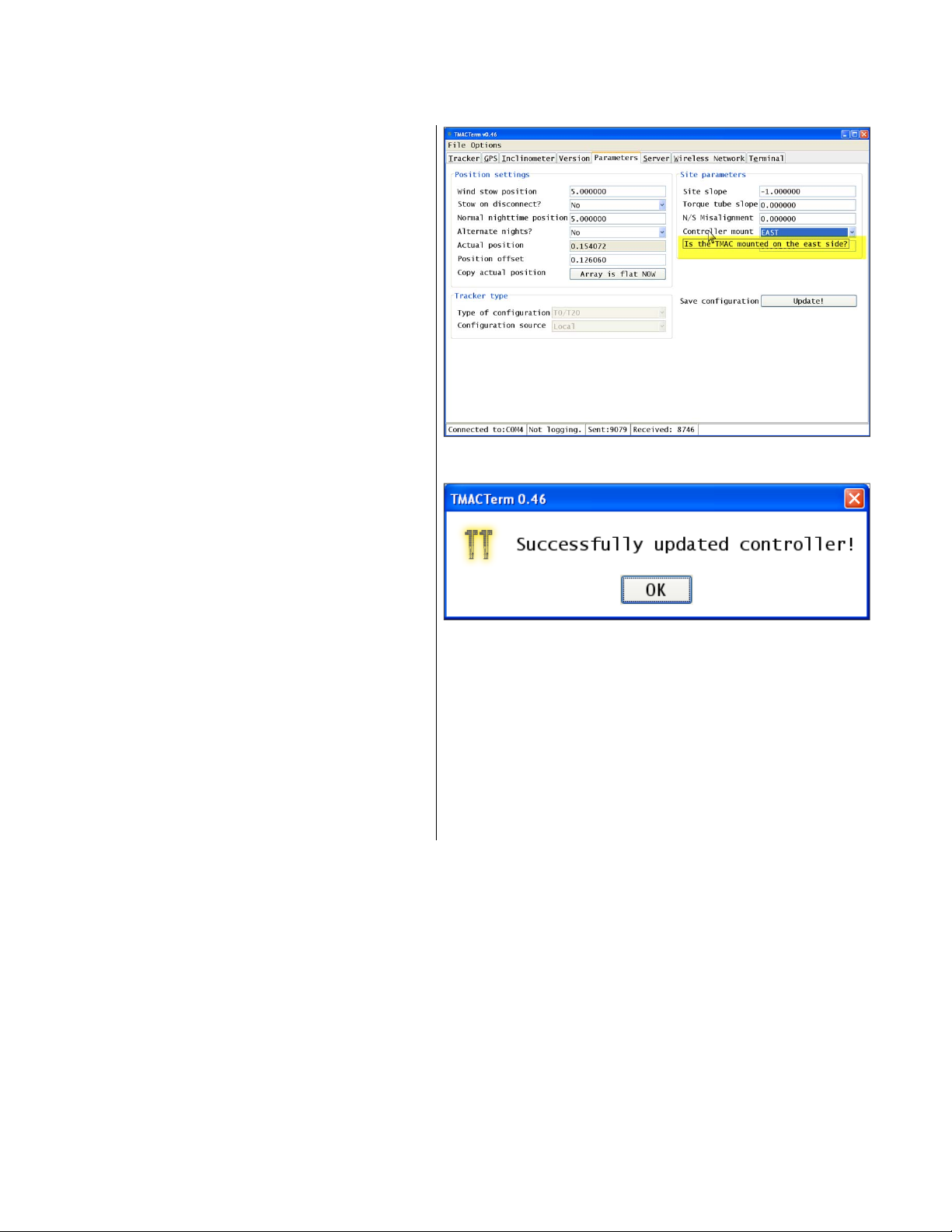
To view the description or details of a field,
position your cursor over the field title (Fig.
28).
19. Verify the Site slope, Torque tube slope,
and East–West GCR values.
Measure the site slope and torque tube
slope using a digital inclinometer.
Measure the E–W GCR using a tape
measure.
Compare the measurements with the
values in the Site slope, Torque tube
slope, and East–West GCR fields. If
the difference between the measured
value and the entered value is less than
1%, proceed to the next step. If the
difference is 1% or greater, contact the
DTMAC Monitoring team.
Fig. 28
20. When all the parameter values have been
entered and verified, click the Update!
button.
21. A confirmation dialog box appears. Click
OK (Fig. 29).
22. To test the entered data:
a. Power down the controller with the DTMAC
circuit breaker.
b. Close DTMAC term and then re-launch the
application after several seconds.
c. Wait 10 seconds before powering the
controller back up.
d. At the DTMAC term main screen click the
Tracker tab and then click the Parameters
tab. Verify that the correct values are stored
in the Parameters screen.
Fig. 29
Document # Rev 02 25 PROPERTY OF SUNPOWER CORPORATION
CONFIDENTIAL INFORMATION

23. Before closing the controller box, verify
that all LEDs (D_S1, D_S2, D_S3, and
D_S4) on the DTMAC PCB are not lit. All
LEDS should be off; otherwise, the
DTMAC will not operate correctly.
When lit, the D_S1 LED indicates that the
controller is in Stow mode; if flashing at 1Hz,
the DTMAC is in Manual.
If the D_S2 LED is flashing, it indicates that the
motor is not under control. Several problems
can cause this condition:
the motor failed to track
there is no valid time in the DTMAC
there is no valid feedback
the temperature in the DTMAC enclosure is
too high, that is, greater than 70° C
The D_S3 and D_S4 LEDs are reserved for
future use. However if both LEDs are lit, either
there is no software loaded on the Netburner
©
module or the DTMAC PCB failed.
Refer to the DTMAC Troubleshooting Guide
for more information.
24. Call or send an email to the DTMAC
Monitoring team to complete the
commissioning procedure and enable
remote control and monitoring for the site.
Provide the site name and location, and
network configuration data indicated in
the project drawings.
Note. You are not required to perform this last
step onsite unless instructed otherwise by the
DTMAC Monitoring team.
Document # Rev 02 26 PROPERTY OF SUNPOWER CORPORATION
CONFIDENTIAL INFORMATION

2.5.2 Verifying Motor and Controller Wiring
1. With the controller box powered down and the door open, turn the MODE Switch to MANUAL. Power up the
controller by turning the circuit breaker on.
2. Turn the DIRECTION Switch to EAST. The modules should begin rotating to the east.
If instead the modules rotate west, verify that the correct mount (EAST or WEST) for the installation is selected
in the DTMAC Parameters screen (refer to Section 2.4.1, Step 19). If WEST is selected in the Controller
mount field and the modules still rotate west, inspect the controller’s power terminal blocks and the motor’s
wiring for reversed polarity. Contact SunPower if the wiring for the controller or motor appears incorrect or not
according to the electrical wiring diagrams.
3. Turn the DIRECTION Switch back to OFF (the middle position, neither EAST nor WEST).
2.5.3 Verifying Array Flatness
A Tracker array is considered “flat” when its modules are at a tilt angle of 0°.
1. Turn the MODE Switch to MANUAL.
2. Turn the DIRECTION Switch to the EAST or WEST positions as necessary to move the modules to a visually
horizontal (flat) position.
3. Use an auxiliary digital inclinometer to measure one of the modules at the center of the first row (or place your
level E−W, across a fairly even, stable module near the drive strut on the first row), and then use the
DIRECTION Switch again to manually move the array, until the auxiliary inclinometer (or level) reads exactly
level (or 0° +/− 0.1°).
4. In the DTMAC term screen, click the Parameters tab. Click the Array is flat NOW button.
5. Click the Update! button and then click OK in the confirmation dialog box.
Document # Rev 01 27 PROPERTY OF SUNPOWER CORPORATION
CONFIDENTIAL INFORMATION

2.5.4 Verifying East and West Limits
Warning! During the following procedure, ensure that you closely observe the movement of the modules so that
you can use the switches to manually stop the motion if the modules do not stop at 75° or if there is risk of
damage.
1. Turn the MODE Switch to MANUAL.
2. Turn the DIRECTION Switch to EAST.
3. Verify that the modules begin rotating to the east.
4. The modules will eventually stop rotating (this will take approximately 22 minutes if the modules were flat when
you started jogging east). Use a digital inclinometer to verify that the module directly above the controller
inclinometer is at 75° ± 2°. If the angle of the module directly above the controller inclinometer is not 75° ± 2°,
you must replace the controller inclinometer. Contact SunPower.
5. Turn the DIRECTION Switch to WEST.
6. Verify that the modules begin rotating to the west.
7. In approximately 45 minutes the modules will stop. Use a digital inclinometer to verify that the module directly
above the inclinometer is at 75° ± 2°. If the angle of the module directly above the controller inclinometer is not
75° ± 2°, you must replace the controller inclinometer. Contact SunPower.
8. Return the DIRECTION Switch to OFF (middle position, neither EAST nor WEST).
9. Turn the MODE Switch to AUTO. The controller will automatically begin driving the modules to the optimal
position for collecting solar energy. If it’s early morning or late afternoon, do not be alarmed if the tracker starts
moving to the nighttime (stow) position. Observe the AUTO mode behavior for ten minutes to ensure that the
controller parameters are stable.
The Tracker is now operational.
Document # Rev 01 28 PROPERTY OF SUNPOWER CORPORATION
CONFIDENTIAL INFORMATION
2.6 Configuring a Computer for DTMAC Programming
Computers used for DTMAC programming must be preconfigured. If the laptop you are using is not
preconfigured, perform the steps in this section.
2.6.1 Overview
Specific software application and hardware enable a computer to communicate with the DTMAC controller:
Software Requirement Hardware Requirements
DTMAC term application
DTMAC term is a SunPower-provided custom application for computer-to-DTMAC communication. A USB/RS232
conversion radio chip is used on the DTMAC PCB to communicate to a computer through the Programming
port.
If you have DTMAC term installed on your computer but the application fails to run, uninstall the application using
the FTClean - Driver Removal Utility and then re-launch the DTMAC term Setup Wizard to install/update/repair
the application. To download and extract the FTClean - Driver Removal Utility zip file, navigate to the FTDI
Utilities web page http://www.ftdichip.com/Support/Utilities.htm. The FTClean - Driver Removal Utility must be run
with Internet connection.
Laptop with USB connection capabilities
USB male A plug to male B mini plug cable
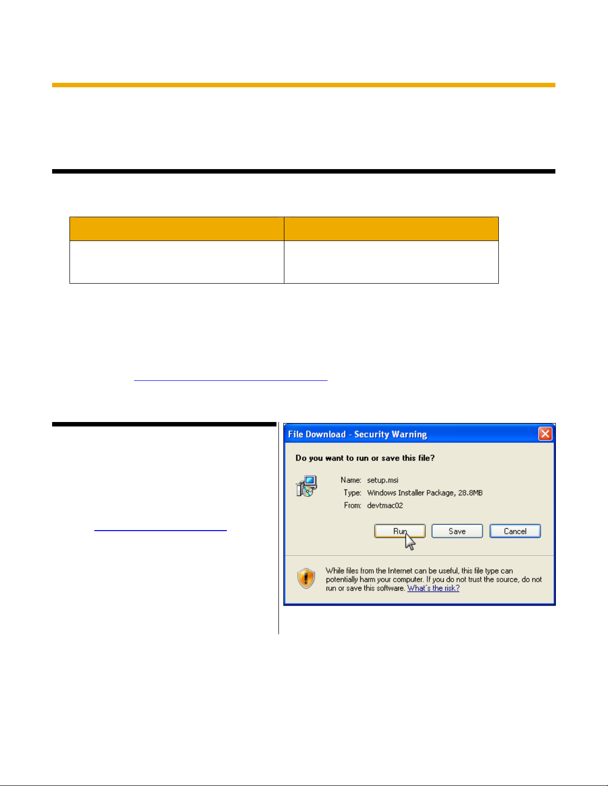
2.6.2 Installing the DTMACterm
Application
The DTMAC term application is available online
through an internal URL. The installer installs both
the DTMAC term software and the required FTDI
driver.
1. Enter http://devDTMAC02/setup.msi in your
web browser.
2. Click Run in the File Download - Security
Warning dialog box (Fig. 30).
Fig. 30
Document # Rev 01 29 PROPERTY OF SUNPOWER CORPORATION
CONFIDENTIAL INFORMATION
 Loading...