

Page 1

WA-1351DE: 12,000BTU DUAL-HOSE SYSTEM
INSTRUCTIONS MANUAL
Thank you for purchasing this Portable Air Conditioner.
Before using the unit, please read this instruction manual carefully and keep it for future reference.
READ AND SAVE THESE INSTRUCTIONS!
Page 2

Contents
e
P r
S a
f
C a u
s
I n
p
O
e
a
M
i n
e s
D
a u
F
a
a
o
t
r
i
p
y P
e
t
t
i
n
o
a
r
i
l
l l
a
t
g
s D
t
a
t
i
e
n
n a
o
t
n
- - - - - - - - - - - - - - - - - - - - - - - - - - -
-
e c a u
r
s
-
- - - - - - - - - - - - - - - - - - - - - - - - - - - - - -
o
t
i
n
-
n
-
- - - - - - - - - - - - - - - - - - - - - - - - - - - - -
a
c
e
n
-
d C o
n
a
i
g
n
o
t
- - - - - - - - - - - - - - - - - - - - - - - - - - - -
m
o s
s
i
n
- - - - - - - - - - - - - - - - - - - - - - - - -
p
l i
s
i
- - - - - - - - - - - - - - - - - - - -
-
a
c e N o
n
- - - - - - - - - - - - - - - - - - - - - -
t
e s
-
- - - - - - - - -
2
3
4
5
9
1 2
3
1
1 4
S o c
a b
i
e R e
l
m
a
r k
-
- - - - - - - - - - - - - - - - - - - - - -
Using the Remote Controller
War ran
t
y
I n f
o
-
- - - - - - - - - - - - - - - -- - - - - - - - -
1
- - - - - - - - - - - - - - - - - -
1 4
5
1
5
2
Page 3
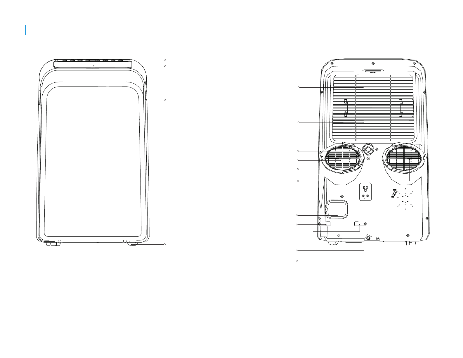
Preparation
control panel
horizontal louver
blade
(swing automatically)
handle
(both sides)
upper air lter
(behind the grille)
upper air intake
drain outlet
air outlet
lower air lter
lower air intake
Caster
power cord outlet
power cord buckle
power plug socket
bottom tray
drain outlet
2
vent control
r e a rf r o n t
Page 4

Safety Precautions
Please read through these instructions before you start the
installation process. Improper installation can cause damage
to the unit, your personal property, and also poses a personal
safety hazard.
• Installation must be performed in accordance to the
installation instructions. Improper installation can
cause water leakage, electrical shock or re.
• Use only the included accessories, parts and specied
tools for installation. Using non-standard parts can
cause water leakage, electrical shock, re, injury or
property damage.
• Make sure the outlet to be used is grounded and has
the appropriate voltage. The power cord is equipped with
a three-prong grounding plug to protect against shock.
Voltage information can be found on the side of the unit,
behind the grille.
• Install the unit on a at and sturdy surface. Failure to do
so could result in damage or excessive noise and vibration.
• The unit must be kept free from obstruction to ensure
proper function and to mitigate safety hazards.
• DO NOT modify the length of the power cord or use an
extension cord. DO NOT share a single outlet with other
electrical appliances. Improper power supply can cause
re or electrical shock.
• DO NOT install the air conditioner in a wet room such
as a bathroom or laundry room. Too much exposure to
water can cause electrical components to short circuit.
• DO NOT install the unit in a location that may be exposed
to combustible gas, as this could cause re.
• The unit has wheels to facilitate moving. Be cautious when
using on thick carpets. Do not roll over objects to avoid
tipping.
• DO NOT operate an unit that has been dropped or damaged.
• Only use the included accessories and specied parts for
installation. Using nonstandard parts can cause water leakage,
electrical shock, re, injury or property damage.
• The unit must be kept free from obstruction to ensure proper
function.
• DO NOT allow children to play with the air conditioner.
• Children must be supervised around the unit at all times.
• If the air conditioner is knocked over during use, turn off the
unit and unplug from power supply immediately. Visually
inspect the unit to ensure there is no damage. If you suspect
the unit has been damaged, contact Sunpentown.
• In a thunderstorm, the power must be cut off to avoid damage
due to lightening.
• The air conditioner is to be used in such a way that is protected
from moisture (condensation, splashed water, etc). Do not
place or store the unit where it can fall or be pulled into water
or any other liquid. Unplug immediately if this occurs.
• Always transport the unit in a vertical position.
• Keep a minimum clearance of 12 inches around the unit for
proper airow (from walls, furniture and curtains).
• When the unit is not in good order, please use common sense
to prevent further damage to surroundings.
• Do not remove any xed covers.
• Never use the plug to start or stop the unit.
• Do not cover or obstruct the inlet or outlet grilles.
• Do not use hazardous chemicals to clean or allow to come in
contact with the unit.
• Do not use the unit in the presence of inammable substances
or vapors such as alcohol, insecticides, petrol, inc.
3
Page 5

Cautions
• This appliance can be used by children aged from 8 years and above and persons with reduced physical, sensory or
mental capabilities or lack of experience and knowledge if they have been given supervision or instruction concerning
use of the appliance in a safe way and understand the hazards involved. Children shall not play the appliance. Cleaning
and user maintenance shall not be made by children without supervision.
• This appliance is not intended for use by persons (including children) with reduced physical ,sensory or mental capabilities
or lack of experience and knowledge, unless they have been given supervision or instruction concerning use of the
appliance by a person responsible for their safety.
• Children should be supervised to ensure that they do not play with the appliance.
• Do not operate unit with a damaged cord or plug. If the supply cord is damaged, it must be replaced by the manufacturer,
its service gent or similarly qualied persons in order to avoid a hazard.
• The appliance shall be installed in accordance with national wiring regulations.
• Do not operate your air conditioner in a wet room such as a bathroom or laundry room.
• Contact Sunpentown regarding issues on repair or maintenance of this unit.
• Contact Sunpentown with questions regarding installation of this unit.
• When there are differences between USERS MANUAL and Remote controller illustration on function description, the
description on USERS MANUAL shall prevail.
• If the air conditioner is knocked over during use, turn off the unit and unplug from the main power supply immediately.
Visually inspect the unit to ensure there is no damage.
• If you suspect the unit has been damaged, contact Sunpentown for assistance.
• Prior to cleaning or other maintenance, please disconnect from power.
• To reduce the risk of re or electric shock, do not use this fan with any solid-state speed control device.
• Do not install the appliance in a location that may be exposed to combustible gas.
• Do not run cord under carpeting. Do not cover cord with throw rugs, runners, or similar coverings. Do not route cord under
furniture or appliances. Arrange cord away from trafc area and where it will not be tripped over.
4
Page 6

Installation
Choosing The Right Location
Note About Fluorinated Gasses
-This air-conditioning unit is a hermetically
sealed unit that contains fluorinated gasses.
For specic information on the type of gas and
the amount, please refer to the relevant label
on the unit itself.
-Service, maintenance and repair of this unit must
be performed by a certied technician.
Your installation location should meet the following requirements:
-Make sure that you install your unit on an even surface to minimize
noise and vibration.
-The unit must be installed near a grounded plug, and the Collection
Tray Drain (found on the back of the unit) must be accessible.
-The unit should be located at least 30cm (12”) from the nearest wall
to ensure proper air conditioning.
-DO NOT cover the Intakes, Outlets or Remote Signal Receptor of the
unit, as this could cause damage to the unit.
NOTE:
All the illustrations in the manual are for explanation
purpose only. Your machine may be slightly different.
The actual shape shall prevail.
The unit can be controlled by the unit control panel alone or
with the remote controller.
5
Page 7
Installation
Tools Needed
-Medium Philips screwdriver; -Tape measure or ruler; -Knife or scissors;
-Saw (optional, to shorten window adaptor for narrow windows)
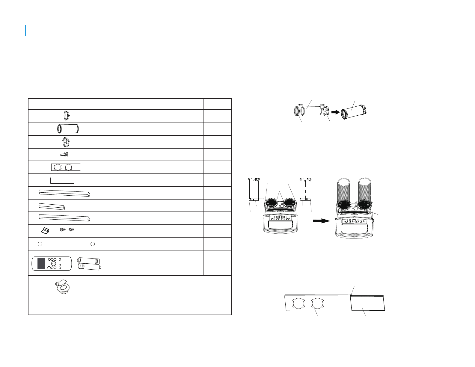
Accessories
Your Window Installation Kit ts windows 67.5-123cm(26.5-48”) and can
be shortened for smaller windows.
Part
Description
Quantity
Window Installation Kit
Step One: Preparing the Exhaust Hose Assemblies
Press window slider adaptor and unit adaptor onto the
exhaust hose. Clips on the adaptors will automatically
clamp onto the exhaust hose.
Exhaust hose
Exhaust hose assembly
Unit Adaptor
Exhaust Hose
Window Slider Adaptor
Bolt
Window Slider A
Window Slider B
Foam Seal A (Adhesive)
Foam Seal B (Adhesive)
Foam Seal C (Non-adhesive)
Security Bracket and 2 Screws
Drain Hose
LED
TIMER
OFF
TIMER
ON
CUT
SHORT
TEMP
SWING
FAN
MODE
SLEEP
ON/OFF
Remote Controller
(2 AAA batteries required, not included)
2 pc
2 pc
2 pc
1 pc
1 pc
1 pc
2 pc
2 pc
1 pc
1 set
1 pc
1 pc
Wall adaptor for through-the-wall
installation. (Not included, option to
purchase.) Please refer to page 8
for installation instructions.
Check all accessories are included in the package and please refer to the installation instructions
for their usage. Note: All illustrations in this manual are for explanation purposes only. Your air
conditioner may be slightly different, the actual shape shall prevail.
Unit adaptor
Window slider adaptor
Step Two: Install the Exhaust Hose Assemblies to the Unit
Align the hooks on the unit adaptor to the hole seat of the
air outlet (located on the back of the unit). Insert adaptor
and slide hose assembly downwards into the groove.
Hole Seat
Groove
Adaptor
Hook
Adaptor
Hook
Make sure each adaptor is
inserted into the groove of
the air outlet.
Step Three: Preparing the Adjustable Window Slider
Depending on the size of your window, adjust the slider kit
accordingly. If the window requires both pieces of the slider
kit, use the bolt to secure the length of the kit.
Bolt
Window slider A
Window slider B
Note: If the window opening is less than the minimum length of the
slider kit, cut Slider A. Cut the solid end, DO NOT cut out the openings.
6
Page 8
Installation
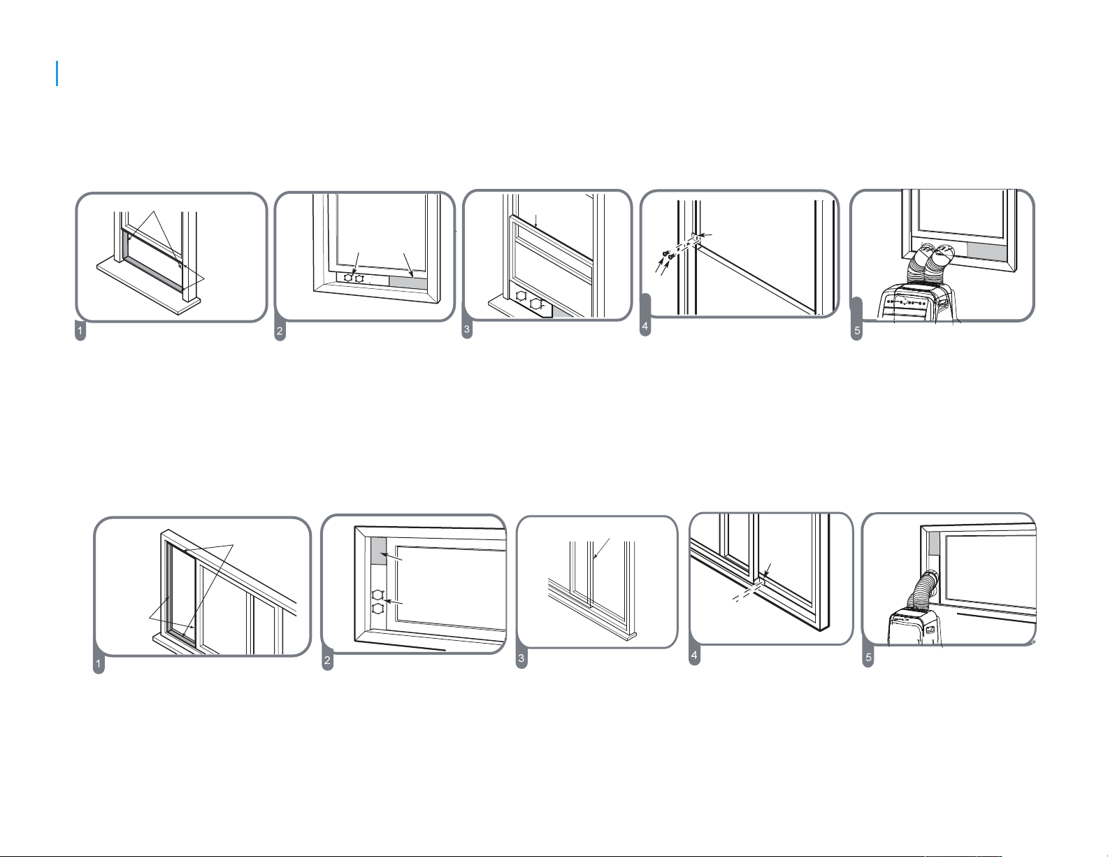
Note: Once the exhaust hose assembly and adjustable slider kit are prepared, choose from one of the following installation methods.
Installation for double-hung window
Foam seal B
(Adhesive type-shorter)
Window slider A
Foam seal A
(Adhesive type)
Cut the adhesive foam
seal A and B strips to the
proper lengths and attach
Insert the slider kit
assembly into window
opening.
them to the window sash
and frame
Installation for sliding window
Foam seal B
(Adhesive type-shorter)
Foam seal A
(Adhesive type)
Window slider B
(if required)
Window slider B
(if required)
Window slider A
Foam seal C
(Non-adhesive type)
Cut the non-adhesive
foam seal C to match
the width of the window.
Insert the seal between
the glass and the
window frame to prevent
air and insect from
getting into the room.
Foam seal C
(Non-adhesive type)
Security Bracket
2 Screws
If desired, install the
security bracket
with 2 screws.
2 Screws
Insert the slider kit
adaptors into the holes
on the slider kit.
Security
Bracket
Cut the adhesive foam
seal A and B strips to the
proper lengths and attach
them to the window sash
and frame
Insert the slider kit
assembly into window
opening.
Cut the non-adhesive
foam seal C to match
the length of the window.
Insert the seal between
the glass and the
window frame to prevent
air and insect from
getting into the room.
7
If desired, install the
security bracket
with 2 screws.
Insert the slider kit
adaptors into the holes
on the slider kit.
Page 9

Installation
Through-the wall connection
Note: It is necessary to purchase the following parts
for through-the-wall installation:
Cover the hole using the adaptor cap when not in use.
Wall Adaptor
(sold separately, please contact
Sunpentown at 1-800-330-0388 or visit
www.sunpentown.com)
Screws & expansion plugs
(can be purchased at any hardware store)
1. Prepare a hole in the wall and install Wall Adaptor
to the opening (from outside). Secure with 4
expansion plugs and screws.
2. Attach exhaust hose to the Wall Adaptor.
Expansion plug
position
Wall Adaptor
Cap
max 47 inches
IMPORTANT:
DO NOT OVER BEND THE EXHAUST HOSE
The exhaust hose can be compressed or extended
moderately according to the installation requirement,
but it is desirable to keep the hose length to a minimum.
CAUTION:
Note: to ensure proper function, DO NOT overextend
or bend the hose. Make sure that there is no obstacle
around the air outlet of the exhaust hose (in the range
of 20 inches) for the exhaust system to work properly.
All illustrations in this manual are for explanation
purposes only.
min 12 inches
8
Page 10

Operation
CONTROL PANEL
Before you begin, thoroughly familiarize yourself with the control panel and remote controller and all its functions, then
follow the symbol for the functions you desire.
The unit can be controlled by the unit’s control panel or with the remote controller.
Swing button
Used to initiate the Auto swing feature.
If auto-swing is in function, press the
button again to stop the louver at
desired angle.
Timer button
Used to initiate the AUTO ON (start time)
and AUTO OFF (stop time) programs.
Used in conjunction with the + and buttons. The corresponding timer indicator
light will illuminate.
Mode button
Selects the appropriate operating mode. Each press
of the button will select mode in the following sequence:
AUTO, COOL, DRY and FAN.
The corresponding mode indicator light will illuminate.
Up (+) and Down (-) buttons
Used to increase or decrease temperature setting
in 1°C/1°F increments.
Adjustable range: 62°F to 86°F (17°C to 30°C)
Also used to set timer between 0 ~ 24 hours.
NOTE: The unit is capable of displaying temperature
in Fahrenheit or Celsius. To convert from one to the
other, press and hold the UP and DOWN keys
simultaneously for 3 seconds.
9
Fan button
Controls the fan speed. Press to select the
fan speed in four steps: LOW, MED, HIGH
and AUTO. The corresponding speed
indicator light will illuminate, except for
AUTO speed. When AUTO is selected, all
fan indicators are dark.
Sleep button
Used to initiate the SLEEP function.
Power button
Power switch, press to turn on/off.
Page 11

Operation
LED display
Displays set temperature, in either °C or °F.
Displays auto-timer settings (if any)
When unit is in DRY or FAN modes, displays current
room temperature.
Displays error codes and protection codes:
E1: Room temperature sensor error
E2: Evaporator temperature sensor error
E3: Condenser temperature sensor error
E4: Display panel communication error
P1: Bottom tray is full. Connect the drain hose to
drain and empty the bottom tray.
Note: When one of the above malfunction occurs,
turn off the unit and check for any obstructions.
Restart the unit, if the error persists, turn off unit
and unplug power cord. Contact Sunpentown
customer service at 800-330-0388.
CAUTION! If unit is stopped or powered off unexpectedly,
there will be a 3-minute delay before unit will start up
again. This is to protect the compressor. Unit will
automatically resume after 3 minutes.
FAN operation
- Press the MODE button until FAN indicator illuminates.
- Press the FAN button to select desired fan speed.
- The temperature cannot be adjusted.
- Exhaust hose connection is not needed.
DRY (dehumidify) operation
- Press the MODE button until the DRY indicator
light illuminates.
- Under this mode, fan speed cannot be selected and
temperature cannot be set. The fan operates at LOW.
- Keep windows and doors closed for the best
dehumidifying effect.
- Do not connect exhaust hose xture to window.
AUTO operation
- When the unit is set in AUTO mode, it will automatically
select cooling or fan mode, depending on set temperature
and ambient room temperature.
- The air conditioner will operate in the appropriate mode
based on the set temperature.
- Under AUTO mode, fan speed cannot be set.
OPERATION INSTRUCTIONS
COOL operation
- Press the MODE button until the COOL indicator
light illuminates.
- Press the + or - button to set desired room temperature.
Temperature range is between 62°F~86°F (17°C~30°C).
- Press the FAN button to choose desired fan speed.
SLEEP function
- If unit is running in COOL mode when SLEEP function is
activated, unit will automatically increase set temperature
by 1°C/2°F after 30 minutes. After another 30 minutes, unit
will again increase temperature by 1°C/2°F.
- Unit maintains the new temperature for 7 hours, then
returns to original set temperature. This ends the Sleep
function and unit operates as originally programmed.
NOTE: This feature is unavailable under FAN or DRY mode.
10
Page 12

Operation
TIMER function
When the unit is operating:
- Press the TIMER button to program auto-stop, the
TIMER OFF indicator will illuminate. Press the + or buttons to set the time for unit to turn off.
- Press the TIMER button again within 5 seconds will
allow you to program auto-start. The TIMER-ON
indicator will illuminate. Press the + or - buttons to
set the time for unit to turn on.
When the unit is off:
- Press the TIMER button to program auto-start, the
TIMER ON indicator will illuminate. Press the + or buttons to set the time for unit to turn on.
- Press the TIMER button again within 5 seconds will
allow you to program auto-stop. The TIMER-OFF
indicator will illuminate. Press the + or - buttons to
set the time for unit to turn off.
- Press or hold the +/- button to change time in 0.5
hour increments, up to 10 hours; then in 1 hour
increments, up to 24 hours. The control panel will
count down the remaining time until program begins.
- The display will automatically revert back to displaying
the previous temperature setting if there is no activity
within a 5 second period.
- After time has been programmed, if unit is manually
turned ON or OFF; or if the timer setting is adjusted to
0.0, all timer programs will be cancelled.
- When unit malfunctions and error codes E1, E2, E3
or E4 is displayed, timer programs will also be cancelled.
Other features
Auto-Restart
If the unit breaks off unexpectedly due to power cut, it will
restart at previous function when power resumes.
Air Flow Adjustment (SWING)
- When the unit powers on, the louver opens fully.
- Press the SWING button to initiate the auto-swing.
The louver will automatically swing up and down.
- For xed angle, press SWING button when louver is
at desired angle.
NOTE: Please do not adjust the louver manually.
VENT CONTROL
The vent control is located at the back of the unit.
The OPEN position removes stale air from the room and
exhausts it outside. Fresh air is drawn in through
normal passages in the home.
When there is no need to circulate the room air, set
vent to CLOSE position.
CLOSE
OPEN
11
Page 13

Operation
Maintenance
Continuous Drainage for DRY mode (optional)
- Remove the upper drain plug
from back of unit.
- Connect drain hose to spout.
- Position the open end directly over drain area.
Note: Make sure
Remove the
upper drain plug
Continuous
drain hose
connection is secure
to prevent leakage.
Make sure there are
no kinks that may stop
the water ow. Do not
raise the hose upwards.
Emptying the Water Tank
When the water in the bottom tray reaches its maximum
capacity, the unit will beep 8 times and display will show
“P1”. At this time, the compressor will immediately stop
(Cool or Dry) but fan will continue to operate.
- Place a collection pan underneath
the drain spout or carefully move
the unit to a drain location.
- Remove the bottom drain plug and
water will begin to drain out.
- Replace the drain plug and restart
unit. P1 indicator should disappear.
Safety Precautions
- Always unplug the unit before cleaning or servicing.
- DO NOT use ammable liquids or chemicals.
- DO NOT wash the unit under running water.
- DO NOT operate the machine if power cord is damaged.
Contact Sunpentown or a qualied electrician.
UNIT HOUSING
Use a lint free cloth soaked with neutral detergent to clean
the housing. Finished by a dry clean cloth.
FILTERS
Clean the lters at least once every two weeks to prevent
inferior fan operation due to dust accumulation.
- Clean lters by washing in warm water (40°C/104°F)
with a neutral detergent. Rinse clean and allow to dry
in a shady area - do not place under direct sunlight.
Uper air lter
(take out)
Filter Removal
This unit has two lters.
- Upper lter: pull and remove
according to arrow direction.
Lower air lter
(take out)
- Lower lter: remove the
screw to remove lter.
12
Page 14

Maintenance
STORAGE
- Drain the unit’s water collection tray according to
instructions in the previous section.
- Run the appliance on FAN mode for 12 hours in
a warm room to dry the interior and prevent mold.
- Turn off the appliance and unplug power source.
- Clean the air lters according to instructions in
the previous section and reinstall.
- remove batteries from the remote control.
Store unit in a cool, dark place. Exposure
to direct sunlight or extreme heat can
shorten the life span of the unit.
NOTE:
- The water collection tray should be drained
immediately after P1 error occurs, and before
storage to prevent mold.
- In household with animals, please clean the
grills periodically (with hand held vacuum or
brush attachment) to prevent blocked airow
due to animal hair.
Design and Compliance Notes
Design Notice
In order to ensure the optimal performance of our products, the design specications
of the unit and remote control are subject to change without prior notice.
Energy Rating Information
The Energy Rating for this unit is based on an installation using an un-extended
exhaust duct without adapters A or B (as shown in the Installation section of this
manual).
Operating Temperature
Mode Temperature Range
Cool 17-35°C (62-95°F)
Dry
Usage Tips
- Use the unit in the recommended room size.
- Locate the unit where furniture cannot obstruct air ow.
- Keep blinds/curtains closed during the sunniest part of
the day.
- Keep the lters clean.
- Keep doors and windows closed to keep cool air in and
warm air out.
- If a very hot day is expected, turn on the unit early to
keep the room cool and keep the heat out.
13-35°C (55-95°F)
13
Page 15

Problem ossible CauPse
P1 Error Code
Unit does not turn
on when pressing
ON/OFF
Unit does not cool
well
butt on
In COOL mode: room
temperature is lower than
the set temperature
The air filter is blocked with
dust or animal hair
Exhaust hose is not
connected or is blocked
The unit is low on
refrigerant
Temperature setting is too
high
Troubleshooting
The Water Collection Tray is full.
Turn off the unit, drain the water
from the Water Collection Tray
and restart the unit.
Reset the temperature
Turn off the unit and clean the
filter according to instructions
Turn off the unit, disconnect the
hose, check for blockage and
reconnect the hose
Call a service technician to inspect
the unit and top off refrigerant
Decrease the set temperature
Sociable Remark
Do not dispose this product as unsorted
municipal waste. Collection of such
waste separately for special treatment is
necessary.
It is prohibited to dispose this appliance
in domestic household waste.
When this product reaches the end of is
useful life, do not dispose with general
household waste. for the correct collection
and treatment of this product, take them to
the collection point for reuse of electrical
and electronic equipment. Contact your
local authority for the appropriate collection
point in your neighborhood.
The unit is noisy
and vibrates too
much
The unit makes a
gurgling sound
The windows and doors in
the room are open
The room area is too large
≤
There are heat sources
inside the room
The ground is not level
The air filter is blocked with
dust or animal hair
This sound is caused by the
flow of refrigerant inside
the unit
Make sure all windows and doors
are closed
Double-check the cooling area
Remove the heat sources if
possible
Place the unit on a flat, level
surface
Turn off the unit and clean the
filter according to instructions
This is normal
14
dispose packaging materials, such as plastic
and carton, in the appropriate waste bins.
Wild disposal of waste in forests and
landscapes endangers your health when
hazardous substances leak into the groundwater and find their way into the food chain.
Page 16

USING THE REMOTE CONTROLLER
emote Contr
R
Battery Required
Signal Receiving Range
Operating temperature -5°C ~ 60°C (23°F ~140°F)
oller Specifica
AAA battery x 2 (not included)
8m
ON /OF F
MOD E
FAN
SLE EP
TE MP
SWI NG
SHO RT
CUT
TIM ER
ON
TIM ER
OFF
LED
tions
NOTE:
Buttons d esign is ba sed on typi cal model a nd might be s lightly d ifferent fr om
the actua l one you pur chased, t he actual s hape shal l prevail .
All the fun ctions de scribed a re accomp lished by t he unit, if t he unit is not
equipped with a certain feature, there will be no co rrespon ding action.
When ther e are wide di ff erences b etween Rem ote contr oller Ill ustrati on and
USERS MAN UAL on functi on descri ption, th e descrip tion on USE RS
MANUAL
shall pre vail.
The devic e could com ply with th e local nat ional reg ulation s. In Canad a, it
should co mply with C AN ICES-3 (B)/NMB -3(B). In U SA, this de vice comp lies
with part 1 5 of the FCC Ru les. Oper ation is su bject to th e followi ng two
conditi ons: (1)Th is device m ay not caus e harmful i nterfe-r ence, and ( 2) this
device mu st accept a ny interf erence re ceived,i ncludin g interfe rence tha t
may cause u ndesire d operati on.
This equi pment has b een teste d and found t o comply wi th the limi ts for a
Class B dig ital devi ce, pursu ant to part 1 5 of the FCC Ru les. These lim its are
designe d to provid e reasona ble prote ction aga inst harm ful int erferen ce in a
residen tial inst allatio n. This equi pment gen erates, u ses and can r adiate
radio fre quency en ergy and, i f not insta lled and us ed in accor dance w it h the
instruc tions, ma y cause har mful inte rferenc e to radio co mmunica tions.
However, t here is no gu arantee t hat inter ference w ill not occ ur in a parti cular
install ation. If t his equip ment does c ause harm ful inter ference t o radio or
televis ion recep tion, whi ch can be det ermined b y turning t he equipm ent off
and on, the u ser is enco uraged to t ry to corre ct the inte rferenc e by one or
more of the f ollowin g measure s:
Reorien t or reloca te the rece iving ant enna.
Increas e the separ ation bet ween the eq uipment a nd receiv er.
Connect t he equipm ent into an o utlet on a ci rcuit diffe rent from t hat to whic h
the recei ver is conn ected.
Consult t he dealer o r an experi enced rad io/TV tec hnician f or help.Ch anges
or modifi cations n ot approv ed by the par ty respon sible for c omplian ce could
void user s authori ty to opera te the equi pment.
The de sign a n d spec ific a tion s are su b ject t o chan g e with out pr i or
notice for product improvement. Consult with the manufacturer for details
15
Page 17

Function Buttons
Before you begin using your new air conditioner, make sure to familiarize yourself with the
remote control.
instructions on operation of the air conditioner, refer to the Instruction Manual.
The following is a brief introduction to the remote control. For detailed
Turns the unit on or off.
ON/OFF
SHORT CUT
Sets and activates your
favorite pre-settings.
Scrolls through modes:
AUTO → COOL
→ HEAT (heating model only)
→
FAN
NOTE: Please do not select
HEAT mode if your model is
cooling only type.
FAN SPEED
Selects fan speeds
in the following order:
AUTO → LOW →
MED → HIGH
→
MODE
DRY
ON/OFF
MODE
FAN
TEMP
SHORT
CUT
TIMER
ON
TIMER
OFF
TEMPp
Increases temperature in
O O
1 C(1 F) increments.
Max. temperature is
O O
30 C(86 F) .
TEMPq
Decreases temperature in
O O
1 C(1 F) increments.
Min. temperature is
O O
17 C(62 F) .
NOTE: Press and hold
and buttons together for
q
p
3 seconds will alternate the
temperature display
between the C & F scale.
O O
TIMER ON
Sets timer to turn unit on
SLEEP
SWING
LED
TIMER OFF
Sets timer to turn unit off
.
Saves energy during
sleeping hours.
SLEEP
LED
Press to turn the LED
,
display on the unit on
SWING
or off.
16
Starts and stops louver
movement.
Page 18

Handling the Remote Controller
NOT SURE WHAT
A
of
Refer to the
manual for a detailed description o
your air conditioner.
Operation Instructions section
FUNCTION DOES?
SPECIAL
Button designs on your unit may differ slightly
from the example shown. When there are wide
differences between Remote controller
illustration and USER'S MANUAL on function
description, the description of USER'S MANUAL
shall prevail.
NOTE
Inserting and Replacing Batteries
The remote controller is powered by two AAA
batteries (not included). The batteries are housed
in the back of the remote, protected by a cover.
Place batteries in the remote control before use.
1. Press down on the cover and slide it outwards
to remove.
2. Insert batteries, paying attention to match the
(+) and (-) ends of the batteries with the symbols
inside the battery compartment.
3. Slide the battery cover back into place.
how to use
n
this
BATTERY
For optimum product performance:
Do not mix old and new batteries, or batteries of
different types.
Remove batteries if the remote will not be used for
more than 2 months
BATTERY
Do not dispose of batteries as unsorted
municipal waste. Refer to local laws for
proper disposal of batteries.
NOTES
DISPOSAL
17
TIPS FOR USING REMOTE CONTROL
The remote control must be used within 8
meters of the unit.
The unit will beep when remote signal is
received.
Curtains, doors, other barriers and direct
sunlightcan interfere with the infrared signal
receiver.
Page 19

emote L een Indicators
R
CD Scr
ransmission Indicator
T
Lights up when remote sends
signal to unit
MODE display
Displays the current
mode, including:
ON/OFF display
Appears when the unit is tur
and disappears when it is tur
ned on,
ned of
f
AUTO
COOL
DRY
HEAT
(Heating models only)
TIMER ON display
Displays when
TIMER
ON is set
TIMER OFF display
Displays when
TIMER
OFF is set
FAN
Battery display
Low battery
detection
SLEEP
display
Displays when
SLEEP function
is activated
FAN SPEED display
Displays selected FAN SPEED:
O
or
This display is blank when
set on
mode.
HIGH,
MED,
LOW
AUTO speed or DRY
18
T
emperatur
e/Timer display
Displays the set temperature by default, or timer setting
when using TIMER ON/OFF functions
Temperatur
T
imer setting range: 0-24 hours
e range: 17-30 C(62
o
F-86
O
F)
This display is blank when operating in FAN mode.
Page 20

w T
o Use T
he Basic Functions
Ho
The operating temperature range for the unit is 17°C-30°C
(62°F-86°F). You can increase or decrease the set temperature
in 1°C(1°F) increments
4
ON/ OFF
2
1
3
1
ON/ OFF
MOD E
FAN
SLE EP
TEM P
SWI NG
SHO RT
CUT
TIM ER
ON
TIM ER
OFF
LED
AUTO OPERATION
In AUTO mode, the unit will automatically select the COOL,
FAN, or DRY mode based on the set temperature.
1. Press the MODE button to select Auto mode.
2. Set your desired temperature using the
Temp or Temp button.
3. Press the ON/OFF button to start the unit.
3
MOD E
TEM P
FAN
SLE EP
SWI NG
COOL OPERATION
1. Press the MODE button to select COOL mode.
2. Set your desired temperature using
the Temp or Temp button.
3. Press the FAN button to select the fan speed:
AUTO, LOW, MED,or HIGH.
4. Press the ON/OFF button to start the unit.
SHO RT
CUT
TIM ER
ON
TIM ER
OFF
LED
2
NOTE: FAN SPEED can t be set in Auto mode.
19
Page 21

Ho
w T
o Use T
3
1
he Basic Functions
2
ON/ OFF
MOD E
FAN
SLE EP
TEM P
SWI NG
SHO RT
CUT
TIM ER
ON
TIM ER
OFF
LED
3
1
2
ON/ OFF
MOD E
FAN
SLE EP
SWI NG
TEM P
SHO RT
CUT
TIM ER
ON
TIM ER
OFF
LED
DRY OPERATION
1. Press the MODE button to select DRY
mode.
2. Set your desired temperature using the
Temp or Temp button.
3. Press the ON/OFFbutton to start the unit.
NOTE: FAN SPEED can not be changed in
DRY mode.
FAN OPERATION
1. Press the MODE button to select FANmode.
2. Press FAN button to select the fan speed:
AUTO, LOW, MED or HIGH.
3. Press the ON/OFF button to start the unit.
NOTE: Temperature cannot be set in FAN
mode. As a result, LCD screen will not
display temperature.
20
Page 22

w T
ON/OFF
MODE
F
AN
SHORT
CUT
TIMER ON
TIMER OF
F
TEMP
S
L
EEP
o Use T
he Basic Functions
Ho
SETTING THE TIMER FUNCTION
Your air conditioning unit has two timer-related functions:
TIMER ON: Set the amount of time after which the unit will automatically turn on.
TIMER OFF: Set the amount of time after which the unit will automatically turn off.
TIMER ON function: Sets amount of time for unit to turn on, such as when you will return home.
Press the TIMER ON button. By default, the last set time and "h" (hour) will appear on display.
Press the TIMER ON button again and repeatedly to set desired time.
When desired time is reached, release button and wait 2 seconds for TIMER ON to activate. Display will return to displaying temperature.
EXAMPLE: if you wish to set TIMER ON for 2.5 hours, press button once to initiate and 5 more times for 2.5 hours. "2.5h" will display on the
screen and unit will turn on after 2.5 hours.
1
TIMER ON TIMER ON
2
x5
3
sec
1
ON/OFF
MODE
SHORT
CUT
F
AN
TEMP
TIMER ON
S
E
L
EP
TIMER OF
F
4
sec
2
Example
hours.
Setting unit to tur
:
n on after 2.5
TIMER OFF function: Sets amount of time for unit to turn off, such as when you pan to leave.
Press the TIMER OFF button. By default, the last set time and "h" will appear on display.
Press the TIMER OFF button again and repeatedly to set desired time.
When the desired time is reached, release button and wait 2 seconds for TIMER OFF to activate.
Display will return to displaying temperature.
EXAMPLE: if you wish to turn unit off after 5 hours.
Press TIMER OFF button once to initiate and press 10more times to set 5.0 hours. "5.0h" will display on thescreen and unit will turn off after 5
hours.
1 2
x10
TIMER OFF TIMER OFF
3
sec
1
4
sec
2
Example
hours.
Setting unit to tur
:
n off after 5
NOTE: When setting TIMER ON or TIMER OFF
functions, each press of button increases the set time
by 30-minutes, up to 10 hours. Then by 1-hour
21
increments, up to 24 hours. Timer will revert to zero
after 24 hours. Either timer function can be turned off by
setting time to "0.0h".
Page 23

Setting combined timers: TIMER ON and TIMER OFF at the same
Keep in mind that the time periods you set for both functions refer to hours after the current time. For example, say that the
current time is 1:00 PM, and you want the unit to turn on automatically at 7:00 PM (which is 6 hours from current time);
operate for 2
Do the following:
hours, then automatically turn off at 9:00 PM (which is 8 hours from current time).
1
TIMER ON
5
TIMER OFF TIMER OFF
2
TIMER ON
6
X12
X16
3
7
4
MODE
ON/OFF
sec
3
SHORT
CUT
TEMP
TIMER ON
8
sec
3
22
ON/OFF
MODE
SHORT
CUT
TEMP
TIMER ON
Page 24

Example:
(see the figure below).
Your remote display
Setting the unit to turn on after 6 hours, operate for 2 hours, then turn off
er o
T im
n
Tim
e r o
ff
imer is set To turn ON
T
6 hours from current time
imer is set to turn OFF
T
8 hours from current time
imer starts
T
Current
time 1PM
2PM
3PM
6 hours later
8 hours later
4PM
5PM 6PM
23
Unit turns
ON
7PM
8PM 9PM
Unit turns
OFF
Page 25

Ho
w T
o Use T
he Advanced Functions
SLEEP
The SLEEP
Function
function is used to conserve energy
,
while you sleep. When activated, unit will
increase set temperature by 1
minutes; and by another 1°C/1°F after additional
30 minutes. New temperature will be maintained
°F after 30
C/1
°
for 7 hours then unit returns to originally set
temperature. This ends the SLEEP function.
The SLEEP function is not available
AN or DRY mode.
in F
SWING Function
Used to stop or start louver movement and set
the desired air flow direction.
One quick press adjusts the angle by 6
. Keep
°
pressing to adjust to desired angle.
Press and hold for 2 seconds to
activate/deactivate auto-swing function.
ON/ OFF
MOD E
FAN
SLE EP
SWI NG
TEM P
SHO RT
CUT
TIM ER
ON
TIM ER
OFF
LED
SHORTCUT function
Used to restore the current settings or resume
previous settings.
On the first time connecting to the power
push the SHOR
operate on
speed is
AUT
Auto.
TCUT
O mode, 26
button, the unit will
O O
C(79 F), and fan
, if
Push this button when remote controller is on,
the system will automatically revert back to
the previous settings including operating mode,
setting temperature, fan speed level and sleep
feature (if activated).
If pushing more than 2 seconds, the system
will automatically restore the current operation
settings including operating mode, setting
temperature, fan speed level and sleep
feature(if activated ).
24
Page 26

Your Guarantee
If this product is found to be faulty as a result of faulty materials or workmanship within one year from date of purchase,
it will be repaired free of charge.
This guarantee is subject to the following terms:
· Sunpentown must be notied of the fault.
· Proof of purchase must be presented to Sunpentown's nominated representative.
· The warranty will be void if the product is modied, misused or repaired by an unauthorized person.
· The warranty after repair will not be extended beyond the original one-year period.
· All replacement parts will be new or reconditioned.
· Parts, which are replaced, become the property of Sunpentown.
· The warranty applies for the use of the product in the USA only.
What is NOT COVERED:
· Warranty does not include freight charges.
· Damage due to installation error, product abuse and/or misuse.
· Incidental or consequential damage caused by possible defects with this product.
· Labor cost incurred for the installation and/or removal of a possible defective unit.
· Damage to product caused by improper power supply voltage, accident, re, oods or acts of nature.
· Failure of product resulting from unauthorized modications to the product.
· Improper installation or failure to perform the necessary maintenance.
· Normal wear and tear on parts or replacement of parts designed to be replaced.
· Damage to personal property from use of product.
· Replacement or repair of household fuses, circuit breakers, wiring or plumbing.
This GUARANTEE is in addition to your Statutory Rights
SUNPENTOWN INTERNATIONAL INC.
14625 Clark Ave. City of Industry, CA 91745
Tel: 800-330-0388
service@sunpentown.com
www.sunpentown.com
25
 Loading...