

Page 1
OWNER’S MANUAL
16” Stand Fan
Model: SF-16T07
Version 1.0 2015
READ AND SAVE THESE INSTRUCTIONS
Attention: Pictures in the IM are for reference only.
Page 2
CAUTION
Read Rules for Safe Operation and Instructions Carefully.
WARNING
1. This appliance has a polarized plug (one blade is wider than the other). To
reduce the risk of electric shock, this plug is intended to t in a polarized outlet
only one way. If plug does not t fully in the outlet, reverse the plug. If it still
does not t, contact a qualied electrician. Do not attempt to defeat this safely
feature.
2. To reduce the risk of re or electric shock, do not use this fan with any solid state
speed control device.
3. Do not leave the fan running unattend.
RULES FOR SAFE OPERATION
1. Never insert ngers, pencils, or any other object through the grille when fan is
running.
2. Disconnect fan when moving from one location to another.
3. Disconnect fan when removing grilles for cleaning.
4. Be sure fan is on a stable surface when operating to avoid overturning.
5. DO NOT use fan in window. Rain may create electrical hazard
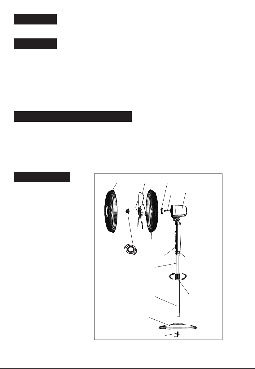
PART FIGURE
Rear Grill
Touch key
Plastic nut
Motor
shaft
Motor Housing
Thumb Screw
Fasten
Height
adjustment ring
Front Grill
Tighten
Spinner
Note: All the pictures in this manual are for explanation purpose only. Any discrepancy between
the real object and the illustration in the drawing shall be subject to the real subject.
Fan Blade
Loosen
Internal Pole
Extension Pole
Chassis
L-shape Bolt
2
Page 3
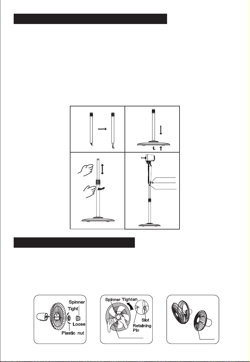
ASSEMBLY OF CHASSIS & COLUMN UNIT
1. Unscrew the L-shape Bolt from bottom of the Extension Pole. (Fig.1)
2. Insert extension pole into the chassis, replace and tighten the L-shape Bolt. (Fig.2)
3. Loosen the height adjustment ring located on the extension and adjust the internal
pole to desired height. (Note: If you don’t see the internal pole, it is inside the
extension pole, simply pull it out.) (Fig.3)
4. Attach the head unit to the internal pole: loosen the thumb screw on the bottom
of the head unit. Place the head unit on the internal pole and tighten the thumb
screw in alignment with the groove on the internal pole. (Fig.4)
CAUTION: Height adjustment ring must be fully fastened before the assembly of the
motor section to the internal pole.
Fig. 1 Fig. 2
Fig. 3 Fig. 4
Loosen
Thumb screw
Ann ular gr oove
GRILL & FAN BLADE ASSEMBLY
1. Unscrew the spinner clockwise (this part may be packed separately in bag)
and unscrew plastic nut counterclockwise to remove. Fix the rear grill onto the
motor shaft, replace plastic nut and turn clockwise to tighten. (Fig. 5)
2. Insert the blade onto the shaft - make sure the rotor shaft pin is fitted into the
groove on the blade. Turn the spinner counterclockwise to tighten blade. (Fig. 6)
3. Fix the front grill to the rear grill and secure with the grill clip. (Fig. 7)
Fig.5
Blade Set
Fig.6 Fig.7
3
Clip
Page 4
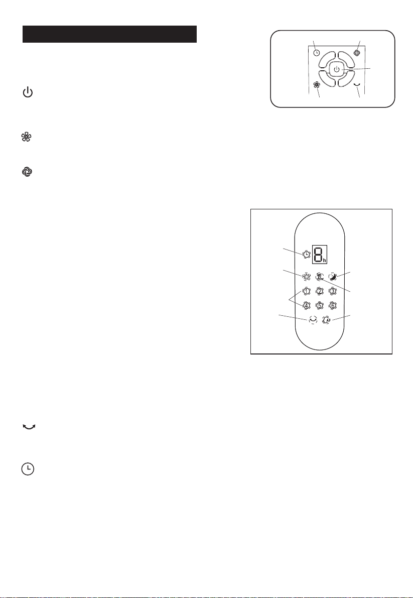
OPERATING INSTRUCTIONS
Fig. 8
Timer
Wind Mode
CONTROL PANEL
There are 5 operating keys. (See Fig.8)
- Power Key
With the unit plugged in, press to turn the fan on.
Press again to turn fan off.
TOUCH KEY
ON / OFF
OscillationWind Speed
Speed Key
Press to change the fan speed in the order “1-2-3-4-5-6”
Mode Key
Press to select mode (or wind type). Press repeatedly to change in order: “Normal
- Natural - Sleep - Smart”. Corresponding indicator will be displayed on the screen.
Features of the four modes:
Normal: delivers air constantly at set speed.
There are total of 6 speeds.
Natural: delivers air according to preset program,
8 hours timer
switching through different speeds to simulate
natural wind. There are 3 speeds under this mode.
Normal wind
Sleep wind
Sleep: similar to Natural mode but steps down
gradually for light and soft wind delivery. There are
3 speeds under this mode.
Smart: based on current fan speed and room
6 speed setting
Oscillating
Natural wind
Smart wind
temperature when this mode is selected, unit
will automatically increase or decrease fan speed
according to room temperature increase or
decrease of 1°F. When room temperature falls
below 68°F, fan will stop running and the “Smart”
DISPLAY
icon on the display will ash. Once room temperature reaches or surpasses 68°F,
fan will automatically resume running.
CAUTION: These are features designed for your comfort, not a malfunction.
OSC Key
Press to oscillate the fan left and right, the oscillating indicator will illuminate.
Press again to stop the fan from oscillating.
TIMER Key
Press to set timer-off: 1H, 2H, 4H and 8H. Once set, the timer display will indicate
set time. As time passes, display will indicate how many hours remaining in the
sequence of “8-4-2-1”. For example, if timer is set for eight hours, after one hour,
the display will still indicate “8h”. However, once the remaining time reaches 4
hours, display will change to “4h”, etc.
4
Page 5
Safety Touch Stop Sensor
This feature is designed to protect children. Fan will stop with a touch on the
fan guard. This is a protection feature and not a malfunction.
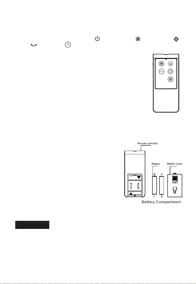
REMOTE CONTROL
Keys on the remote control: Power ( ), Wind Speed ( ), Wind Mode ( ),
OSC ( ) and Timer ( ) have the same functions as corresponding keys on
the unit. (Fig. 9)
1. Remote Control Operation
• Point the remote control at the control panel and press
the desired key.
• Make sure to align the emitter at the front of the remote
control to the receiving window on the panel.
• Avoid direct sunlight onto the control panel, this may
affect how well the remote control works.
2. Batteries (not included)
• Slide off the battery compartment cover located at the
back of the remote.
• Insert batteries and make sure the batteries are placed
as shown in Fig. 10.
• Replace battery cover.
NOTE: use size “AAA” manganese or alkaline batteries.
WARNING:
• Do not dispose batteries in re or high heat
locations, batteries may explode or leak.
• Do not mix old and new batteries.
• Do not mix alkaline, standard (carbon-zinc) or
rechargeable (nickel-cardmium) batteries.
Fig. 9
TILT ADJUSTMENT
To adjust airow upwards or downwards, push
the head gently to desired angle.
HEIGHT ADJUSTMENT
Loosen the height adjustment ring and adjust
the internal pole to desired height. Tighten the ring when done (Fig. 3)
Fig.10
CLEANING
1. Be sure to unplug from the electrical supply source before cleaning.
2. Plastic parts can be cleaned with mild soap and a damp cloth or sponge.
Follow with clean damp towel to remove soap lm.
3. Be sure water or other liquid does not come in contact with the motor.
5
Page 6

Your Guarantee
If this product is found to be faulty as a result of faulty materials or workmanship within
one year from date of purchase, it will be repaired free of charge.
This guarantee is subject to the following terms:
Sunpentown must be notied of the fault.
Proof of purchase must be presented to Sunpentown's nominated
representative.
The warranty will be void if the product if modied, misused or repaired by an
unauthorized person.
The warranty after repair will not be extended beyond the original one-year
period.
All replacement parts will be new or reconditioned.
Parts, which are replaced, become the property of Sunpentown.
The warranty applies for the use of the product in the USA only.
What is NOT COVERED:
Warranty does not include freight charges.
Damage due to installation error, product abuse and/or misuse.
Incidental or consequential damage caused by possible defects with this
product.
Labor cost incurred for the installation and/or removal of a possible defective
unit.
Damage to product caused by improper power supply voltage, accident, re,
oods or acts of nature.
Failure of product resulting from unauthorized modications to the product.
Improper installation or failure to perform the necessary maintenance.
Normal wear and tear on parts or replacement of parts designed to be
replaced.
Damage to personal property from use of product.
Replacement or repair of household fuses, circuit breakers, wiring or plumbing.
This GUARANTEE is in addition to your Statutory Rights
SUNPENTOWN INTERNATIONAL INC.
14625 Clark Ave. City of Industry, CA 91745
Tel: 800-330-0388
service@sunpentown.com
www.sunpentown.com
6
 Loading...