

Page 1
Thanks for choosing
Sun Path Products, Inc.
Home of the
We’re dedicated to making the
industries best harness/container.
EVERYTIME!
4439 Skydive Lane Zephyrhills, Fl 33540 USA4439 Skydive Lane Zephyrhills, Fl 33540 USA
4439 Skydive Lane Zephyrhills, Fl 33540 USA
4439 Skydive Lane Zephyrhills, Fl 33540 USA4439 Skydive Lane Zephyrhills, Fl 33540 USA
REVISON: 01 - ISSUE: 01
4439 Skydive Lane Zephyrhills, FL 33540 USA • Phone (813) 782-9242 Fax (813) 788-3057 • Web Site www.sunpath.com
1
Page 2
SERIAL #
CONTAINER SIZE
YOKE
HARNESS
LATERAL
LEGPAD
P.O. #
Sun Path Products, Inc.
4439 Skydive Lane Zephyrhills, Fl
33540 USA
www.sunpath.com
2
Page 3
JAVELIN OWNERS MANUAL
TABLE OF CONTENTS
WARNING.....................................................................................................
INTRODUCTION...........................................................................................
PAR TS LIST..................................................................................................
MAIN PACKING INSTRUCTIONS...............................................................
KILL LINE INSTRUCTIONS.........................................................................
THROW-OUT PILOT CHUTE PACKING INSTRUCTIONS.......................
PULL-OUT CHUTE PACKING INSTRUCTIONS........................................
RAM-AIR RESERVE PACKING INSTRUCTIONS ......................................
ROUND RESER VE PACKING INSTRUCTIONS ........................................
RESERVE STATIC LINE (RSL)....................................................................
4
5
6
7
10
11
17
19
25
31
3-RING RELEASE.........................................................................................
REQUIRED PERIODIC MAINTENANCE FOR THE 3-RING.....................
BEFORE USING THE J AVELIN...................................................................
DONNING THE JAVELIN..............................................................................
MAIN DEPLO YMENT....................................................................................
RESERVE DEPLOYMENT(PARTIAL MALFUNCTION).............................
RESERVE DEPLOYMENT (TOTAL MALFUNCTION)................................
COPYRIGHT 1987, 1988; SUN PATH PRODUCTS INCORPORA TED. ALL RIGHTS RESER VED
4439 Skydive Lane Zephyrhills, FL 33540 USA • Phone (813) 782-9242 Fax (813) 788-3057 • Web Site www.sunpath.com
3
33
36
37
38
39
39
40
Page 4
The purpose of this manual is to acquaint the rigger and prospective user with the
functions, packing procedures and other features of the JAVELIN harness/container
system. It is NOT intended to be a course in parachute jumping. This manual should be
read and understood by anyone who intends to use a JAVELIN system for sport
parachuting, however, it is the responsibility of the owner to be sure that the JAVELIN is
correctly assembled, packed, maintained and used. It is also the jumper's own
responsibility to assure that he is qualified for participation in sport parachuting activities.
(Any gender references automatically refers to the user)
For more inf ormation on the Javelin Harness & Container System and general information
about Sun Path Products, Inc. please check out our web site at http://www.sunpath.com
!!! W ARNING !!!
Parachuting is a hazardous activity and there are dangers which sometimes cannot be
foreseen. No one should attempt to make a parachute jump unless they have been
thoroughly trained by an experienced and qualified instructor. There are no guarantees
that any equipment will function as intended, regardless of how it is assembled, packed,
maintained or used. Serious injury or death can result from the use, misuse, or attempted
use of any parachute equipment.
!!! THE USER ASSUMES ALL RISKS !!!
4
Page 5

INTRODUCTION
The JAVELIN and JAVELIN Odyssey is a spor t parachute harness/container system
featuring back mounted main and reserve canopy containers. The reserve container
is characterized by the partially exposed top plate of the reserve pilot chute, which is
packed on top of the side flaps.
The JAVELIN is equipped with the 3-Ring release system under a license agreement
with The Relative Workshop Incorporated. Other standard features include throw-out
hand deployed main pilot chute, single-pin reserve closure, step-in leg straps and
"wrap around" harness construction. This type of harness construction produces
junctions which are not limited to the strength of the stitches. In the JAVELIN, the
harness junctions are stronger than the webbing itself.
The JAVELIN Odyssey includes new features such as “Quilted look” Cut-in Backpad,
Split legstraps, anti-twist riser tubes, new fabric options, housing clamps and large
Odyssey logos on the main riser covers.
The reserve container will accept either a round or ram-air reserve canopy. For ramair reserves, the JA VELIN is supplied with the unique "MOLAR-BA G", a free-bag which
features zero thickness where the closing loop passes through it, eliminating the
need for any preliminary fid or preliminary pull-up cord when packing the canopy into
it. This also prevents any of the canopy fabric from coming into contact with the
closing loop.
Design and testing of the JA VELIN was accomplished over a period of eighteen months
and has resulted in one of the most "RIGGER FRIENDLY" systems on the mar ket.
There is no additional sewing or tacking required to assemble the JAVELIN with
canopies and no "special techniques" are necessary to pack it. An FAA certified
rigger with current skills should be able to assemble and pack the JA VELIN b y following
the instructions in this manual.
The JAVELIN harness/container system was tested in accordance with
AS-8015A and is approved by the FAA under TSO C-23c, Category B.
In October 2001 the Javelin har ness/container was retested in accordance with
AS-8015B and is approved under TSO C-23d for:
a maximum operating exit weight of 300lbs (136 kg) and
a maximum operating speed of 170 knots (198 mph or 330 kph).
4439 Skydive Lane Zephyrhills, FL 33540 USA • Phone (813) 782-9242 Fax (813) 788-3057 • Web Site www.sunpath.com
5
Page 6

PARTS LIST
The JAVELIN is shipped to the customer with the following components:
HARNESS/CONTAINER
MAIN RISERS WITH CONTROL TOGGLES
MAIN DEPLOYMENT BAG
RELEASE HANDLE (CUTAWAY HANDLE)
MAIN PILOT CHUTE AND BRIDLE
RESERVE PILOT CHUTE WITH:
*
BRIDLE FOR ROUND RESERVE
-orBRIDLE AND "MOLAR" FREE-BAG FOR RAM-AIR RESERVE
**
RESERVE RIPCORD
***
RESERVE CONTROL TOGGLES
MAIN CLOSING LOOP
RESERVE CLOSING LOOP (CYPRES)
ONE EXTRA CLOSING LOOP(MAIN)
RUBBER BANDS
RESERVE PACKING DATA CARD
JAVELIN OWNER'S MANUAL
Only the JAVELIN reserve pilot chute may be used with the JAVELIN harness/
*
container system. Do not substitute any other pilot chute.
Only the "molar free-bag may be used when packing a ram-air reserve canopy into
**
the JAVELIN harness/container system.
All JAVELINS are manufactured ready to accept the Cypres A.A.D.
Only Javelin reser ve ripcords to be used.
***
All components listed above are also available individually from:
SUN PATH PRODUCTS, INC.
4439 SKYDIVE LANE
ZEPHYRHILLS, FL 33540 USA
(813) 782-9242
[email protected]
6
Page 7
MAIN PACKING INSTRUCTIONS
This chapter deals with the procedures f or packing the a r am-air main canop y into the
JAVELIN harness/container system. Assembly and packing of the main must be done
by an FAA certified rigger or by the person making the jump.
1. Carefully inspect the main canopy, suspension lines, control lines, slider and
grommets, connector links, etc., bef ore assembling it with the risers. Replace or repair
any worn or damaged parts. Also inspect the deployment bag, bridle and pilot chute.
2. Attach the main canopy to the main risers, being sure that the canopy is facing the
same direction as the harness/container system and that each suspension line is clear
from its attachment point all the way through the slider g rommet to the connector link
without passing around any other line. Be sure the control lines are clear from the
trailing edge of the canopy through the slider grommets and through the ring guides
on the rear risers to the control toggles. Each control toggle m ust be
to its control line at the location specified by the canopy manufacturer. Also be sure
that the connector links are tight enough so that they cannot be loosened with the
fingers alone. Also refer to the canopy manufacturers owners manual.
SECURELY
tied
3. Pass the pilot chute bridle down through the grommet in the top of the deployment
bag and attach it to the ring on the top of the main canopy. Be sure that the stop-ring
on the bridle is between the bag and the pilot chute.
For kill line attachment and cocking of the kill line pilot chute refer to instructions
on page 10.
4439 Skydive Lane Zephyrhills, FL 33540 USA • Phone (813) 782-9242 Fax (813) 788-3057 • Web Site www.sunpath.com
7
Page 8
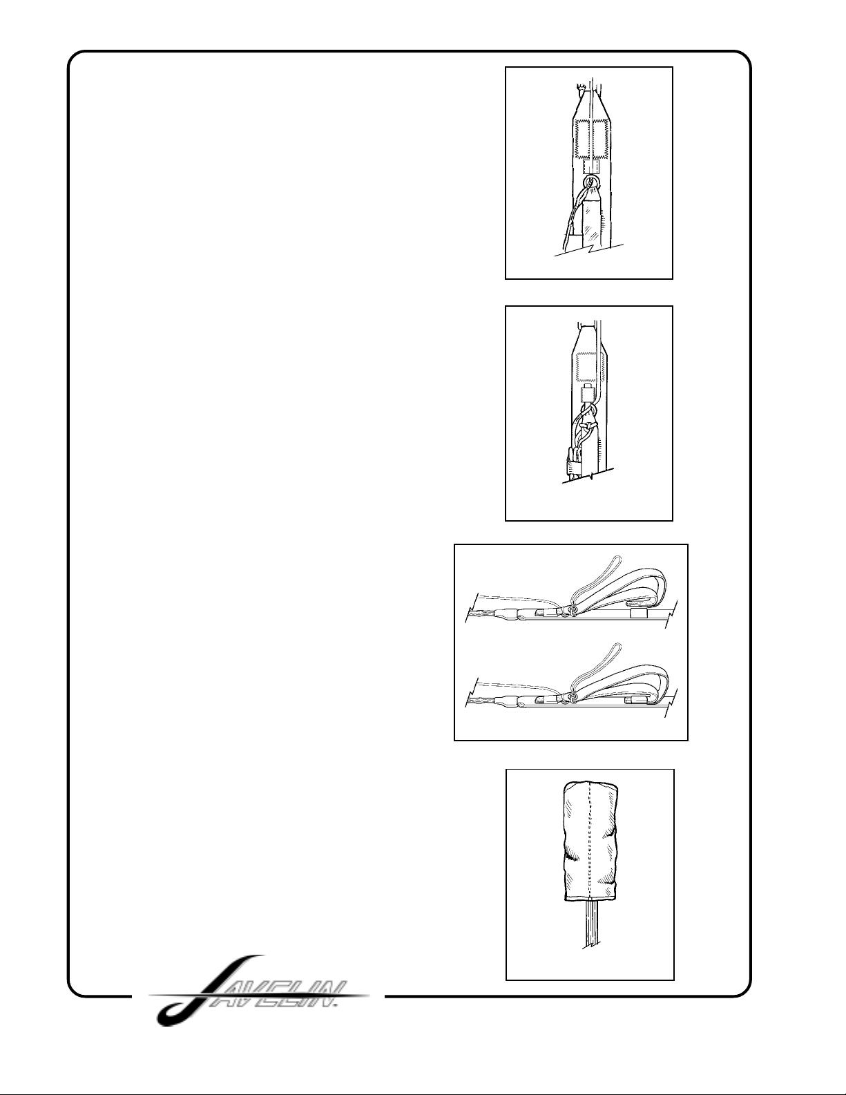
4. Set the deployment brakes on each
side by pulling the control line down
through the guide ring until the brake
loop just passes through the guide
ring (FIG. 1).
Insert the stiffened upper portion of the
toggle through the loop and insert the
upper portion into the elastic keeper,
pull the control line back up tightly
against the guide ring. (FIG. 2).
FOR VELCRO T OGGLE
S fold the slack between the toggle and
the brake set and stow it in the Velcro
loop provided, then mate the Velcro on
the riser.
FOR NO VELCRO TOGGLE
Next insert the stiffened lower portion
of the toggle into the elastic keeper in
the same direction as the top portion
(from the bottom of the riser towards
the top). (FIG. 3).
FIG. 1
FIG. 2
5. At this point, refer to the directions
by the canopy manufacturer for
flaking and folding the canop y. After
flaking and folding it should
resemble (FIG. 4).
Be sure the slider is up as far as it
will go against the canopy.
“Cock the Kill Line Pilot Chute”,
before placing the canopy in the main bag!
Kill Line Instructions refer to page (10)
FIG. 3
FIG. 4
8
Page 9
6. Stack the canopy in "S" folds as
shown in (FIG. 4).
Keeping the slider up against the canop y
and keeping the slack out of the lines.
The stacked canopy should be 3-4
inches wider than the bag.
7. Pull the bag down onto the canopy.
Try to fill the corners and sides of the
bag to distribute the bulk evenly and
avoid forming a lump in the middle.
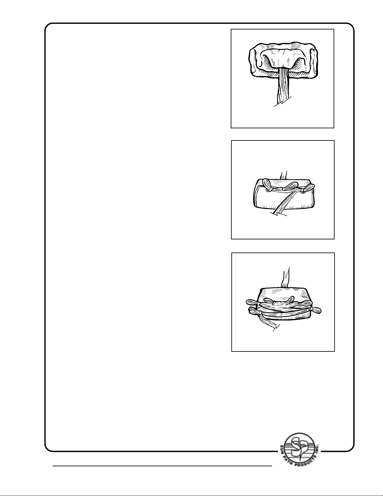
8. Mate the locking stows with the
suspension lines to close the mouth of
the bag. Center locking stow, to be
stowed first (FIG. 5).
During this part of the packing
procedure always make sure that the
rubber bands used for the locking stows
are strong and in good condition. The
weight of the canopy inside the bag
comes to bear on these locking stows
when the canopy is lifted off the jumper's
back during deployment and a broken
locking stow at this point may result in
an out-of-sequence deployment.
FIG. 4
FIG. 5
9. Pull the bridle out from the top of the
bag until the metal ring of the canopy is
seated against the grommet of the bag.
Be sure there is no canopy fabric
between the ring and the grommet. Now
stow the remainder of the suspension
lines across the bottom of the bag in the
rubber bands at each end. Make line
stows as per canopy manufacturers
recommended size/length. Leave 12" to
15" of lines unstowed between the bag
and the connector links. (FIG. 6).
4439 Skydive Lane Zephyrhills, FL 33540 USA • Phone (813) 782-9242 Fax (813) 788-3057 • Web Site www.sunpath.com
9
FIG. 6
Page 10
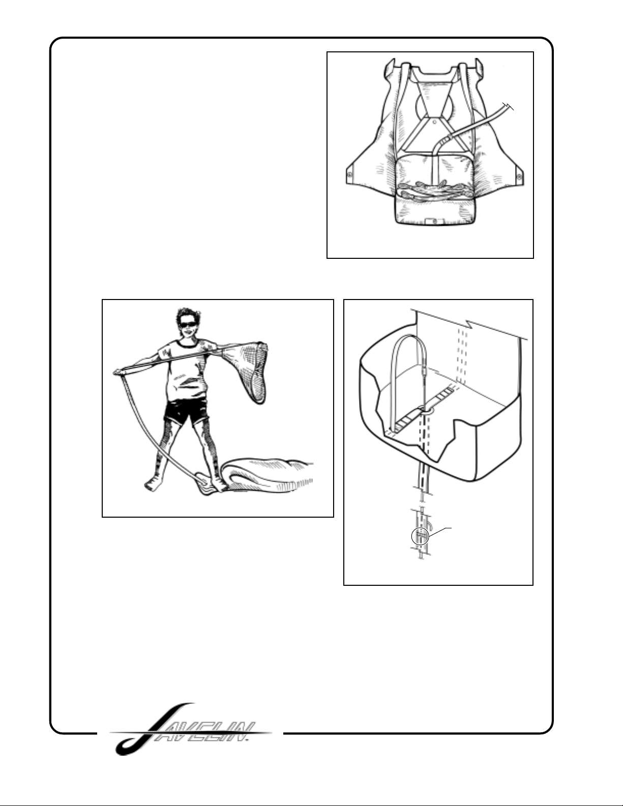
10. Lay the risers in the
"trough" between the sides of
the reserve container and the
riser covers. Don’t wrap the
lines and risers around
reserve pack tray. Place the
bag in the container with the
line stows toward the bottom.
This position is important; if
the line stows are toward the
top, it ma y be more difficult for
the pilot chute to extract the
bag (FIG. 7).
FIG. 7
FIG. 1
kill-line window
FIG. 2
KILL-LINE INSTRUCTIONS
(Sun Path Products, Inc. does not recommend the use of zero-p pilot chutes)
The pilotchute should be “cocked” before placing the canopy into the deployment
bag. To do this simply anchor the bag (your foot works great) and pull out on the
pilotchute handle until the center line is tight (FIG. 1).
To double check that you have fully cocked the pilotchute, check to see that the
green portion of the kill-line is visible in the window on the bridle (FIG. 2).
10
Page 11
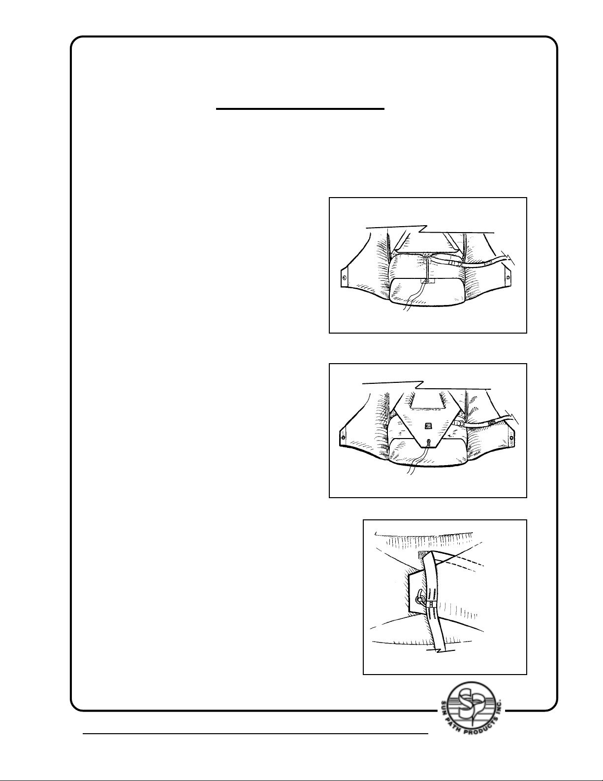
FOR JAVELINS EQUIPPED WITH A PULL-OUT
PILOT CHUTE SKIP TO PAGE 17
JAVELINS EQUIPPED WITH A THROW-OUT PILOT
CHUTE
11. Thread the pull-up cord through the
closing loop and bring the closing loop
over the top of the bag. The bridle should
be routed to the right of the closing loop.
Thread the pull-up cord through the
bottom flap grommet and close the
bottom flap (FIG. 8).
FIG. 8
12. Close the top flap, keeping the bridle
to the right (FIG. 9).
13. Mate the velcro on the bridle just
above the curved pin, to the velcro on
the top flap. Close the left side flap , then
the right side flap, inserting the curved
pin attached to the bridle into the closing
loop. Remove the pull-up cord SLOWLY
to avoid wearing the loop. This is very
important: it assures that the pilot chute
bridle will have sufficient slack to extract
the curved pin (FIG. 10).
FIG. 9
FIG. 10
4439 Skydive Lane Zephyrhills, FL 33540 USA • Phone (813) 782-9242 Fax (813) 788-3057 • Web Site www.sunpath.com
11
Page 12
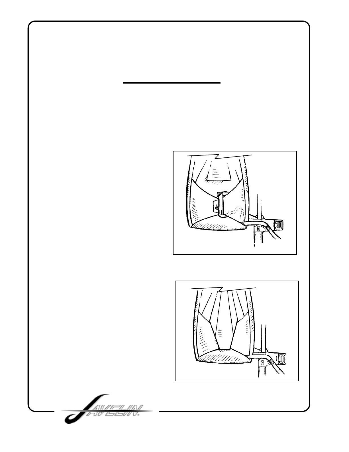
FOR JAVELINS EQUIPPED WITH A BOTTOM OF
CONTAINER (BOC) THROW-OUT PILOT CHUTE
SKIP TO P AGE 15
JAVELINS EQUIPPED WITH A REAR OF LEG
(ROL) THROW-OUT PILOT CHUTE
14. Mate the velcro on the bridle to the
velcro on the lower right side of the main
container, harness-lateral and leg pad.
The excess bridle between this velcro
and the curved pin should now be tucked
under the right side flap (FIG. 11).
15. Close the top flap protector by
tucking the "tongue" underneath the
closed flaps (FIG. 12).
At this point be sure that the bridle goes
from the container to the pilot chute
without passing under or through any
part of the har ness. Bridle velcro to be
mated to velcro along side of container.
FIG. 11
FIG. 12
12
Page 13
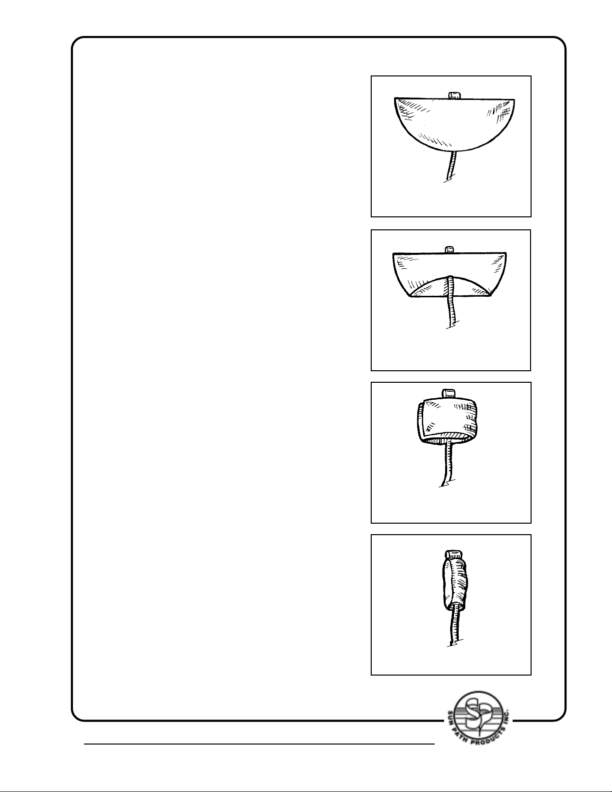
16. Lay the pilot chute out flat with the
mesh side up. Fold the e xcess bridle on
top of the laid out parachute and fold the
pilot chute in half over the bridle
(FIG. 13).
Fold the curved side up about 4" (FIG. 14).
FIG. 13
FIG. 14
17. Fold the pilot chute into thirds (FIG. 15).
Roll it tightly into a cylindrical shape (the
tighter the better) (FIG. 16).
4439 Skydive Lane Zephyrhills, FL 33540 USA • Phone (813) 782-9242 Fax (813) 788-3057 • Web Site www.sunpath.com
FIG. 15
FIG. 16
13
Page 14
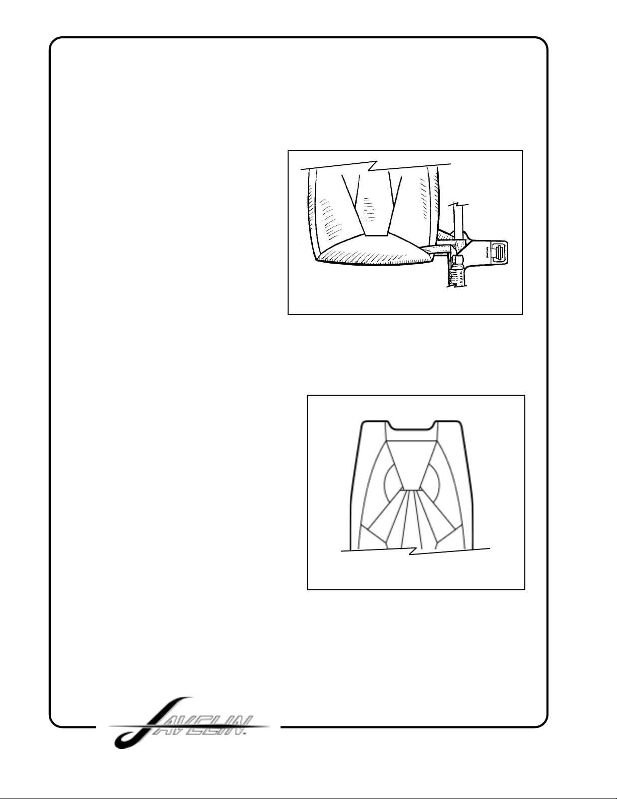
18. Stuff the rolled pilot chute
completely into the pouch, making sure
that the handle sticks out the top for an
easy grip (FIG. 17).
19. Close the riser covers ov er the main
risers (FIG. 18).
FIG. 17
14
FIG. 18
Page 15
JAVELINS EQUIPPED WITH A BOTTOM OF
CONTAINER (BOC)
THROW-OUT PILOT CHUTE
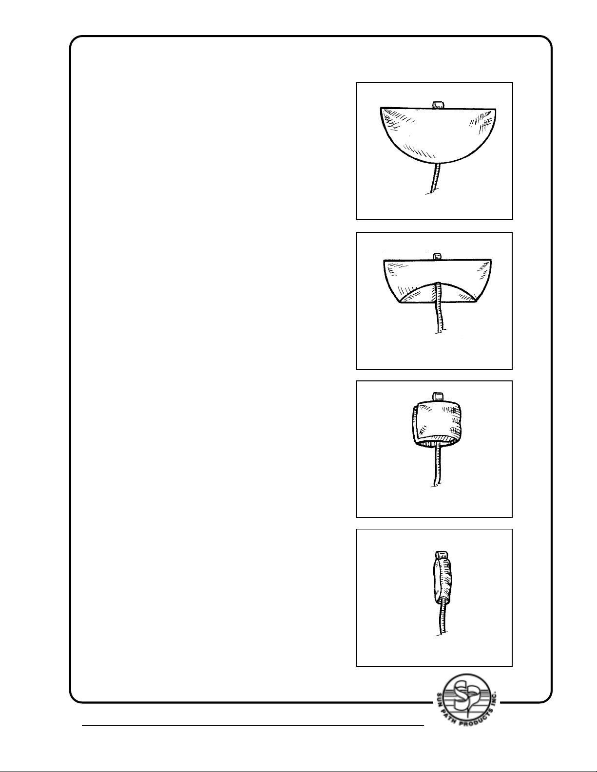
1. Lay the pilot chute out flat with the
mesh side up. Fold the e xcess bridle on
top of the laid out parachute and fold the
pilot chute in half over the bridle
(FIG. 1).
Fold the curved side up about 4" (FIG. 2).
FIG. 1
2. Fold the pilot chute into thirds (FIG. 3).
Roll it tightly into a cylindrical shape (the
tighter the better) (FIG. 4).
FIG. 2
FIG. 3
4439 Skydive Lane Zephyrhills, FL 33540 USA • Phone (813) 782-9242 Fax (813) 788-3057 • Web Site www.sunpath.com
15
FIG. 4
Page 16
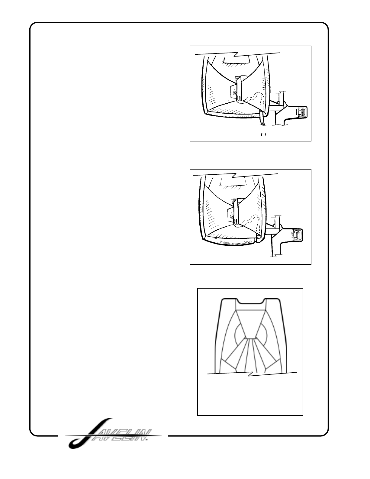
3. Tuck about 12 inches of bridle under
the right flap being sure to make it snag
proof and secure (FIG. 5).
4. Stuff rolled pilot chute completely into
pouch making sure the handle sticks out
enough for an easy grip. Place any
exposed bridle under the bridle cover
leading to the spandex pocket. (FIG. 6).
FIG. 5
5. Close riser covers over the main risers
(FIG. 7).
FIG. 6
FIG. 7
16
Page 17
THIS SECTION IS FOR PULL-OUT
PILOT CHUTE ONLY
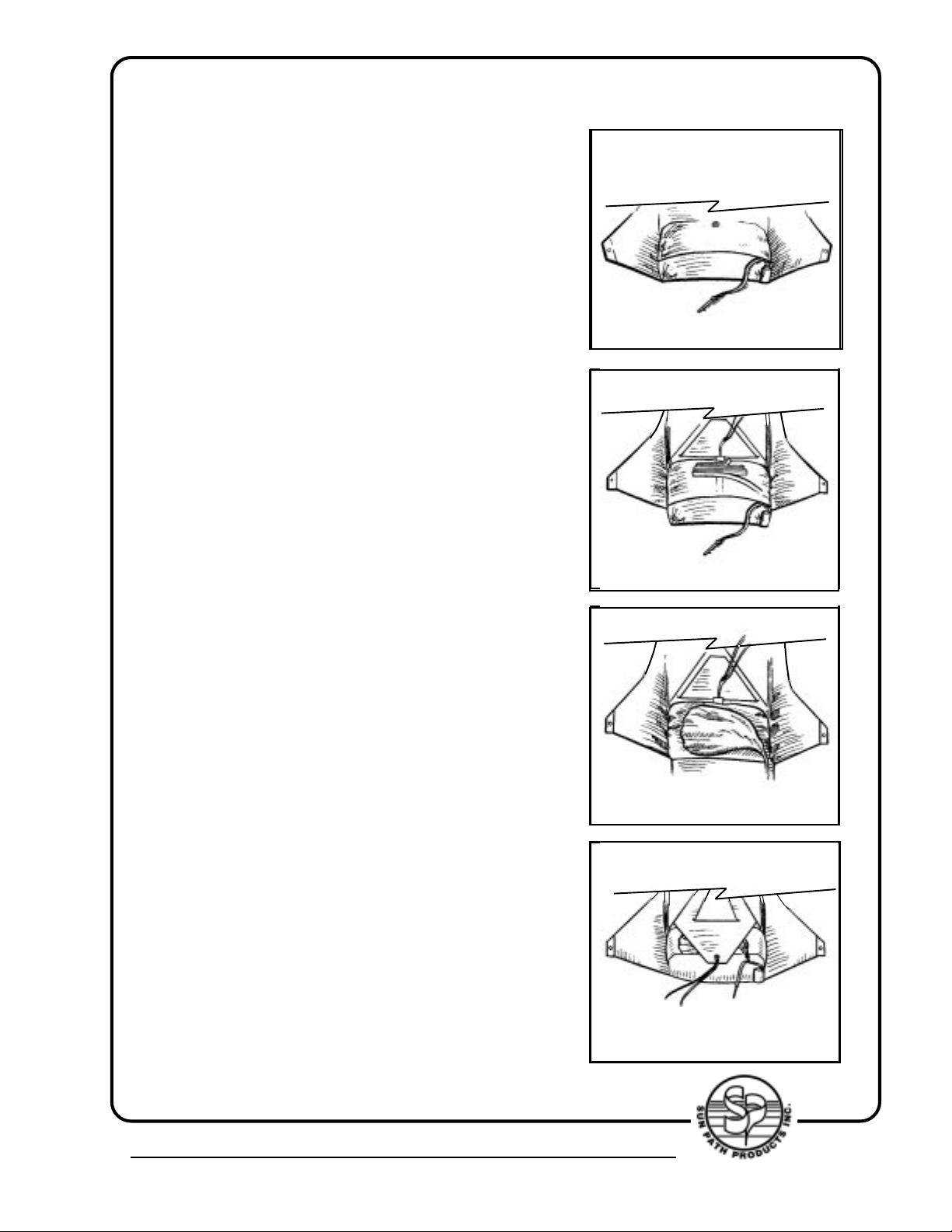
1. Mate the velcro of the pull-out pad
with the velcro under the pull-out pad
cover . It’ s located at the right hand corner
of the bottom flap (FIG. 1).
2. Thread the pull-up cord through the closing
loop and lay it back across the reserve
container temporarily to keep it out of the wa y .
Arrange the bridle in folds 6 to 8 inches long.
Lay the f olded bridle across the upper part of
the bag as shown in (FIG. 2).
Be sure NOT to tuck these folds down
between the bag and the bottom of the
reserve container. To do so may retard the
action of the pilot chute.
FIG. 1
FIG. 1
FIG. 2
FIG. 2
3. Loosely fold the pilot chute and lay it across
the bag as shown in (FIG. 3).
4. Close the bottom flap then the top flap.
(FIG. 4).
4439 Skydive Lane Zephyrhills, FL 33540 USA • Phone (813) 782-9242 Fax (813) 788-3057 • Web Site www.sunpath.com
FIG. 3
FIG. 3
FIG. 4
17
Page 18
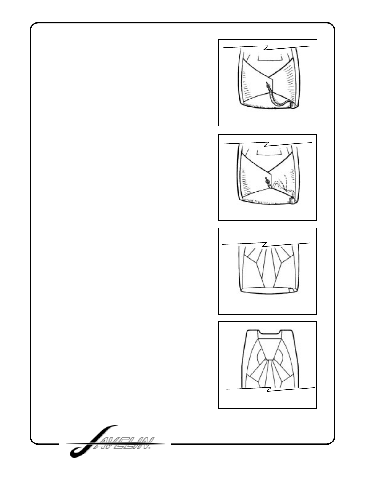
5. Close the right side flap then the left
side flap. Secure the closing loop with
the pin (FIG. 5).
6. Tuck the slack in the tape under the right
side flap (FIG. 6).
FIG. 5
FIG. 6
7. Close the top flap protector by tucking the
“tongue” underneath the flaps (FIG. 7).
8. Close the riser covers over the main risers
(FIG. 8).
FIG. 7
FIG. 8
18
Page 19

RAM-AIR RESERVE PACKING INSTRUCTIONS
This chapter deals with the procedures for packing a r am-air reserve canop y into
the JAVELIN harness/container system. Assembly and packing of the reserve must
be accomplished by an FAA certified Senior Rigger or Master Rigger, or by the
manufacturer of the harness/container system.
Helpful Hint:
type of canopy, S/N and DOM from canopy data panel.
REQUIRED TOOLS:
One adjustable wrench
One temporary pin (preferably with warning flag attached)
One pull-up cord (48" minimum length) (cypres pull-up cord recommended)
One packing paddle or "long bar"
.22 calibre rifle cleaning rod or "T" bar
Two 6 inch strips of 1" velcro loop (with warning flag attached)
Optional tool - knee plate
1. Make a thorough inspection of all components of the reserve parachute
a) Reserve pilot chute
b) Reserve bridle
c) Free-bag (“molar” bag)
d) Reserve canopy, lines, slider, connector links
e) Harness/container system
Before starting to pack using your riggers log book copy down
2. Follow the canopy manufacturer's directions for the inspection, attachment to
risers, routing of control lines, attachment of control toggles, setting deployment
brakes and for flaking and folding the reserve canopy.
4439 Skydive Lane Zephyrhills, FL 33540 USA • Phone (813) 782-9242 Fax (813) 788-3057 • Web Site www.sunpath.com
19
Page 20
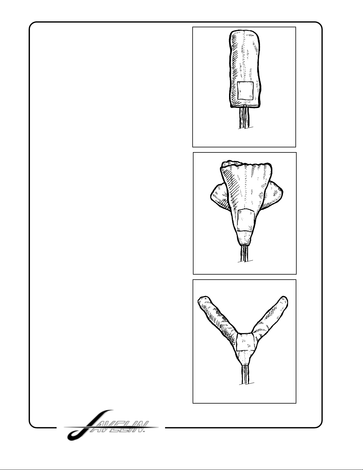
3. If the manufacturer of the ram-air
reserve canopy uses a "conventional"
packing method, the canopy should
look similar to (FIG. 1). after it has been
flaked and folded.
If the manufacturer of the ram-air reserve
canopy recommends the "PRO-PACK",
the canopy will resemble (FIG. 2).
SUN PATH HIGHLY RECOMMENDS
THE "PRO-PACK" FOR ALL RAM-AIR
RESERVES PACKED INTO THE
JAVELIN HARNESS/CONTAINER
SYSTEM.
FIG. 1
In either case, it will be necessary at this
point to spread the top end of the canopy
into halves by pushing down into the
center from the top and spreading it
outward into a "V" shape. (FIG. 3)
To keep the canopy symmetrically
divided, use the seam in the top of the
center cell as a reference. At this point
be sure that the slider is as far up as it
will go against the slider stops.
FIG. 2
FIG. 3
20
Page 21
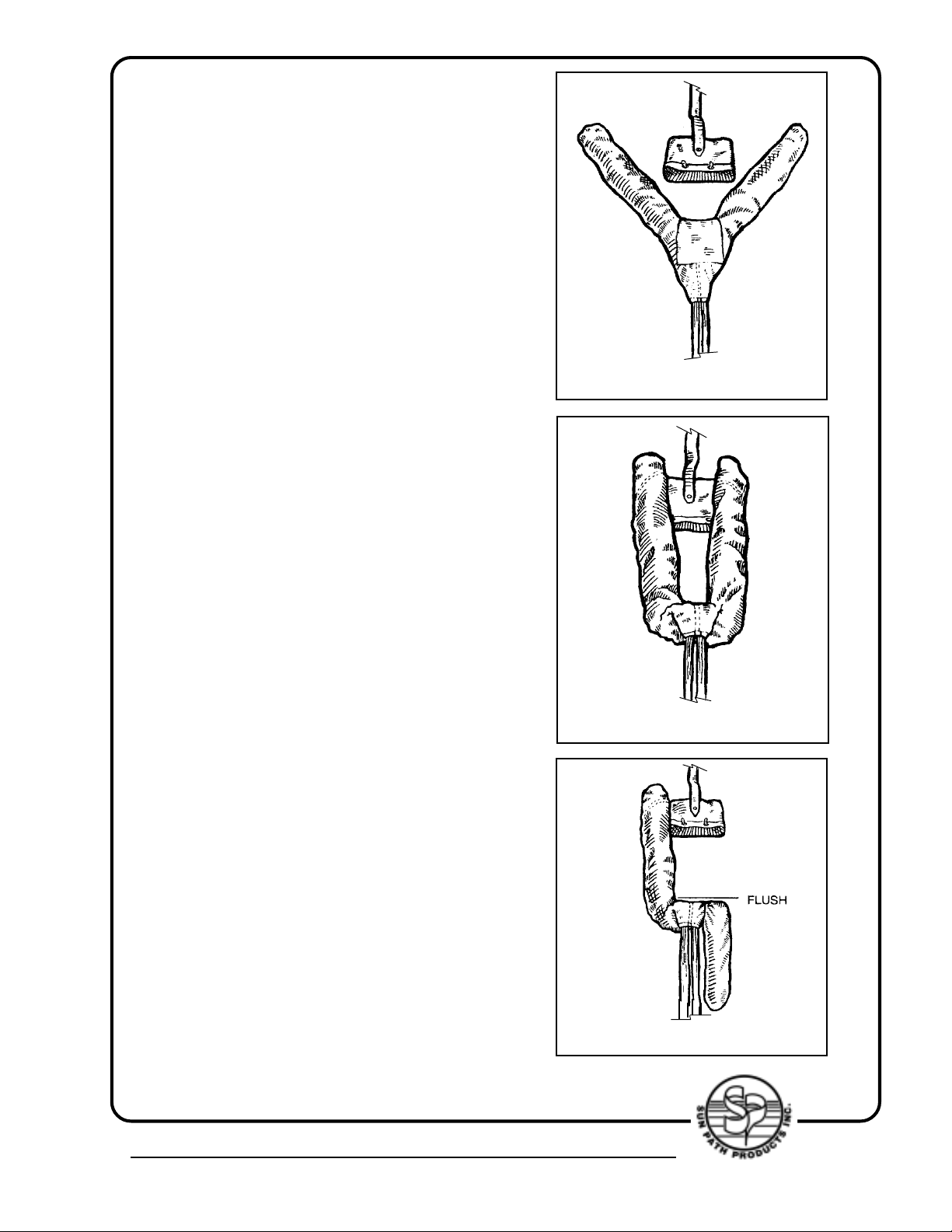
4. Place the reserve deployment bag in
the "V" formed by the canopy as shown
in (FIG. 4).
Do not use any other deployment bag.
Only the JAVELIN "molar" bag may be
used in the JAVELIN harness/container
system.
5. “S” fold the bottom of the canopy and
slider up on top of itself (FIG 5).
FIG. 4
6. With left knee , kneel on the “S” f olded
portion of the canopy and fold the right
hand ear all the way back. Make the fold
flush with the top of the canopy (FIG 6).
FIG. 6
4439 Skydive Lane Zephyrhills, FL 33540 USA • Phone (813) 782-9242 Fax (813) 788-3057 • Web Site www.sunpath.com
FIG. 5
21
Page 22
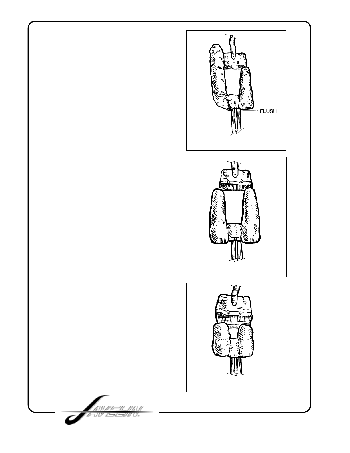
7. Now fold right hand ear forward,
making fold flush with bottom of canopy
(FIG. 7).
8. Change knee and repeat steps 6 and
7 with left hand ear (FIG 8).
FIG. 7
9. Kneel on both ears at bottom of
canopy ("S" folded portion) and
fold both ears underneath
themselves, so that the top of the
ear is flush with the top of the
canopy (FIG 9).
FIG. 8
FIG. 9
22
Page 23
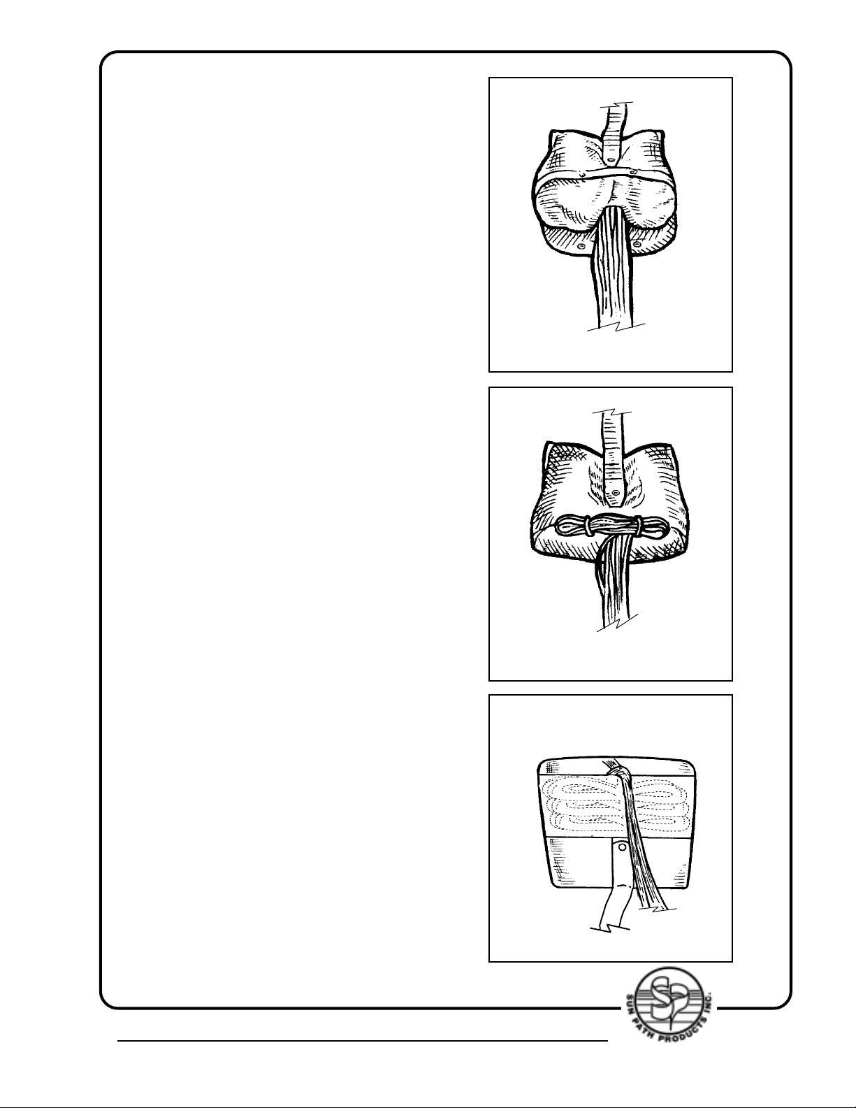
10. Place ears into top corners
of the free bag (FIG. 10). Place main
bulk of canopy into the remainder of the
free bag.
11. Lock the mouth of the free bag by
making two stows with the suspension
lines in the "Safety Stow". (This is the loop
made of 1/8" shock cord) (FIG 11).
Javelin “Safety stow” must be used-use
of any other may void TSO.
FIG. 10
12. After the two locking stows are
FIG. 11
made, stow the remainder of the
suspension lines (to with-in 6” of the
connector links) in the line-stow
pouch on the back of the bag. This is
where it is useful to use the velcro
strips mentioned in the list of tools.
Cover the hook velcro on the pouch
with the strips of loop velcro while
stowing the lines in the pouch. Make
figure of 8 folds with the lines, the
width of the pouch. To close the
pouch, remove the strips of loop
velcro and mate the velcro at the
mouth of the pouch, being sure that
FIG. 12
none of the suspension lines are
captured by the closure (FIG 12).
4439 Skydive Lane Zephyrhills, FL 33540 USA • Phone (813) 782-9242 Fax (813) 788-3057 • Web Site www.sunpath.com
23
Page 24
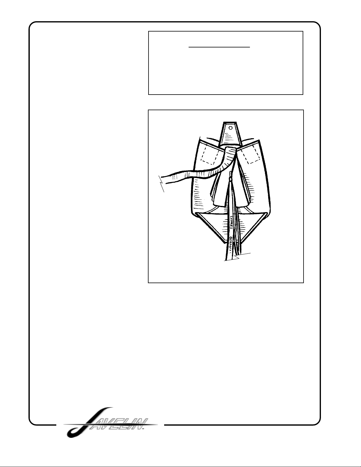
13. Lay the reserve risers in
the container so that the
connector links are in the
lower corners of the
container.
Pass the pull-up cord through
the closing loop, then thread
it through the grommet in the
free-bag. Lay the bag in the
container with the line-stow
pouch on the under side.
Close each side flap in turn,
securing the flaps with the
temporary pin. Push the tuc k
flaps under the ears of the
bag. "S" fold the bridle ev enly
up and down both sides of the
temporary pin and pull-up
cord (FIG. 13).
HELPFUL HINT
Suggested loop length for cypres
closing after setting & stretching to
be 2 1/8”
14. Pass the pull-up cord up
through the pilot chute and
out through the top plate.
This is easily accomplished
with .22 calibre rifle cleaning
rod, or with the "T" bar. Seat
the lower end of the pilot
chute on top of the side flaps
and bridle, keeping the pull-
up cord tight, compress the
pilot chute and lock it with the temporary pin. Now pull all the fabric out from under the top
plate so that the pilot chute canopy appears round. At this point check the length of the
closing loop. If the pilot chute top plate can rock back and forth or from side to side, the
loop is too long. Shorten the loop so that when the pilot chute is compressed and locked
with the temporary pin, the top plate will be firmly seated in the "nest" formed by the
"molar" shape of the bag and the side flaps.
For pilot chute closure refer to page 29.
FIG. 13
24
Page 25
ROUND RESERVE PACKING INSTRUCTIONS
This chapter deals with the procedures for packing a round reserve canopy
into the JAVELIN harness/container system. Assembly and packing of the
reserve must be accomplished by an FAA certified Senior Rigger or Master
Rigger, or by the manufacturer of the harness/container system.
Helpful Hint:
type of canopy, S/N, DOM from canopy data panel.
REQUIRED T OOLS:
One adjustable wrench or flat head screwdriver
One temporary pin (preferably with warning flag attached)
One pull-up cord (48" minimum length) (Cypres pull-up cord recommended)
One packing paddle or "long bar"
.22 calibre rifle cleaning rod or "T" bar
Optional Tool - Knee plate
1. Make a thorough inspection of all components of the reserve parachute:
a) Reserve pilot chute
b) Reserve bridle
c) Reserve canopy, lines, connector links
d) Harness/container system
2. Attach the bridle to the apex of the
reserve canopy. The smaller loop of
the bridle should be used at the apex
and the loop should be tacked securely
with enough slack so that the loop will
not bind the apex lines. The apex lines
must be able to move freely through the
bridle attachment (FIG. 1).
The large loop of the bridle must then be
attached to the pilot chute.
Before starting to pack using your riggers log book copy down
FIG. 1
4439 Skydive Lane Zephyrhills, FL 33540 USA • Phone (813) 782-9242 Fax (813) 788-3057 • Web Site www.sunpath.com
25
Page 26
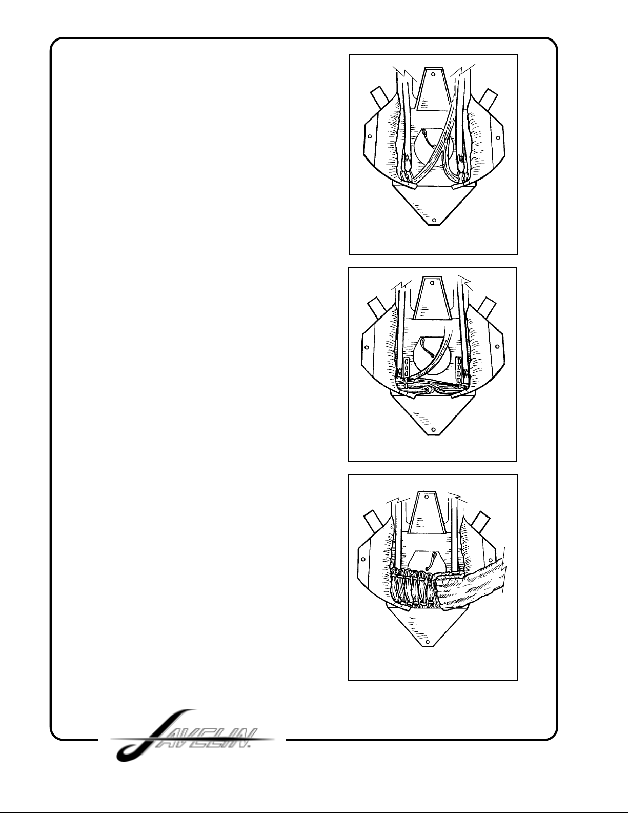
3. Follow the canopy manufacturer's
directions for the inspection, attachment
to risers, routing of control lines (if
present) and for flaking the reserve
canopy.
4a. If the canopy is equipped with a full
diaper, all sto ws of the suspension lines
will be made on the diaper. Do this in
accordance with the canopy
manufacturer's directions. La y the risers
in the reserve container so that the
connector links are in the lower corners
(FIG. 2) and go to STEP 5.
4b. If the reserve canopy has no diaper ,
or is equipped with only a partial diaper,
the suspension lines must be stowed in
the container. Lay the risers in the
container so that the connector links are
in the lower corners (FIG. 2) and make
the first stow of suspension lines in the
lower left corner. Continue upward,
making the stows the full width of the
pack tray (FIG. 3).
FIG. 2
FIG. 3
5. Place the skirt (or diaper) of the
canopy in the lower left corner of the
reserve container. If the diaper is not as
wide as the container, make a short fold
in the right side to equalize the bulk
(FIG. 4).
FIG. 4
26
Page 27
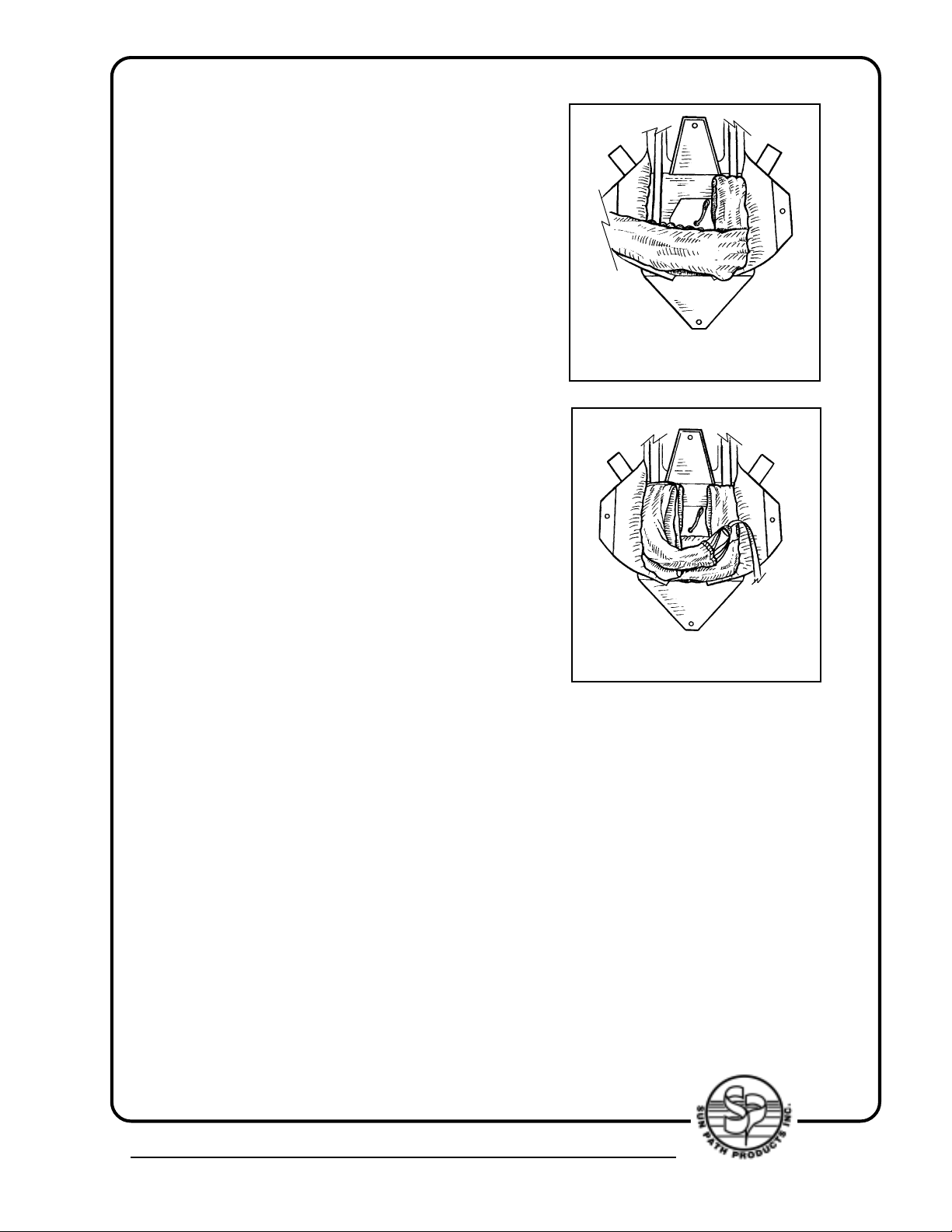
6. Fold the canopy up and down the
right side of the container, then make a
fold across the bottom of the container,
on top of the diaper or skirt (FIG. 5).
7. Make two folds up and down the left
side of the container, keeping the bulk
away from the center as much as
possible. The rigger may at this point
make another fold across the bottom in
order to distribute the bulk evenly side
to side (FIG. 6).
The object is to form a "U" shaped stack
with the canopy so that the pilot chute
will seat itself in the "nest" formed by the
side flaps after they have been closed.
FIG. 5
FIG. 6
The distribution of b ulk may vary with the
size of the canopy or the shape of the
container and it is left to the rigger's
discretion how many folds to make on
each side or how many times the canop y
may be folded across the bottom of the
container. As long as the stack is
basically "U" shaped and the bulk of the
stack is kept away from the center of the
container, the pack is more likely to be
correctly shaped after the flaps have
been closed.
4439 Skydive Lane Zephyrhills, FL 33540 USA • Phone (813) 782-9242 Fax (813) 788-3057 • Web Site www.sunpath.com
27
Page 28
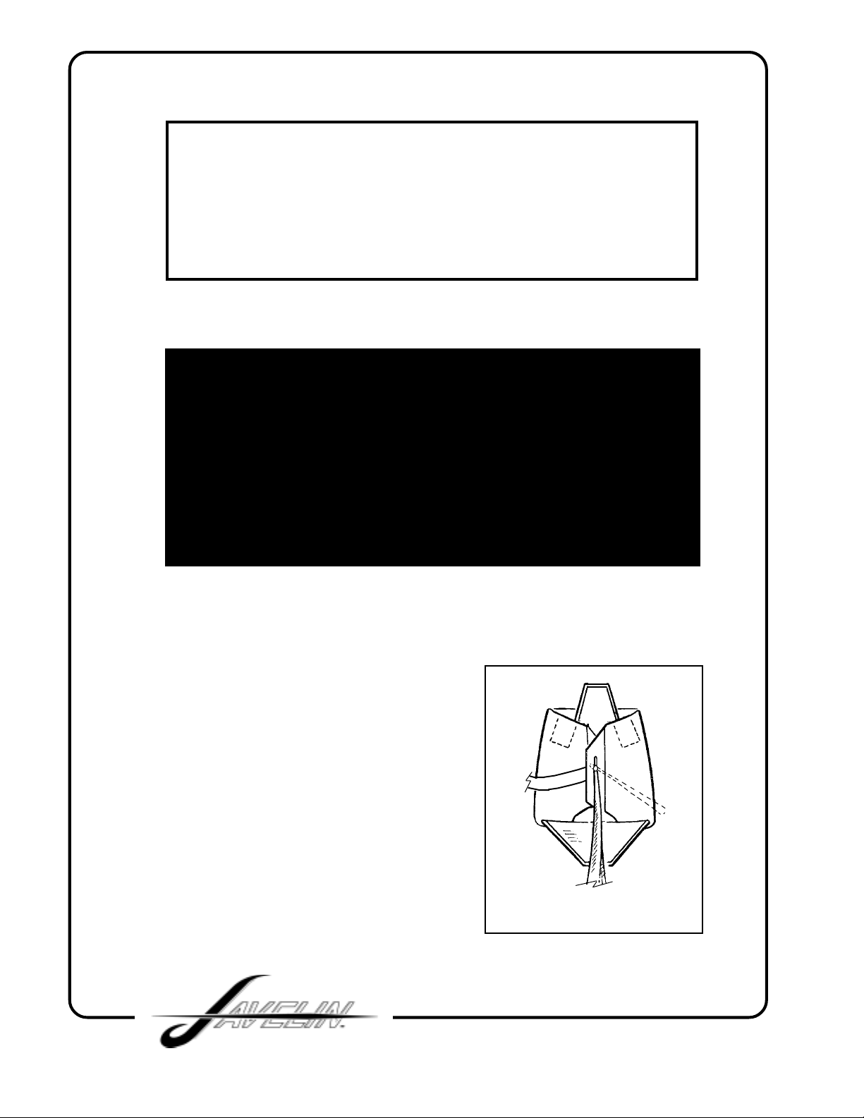
A HELPFUL HINT:
Be sure that the lower corners of the reserve container are
filled as you fold the canopy into the container. If there is slack
in the lower corners, it may be difficult to close the container or
to make the container look neat after it has been closed.
ONE NOTE OF CAUTION:
Do not stuff the apex of the canopy down into the lower
corner of the reserve container. Doing so might delay (or even
prevent) extraction of the apex by the pilot chute.
8. Thread the pull-up cord through the
closing loop and close each side flap in
turn, routing the bridle out the side of the
container. Try to keep the bulk of the
canopy away from the center of the
container while closing the side flaps.
Secure the side flaps with the temporary
pin (FIG. 7).
Then push the tuck flaps in under the
folded canopy at the upper edge of each
side flap.
28
FIG. 7
Page 29
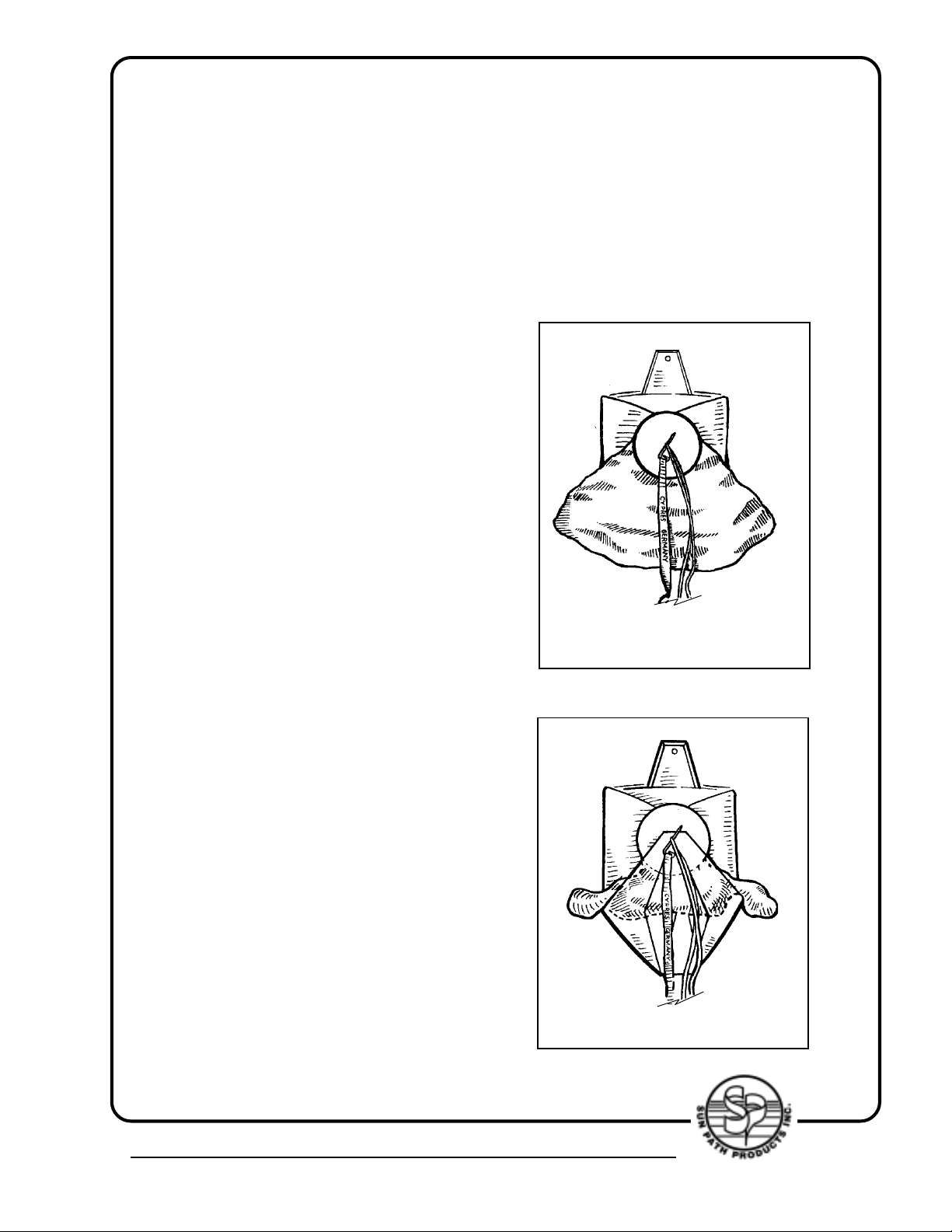
9. Pass the pull-up cord through the pilot
chute and out through the top plate. This
is easily accomplished with the .22 calibre
rifle cleaning rod or with the "T" bar, but
easier than without!! Seat the lower end
of the pilot chute on top of the side flaps,
and keeping the pull-up cord tight,
compress the pilot chute and lock it with
the temporary pin. Now pull all the fabric
out from under the top plate so that the
pilot chute canopy appears round. At this
point check the length of the closing loop.
If the pilot chute top plate can rock back
and forth or from side to side the closing
loop will need to be shortened. Shorten
the loop so that when the pilot chute is
compressed and locked with the
temporary pin, the top plate will be firmly
seated in the "nest" formed by the "U"
shape of the stacked canopy.
10. Fold the bridle of the round canopy
in accordion folds across the bottom of
the container on top of the side flaps. The
width of the folds will vary with the width
of the container; a simple rule-of-thumb
is: "make the folds as wide as possible,
but not so wide as to be seen after the
bottom flap has been closed".
FIG. 8
11. Roll or fold the pilot chute fabric at
the top of the pilot chute parallel with the
top of the container and push this roll
under the top plate of the pilot chute.
Draw the rest of the pilot chute fabric
down the sides of the pilot chute top plate
pushing the excess fabric under the pilot
chute top plate as you go (FIG. 8).
12. Fan out the pilot chute fabric,
so that it extends wider than the
bottom flap. Be sure to keep the
point of the fan narrow and tight to
the middle of the bottom of the pilot
chute top plate. Close the bottom flap
and secure it with the temporary pin.
FIG. 9
(FIG. 9).
4439 Skydive Lane Zephyrhills, FL 33540 USA • Phone (813) 782-9242 Fax (813) 788-3057 • Web Site www.sunpath.com
29
Page 30
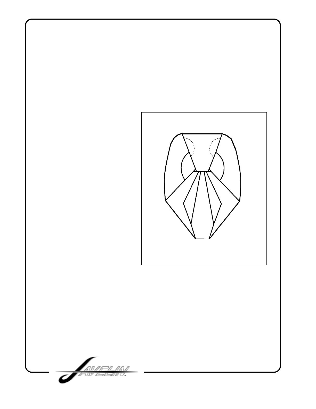
13. Close the top flap and
secure it with the ripcord pin.
(Be sure that your temporary
pin is accounted for at this
time!)
14. Using the packing paddle
push the fanned out pilot
chute fabric under the bottom
closure flap (ensure fabric is
over bridle and not under it)
to leave a clean and tidy pack
job. Seal the reserve
container and log the work
done on the packing data
card and in your rigger's
logbook. Place the
completed data card in the
pocket provided on the
underside of the reserve top
flap cover . Secure the top flap
cover over the top flap by
inserting the tongue on each
side under the top flap and
insert the bottom of the top
flap into the protector pocket
(FIG. 10).
FIG. 10
15. COUNT YOUR TOOLS!
30
Page 31

JAVELIN RESERVE STATIC LINE
CAUTION
Although the
Reserve Static Line
is considered to be very
dependable, it is only a backup and should never be relied
upon entirely for activ ation of the reserve. In the e vent of a
breakaway or cutawa y, the jumper should follo w through by
pulling the reserve ripcord handle as if there were no
Reserve Static Line.
It must also be understood that the
Reserve Static Line
will
NOT operate in the e vent of a TO T AL malfunction of the main.
In October 1990, Sun Path adopted the Reserve Static Line (RSL) as a standard
feature on all JAVELIN harness/container systems. The RSL is a simple, inexpensive
but effective way of assuring that the reserve ripcord will be pulled immediately after
disconnecting from the main canopy. The RSL is also designed not to interfere
whatsoever with manual activation of the reserve.
For the very few cases where immediate reserve activation may not be desired, the
JAVELIN RSL features a quick-release which can be used to disconnect the RSL.
This quick-release consists of a snap-shackle which is normally attached to a small
ring on the inboard side of the left main riser. Release of the snap-shackle is
accomplished by a quick tug on the red ribbon attached to the release ring.
Some jumpers feel that the RSL should not be connected during Canopy Relative
Work, preferring to disconnect from the main and then fall free of a "wrap" before
deploying the reserve. Also, if winds are high, the jumper may disconnect the main
canopy after landing to avoid being dragged. In this case the quick-release can be
used prior to landing to prevent an unnecessary activation of the reserve.
4439 Skydive Lane Zephyrhills, FL 33540 USA • Phone (813) 782-9242 Fax (813) 788-3057 • Web Site www.sunpath.com
31
Page 32
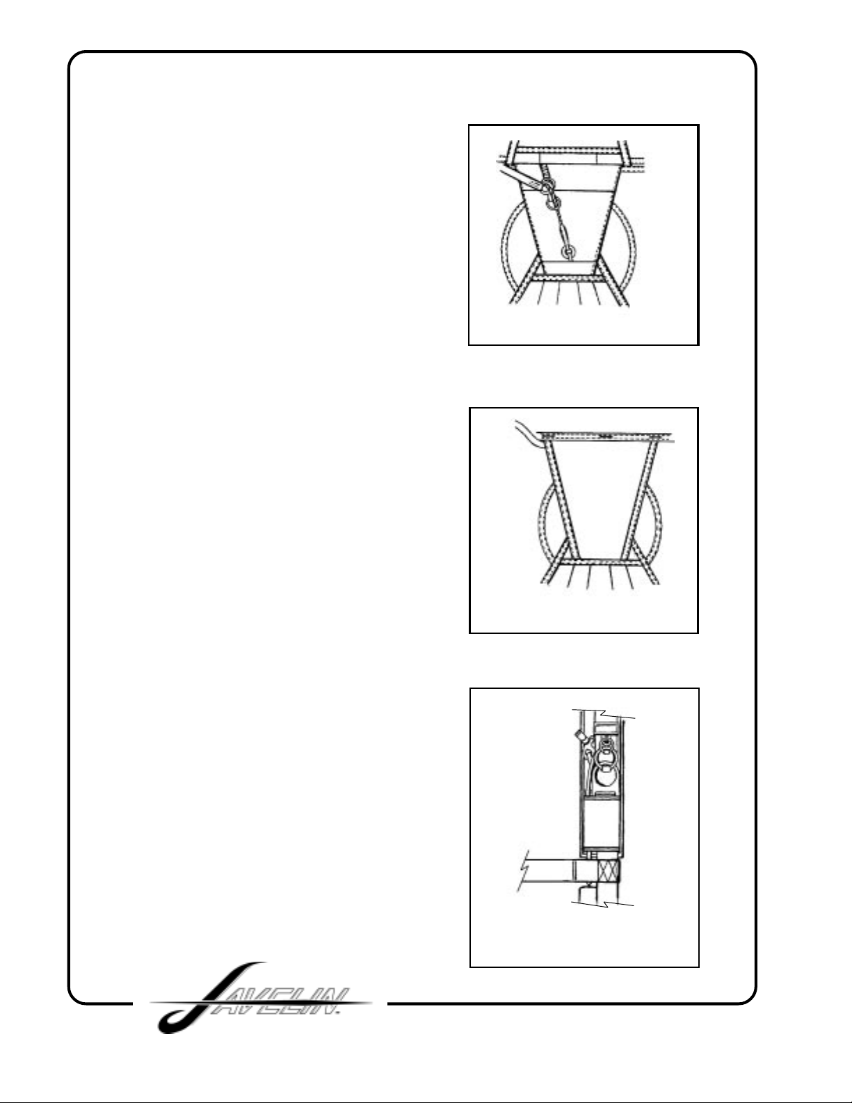
ASSEMBLING THE RSL
There are two small rings mounted
on the reserve top flap near the end of
the reserve ripcord housing. After
installing the reserve ripcord in the
housing, the cable must be passed
through the ring nearest the housing.
It is then passed through the ring on
the end of the Reserve Static Line,
then through the ring nearest the
grommet in the reserve top flap (FIG.
1).
It is important to assemble the cable
with the rings in this exact order, the
ring nearest the grommet keeps the
cable in line with the pin during
activation and the ring nearest the
housing prevents the ring of the RSL
from being caught on the end of the
housing.
FIG. 1
FIG. 1
After the reserve container is closed
and the rigger's seal is installed, the
Reserve Static Line must be routed out
from under the reserve pin cover at the
upper left as shown in (FIG. 2).
The velcro of the RSL should be mated
to the velcro on the left reserve riser to
bring the RSL over the shoulder.
Then the snap-shackle can be
connected to the small ring behind the
inboard side of the left main riser
(FIG. 3).
There should be enough slack in the
RSL so that the main riser can be
pulled in any direction without putting
any tension on the reserve riser. Any
slack in the RSL near the reserve pin
cover can be tuc ked under the reserve
top flap. (This may vary with the size
of the rig.)
FIG. 2
FIG. 2
32
FIG. 3
Page 33
THE 3-RING RELEASE CABLE LENGTHS
After the cables have been installed in the housings of y our Javelin harness/container
there should be 5 1/2” of excess cable on the user’s left-hand and right-hand side.
These measurements are based on extensive testing and should not be altered in
anyway to change the correct operation of the RSL.
THE 3-RING RELEASE SYSTEM
The 3-Ring Release System was invented by the Relative Workshop in 1976. It
was the first practical release that allowed parachutists to jettison their main canopies
in one motion by simply pulling a single handle. Not only is the 3-Ring easier to
operate than previous canopy release systems, it is also more reliable. Failures of
a properly built and assembled 3-Ring system are virtually unknown. Once the
main is jettisoned, the only things left on the harness are two smooth rings that
cannot snag a deploying reserve. Some other popular release systems can-and
have-interfered with the deploying reserve.
GETTING TO KNOW THE 3-RING
Knowing how the 3-Ring release works will help you assemble and inspect it properly.
Begin by peeling the release handle from the Velcro on the harness. Peeling, rather
than pulling, makes it easier to separate the handle from the webbing. Look behind
the risers near the harness and obser ve the movement of the yellow cable as you
pull the handle. When the cable clears the white loop, the release is disengaged.
Now slowly pull one of the risers off the harness. As you pull, you'll notice that the
white loop gets pulled through the grommet by the action of the smallest ring. Each
ring forms a lever with a ten-to-one mechanical adv antage as it passes through the
other. A force of 1,000 lb. on the large harness ring exerts a force of only ten
pounds on the white loop. (Opening shock usually totals about 1,000 lb., or 500 lb.
on each riser).
NOTE:
Sun Path does not recommend the use of “Reverse Riser s” on Javelin Harness
and Containers.
4439 Skydive Lane Zephyrhills, FL 33540 USA • Phone (813) 782-9242 Fax (813) 788-3057 • Web Site www.sunpath.com
33
Page 34
Because of the mechanical advantage provided by the 3-Ring design, only a force of
approximately a pound on the top ring keeps the release together. That's why it's
important to keep foreign matter like bits of grass and stic ks out of the 3-Ring assembly .
A small stick in the white loop could prevent a riser from
releasing. It is also important to understand one of the properties of the nylon
components of the system. When nylon stays in the same position for a long time, it
begins to conform to that position, or take a "set". If the 3-Ring release system stays
assembled for too long, the nylon can become so stiff that the low drag from a
malfunction (such as a streamer) won't pull the riser off the ring. The 3-Ring release
system must be disassembled, flexed and inspected every month. Procedures for
this are listed in the maintenance chapter of the manual.
ASSEMBLY
Before assembling the 3-Ring release, mak e sure the
risers aren't twisted or reversed. Lay the JAVELIN
face down, as you would to pack it.
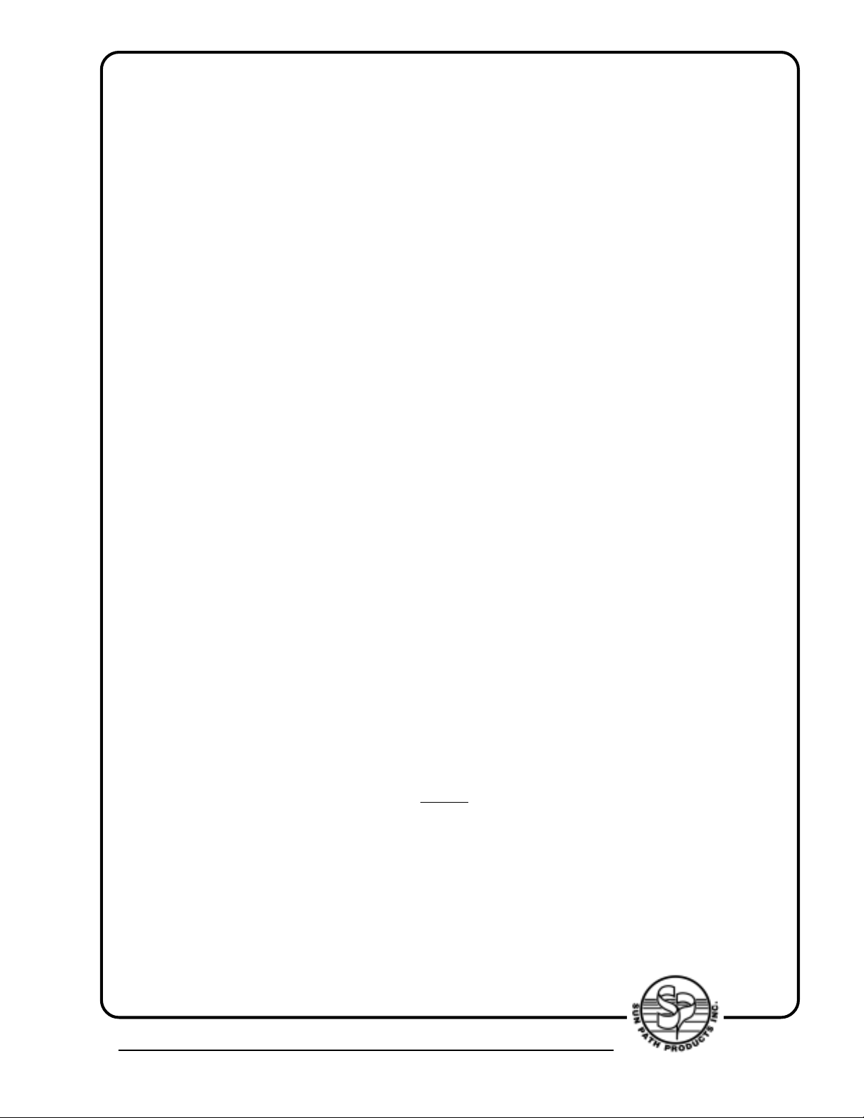
1. Thread the cable into its housing and stick the cut
away/release handle to the harness. The handle
should be positioned as close to the ends of the
housings as possible so that no cable is exposed.
2. With the rings of the riser facing toward the floor,
pass the ring on the end of the riser through the large
harness ring from above. Fold it back toward the
canopy and risers (FIG 1).
3. Thread the smallest ring through the middle ring
in the same way, but make sure it doesn't pass through
the large ring (FIG. 2).
FIG. 1
FIG. 2
34
Page 35
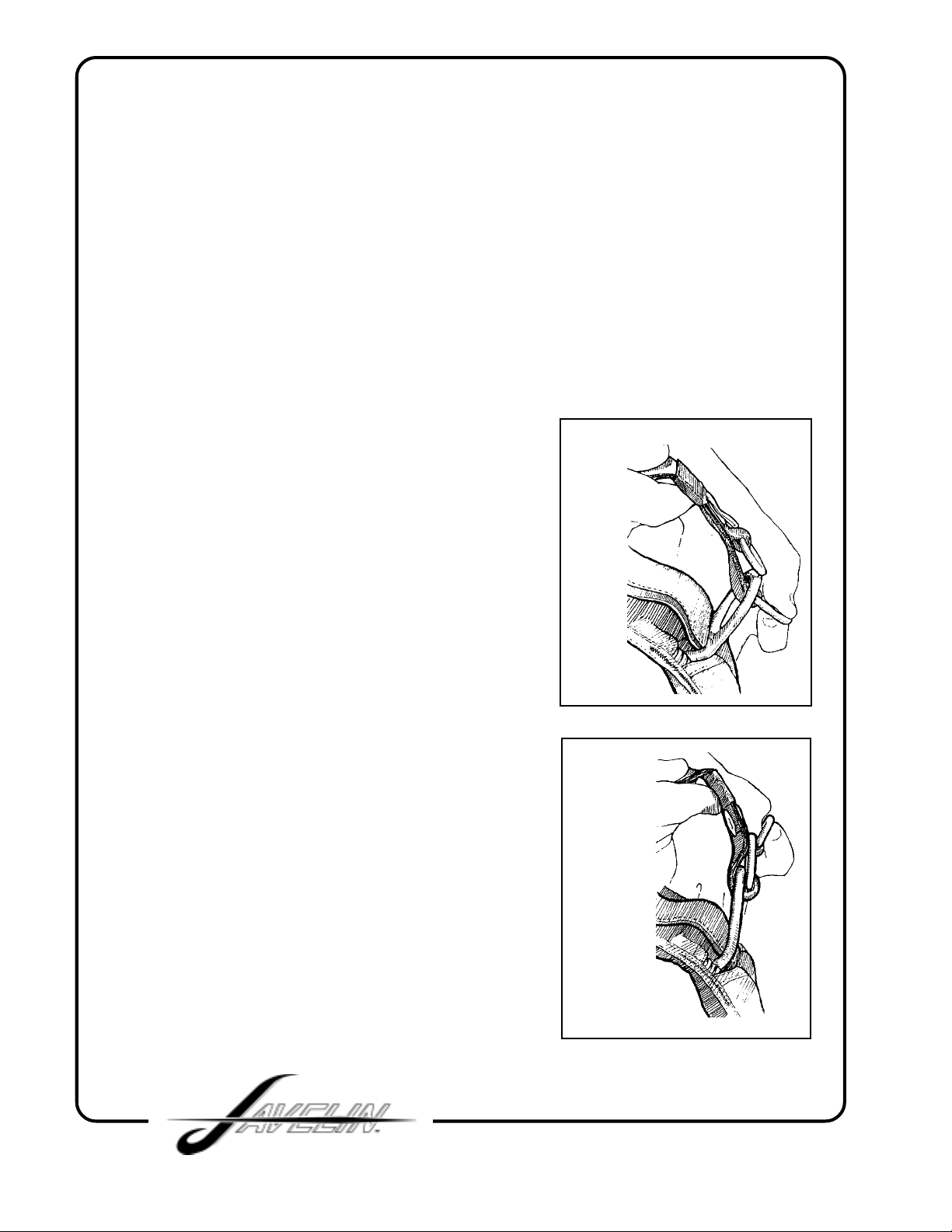
4. Bring the white loop over the small
ring only and then through the riser
grommet so it pokes out the back of
the riser (FIG 3).
5. Continue threading the white loop
through the grommet on the end of
the cable housing. The flat side of
the cable housing grommet should
be against the riser (FIG 4).
FIG. 3
FIG. 4
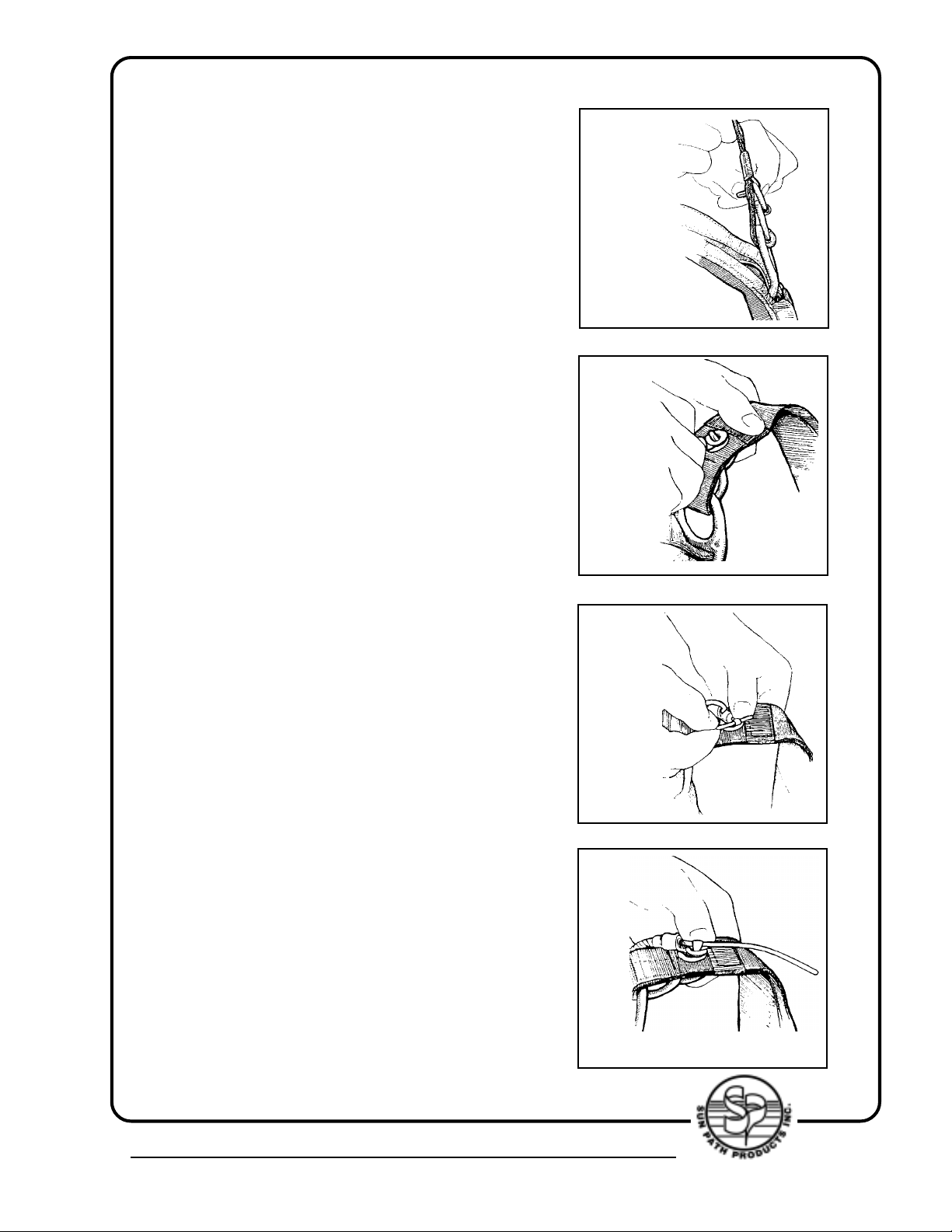
6. Thread the yellow cable through
the white loop, making sure the loop
isn't twisted (FIG 5).
7. Be careful with the cable so you don't
bend it too sharply or kink it (FIG 6).
FIG. 5
FIG. 6
4439 Skydive Lane Zephyrhills, FL 33540 USA • Phone (813) 782-9242 Fax (813) 788-3057 • Web Site www.sunpath.com
35
Page 36
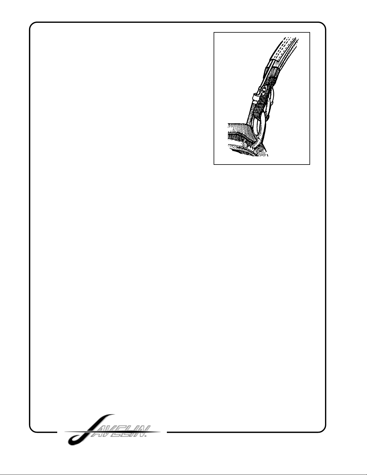
8. Insert the free end in the channel on the
back of the riser (FIG. 7).
Repeat the above steps with the other riser.
FIG. 7
REQUIRED PERIODIC MAINTENANCE FOR THE 3-RING
The Booth 3-Ring Release System has been in use for many years with e xcellent results .
Although the system is as durable as the rest of the harness/container assembly, it
requires periodic maintenance and inspection to ensure proper operation. Generally it is
NOT recommended that the risers be attached to the harness when new and "forgotten."
Like all skydiving gear, the 3-Ring Release should be carefully inspected and operated
on a regular basis. The procedures below should be done at least ever y month. This is
especially important if the rig has not been used for a month or more, such as during the
winter. Immediate inspection is required if it has been subjected to some abuse such as
a drag across the runway, a water landing or exposure to a lot of dust or sand.
1. Every month operate the 3-Ring release system on the ground. Extract the cable
completely from the housings and disconnect the risers.
2. While the system is disassembled, closely inspect it f or wear . Check the white locking
loops (the ones that pass over the smallest ring and through the grommet) to be sure
they are not frayed.
3. Check the Velcro on the breakaway handle and main lift web to be sure it is clean and
adequately holds the handle.
4. Check the cable ends for a smooth finish. The ends are finished at the f actory to have
a smooth, tapered surface. This prevents the cable from hanging up in the loop. Check
the cable ends and consult a rigger or the manufacturer if a burr or "hook" is present.
5. Check the stitching, including that which holds the large rings to the harness.
6. Pull downward on the housings. They shouldn't move downw ards more than 1/2 inch.
36
Page 37
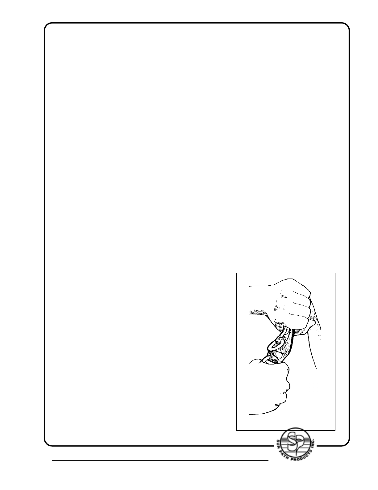
7. Take each riser and vigorously twist and flex the webbing near where it passes through
each ring. The idea is to remov e any set or deformation of the webbing. Do the same thing
to the white loop. (FIG. 1)
8. Check the housings for dents or other obstructions. Use the cable to do this.
9. Clean and lubricate the release cable with a light oil such as a "3-in-1" brand. Put a f ew
drops on a paper towel and firmly wipe the cable a few times. A thin, invisible film should
remain--too much will attract grit and dirt, or the oil could become tacky in cold weather.
Too much oil will require more force to extract the cable during a breakaway.
10. Inspect the fittings at the end of each housing. If one of these fittings were to come off
the housing, a riser might release prematurely.
11. If any wear is found, consult a rigger or the manufacturer before using the JAVELIN.
12. Reassemble the system. Double check it. Make sure the risers aren't reversed.
It's important to maintain the system even more frequently in humid, muddy or freezing
conditions. If the JAVELIN becomes immersed in mud or muddy water, clean the 3-Ring
release system with a mild solution of soap and water. Any rusted components must be
replaced.
BEFORE USING THE JAVELIN
1. Read and understand this manual and be qualified by proper instruction for
sport parachuting activities.
2. Check both 3-Ring releases to see that they
are correctly assembled and check to see the
release handle is securely attached (V elcro) to the
main lift web.
3. Check the main container closure for correct
pin position and correct routing of the bridle. The
little velcro tab on the bridle must be mated to the
one on the top flap.
4. Check the reserve container for correct pin
closure and routing of the ripcord. Be sure the
reserve ripcord handle is well seated in its velcro
pocket.
5. The main pilot chute must be protected by its
pouch, but the handle must be easily accessible
and or visible.
FIG 1.
4439 Skydive Lane Zephyrhills, FL 33540 USA • Phone (813) 782-9242 Fax (813) 788-3057 • Web Site www.sunpath.com
37
Page 38
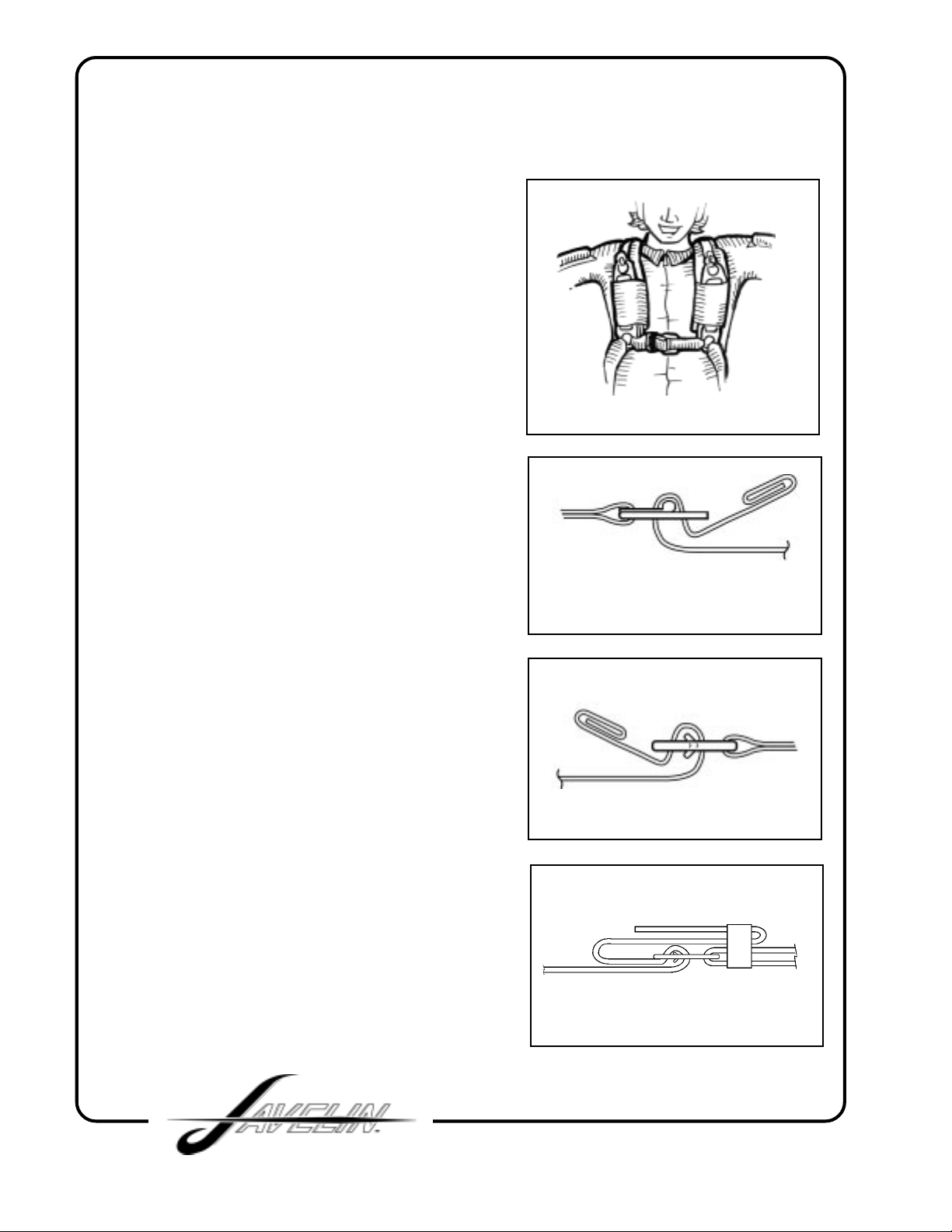
DONNING THE JA VELIN
When lifting the JAVELIN, grasp the main lift
web between the large harness ring and the
chest strap. Put the rig on as you would a
jacket, settling the yo ke across the shoulders.
Step through the leg straps, being sure they
aren't twisted, then thread the chest strap
through its friction adapter (adjustor) and
tighten it to where it is comfortably snug. Be
sure it has NOT been threaded through the
reserve ripcord handle.
Tighten the leg straps until they are
comfortably snug and stick the free end of
the strap down into the leg pad or in an elastic
keeper. It is important to secure these free
ends; a loose free end can easily be mistak en
for a deployment handle.
FIG 1
RING HARNESS ADJUSTMENT
If your Javelin is equipped with a ringed
harness, to insure a proper and comfortable
fit, it is very important that you tighten the
chest strap first. By first tightening the chest
strap very snugly, this will allow full arm and
shoulder movement. Next tighten the leg
strags until they are comfor tably snug. (FIG.
1)
Be sure all the friction adapters are correctly
threaded. The webbing must pass under the
adapter (next to the jumper's body) and come
up through the frame above the mov able bar,
then back around the moveable bar and
under the end of the frame. If the webbing is
routed in any way other than what is shown
in
(FIG. 2) or (FIG. 3).
(1” chest strap) F old the free end of the chest
strap back onto the short side and stow the
excess in the 1” elastic keeper (FIG. 4).
IT MAY NOT HOLD!
FIG 2 (LEG STRAP)
FIG 3 ( 2” CHEST STRAP)
FIG 4 ( 1” CHEST STRAP)
38
Page 39

This section is not a full course of instruction on how to deal with emergencies. It is meant
only to explain the function of the JAVELIN harness/container system. Learning the proper
procedures and deciding when, or if, to use them is the responsibility of the jumper , who must
be thoroughly trained by an experienced and qualified instructor before attempting to make a
parachute jump.
MAIN DEPLOYMENT
BEFORE JUMPING
The pouch for the main pilot chute is located at the right hip on the outside of the right leg pad
or on the bottom of the main container. When the pilot chute is packed correctly, the handle
should be visible and easy to grasp at the top of the pouch. (It is very impor tant that the
jumper familiarize himself with all handles and activation de vices on his rig bef ore jumping).
Practice locating the handle, grasping it and e xtracting the pilot chute. Then go through the
same procedure without looking at it. This should be done under the supervision of an instructor.
The pilot chute pouch location on some JA VELIN's will not allo w the handle to be visible . i.e.
JAVELIN's fitted with B.O.C . (Bottom of Container) or pull out.
IN THE AIR
In a flat and stable position face-to-earth, grab the pilot chute handle and in one motion,
extract the pilot chute from the pouch and vigorously throw it STRAIGHT OUT to the side,
placing it in clean air. If you are in the air with other jumpers, the wave-off should be done
before extracting the pilot chute . W aving off with the pilot chute in hand may cause a premature
opening of the container.
RESERVE DEPLOYMENT
PARTIAL MALFUNCTION
A partial malfunction occurs when the canopy has come out of the container, but has not
opened properly. Most jumpers are now trained to jettison (disconnect) the main canopy
before activating the reserve if the partial malfunction is serious enough to warrant emergency
procedures. Disconnecting from the main is called a "breakawa y" or "cutawa y" and it is done
to prevent the entanglement of the reserve with the main.
PROCEDURE
Look down and locate both the cutawa y/release handle (on right main lift web) and the reserve
ripcord handle (on left main lift web). Gr ab the cutaw ay/release handle and peel it a wa y from
its velcro mount. Pull it vigorously downw ard and outward as f ar as the arm will reach. Throw
it away and then grasp the reserve ripcord handle. Pull it vigorously downward and outward
as far as the arm will reach. It must be emphasized that it is the jumper’s responsibility to
decide whether any emergency procedure is appropriate and to decide whether he has enough
time or altitude to perform it. Obviously if the jumper decides that he is too low to perform a
breakaway, he should simply active the reserve.
4439 Skydive Lane Zephyrhills, FL 33540 USA • Phone (813) 782-9242 Fax (813) 788-3057 • Web Site www.sunpath.com
39
Page 40

TOTAL MALFUNCTION
A total malfunction occurs when the main canopy is still in the container after an attempt
has been made to activate it. This may occur if the pilot chute cannot be extracted from
its pouch, or if the pilot chute is inflated but cannot open the container. It is generally
considered best when presented with a total malfunction to simply pull the reserve
ripcord without breaking away from the main canopy. A total malfunction always leaves
the jumper falling at high speed and breaking away from a canopy that is still in the
container may waste precious time and altitude.
PROCEDURE
Look at the reserve ripcord handle (the metal handle or soft handle just below the chest
strap on the left main lift web), grasp it with both hands and pull it downward and outw ard
with all your strength and as far as you can reach. It is usually considered best to be in
a stable position somewhat head-high when deplo ying any canopy , b ut if time and altitude
are running out, body position is not as important as getting the canopy out!
DEAR JAVELIN OWNER,
It is the goal of SUN P ATH PRODUCTS, INCORPORATED to produce and sell the best sport
parachute equipment that can be manufactured with toda y's materials and technology . In this
effort, it is important that we obtain all the feedback from our customers that we can. We
would like for you to share with us any observations, problems, suggestions, etc., that you
may hav e. Our primary concern is of course the SAFETY and DEPENDABILITY of the JA VELIN
harness/container system. After that,
We thank you for your choice of the JAVELIN and we hope for your continued confidence in
SUN PATH PRODUCTS INC.
BLUE SKIES and SAFE DIVES,
SUN PATH PRODUCTS, INC.
your satisfaction comes first.
40
Page 41
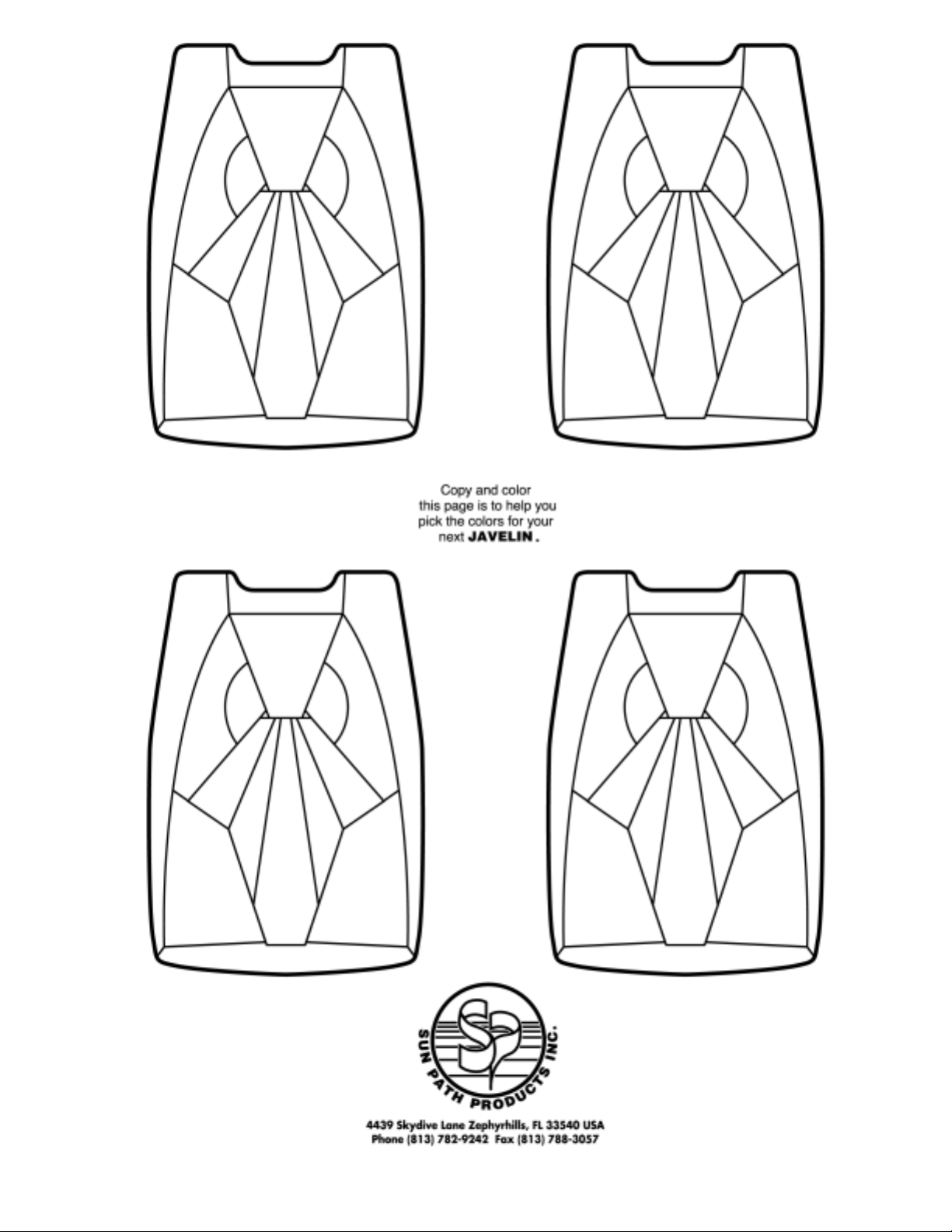
Check out the
on-line color selector at:
www.sunpath.com
4439 Skydive Lane Zephyrhills, FL 33540 USA • Phone (813) 782-9242 Fax (813) 788-3057 • Web Site www.sunpath.com
www.sunpath.com
41
Page 42

Appendix A: Maintenance and Repairs
Applicable to all Javelin and Javelin Odyssey harness/container systems, sport and
student.
Your Javelin/Javelin Odyssey harness container system is built with the latest
technology and most up to date manufacturing methods.
QUALIFIED PERSONELL:
It is strongly recommended that all major repairs to Javelin/Javelin Odyssey harnesses
and container systems be made at the manufacturers’ facility in Zephyrhills, Florida.
AUTHORIZATION:
Javelin/Javelin Odyssey harness/container systems are certified under TSO c23d. The
TSO label is located under the reserve pin cover flap or inside the pocket on the yoke if
the rig has a clear reserve pin cover. If this label is not present or has been removed
NOT PACK THE RIG. Removal of the TSO label voids the TSO and all
certification approvals.
IF THERE ARE ANY VISIBLE SIGNS OF WEAR OR DAMAGE, HAVE YOUR
RIG THOROUGHLY INSPECTED BY A CERTIFIED PARACHUTE RIGGER
OR OUR MANUFACTUREING FACILITY IN ZEPHYRHILLS, FLORIDA
BEFORE NEXT USE.
LIMITS AND GUIDELINES FOR DAMAGE:
Limits and guidelines for webbing are applicable to all sections of the harness. To
include reserve risers, main lift web, lateral/diagonal and leg straps.
At every repack cycle, the entire harness/container system should be thoroughly
inspected. Completion of this inspection and annotation of an A/I/P or A/I/R on the
packing data card implies that the certifying party has inspected and deemed the harness,
container and all applicable components to be airworthy and ready for use.
A visual inspection of the harness webbing and hardware should be conducted before
each use to determine whether or not it is showing signs of abrasion, fraying, nicks,
unusual wear and tear or any other visible damage to any part of the webbing and or
hardware damage that will degrade its strength. Refer to the following grading list as a
guideline for determining webbing wear.
DO
Page 43
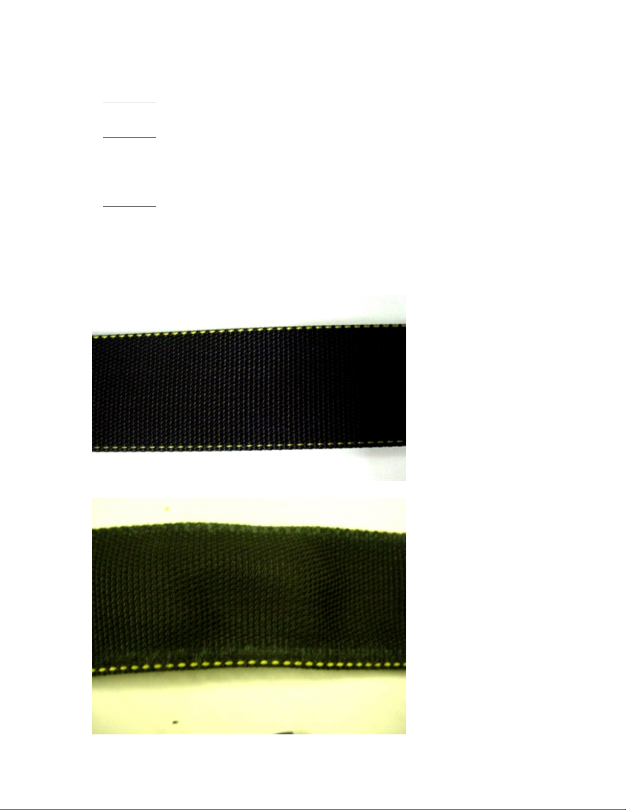
Grade 1 Like new, does not need replacement. See Fig. 1
■
Grade 2 Minor Hook and Loop type abrasion.
■
Minor wear due to normal use. Replacement optional, make note
to inspect specific area on every repack cycle. See Fig. 2
Grade 3 Any damage to selvedge edges of harness
■
webbing. Broken or missing harness stitching. Mandatory
replacement or repair. See Fig. 3
Figure 1 Grade 1
Figure 2 Grade 2
Page 44
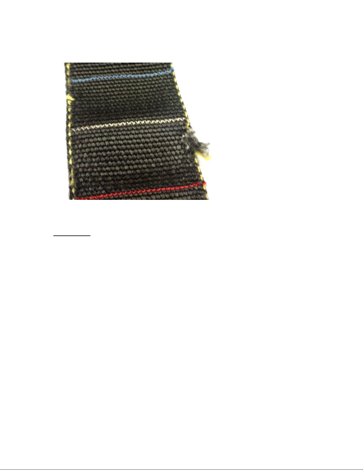
Figure 3 Grade 3
STORAGE:
Textiles and other materials used in the manufacture of parachute equipment to include
harness/container systems are sensitive to the following environmental elements.
Water/humidity
Salt water
Ultraviolet rays (Sunlight)
All petroleum based products (oil, grease)
Rodents, pests
Smoke
Excessive heat
Chlorine (bleach)
Acid
While the parachute equipment is not in use it is recommended to store the gear in a
proper gear bag and in a room where the temperature and humidity is maintained.
 Loading...