

Page 1

Sun Server X3-2
(formerly Sun Fire X4170 M3)
Installation Guide
Part No.: E22359-14
April 2014
Page 2

Copyright ©2013, 2014,Oracle and/orits affiliates.All rightsreserved.
This softwareand related documentationare provided undera licenseagreement containingrestrictions on use and disclosure and areprotected by
intellectual propertylaws. Exceptas expressly permittedin yourlicense agreementor allowedby law,you maynot use,copy, reproduce, translate,
broadcast, modify, license,transmit, distribute,exhibit, perform,publish, ordisplay anypart, inany form,or byany means.Reverse engineering,
disassembly, or decompilation of this software, unlessrequired by law for interoperability, is prohibited.
The informationcontained hereinis subjectto changewithout noticeand isnot warrantedto beerror-free.If youfind anyerrors, please report them to us
in writing.
If thisis softwareor related softwaredocumentation thatis delivered tothe U.S.Government oranyone licensingit onbehalf ofthe U.S.Government, the
following noticeis applicable:
U.S. GOVERNMENTEND USERS.Oracle programs,including anyoperating system,integrated software, anyprograms installedon thehardware,
and/or documentation,delivered toU.S. Governmentend usersare "commercial computer software" pursuantto theapplicable FederalAcquisition
Regulation andagency-specific supplementalregulations. Assuch, use,duplication, disclosure, modification,and adaptationof theprograms, including
any operatingsystem, integratedsoftware, anyprograms installed on the hardware,and/or documentation,shall besubject tolicense termsand license
restrictions applicableto theprograms. No other rights are granted to the U.S. Government.
This software or hardware is developed for general use ina varietyof informationmanagement applications. It is not developed orintended foruse inany
inherently dangerous applications,including applicationswhich maycreate arisk ofpersonal injury. Ifyou usethis softwareor hardware indangerous
applications, thenyou shallbe responsibleto takeall appropriate fail-safe,backup, redundancy, andother measuresto ensure itssafe use.Oracle
Corporation andits affiliatesdisclaim anyliability forany damagescaused byuse ofthis software orhardware in dangerous applications.
Oracle andJava areregistered trademarks of Oracle and/or its affiliates.Other namesmay betrademarks oftheir respective owners.
Intel andIntel Xeonare trademarksor registered trademarksof IntelCorporation. AllSPARC trademarks areused underlicense andare trademarksor
registered trademarks of SPARCInternational, Inc. AMD, Opteron, theAMD logo,and theAMD Opteron logo are trademarksor registered trademarksof
Advanced MicroDevices. UNIXis aregistered trademark of The Open Group.
This software or hardware and documentation may provide access to or information on content, products, and services from third parties. Oracle
Corporation and its affiliates are not responsible for and expressly disclaim all warranties of any kind with respect to third-party content, products, and
services. Oracle Corporation and its affiliates will not be responsible for any loss, costs, or damages incurred due to your access to or use of third-party
content, products, or services.
Copyright ©2013, 2014,Oracle et/ouses affiliés.Tous droits réservés.
Ce logicielet ladocumentation quil’accompagne sontprotégés parles loissur lapropriété intellectuelle. Ils sont concédés sous licence et soumis à des
restrictions d’utilisationet dedivulgation. Saufdisposition devotre contrat de licence ou de la loi, vous ne pouvez pas copier, reproduire, traduire,
diffuser, modifier, breveter, transmettre,distribuer, exposer, exécuter,publier ouafficher le logiciel, même partiellement, sous quelque forme et par
quelque procédéque cesoit. Parailleurs, ilest interdit deprocéder àtoute ingénierieinverse dulogiciel, dele désassemblerou dele décompiler, excepté à
des finsd’interopérabilité avecdes logicielstiers outel queprescrit par la loi.
Les informationsfournies dansce documentsont susceptiblesde modificationsans préavis.Par ailleurs,Oracle Corporationne garantitpas qu’elles
soient exemptesd’erreurs etvous invite,le caséchéant, àlui enfaire part par écrit.
Si celogiciel, oula documentationqui l’accompagne,est concédésous licenceau Gouvernementdes Etats-Unis,ou àtoute entitéqui délivrela licencede
ce logicielou l’utilisepour lecompte duGouvernement desEtats-Unis, lanotice suivantes’applique:
U.S. GOVERNMENTEND USERS.Oracle programs,including anyoperating system,integrated software, anyprograms installedon thehardware,
and/or documentation,delivered toU.S. Governmentend usersare "commercial computer software" pursuantto theapplicable FederalAcquisition
Regulation andagency-specific supplementalregulations. Assuch, use,duplication, disclosure, modification,and adaptationof theprograms, including
any operatingsystem, integratedsoftware, anyprograms installed on the hardware,and/or documentation,shall besubject tolicense termsand license
restrictions applicableto theprograms. No other rights are granted to the U.S. Government.
Ce logicielou matériela étédéveloppé pourun usagegénéral dansle cadred’applications degestion desinformations. Celogiciel oumatériel n’estpas
conçu nin’est destinéà êtreutilisé dansdes applicationsà risque,notamment dansdes applicationspouvant causerdes dommagescorporels. Si vous
utilisez celogiciel oumatériel dansle cadred’applications dangereuses, ilest devotre responsabilité deprendre toutes les mesures de secours, de
sauvegarde, deredondance et autres mesures nécessaires à son utilisation dans des conditions optimales de sécurité. Oracle Corporation et ses affiliés
déclinent touteresponsabilité quantaux dommagescausés parl’utilisation dece logicielou matérielpour cetype d’applications.
Oracle etJava sontdes marquesdéposées d’OracleCorporation et/oude sesaffiliés.Tout autre nommentionné peutcorrespondre à des marques
appartenant àd’autres propriétaires qu’Oracle.
Intel etIntel Xeonsont desmarques oudes marques déposéesd’Intel Corporation.Toutes les marques SPARC sont utilisées sous licence et sont des
marques oudes marques déposéesde SPARC International, Inc. AMD, Opteron, le logo AMD et le logo AMD Opteron sontdes marquesou desmarques
déposées d’AdvancedMicro Devices.UNIX estune marque déposéed’The OpenGroup.
Ce logicielou matérielet ladocumentation quil’accompagne peuventfournir desinformations oudes liensdonnant accèsà descontenus, desproduits et
des servicesémanant detiers. OracleCorporation etses affiliésdéclinent touteresponsabilité ou garantie expresse quant aux contenus, produits ou
services émanantde tiers.En aucuncas, OracleCorporation etses affiliésne sauraientêtre tenus pour responsables des pertes subies, des coûts
occasionnés oudes dommagescausés parl’accès àdes contenus,produits ouservices tiers,ou àleur utilisation.
Please
Recycle
Page 3

Contents
Using This Documentation ix
About the Installation Procedure 1
Installation Procedure Overview 2
About Server Features and Components 5
Server Components 6
Front Panel Status Indicators, Connectors, and Drives 8
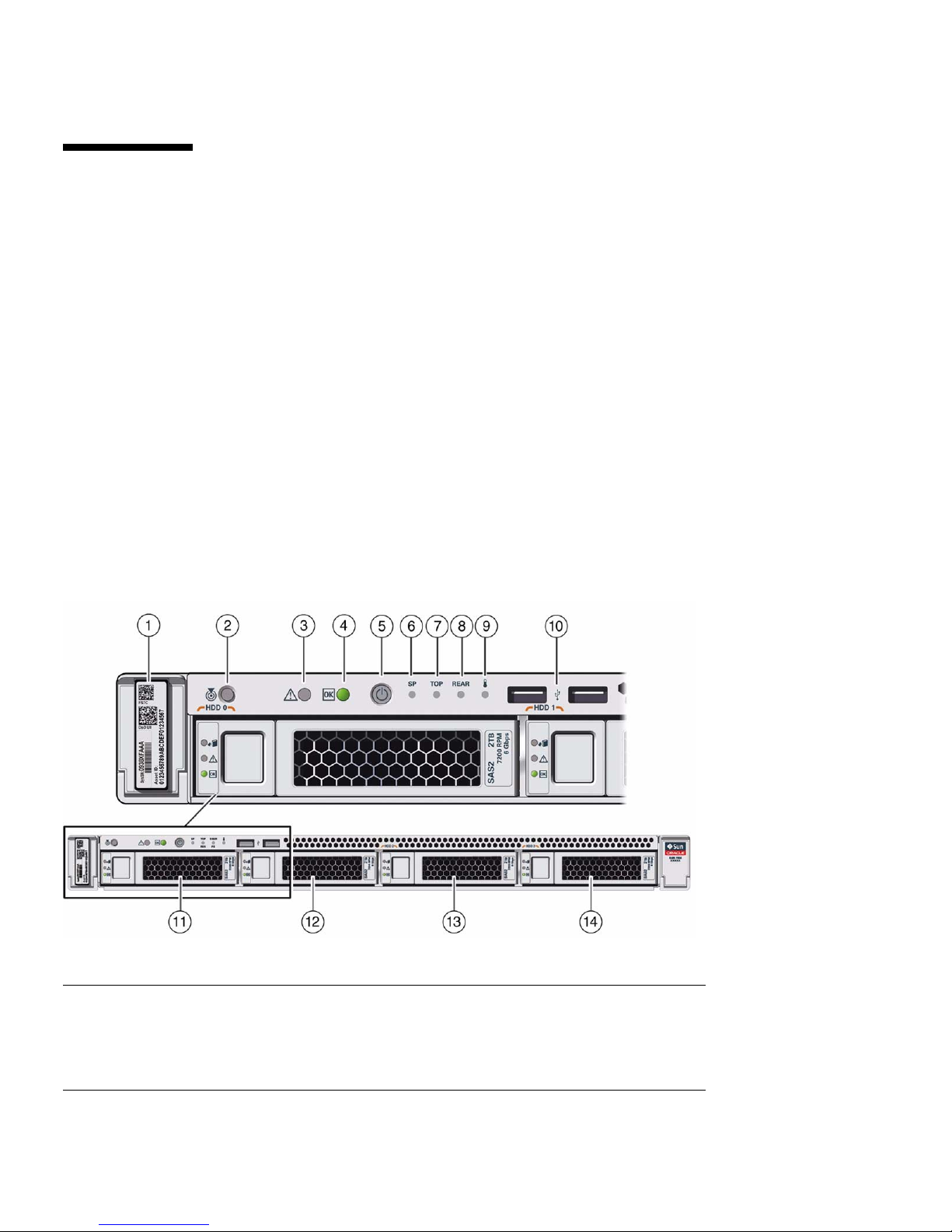
Front Panel With Four 3.5-inch Drives 8
Front Panel With Eight 2.5-inch Drives 9
Front Panel With Four 2.5-inch Drives and SATA DVD Drive 11
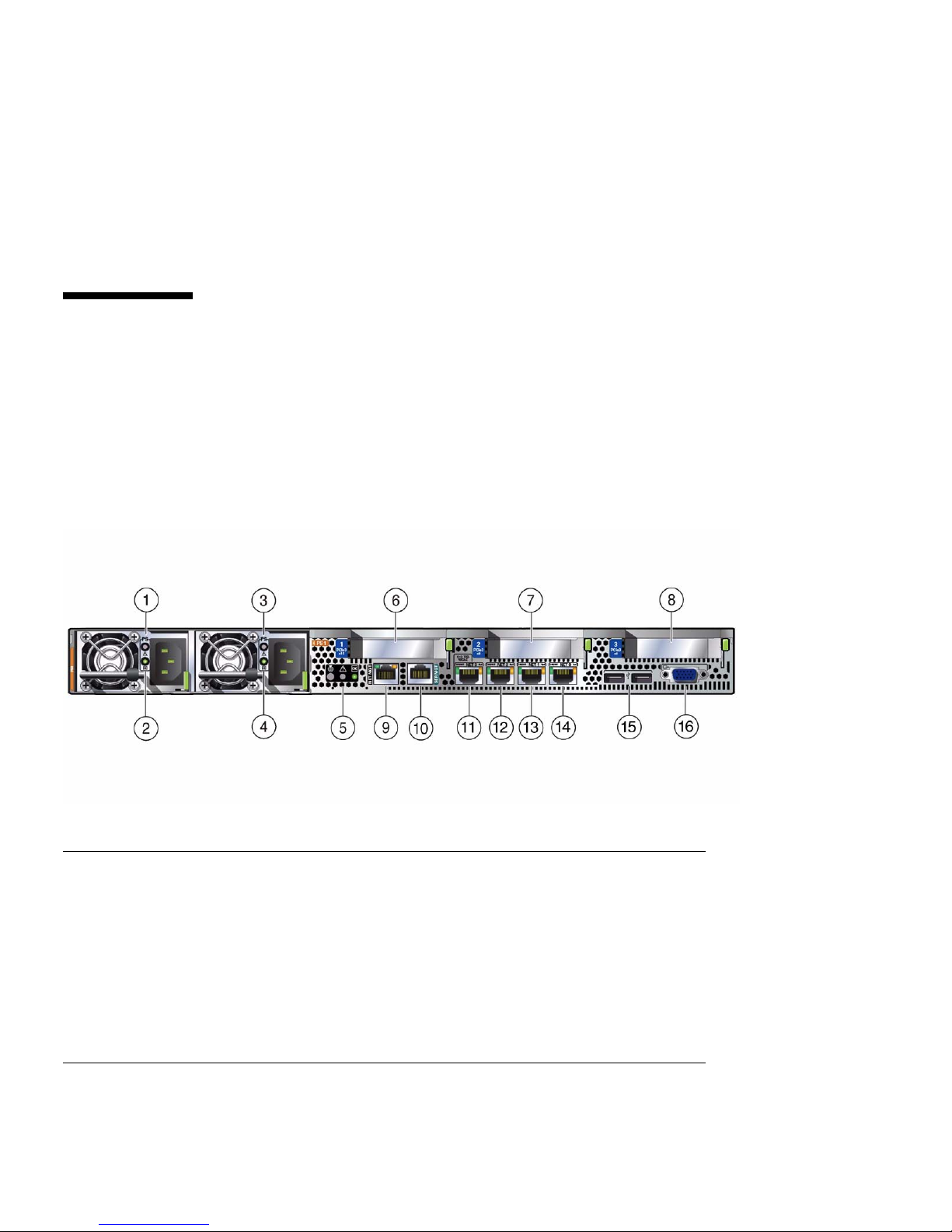
Back Panel Status Indicators, Connectors, and PCIe Slots 12
Server Management Software Overview 13
Oracle System Assistant 13
Oracle ILOM Overview 14
UEFI BIOS Overview 14
Boot Mode Selection 15
Legacy BIOS Boot Mode 15
UEFI BIOS Boot Mode 15
Preparing for Server Installation 17
Shipping Inventory 17
Tools and Equipment Needed for Installation 18
iii
Page 4

ESD and Safety Precautions 18
Optional Component Installation 19
Installing the Server Into a Rack 21
Installation Prerequisites 22
Rack Requirements 22
Safety Precautions When Rackmounting the Server 23
Rackmount Kit Contents 24
▼ Stabilize the Rack for Installation 25
▼ Install Mounting Brackets 26
▼ Mark the Rackmount Location 28
▼ Attach Tool-less Slide-Rail Assemblies 29
▼ Install the Server Into the Slide-Rail Assemblies 32
▼ Install the Second-Generation Cable Management Arm 35
▼ Remove the Second-Generation Cable Management Arm 46
▼ Install the First-Generation Cable Management Arm 50
Cabling the Server 57
Rear Cable Connections and Ports 57
Ethernet Ports 59
Attaching Data Cables and Power Cords to the Server 60
▼ Connect the Data Cables 60
▼ Connect the Power Cords 61
Connecting to Oracle ILOM 63
Oracle ILOM Hardware and Interfaces 64
Network Defaults 64
Logging In to Oracle ILOM Using a Local Serial Connection 65
▼ Log In to Oracle ILOM Using a Local Serial Connection 66
Logging In to Oracle ILOM Using a Remote Ethernet Connection 66
iv Sun Server X3-2 Installation Guide • April 2014
Page 5

Determining the IP Address of the Server SP 67
▼ Log In to Oracle ILOM Remotely Using the Web Interface 67
▼ Log In to Oracle ILOM Remotely Using the Command-Line
Interface 69
▼ View or Modify an SP IPv4 Address 70
▼ View or Modify an SP IPv6 Address 73
Accessing the Host Console Through Oracle ILOM 75
▼ Set Mouse Mode 76
▼ Connect to the Host Console Using the Oracle ILOM Web Interface
76
▼ Connect to the Host Serial Console Using the Oracle ILOM Command-
Line Interface 79
Troubleshooting the Service Processor Connection 79
▼ Reset the Service Processor Using Oracle ILOM 80
▼ Reset the Service Processor From the Server Back Panel 80
▼ Recover Root Account Password 81
Setting Up Software and Firmware Using Oracle System Assistant 83
▼ Set Up Software and Firmware 84
Setting Up an Operating System and Drivers 86
Configuring Server Drives for OS Installation 89
RAID Configuration Tools 89
RAID Configuration Requirements 90
Configuring Storage Drives Into RAID Volumes Using Oracle System
Assistant 92
▼ Configure RAID on Storage Drives Using a Sun Storage 6 Gb SAS PCIe
Internal HBA 93
▼ Configure RAID on Storage Drives Using a Sun Storage 6 Gb SAS PCIe
RAID Internal HBA 101
Configuring RAID Using the BIOS RAID Configuration Utilities 110
Configuring RAID With the Sun Storage 6 Gb SAS PCIe Internal HBA 110
Contents v
Page 6

▼ Configure RAID in UEFI Boot Mode With the Sun Storage 6 Gb
SAS PCIe Internal HBA 111
▼ Configure RAID in Legacy BIOS Boot Mode With the Sun Storage
6 Gb SAS PCIe Internal HBA 113
Configuring RAID in UEFI Boot Mode With the Sun Storage 6 Gb SAS PCIe
RAID Internal HBA 114
▼ Configure RAID in UEFI Boot Mode With the Sun Storage 6 Gb
SAS PCIe RAID Internal HBA 115
Configuring RAID in Legacy BIOS Boot Mode With the Sun Storage 6 Gb
PCIe RAID Internal HBA 123
▼ Create a RAID Volume in Legacy BIOS Boot Mode Using the BIOS
RAID Configuration Utilities 124
▼ Make a RAID Volume Bootable Using the LSI WebBIOS
Configuration Utility 124
Configuring the Preinstalled Oracle Solaris 11 Operating System 129
Preinstalled Operating System RAID Limitations 130
Operating System Options 130
Oracle Solaris Configuration Worksheet 131
▼ Configure the Preinstalled Oracle Solaris 11 Operating System 134
Oracle Solaris 11 Operating System Documentation 136
Configuring the Preinstalled Oracle Linux 6.x Operating System 137
Oracle Linux 6.x Configuration Worksheet 137
▼ Configure the Preinstalled Oracle Linux 6 Operating System 138
▼ Register and Update Your Linux Operating System 141
Oracle Linux Operating System Documentation 142
Configuring the Preinstalled Oracle VM 3.x Software 143
Preinstalled Oracle VM Server and Oracle VM Manager Compatibility
Requirements 144
Oracle VM Server Configuration Worksheet 144
▼ Configure the Preinstalled Oracle VM 145
vi Sun Server X3-2 Installation Guide • April 2014
Page 7

Oracle VM Documentation 149
Controlling System Power and Troubleshooting Installation Issues 151
Power Off the Server for Orderly Shutdown 152
▼ Use the Power Button for Orderly Shutdown 152
▼ Use the Oracle ILOM Command-Line Interface for Orderly
Shutdown 153
▼ Use the Oracle ILOM Web Interface for Orderly Shutdown 153
Power Off the Server for Immediate Shutdown 154
▼ Use the Power Button for Immediate Shutdown 154
▼ Use the Oracle ILOM Command-Line Interface for Immediate
Shutdown 155
▼ Use the Oracle ILOM Web Interface for Immediate Shutdown 155
Reset the Server 156
▼ Use the Oracle ILOM Command-Line Interface to Reset the Server
156
▼ Use the Oracle ILOM Web Interface to Reset the Server 156
Installation Troubleshooting 157
Technical Support Information Worksheet 159
Locating the System Serial Number 160
Getting Server Firmware and Software 161
Firmware and Software Updates 161
Firmware and Software Access Options 162
Software Releases 162
Getting Firmware and Software from MOS or PMR 164
▼ Download Firmware and Software Using My Oracle Support 164
Requesting Physical Media 165
Gathering Information for the Physical Media Request 165
▼ Request Physical Media (Online) 166
Contents vii
Page 8

▼ Request Physical Media (By Phone) 167
Installing Updates Using Other Methods 168
Index 169
viii Sun Server X3-2 Installation Guide • April 2014
Page 9

Using This Documentation
This installation guide contains hardware installation procedures and configuration
procedures for the Sun Server X3-2.
Note – The Sun Server X3-2 was formerly named the Sun Fire X4170 M3 server. This
former name might still appear in the software. The new product name does not
indicate any change in system features or functionality.
This document is written for technicians, system administrators, authorized service
providers, and users who have an understanding of server systems.
This section describes how to get the latest software and firmware, documentation
and feedback, and support and accessibility information.
■ “Getting the Latest Software and Firmware” on page ix
■ “About This Documentation” on page x
■ “Related Documentation” on page x
■ “Feedback” on page x
■ “Access to Oracle Support” on page xi
Getting the Latest Software and
Firmware
Firmware, drivers and other hardware-related software for each Oracle x86 server,
server module (blade), and blade chassis are updated periodically.
You can obtain the latest version in one of three ways:
ix
Page 10

■ Oracle System Assistant – This is a new factory-installed option for Oracle x86
servers. It has all the tools and drivers you need and is built into the server.
■ My Oracle Support: http://support.oracle.com
■ Physical media request
For more information, see “Getting Server Firmware and Software” on page 161.
About This Documentation
This documentation set is available in both PDF and HTML formats. The information
is presented in topic-based organization (similar to online help) and therefore does
not include chapters, appendices, or section numbering.
A PDF version that includes all information on a particular topic subject (such as
hardware installation or product notes) can be generated by clicking the PDF button
in the upper left corner of the HTML page.
Related Documentation
Documentation Link
All Oracle documentation http://www.oracle.com/documentation
Sun Server X3-2 http://www.oracle.com/pls/topic/lookup?ctx=
SunServerX3-2
Oracle Integrated Lights Out
Manager (ILOM) 3.1
Oracle Hardware
Management Pack 2.2
http://www.oracle.com/pls/topic/lookup?ctx=
ilom31
http://www.oracle.com/pls/topic/lookup?ctx=
ohmp
Feedback
You can provide feedback on this documentation at:
x Sun Server X3-2 Installation Guide • April 2014
Page 11

http://www.oracle.com/goto/docfeedback
Access to Oracle Support
Oracle customers have access to electronic support through My Oracle Support. For
information, visit http://www.oracle.com/pls/topic/lookup?ctx=acc&id=
info or visit http://www.oracle.com/pls/topic/lookup?ctx=acc&id=trs
if you are hearing impaired.
Using This Documentation xi
Page 12

xii Sun Server X3-2 Installation Guide • April 2014
Page 13

About the Installation Procedure
Note – The Sun Server X3-2 was formerly named the Sun Fire X4170 M3 server. This
former name might still appear in the software. The new product name does not
indicate any change in system features or functionality.
This section provides an overview of the installation procedure.
Description Links
Review the entire installation procedure
“Installation Procedure Overview” on page 2
and find links to more information about
each step.
Related Information
■ “About Server Features and Components” on page 5
■ “Preparing for Server Installation” on page 17
■ “Installing the Server Into a Rack” on page 21
■ “Cabling the Server” on page 57
■ “Setting Up Software and Firmware Using Oracle System Assistant” on page 83
■ “Connecting to Oracle ILOM” on page 63
■ “Configuring the Preinstalled Oracle Solaris 11 Operating System” on page 129
■ “Configuring the Preinstalled Oracle Linux 6.x Operating System” on page 137
■ “Configuring the Preinstalled Oracle VM 3.x Software” on page 143
■ “Controlling System Power and Troubleshooting Installation Issues” on page 151
1
Page 14

Installation Procedure Overview
The following table lists the tasks you need to complete to install the Sun Server
X3-2.
Step Description Links
1 Review the product
notes for any
late-breaking news
about the server.
2 Review the server site
requirements,
specifications, and
components.
3 Review the server
features.
4 Confirm that you have
received all the items
you ordered, familiarize
yourself with ESD and
safety precautions, and
assemble the required
tools and equipment.
5 Install any separately
shipped optional
components.
6 Install the server into a
rack.
Sun Server X3-2 Product Notes at
http://www.oracle.com/pls/topic/lookup?ctx=
SunServerX3-2
• Sun Server X3-2 Site Planning Guide, “Preparing the
Site for Installation” on page 1
• “About Server Features and Components” on page 5
“About Server Features and Components” on page 5
“Preparing for Server Installation” on page 17
“Optional Component Installation” on page 19
“Installing the Server Into a Rack” on page 21
7 Attach data cables and
power cords to the
server.
8 Set up your system
software and firmware
using Oracle System
Assistant.
9 Connect to Oracle
Integrated Lights Out
Manager (ILOM).
2 Sun Server X3-2 Installation Guide • April 2014
“Cabling the Server” on page 57
“Setting Up Software and Firmware Using Oracle
System Assistant” on page 83
“Connecting to Oracle ILOM” on page 63
Page 15

Step Description Links
10 If applicable, configure a
preinstalled operating
system.
11 If applicable, install one
of the following
operating systems or
virtual machines:
• Oracle Solaris
• Linux
• Oracle VM
• Windows
• VMware ESXi
12 Troubleshoot
installation issues.
• “Configuring the Preinstalled Oracle Solaris 11
Operating System” on page 129
• “Configuring the Preinstalled Oracle Linux 6.x
Operating System” on page 137
• “Configuring the Preinstalled Oracle VM 3.x
Software” on page 143
• Sun Server X3-2 Installation Guide for Oracle Solaris
Operating System, “Installing the Oracle Solaris
Operating System” on page 19
• Sun Server X3-2 Installation Guide for Linux Operating
Systems, “Installing the Linux Operating System” on
page 23
• Sun Server X3-2 Installation Guide for Oracle VM,
“Installing Oracle VM” on page 19
• Sun Server X3-2 Installation Guide for Windows
Operating Systems, “Installing Windows Server
Operating System” on page 23
• Sun Server X3-2 Installation Guide for VMware ESXi,
“Installing VMware ESXi” on page 19
“Controlling System Power and Troubleshooting
Installation Issues” on page 151
About the Installation Procedure 3
Page 16

4 Sun Server X3-2 Installation Guide • April 2014
Page 17

About Server Features and
Components
This section describes the server components, LEDs, front and back panel connectors,
and management software options for the server.
Description Links
Review server features and components. “Server Components” on page 6
Locate status indicators, connectors, and
storage drives on the server front and back
panels.
Review server management software
options.
Related Information
■ “Cabling the Server” on page 57
“Front Panel Status Indicators, Connectors,
and Drives” on page 8
“Back Panel Status Indicators, Connectors,
and PCIe Slots” on page 12
“Server Management Software Overview” on
page 13
5
Page 18

Server Components
TABLE: Sun Server X3-2 Components
Feature Description
Processor One or two processors with four integrated DDR3 memory
controllers per processor. Processors with the following capabilities
are supported:
• 2.4 GHz, 4-core, 80W
• 2.5 GHz, 6-Core, 95W
• 2.2 GHz, 8-Core, 95W
• 2.9 GHz, 8-Core, 135W
Memory Up to 8 DIMMs per processor for a maximum of 16 DDR3 DIMMs
and a maximum of 512 GB of memory on dual-processor systems.
DIMM sizes of 8 GB, 16 GB, and 32 GB are supported.
Note - A maximum of 8 DIMMs and a maximum of 256 GB of
memory are supported in single-processor systems.
Storage Storage drive configurations can comprise both spinning media hard
disk drives (HDDs) or solid state disk (SSD) drives. Configurations
include:
• Up to four 3.5-inch hot-pluggable SAS HDDs
• Up to eight 2.5-inch hot-pluggable SAS/SATA HDDs/SSDs
• Up to four 2.5-inch hot-pluggable SAS/SATA HDDs/SSDs with a
DVD
Caution - In Oracle Engineered Systems, storage drive 7 might be
populated with a remote battery module for the host bus adapter
(HBA) card. The battery module is not a customer-replaceable unit
and should not be removed or replaced by customers. For more
information, refer to the Sun Server X3-2 Service Manual, “Battery
Module” on page 22.
PCI Express (PCIe)
I/O slots
Internal HBA One dedicated PCIe Gen3 slot for use with an optional internal-only
6 Sun Server X3-2 Installation Guide • April 2014
Three PCIe Gen3 slots that accommodate low-profile PCIe cards.
• Slot 1: x16 electrical interface
• Slots 2 and 3: x8 electrical interface
Note - PCIe slot 1 is nonfunctional in single-processor systems.
host bus adapter (HBA) card. This internal HBA is used to control
and manage the storage drives.
Page 19

TABLE: Sun Server X3-2 Components (Continued)
Feature Description
Ethernet ports Up to four 10GBASE-T RJ-45 Gigabit Ethernet (10GbE) ports on the
rear panel.
Note - Ethernet ports NET 2 and NET 3 are nonfunctional in
single-processor systems.
USB 2.0 ports Two front, two rear, and two internal.
Note - One of the internal USB ports might be preinstalled with a
USB drive containing the Oracle System Assistant. For more
information, see the Sun Server X3-2 Administration Guide, “Setting Up
the Server Using Oracle System Assistant” on page 35.
VGA ports One rear high-density DB-15 video port.
Service processor (SP) The server includes an AST2300 service processor (SP). The SP
provides IPMI 2.0 compliant remote management capabilities. The SP
features:
• Oracle Integrated Lights Out Manager (ILOM) version 3.1.
• Local Oracle ILOM command-line access using a serial connection.
• Support for Ethernet access to SP through a dedicated
10/100BASE-T, management port (NET MGT) and optionally
through one of the host Ethernet ports (sideband management).
• Support for remote KVMS (keyboard, video, mouse, and storage)
over IP.
Power supplies Two hot-swappable and highly-redundant 600W power supplies.
Cooling fans Four 40-mm, hot-swappable fan modules for chassis cooling. Each
fan module contains two counter-rotating fan pairs (four rotors total).
Each power supply has its own cooling fans.
Operating systems • Oracle Solaris and Oracle Linux can be optionally preinstalled on
the server.
• Oracle Solaris, Linux, and Windows are supported. For a complete
list of supported OS versions for your server, refer to the Sun Server
X3-2 Product Notes at:
http://www.oracle.com/pls/topic/lookup?ctx=
SunServerX3-2
Virtualization
software
• Oracle VM software can be optionally preinstalled on the server.
• Oracle VM and VMware ESXi are supported.
Related Information
■ “Front Panel Status Indicators, Connectors, and Drives” on page 8
■ “Back Panel Status Indicators, Connectors, and PCIe Slots” on page 12
About Server Features and Components 7
Page 20
Front Panel Status Indicators,
Connectors, and Drives
These sections describe the status indicators (LEDs), connectors, and drives on the
front panel of each of the three drive configurations available for the Sun Server X3-2.
■ “Front Panel With Four 3.5-inch Drives” on page 8
■ “Front Panel With Eight 2.5-inch Drives” on page 9
■ “Front Panel With Four 2.5-inch Drives and SATA DVD Drive” on page 11
Front Panel With Four 3.5-inch Drives
The following figure shows the status indicators (LEDs), connectors, and drives on
the front panel of a Sun Server X3-2 configured with four 3.5-inch storage drives.
FIGURE: Front Panel With Four 3.5-inch Drives Configuration
Figure Legend
1 Product Serial Number (PSN) label and
Radio Frequency Identification (RFID) tag
2 Locator LED/ button: white 9 System Over Temperature Warning LED:
3 Service Required LED: amber 10 USB 2.0 connectors (2)
8 Sun Server X3-2 Installation Guide • April 2014
8 Power Supply (PS) Fault LED: amber
amber
Page 21

Figure Legend (Continued)
4 Power/OK LED: green 11 Storage drive 0
5 Power button 12 Storage drive 1
6 SP OK LED: green 13 Storage drive 2
7 Fan Fault LED: amber 14 Storage drive 3
Related Information
■ “Front Panel With Four 2.5-inch Drives and SATA DVD Drive” on page 11
■ “Front Panel With Eight 2.5-inch Drives” on page 9
■ “Back Panel Status Indicators, Connectors, and PCIe Slots” on page 12
Front Panel With Eight 2.5-inch Drives
The following figure shows the status indicators (LEDs), connectors, and drives on
the front panel of a Sun Server X3-2 configured with eight 2.5-inch storage drives.
About Server Features and Components 9
Page 22
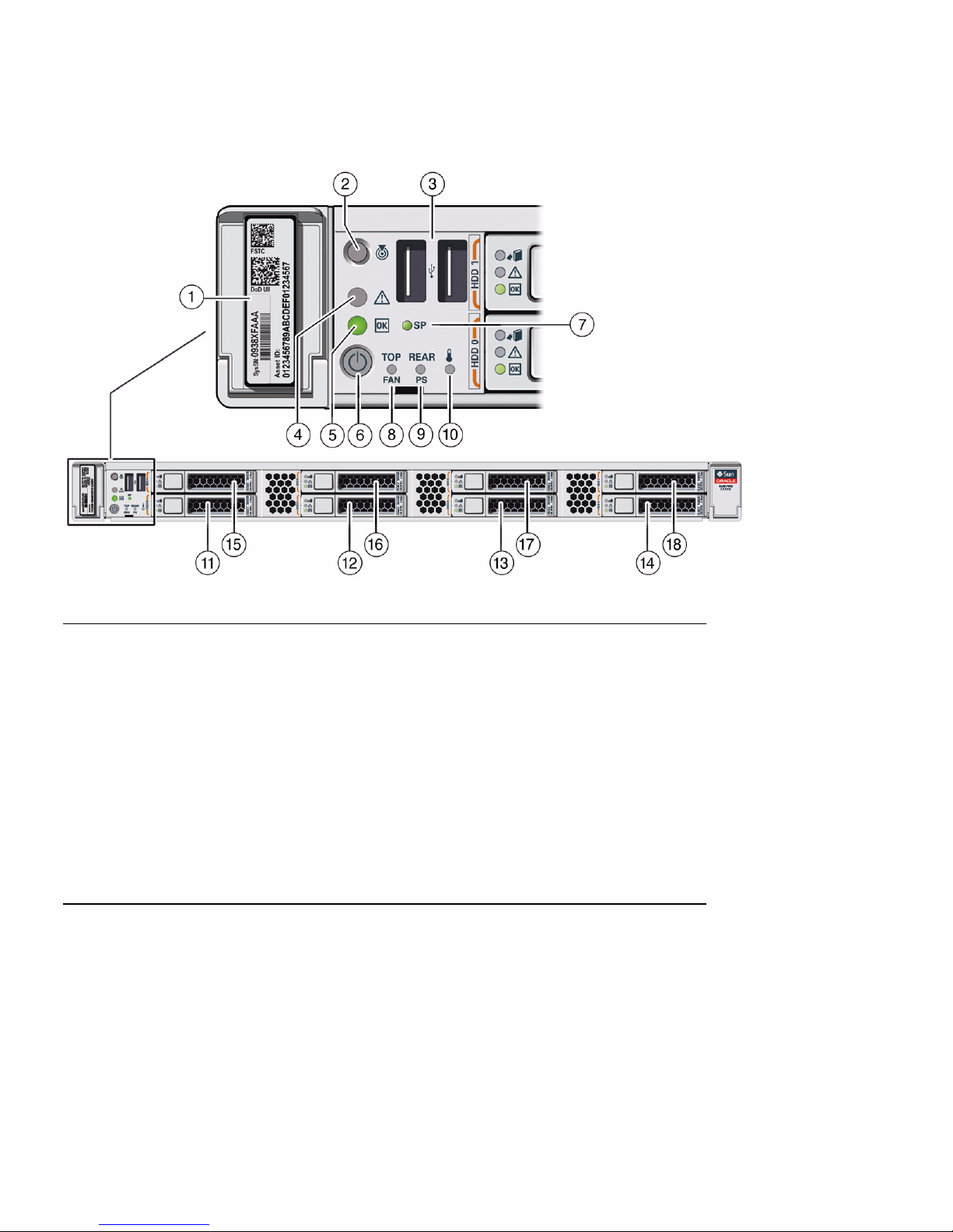
FIGURE: Front Panel With Eight 2.5-inch Drives Configuration
Figure Legend
1 Product Serial Number (PSN) label and
Radio Frequency Identification (RFID) tag
10 System Over Temperature Warning LED:
amber
2 Locate LED/button: white 11 Storage drive 0
3 USB 2.0 connectors (2) 12 Storage drive 1
4 Service Required LED: amber 13 Storage drive 2
5 Power/OK LED: green 14 Storage drive 3
6 Power button 15 Storage drive 4
7 SP OK LED: green 16 Storage drive 5
8 Fan Fault LED: amber 17 Storage drive 6
9 Power Supply (PS) Fault LED: amber 18 Storage drive 7 (In Oracle Engineered
Systems, storage drive 7 might be populated
with a remote battery module for the HBA
card.)
Related Information
■ “Front Panel With Four 3.5-inch Drives” on page 8
■ “Front Panel With Four 2.5-inch Drives and SATA DVD Drive” on page 11
■ “Back Panel Status Indicators, Connectors, and PCIe Slots” on page 12
10 Sun Server X3-2 Installation Guide • April 2014
Page 23
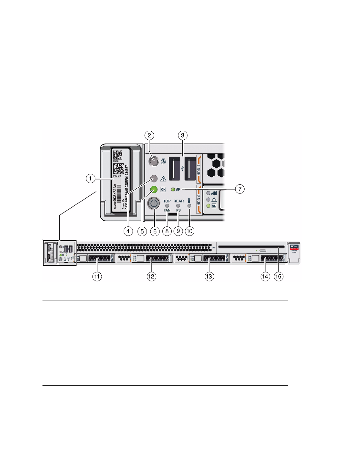
Front Panel With Four 2.5-inch Drives and SATA
DVD Drive
The following figure shows the status indicators (LEDs), connectors, and drives on
the front panel of a Sun Server X3-2 configured with four 2.5-inch storage drives and
a SATA DVD drive.
FIGURE: Front Panel With Four 2.5-inch Drives and SATA DVD Drive Configuration
Figure Legend
1 Product Serial Number (PSN) label and
Radio Frequency Identification (RFID) tag
2 Locate LED/ button: white 10 System Over Temperature Warning LED:
3 USB 2.0 connectors (2) 11 Storage drive 0
4 Service Required LED: amber 12 Storage drive 1
5 Power/OK LED: green 13 Storage drive 2
6 Power button 14 Storage drive 3
7 SP OK LED: green 15 SATA DVD drive
8 Fan Fault LED: amber 16 Not applicable
9 Power Supply (PS) Fault LED: amber
amber
About Server Features and Components 11
Page 24
Related Information
■ “Front Panel With Four 3.5-inch Drives” on page 8
■ “Front Panel With Eight 2.5-inch Drives” on page 9
■ “Back Panel Status Indicators, Connectors, and PCIe Slots” on page 12
Back Panel Status Indicators, Connectors,
and PCIe Slots
The following figure shows the Sun Server X3-2 back panel and the location of status
indicators (LEDs), connectors, and PCIe slots.
FIGURE: Server Back Panel
Figure Legend
1 Power Supply (PS) 0 9 Oracle Integrated Lights Out Manager (ILOM)
2 Power Supply (PS) 0 status indicators:
Service Required LED: amber
AC OK LED: green
3 Power Supply (PS) 1 11 Network (NET) 100/1000/10000 port: NET 3
4 Power Supply (PS) 1 status indicators:
Service Required LED: amber
AC OK LED: green
12 Sun Server X3-2 Installation Guide • April 2014
service processor (SP) network management
10/100BASE-T port (NET MGT)
10 Serial management (SER MGT)/RJ-45 serial
port
(Nonfunctional in single-processor systems.)
12 Network (NET) 100/1000/10000 port: NET 2
(Nonfunctional in single-processor systems.)
Page 25

Figure Legend (Continued)
5 System status indicators:
Locator LED: white
Service Required LED: amber
Power/OK LED: green
6 PCIe card slot 1 (Nonfunctional in
single-processor systems.)
7 PCIe card slot 2 15 USB 2.0 connectors (2)
8 PCIe card slots 3 and 4 16 DB-15 video connector
13 Network (NET) 100/1000/10000 port: NET 1
14 Network (NET) 100/1000/10000 port: NET 0
Related Information
■ “Front Panel Status Indicators, Connectors, and Drives” on page 8
■ “Server Components” on page 6
Server Management Software Overview
The following sections describe the server management software:
■ “Oracle System Assistant” on page 13
■ “Oracle ILOM Overview” on page 14
■ “UEFI BIOS Overview” on page 14
Oracle System Assistant
Oracle System Assistant enables you to set up and manage the Sun Server X3-2. The
Oracle System Assistant application is a task-based server provisioning tool that
allows you to perform initial server setup and maintenance for Oracle x86 servers.
Using Oracle System Assistant, you can install a supported Oracle Solaris, Oracle
VM, Linux, or Windows operating system, update your server to the latest software
release, and configure server hardware.
The Sun Server X3-2 might contain an internal USB flash drive that contains Oracle
System Assistant.
About Server Features and Components 13
Page 26
Oracle ILOM Overview
Oracle ILOM allows you to manage the Sun Server X3-2. Use Oracle ILOM to connect
to the server service processor (SP). The server supports Oracle Integrated Lights Out
Manager (ILOM) version 3.1.
The Oracle ILOM software resides on the server service processor. Use Oracle ILOM
software to monitor and manage server components. Oracle ILOM software
functions include:
■ Configuring network information
■ Viewing and editing hardware configurations for the SP
■ Monitoring vital system information and viewing logged events
■ Managing Oracle ILOM user accounts
You can access the server SP in either of the following ways:
■ “Log In to Oracle ILOM Remotely Using the Web Interface” on page 67
■ “Log In to Oracle ILOM Using a Local Serial Connection” on page 66
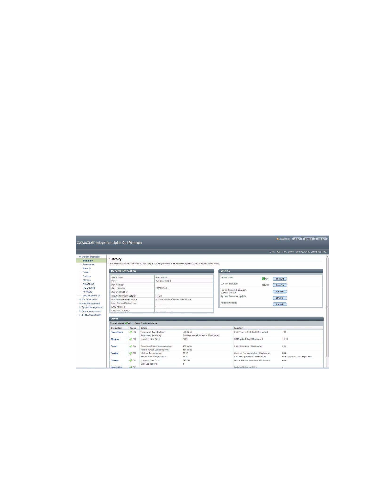
The following illustration shows an example of the web interface when you are
logged in to Oracle ILOM.
UEFI BIOS Overview
The Sun Server X3-2 contains a Unified Extensible Firmware Interface
(UEFI)-compatible BIOS that provides more boot options and configuration
capability for adapter cards than previous versions of the BIOS.
14 Sun Server X3-2 Installation Guide • April 2014
Page 27

The server also supports a legacy version of the BIOS for use with software or
adapters that do not have UEFI drivers. The legacy version is the default.
The following sections provide more information on the UEFI BIOS modes:
■ “Boot Mode Selection” on page 15
■ “Legacy BIOS Boot Mode” on page 15
■ “UEFI BIOS Boot Mode” on page 15
Refer to the Sun Server X3-2 Administration Guide, “Using Legacy BIOS or UEFI” on
page 113 for more information about UEFI BIOS.
Boot Mode Selection
Two boot modes are available for BIOS: Legacy BIOS Boot Mode and UEFI BIOS Boot
Mode. UEFI BIOS can be configured to support either UEFI or Legacy BIOS Boot
Mode. However, some devices and operating systems do not yet support UEFI BIOS
and can boot only from Legacy BIOS Boot Mode.
If you change boot modes, the boot candidates from the previous mode disappear.
The boot candidates from the new mode appear after you issue the BIOS command
Save Changes and Reset. Use the Oracle ILOM BIOS Backup and Restore function to
preserve the configuration in case you want to switch back. For information about
Oracle ILOM, refer to the Oracle Integrated Lights Out Manager (ILOM) 3.1
Documentation Library at http://www.oracle.com/pls/topic/lookup?ctx=
ilom31.
Legacy BIOS Boot Mode
Choose Legacy BIOS Boot Mode to allow host bus adapters (HBAs) to use option
ROMs. Select Legacy BIOS Boot Mode when software or adapters do not have UEFI
drivers, or the system is using option ROM. Legacy BIOS Boot Mode is the default
boot mode.
In Legacy BIOS Boot Mode, only boot candidates that support Legacy BIOS Boot
Mode appear in the BIOS Setup Utility screens in the Boot Options Priority list.
UEFI BIOS Boot Mode
Choose UEFI BIOS Boot Mode to use UEFI drivers when software and adapters have
UEFI drivers. UEFI BIOS Boot Mode is manually selected during setup. For
instructions for making the selection, refer to the Sun Server X3-2 Administration
Guide, “Using Legacy BIOS or UEFI” on page 113.
About Server Features and Components 15
Page 28

In UEFI BIOS Boot Mode, only boot candidates that support UEFI BIOS Boot Mode
appear on the BIOS Setup Utility screens in the Boot Options Priority list.
Currently, the following operating systems support UEFI BIOS Boot Mode. For
updates to this list, refer to Sun Server X3-2 Product Notes at
http://www.oracle.com/pls/topic/lookup?ctx=SunServerX3-2.
■ Oracle Solaris 11.1
■ Oracle Linux 6.x
■ Red Hat Enterprise Linux 6.x
■ SUSE Linux Enterprise Server 11 SP2
■ Microsoft Windows Server 2008
■ VMware ESXi 5.x
These operating systems can use either UEFI BIOS Boot Mode or Legacy BIOS Boot
Mode. All other operating systems must use Legacy BIOS Boot Mode. However, once
you choose a boot mode and install an operating system, if you reboot the server and
select a different boot mode, the installed image is not accessible and cannot be used.
16 Sun Server X3-2 Installation Guide • April 2014
Page 29

Preparing for Server Installation
This section provides the information you need to prepare for the server installation.
Description Links
Unpack the server and verify the accessory
kit contents.
Assemble the tools required for
installation.
Review ESD requirements and take safety
precautions.
Install any optional components into the
server.
“Shipping Inventory” on page 17
“Tools and Equipment Needed for
Installation” on page 18
“ESD and Safety Precautions” on page 18
“Optional Component Installation” on page 19
Related Information
■ “Installation Procedure Overview” on page 2
■ Sun Server X3-2 Site Planning Guide, “Preparing the Site for Installation” on page 1
■ “About Server Features and Components” on page 5
Shipping Inventory
Inspect the shipping cartons for evidence of physical damage. If a shipping carton
appears damaged, request that the carrier ’s agent be present when the carton is
opened. Keep all contents and packing material for the agent’s inspection.
The accessory kit for the Sun Server X3-2 includes the following items:
■ Power cords, packaged separately with country kit
■ Rackmount kit containing rack rails and installation instructions
■ Miscellaneous hardware, cables, and connectors
17
Page 30
■ Sun Server X3-2 Getting Started Guide
■ Legal and safety documents
Related Information
■ “Optional Component Installation” on page 19
Tools and Equipment Needed for
Installation
To install the system, you must have the following tools:
■ No. 2 Phillips screwdriver
■ ESD mat and grounding strap
In addition, you must provide a system console device, such as one of the following:
■ ASCII terminal
■ Workstation
■ Terminal server
■ Patch panel connected to a terminal server
Related Information
■ “Installing the Server Into a Rack” on page 21
ESD and Safety Precautions
Electronic equipment is susceptible to damage by static electricity. Use a grounded
antistatic wriststrap, footstrap, or equivalent safety equipment to prevent
electrostatic discharge (ESD) when you install or service the server.
Read the safety information in the Sun Server X3-2 Safety and Compliance Guide and in
the Important Safety Information for Oracle Hardware Systems before installing the
server.
18 Sun Server X3-2 Installation Guide • April 2014
Page 31
Caution – To protect electronic components from electrostatic damage, which can
permanently disable the system or require repair by service technicians, place
components on an antistatic surface, such as an antistatic discharge mat, an antistatic
bag, or a disposable antistatic mat. Wear an antistatic grounding strap connected to a
metal surface on the chassis when you work on system components.
Caution – Deploy the anti-tilt bar or legs on the equipment rack before beginning an
installation.
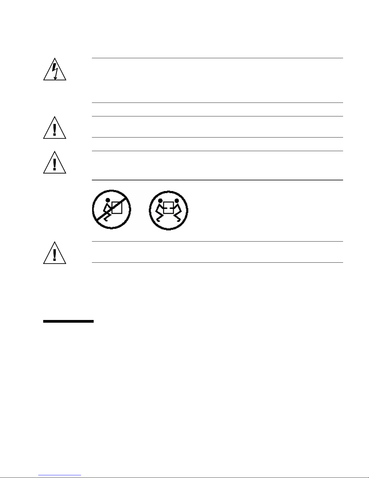
Caution – The server weighs approximately 18.1 kg (39.9 pounds). Two people are
required to lift and mount this 1 rack unit (1U) server into a rack enclosure when
using the procedures in this document.
Caution – When completing a two-person procedure, always communicate your
intentions clearly before, during, and after each step to minimize confusion.
Related Information
■ “Safety Precautions When Rackmounting the Server” on page 23
Optional Component Installation
Standard system components are installed at the factory. Optional components that
you purchased independent of the standard configuration are shipped separately,
and in most cases should be installed before you install the server in a rack.
The following optional components can be ordered and purchased separately:
■ PCIe cards
■ DDR3 DIMM memory kits
Preparing for Server Installation 19
Page 32

■ Storage drives
■ Software media
If you ordered any options that are not factory installed, refer to Sun Server X3-2
Service Manual, “About System Components” on page 18.
Supported components and their part numbers are subject to change over time and
without notice. For the most up-to-date list, go to:
https://support.oracle.com/handbook_private/
Note – This site requires an Oracle web account for access.
Click the name and model of your server. On the product page that opens for the
server, click Full Components List for a list of components.
If you ordered any options that are field-replaceable units (FRUs) or
customer-replaceable units (CRUs), refer to the service label on the top cover of the
server or the component removal and replacement procedures in the Sun Server X3-2
Service Manual, “About System Components” on page 18 for installation instructions.
Related Information
■ Sun Server X3-2 Service Manual, “About System Components” on page 18
20 Sun Server X3-2 Installation Guide • April 2014
Page 33

Installing the Server Into a Rack
This section describes how to install the server into a rack using the rail assembly in
the rackmount kit. Perform these procedures if you purchased the rail assembly.
Description Links
Complete all installation
prerequisite tasks.
Check that your rack meets the
requirements for installation of this
server.
Review safety precautions. “Safety Precautions When Rackmounting the
Verify that you have received all
components of the rackmount kit.
Stabilize the rack. “Stabilize the Rack for Installation” on page 25
Install mounting brackets onto the
server.
Mark the rackmount location. “Mark the Rackmount Location” on page 28
Attach the tool-less slide-rail
assembly to the rack.
Install the server into the slide-rail
assembly.
(Optional) Install the cable
management arm for routing server
cables.
“Installation Prerequisites” on page 22
“Rack Requirements” on page 22
Server” on page 23
“Rackmount Kit Contents” on page 24
“Install Mounting Brackets” on page 26
“Attach Tool-less Slide-Rail Assemblies” on page 29
“Install the Server Into the Slide-Rail Assemblies”
on page 32
• “Install the Second-Generation Cable
Management Arm” on page 35
• “Remove the Second-Generation Cable
Management Arm” on page 46
• “Install the First-Generation Cable Management
Arm” on page 50
Related Information
■ “About the Installation Procedure” on page 1
■ “Preparing for Server Installation” on page 17
21
Page 34

■ Sun Server X3-2 Site Planning Guide, “Preparing the Site for Installation” on page 1
Installation Prerequisites
Ensure that the following tasks are complete before you start the rackmount
procedures:
■ Install all optional components purchased for the server. See “Optional
Component Installation” on page 19.
■ Ensure that your site meets the required electrical and environmental
requirements. See the Sun Server X3-2 Site Planning Guide, “Preparing the Site for
Installation” on page 1.
Rack Requirements
The rack into which you install the Sun Server X3-2 must meet the requirements
listed in the following table.
TABLE: Rack Requirements
Item Requirement
Structure Four-post rack (mounting at both front and rear).
Supported rack types: square hole (9.5 mm) and
round hole (M6 or 1/4-20 threaded only.
Two-post racks are not compatible.
Rack horizontal opening and unit
vertical pitch
Distance between front and rear
mounting planes
Clearance depth in front of front
mounting plane
Clearance depth behind front
mounting plane
Conforms to ANSI/EIA 310-D-1992 or IEC 60927
standards.
Minimum 610 mm and maximum 915 mm
(24 inches to 36 inches).
Distance to front cabinet door is at least 25.4 mm
(1 inch).
Distance to rear cabinet door is at least 900 mm (35.43
inches) with the cable management arm, or 800 mm
(31.5 inches) without the cable management arm.
22 Sun Server X3-2 Installation Guide • April 2014
Page 35

TABLE: Rack Requirements (Continued)
Item Requirement
Clearance width between front and
rear mounting planes
Minimum clearance for service access • Clearance, front of server: 123.2 cm (48.5 inches)
Server dimensions Depth: (not including PSU handle): 737.0 mm (29.0
Distance between structural supports and cable
troughs is at least 456 mm (18 inches).
• Clearance, rear of server: 91 cm (36 inches)
inches).
Width: (not including ears): 436.5 mm (17.19 inches).
Height: 42.6 mm (1.68 inches).
Related Information
■ “Preparing for Server Installation” on page 17
■ Sun Server X3-2 Site Planning Guide, “Preparing the Site for Installation” on page 1
Safety Precautions When Rackmounting
the Server
This section describes safety precautions you must follow when installing the server
into a rack.
Caution – Deploy the anti-tilt bar or legs on the equipment rack before beginning an
installation.
Caution – Always load equipment into a rack from the bottom up so that the rack
will not become top-heavy and tip over. Deploy your rack’s anti-tilt bar to prevent
the rack from tipping during equipment installation.
Caution – Elevated operating ambient temperature: If the server is installed in a
closed or multi-unit rack assembly, the operating ambient temperature of the rack
environment might be greater than room ambient temperature. Therefore,
consideration should be given to installing the equipment in an environment
Installing the Server Into a Rack 23
Page 36

compatible with the maximum ambient temperature (Tma) specified for the server.
For server environmental requirements, refer to Sun Server X3-2 Site Planning Guide,
“Preparing the Site for Installation” on page 1.
Caution – Reduced airflow: Installation of the equipment in a rack should be such
that the amount of airflow required for safe operation of the equipment is not
compromised.
Caution – Mechanical loading: Mounting of the equipment in the rack should be
such that a hazardous condition is not created due to uneven mechanical loading.
Caution – Circuit overloading: Consideration should be given to the connection of
the equipment to the supply circuit and the effect that overloading of the circuits
might have on over-current protection and supply wiring. Appropriate consideration
of equipment nameplate power ratings should be used when addressing this
concern.
Caution – Reliable earthing: Reliable earthing of rackmounted equipment should
be maintained. Particular attention should be given to supply connections other than
direct connections to the branch circuit (for example, use of power strips).
Caution – Slide-rail-mounted equipment is not to be used as a shelf or a work space.
Related Information
■ “ESD and Safety Precautions” on page 18
Rackmount Kit Contents
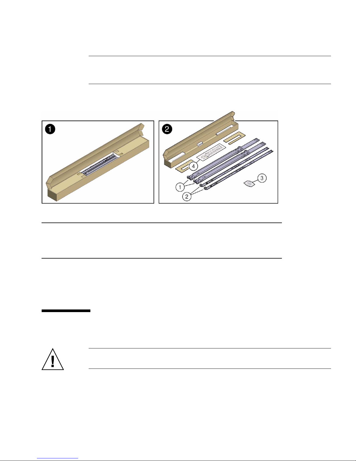
The rackmount kit contains two slide-rails, two mounting brackets, and optional
securing screws.
24 Sun Server X3-2 Installation Guide • April 2014
Page 37
Note – Refer to the rackmount kit installation card for instructions on how to install
your server into a four-post rack, using the slide-rail and cable management arm
options.
FIGURE: Tool-less Rackmount Kit Contents
Figure Legend
1 Slide-rails
2 Mounting brackets
3 Four M4 x 5 fine-pitch mounting bracket securing screws (optional)
4 Installation card
Related Information
■ “Rack Requirements” on page 22
▼ Stabilize the Rack for Installation
Caution – To reduce the risk of personal injury, stabilize the rack cabinet, and
extend all anti-tilt devices before installing the server.
Refer to your rack documentation for detailed instructions for the following steps.
1. Open and remove the front and rear doors from the rack cabinet.
Installing the Server Into a Rack 25
Page 38

Note – The front and rear doors need to be removed only if they impinge on the
mounting bay.
2. To prevent the rack cabinet from tipping during the installation, fully extend
the rack cabinet’s anti-tilt legs or anti-tilt bar, which are located at the bottom
front of the rack cabinet.
3. If there are leveling feet beneath the rack cabinet to prevent it from rolling,
extend these leveling feet fully downward to the floor.
Related Information
■ “Safety Precautions When Rackmounting the Server” on page 23
■ Your rack cabinet documentation
■ Sun Server X3-2 Safety and Compliance Guide at
http://docs.oracle.com/cd/E22368_01/index.html
■ Sun Server X3-2 Site Planning Guide, “Preparing the Site for Installation” on page 1
▼ Install Mounting Brackets
To install the mounting brackets onto the sides of the server:
1. Position a mounting bracket against the chassis so that the slide-rail lock is at
the server front, and the five keyhole openings on the mounting bracket are
aligned with the five locating pins on the side of the chassis.
26 Sun Server X3-2 Installation Guide • April 2014
Page 39
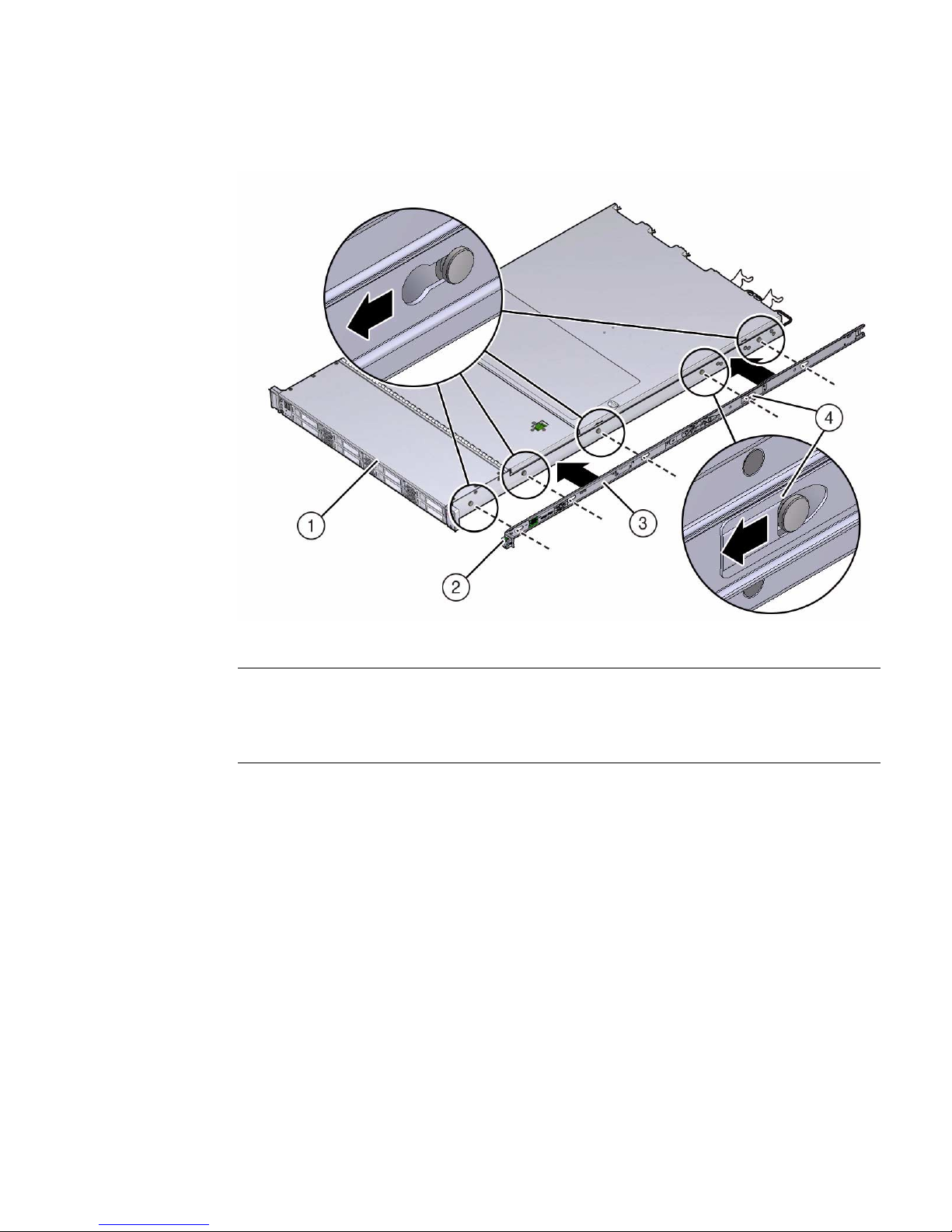
FIGURE: Aligning the Mounting Bracket With the Server Chassis
Figure Legend
1 Chassis front
2 Slide-rail lock
3 Mounting bracket
4 Mounting bracket clip
2. With the heads of the five chassis locating pins protruding through the five
keyhole openings in the mounting bracket, pull the mounting bracket toward
the front of the chassis until the mounting bracket clip locks into place with an
audible click.
3. Verify that the rear locating pin has engaged the mounting bracket clip.
4. Repeat Step 1 through Step 3 to install the remaining mounting bracket on the
other side of the server.
Related Information
■ “Mark the Rackmount Location” on page 28
■ “Attach Tool-less Slide-Rail Assemblies” on page 29
Installing the Server Into a Rack 27
Page 40
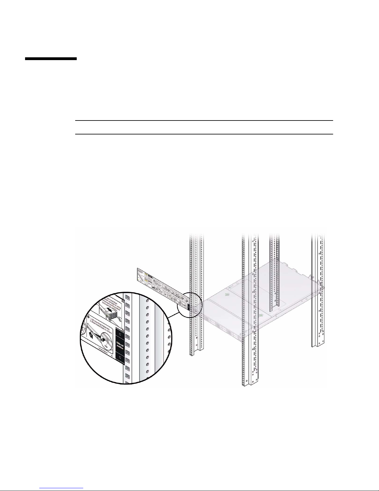
▼ Mark the Rackmount Location
Use the rackmount installation card to identify the correct mounting holes for the
slide-rails.
Note – Load the rack from bottom to top.
1. Ensure that there is at least 1 rack unit (1U) of vertical space in the rack cabinet
to install the server.
See “Rack Requirements” on page 22.
2. Place the rackmount installation card against the front rails.
The bottom edge of the card corresponds to the bottom edge of the server.
Measure up from the bottom of the installation card.
FIGURE: Rackmount Installation Card Template
3. Mark the mounting holes for the front slide-rails.
4. Mark the mounting holes for the rear slide-rails.
28 Sun Server X3-2 Installation Guide • April 2014
Page 41

Related Information
■ “Rack Requirements” on page 22
■ “Install Mounting Brackets” on page 26
■ “Attach Tool-less Slide-Rail Assemblies” on page 29
▼ Attach Tool-less Slide-Rail Assemblies
Use this procedure to attach tool-less slide-rail assemblies to the rack.
1. Orient the slide-rail assembly so that the ball-bearing track is forward and
locked in place.
Installing the Server Into a Rack 29
Page 42
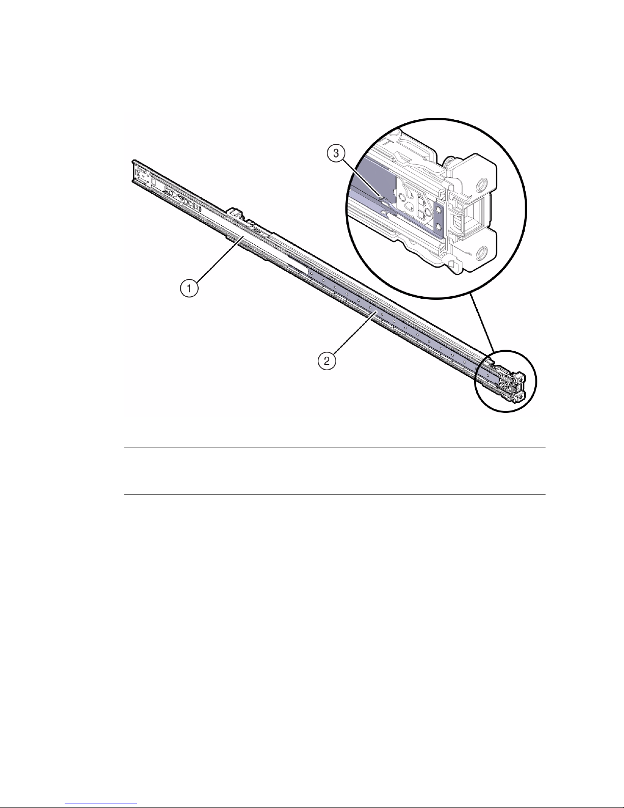
FIGURE: Orienting the Slide-Rail With the Ball-Bearing Track
Figure Legend
1 Slide-rail
2 Ball-bearing track
3 Locking mechanism
2. Starting with either the left or right side of the rack, align the rear of the
slide-rail assembly against the inside of the rear rack rail, and push until the
assembly locks into place with an audible click.
30 Sun Server X3-2 Installation Guide • April 2014
Page 43
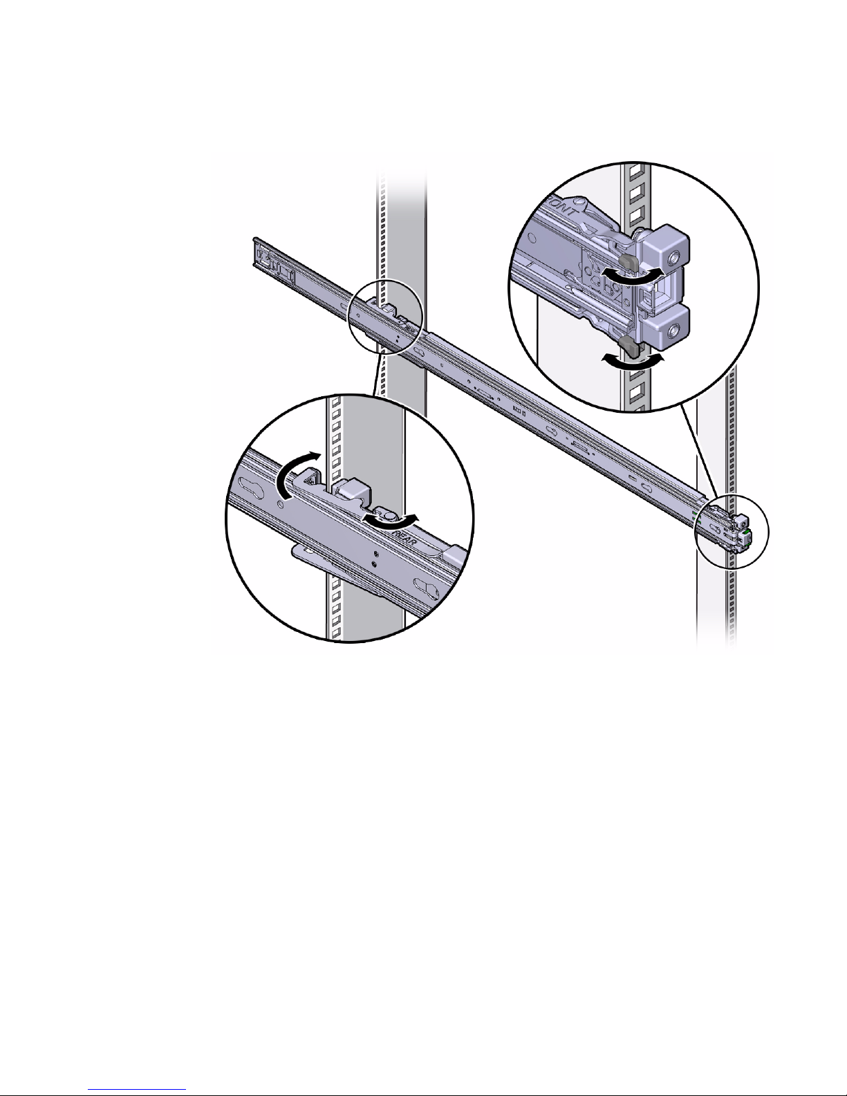
FIGURE: Aligning the Slide-Rail Assembly With the Rack
3. Align the front of the slide-rail assembly against the outside of the front rack
rail, and push until the assembly locks into place with an audible click.
4. Repeat Step 1 through Step 3 to attach the slide-rail assembly to the other side of
the rack.
Related Information
■ “Install Mounting Brackets” on page 26
■ “Mark the Rackmount Location” on page 28
■ “Install the Server Into the Slide-Rail Assemblies” on page 32
Installing the Server Into a Rack 31
Page 44
▼ Install the Server Into the Slide-Rail
Assemblies
Use this procedure to install the server chassis, with mounting brackets, into the
slide-rail assemblies that are mounted to the rack.
Caution – This procedure requires a minimum of two people because of the weight
of the server. Attempting this procedure alone could result in equipment damage or
personal injury.
Caution – Always load equipment into a rack from the bottom up so that the rack
will not become top-heavy and tip over. Extend your rack’s anti-tilt bar to prevent
the rack from tipping during equipment installation.
1. Push the slide-rails as far as possible into the slide-rail assemblies in the rack.
2. Position the server so that the rear ends of the mounting brackets are aligned
with the slide-rail assemblies that are mounted in the rack.
3. Insert the mounting brackets into the slide-rails, and then push the server into
the rack until the mounting brackets encounter the slide-rail stops
(approximately 30 cm, or 12 inches).
32 Sun Server X3-2 Installation Guide • April 2014
Page 45
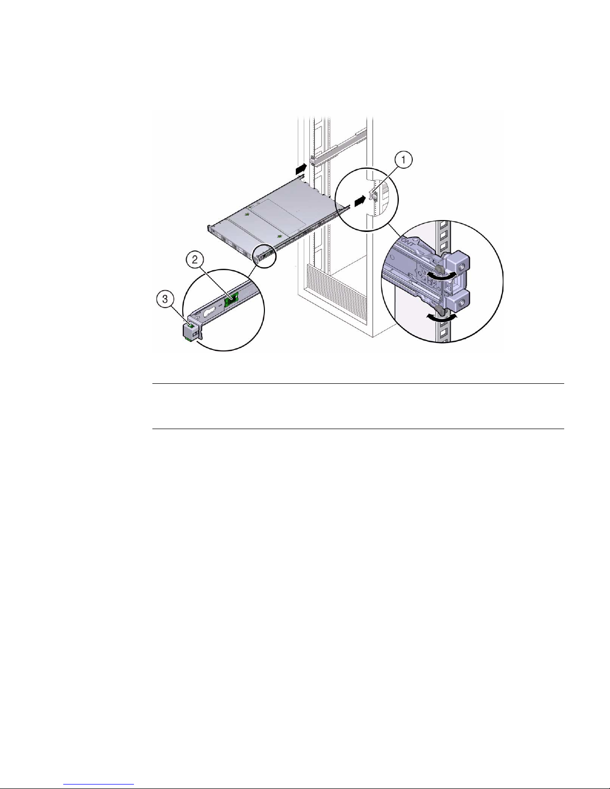
FIGURE: Inserting the Server With Mounting Brackets Into the Slide-Rails
Figure Legend
1 Inserting mounting bracket into slide-rail
2 Slide-rail release button
3 Slide-rail lock
4. Simultaneously push and hold the green slide-rail release buttons on each
mounting bracket while you push the server into the rack. Continue pushing
the server into the rack until the slide-rail locks (on the front of the mounting
brackets) engage the slide-rail assemblies.
You will hear an audible click.
Installing the Server Into a Rack 33
Page 46
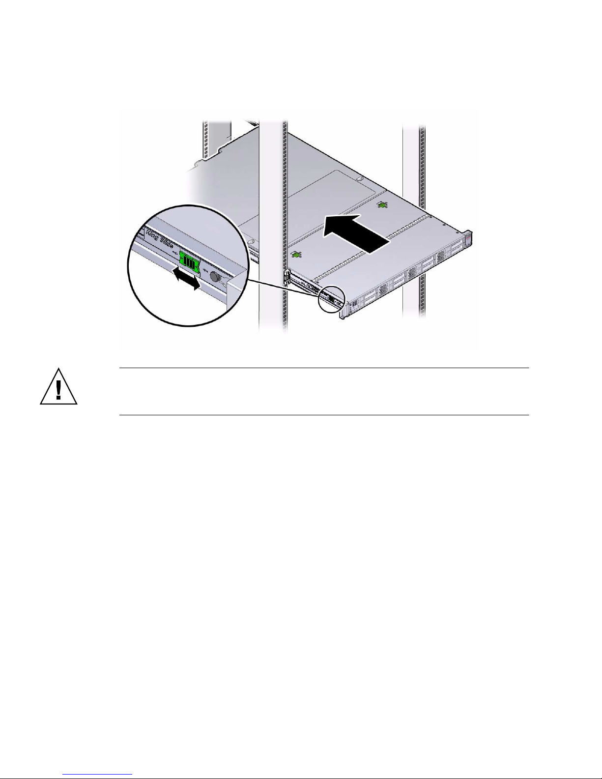
FIGURE: Sliding the Server Into the Rack
Caution – Verify that the server is securely mounted in the rack and that the
slide-rail locks are engaged with the mounting brackets before you install the
optional cable management arm.
Related Information
■ “Install the First-Generation Cable Management Arm” on page 50
■ “Install the Second-Generation Cable Management Arm” on page 35
34 Sun Server X3-2 Installation Guide • April 2014
Page 47
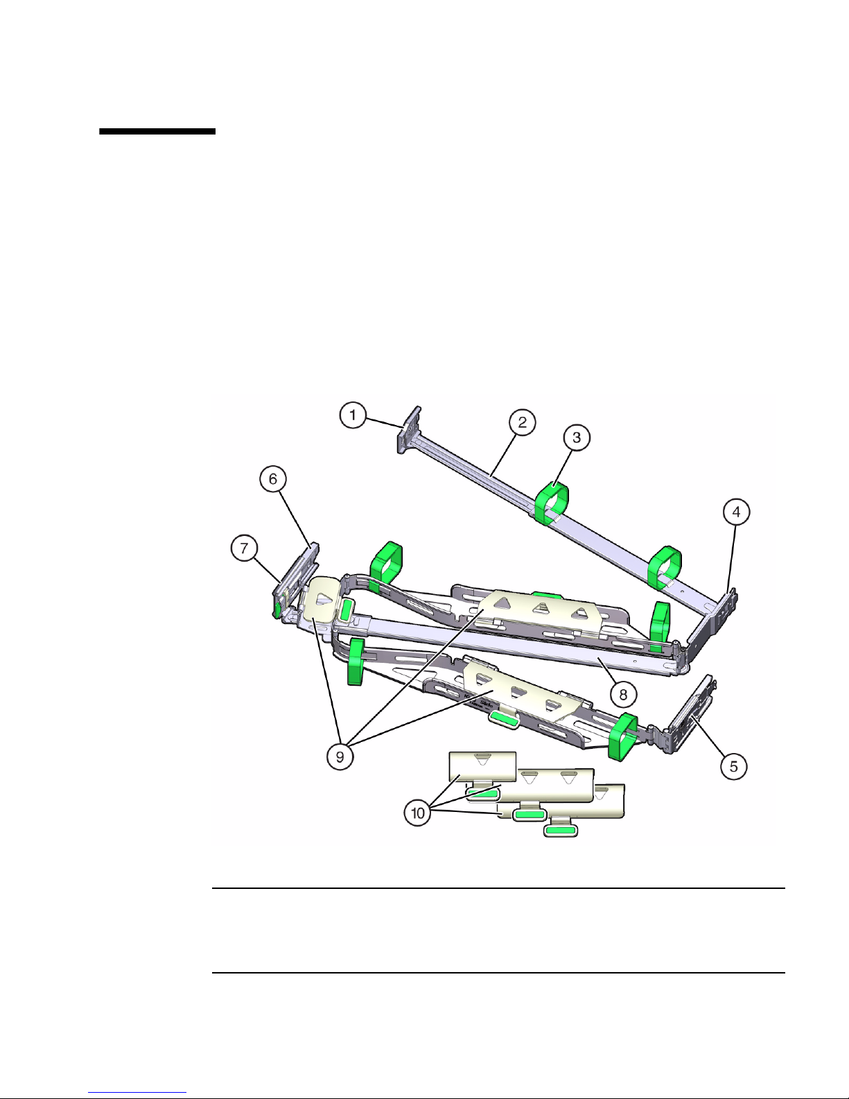
▼ Install the Second-Generation Cable
Management Arm
Follow this procedure to install the second-generation cable management arm
(CMA), which you can use to manage cables connected to the rear of the server.
1. Unpack the CMA.
The following figure shows the second-generation CMA components.
FIGURE: Second-Generation CMA Components
Figure Legend
1 Connector A
2 Front slide bar
3 Velcro straps (6)
4 Connector B
Installing the Server Into a Rack 35
Page 48

Figure Legend (Continued)
5 Connector C
6 Connector D
7 Slide-rail latching bracket (used with connector D)
8 Rear slide bar
9 Sun Server X3-2 cable covers
10 Sun Server X3-2L cable covers
2. Ensure that the correct cable covers for your server are installed on the CMA.
■ The Sun Server X3-2 (1U system) uses the flat cable covers.
■ The Sun Server X3-2L (2U system) uses the round cable covers.
Note – The CMA ships with three, flat cable covers installed. If you are going to
install the CMA on a Sun Server X3-2L, you need to remove the flat cable covers and
install the round cable covers.
3. If you are installing the CMA on a Sun Server X3-2L, remove the flat cable
covers and install the round cable covers; otherwise proceed to the next step.
To remove the flat cable covers and install the round cable covers, perform these
steps:
a. Lift up on the cable cover handle (the handle is colored green) and open it
180 degrees to the horizontal position as shown in the following figure
[frames 1 and 2].
Note – The CMA has three cable covers, two with two hinges (one of which is
shown the following figure), and one with a single hinge. All three cable covers are
shown in FIGURE: Second-Generation CMA Components on page 35.
36 Sun Server X3-2 Installation Guide • April 2014
Page 49
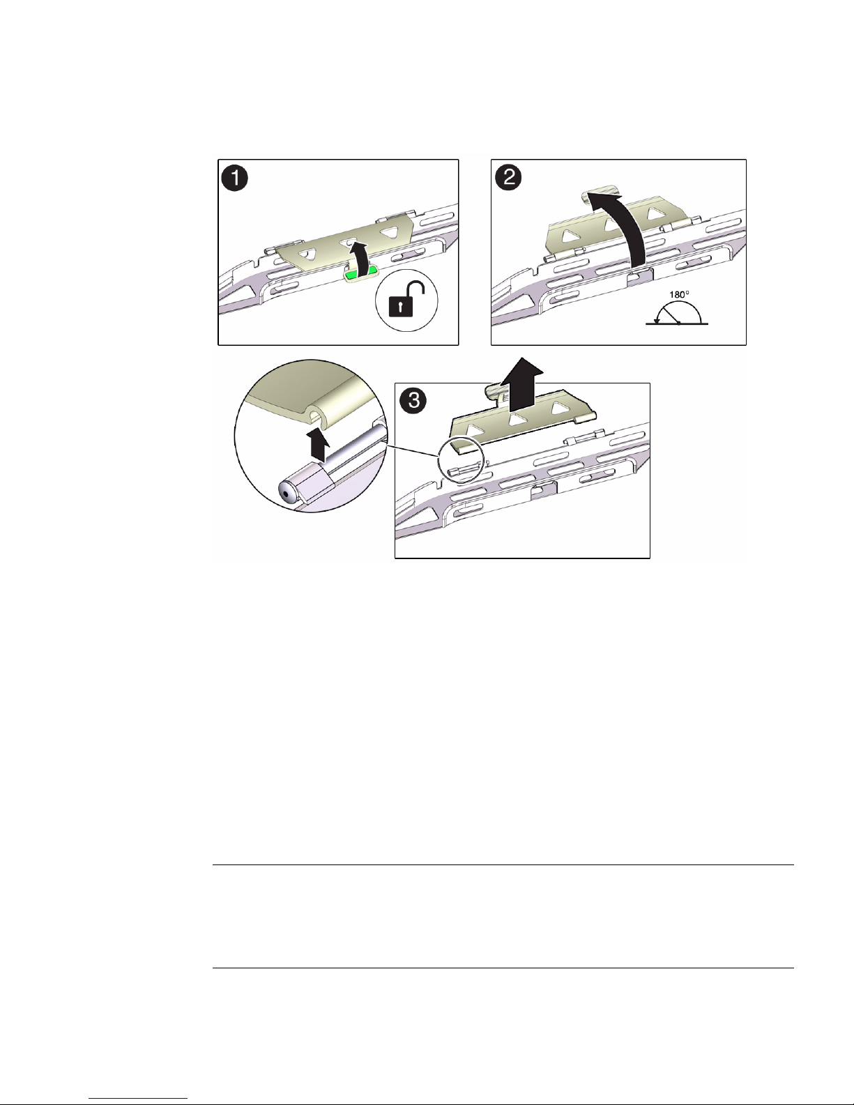
FIGURE: Removing the CMA Flat Cable Covers
b. Apply upward pressure to the outside edge of each hinge connector until the
hinge connector comes off the hinge [frame 3].
c. Repeat Step a and Step b to remove all three cable covers.
d. One at a time, position each round cable cover horizontally over the hinges,
and align the hinge connectors with the hinges.
e. Using your thumb, apply downward pressure on each hinge connector to
snap the hinge connector into place.
f. Swing the cable covers down and press down on the cable cover handle to
lock them into the closed position.
4. Ensure that the six Velcro straps are threaded into the CMA as shown in
FIGURE: Second-Generation CMA Components on page 35.
Note – Ensure that the two Velcro straps located on the front slide bar are threaded
through the opening in the top of the slide bar as shown in FIGURE:
Second-Generation CMA Components on page 35. This prevents the Velcro straps
from interfering with the expansion and contraction of the slide bar when the server
is extended out of the rack and returned into the rack.
Installing the Server Into a Rack 37
Page 50
5. To make it easier to install the CMA, extend the server approximately 13 cm (5
inches) out of the front of the rack.
6. Take the CMA to the back of the equipment rack, and ensure that you have
adequate room to work at the back of the server.
Note – References to “left” or “right” in this procedure assume that you are facing
the back of the equipment rack.
Note – Throughout this installation procedure, support the CMA and do not allow it
to hang under its own weight until it is secured at all four attachment points.
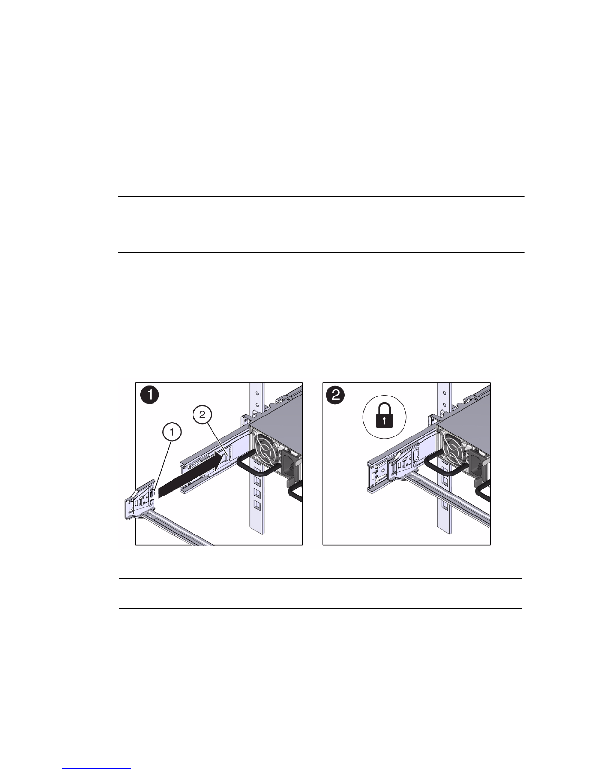
7. Insert the CMA’s connector A into the front slot on the left slide-rail until it
locks into place with an audible click [frames 1 and 2].
The connector A tab (see callout 1) goes into the slide-rail’s front slot (callout 2).
Gently tug on the left side of the front slide bar to verify that connector A is
properly seated.
FIGURE: Installing Connector A Into the Left Slide-Rail
Figure Legend
1 Connector A tab
2 Left slide-rail front slot
38 Sun Server X3-2 Installation Guide • April 2014
Page 51
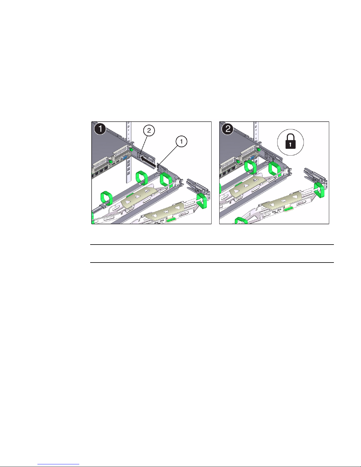
8. Insert the CMA’s connector B into the front slot on the right slide-rail until it
locks into place with an audible click [frames 1 and 2].
The connector B tab (callout 1) goes into the slide-rail front slot (callout 2).
Gently tug on the right side of the front slide bar to verify that connector B is
properly seated.
FIGURE: Installing Connector B Into the Right Slide-Rail
Figure Legend
1 Connector B tab
2 Right slide-rail front slot
9. To install the CMA’s connector C into the right slide-rail, perform the following
steps:
a. Align connector C with the slide-rail so that the locking spring (callout 1) is
positioned inside (server side) of the right slide-rail [frame 1].
Installing the Server Into a Rack 39
Page 52
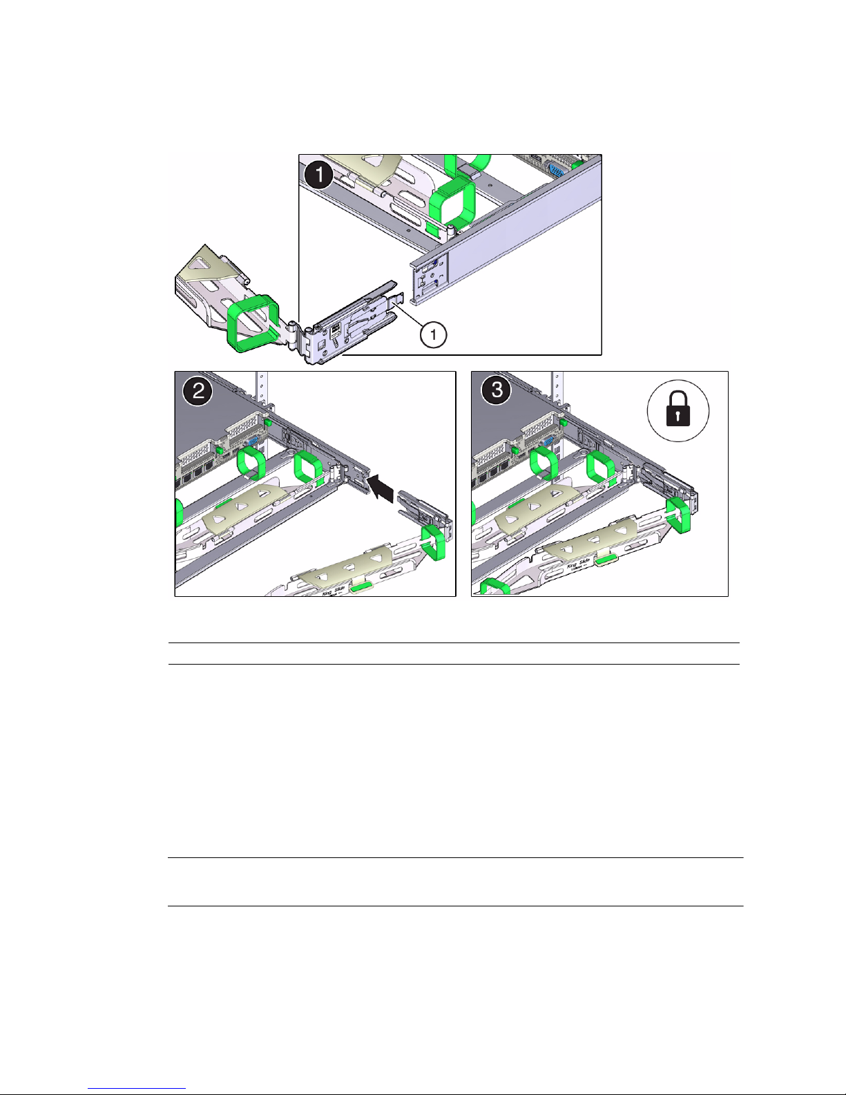
FIGURE: Installing Connector C Into the Right Side-Rail
Figure Legend
1 Connector C locking spring
b. Insert connector C into the right side-rail until it locks into place with an
audible click [frames 2 and 3].
c. Gently tug on the right side of the CMA’s rear slide bar to verify that
connector C is properly seated.
10. To prepare the CMA’s connector D for installation, remove the tape that secures
the slide-rail latching bracket to connector D and ensure that the latching
bracket is properly aligned with connector D [frames 1 and 2].
Note – The CMA is shipped with the slide-rail latching bracket taped to connector
D. You must remove the tape before you install this connector.
40 Sun Server X3-2 Installation Guide • April 2014
Page 53
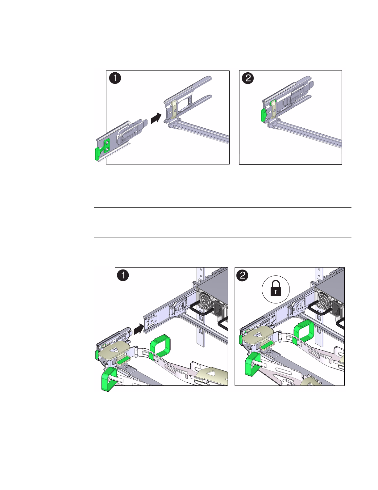
FIGURE: Aligning the CMA Slide-Rail Latching Bracket With Connector D
11. While holding the slide-rail latching bracket in place, insert connector D and its
associated slide-rail latching bracket into the left slide-rail until connector D
locks into place with an audible click [frames 1 and 2].
Note – When inserting connector D into the slide-rail, the preferred and easier
method is to install connector D and the latching bracket as one assembly into the
slide-rail.
FIGURE: Installing Connector D Into the Left Slide-Rail
12. Gently tug on the left side of the CMA’s rear slide bar to verify that connector D
is properly seated.
Installing the Server Into a Rack 41
Page 54

Note – The slide-rail latching bracket has a green release tab. This tab is used to
release and remove the latching bracket so that you can remove connector D.
13. Gently tug on the four CMA connection points to ensure that the CMA
connectors are fully seated before you allow the CMA to hang by its own
weight.
14. To verify that the slide-rails and the CMA are operating properly before routing
cables through the CMA, perform the following steps:
a. To prevent the rack from tipping forward when the server is extended, extend
all rack anti-tilt devices.
Caution – To reduce the risk of personal injury, stabilize the rack cabinet and extend
all anti-tilt devices before extending the server from the rack.
For instructions for stabilizing the rack, see “Stabilize the Rack for Installation”
on page 25.
b. Pull the server from the front of the rack until the CMA is fully extended.
42 Sun Server X3-2 Installation Guide • April 2014
Page 55
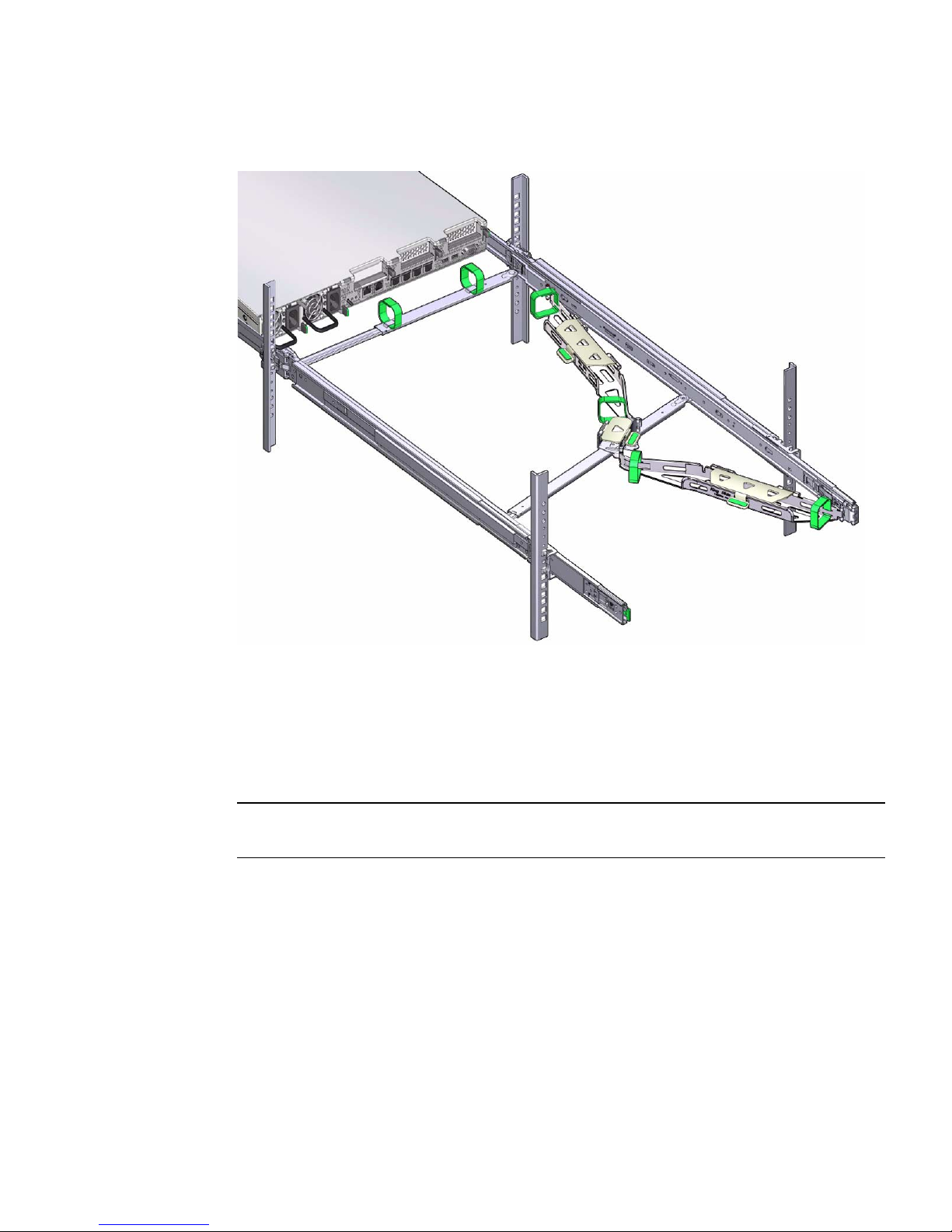
FIGURE: CMA Fully Extended
15. To return the server to the rack, perform the following steps:
a. Simultaneously pull and hold the two green release tabs (one on each side of
the server) toward the front of the server (see the following figure) while you
push the server into the rack. As you push the server into the rack, verify that
the CMA retracts without binding.
Note – To pull the green release tabs, place your finger in the center of each tab, not
on the end, and apply pressure as you pull the tab toward the front of the server.
Installing the Server Into a Rack 43
Page 56
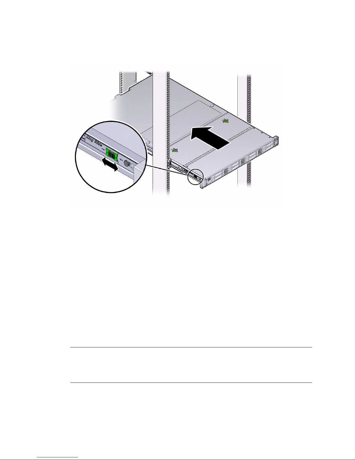
FIGURE: Location of Slide-Rail Release Tabs
b. Continue pushing the server into the rack until the slide-rail locks (on the
front of the server) engage the slide-rail assemblies.
You will hear an audible click when the server is in the normal rack position.
16. Connect cables to the server, as required.
Instructions for connecting the server cables are provided in “Cabling the Server”
on page 57.
17. Open the CMA cable covers, route server cables through the CMA’s cable
troughs, close the cable covers, and secure the cables with the six Velcro straps.
Route the cables through the cable troughs in this order:
a. First through the front-most cable trough.
b. Then through the small cable trough.
c. Then through the rear-most cable trough
Note – When securing the cables with the Velcro straps located on the front slide bar,
ensure that the Velcro straps do not wrap around the bottom of the slide bar;
otherwise, expansion and contraction of the slide bar might be hindered when the
server is extended from the rack and returned to the rack.
44 Sun Server X3-2 Installation Guide • April 2014
Page 57
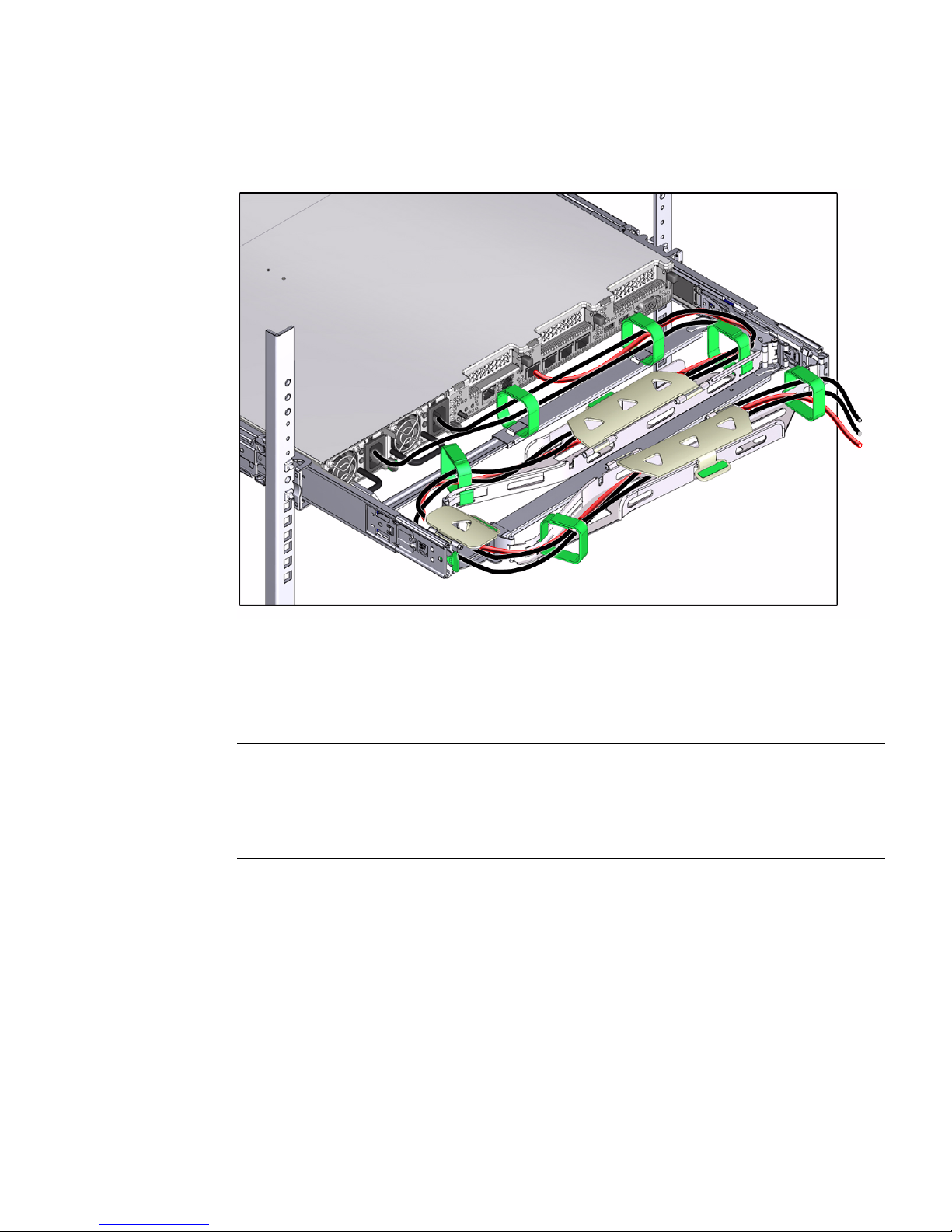
FIGURE: CMA With Cables Installed, Cable Covers Closed, and Cables Secured With
Velcro straps
18. Ensure that the secured cables do no extend above the top or below the bottom
of the server to which they are attached; otherwise, the cables might snag on
other equipment installed in the rack when the server is extended from the rack
or returned to the rack.
Note – If necessary, bundle the cables with additional Velcro straps to ensure that
they stay clear of other equipment. If you need to install additional Velcro straps,
wrap the straps around the cables only, not around any of the CMA components;
otherwise, expansion and contraction of the CMA slide bars might be hindered when
the server is extended from the rack and returned to the rack.
Related Information
■ “Remove the Second-Generation Cable Management Arm” on page 46
Installing the Server Into a Rack 45
Page 58

▼ Remove the Second-Generation Cable
Management Arm
Follow this procedure to remove the second-generation cable management arm
(CMA).
Before you begin this procedure, refer to FIGURE: Second-Generation CMA
Components on page 35 and identify CMA connectors A, B, C, and D. You should
disconnect the CMA connectors in the reverse order in which you installed them,
that is, disconnect connector D first, then C, then B, and finally A.
Note – References to “left” or “right” in this procedure assume that you are facing
the back of the equipment rack.
Note – Throughout this procedure, once you disconnect any of the CMA’s four
connectors, do not allow the CMA to hang under its own weight.
1. To prevent the rack from tipping forward when the server is extended, extend
all rack anti-tilt devices.
Caution – To reduce the risk of personal injury, stabilize the rack cabinet and extend
all anti-tilt devices before extending the server from the rack.
For instructions for stabilizing the rack, see “Stabilize the Rack for Installation” on
page 25.
2. To make it easier to remove the CMA, extend the server approximately 13 cm (5
inches) out of the front of the rack.
3. To remove the cables from the CMA, do the following:
a. Disconnect all cables from the rear of the server.
b. If applicable, remove any additional Velcro straps that were installed to
bundle the cables.
c. Unwrap the six Velcro straps that are securing the cables.
d. Open the three cable covers to the fully opened position.
e. Remove the cables from the CMA and set them aside.
46 Sun Server X3-2 Installation Guide • April 2014
Page 59

4. To disconnect connector D, perform the following steps:
a. Press the green release tab (callout 1) on the slide-rail latching bracket
toward the left and slide the connector D out of the left slide-rail [frames 1
and 2].
Note – When you slide connector D out of the left slide-rail, the slide-rail latching
bracket portion of the connector remains in place. You will disconnect it in the next
step.
Note – Once you have disconnected connector D, you must not allow the CMA to
hang under its own weight. Throughout the remainder of this procedure, the CMA
must be supported until all the remaining connectors are disconnected and the CMA
can be placed on a flat surface.
Installing the Server Into a Rack 47
Page 60
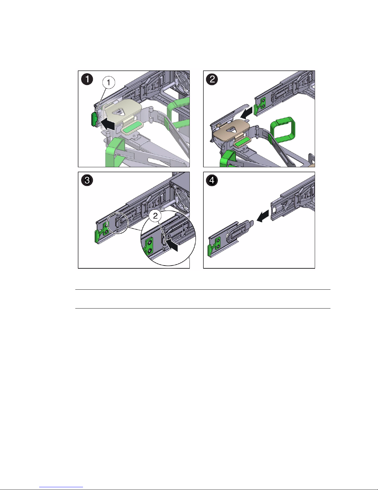
FIGURE: Disconnecting Connector D
Figure Legend
1 Connector D release tab (green)
2 Slide-rail latching bracket release tab (labeled PUSH)
b. Use your right hand to support the CMA and use your left thumb to push in
(toward the left) on the connector D latching bracket release tab labeled
PUSH (callout 2), and pull the latching bracket out of the left slide-rail and
put it aside [frames 3 and 4].
5. To disconnect connector C, perform the following steps:
a. Place your left arm under the CMA to support it.
b. Use your right thumb to push in (toward the right) on the connector C release
tab labeled PUSH (callout 1), and pull connector C out of the right slide-rail
[frame 1 and 2].
48 Sun Server X3-2 Installation Guide • April 2014
Page 61
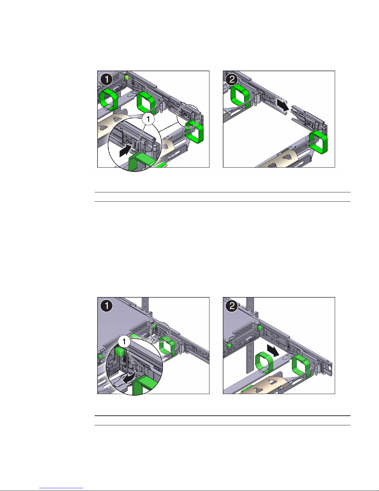
FIGURE: Disconnecting Connector C
Figure Legend
1 Connector C release tab (labeled PUSH)
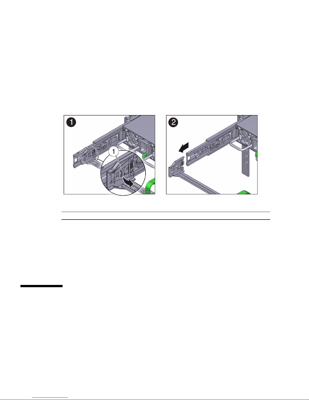
6. To disconnect connector B, perform the following steps:
a. Place your right arm under the CMA to support it and grasp the rear end of
connector B with your right hand.
b. Use your left thumb to pull the connector B release lever to the left away
from the right slide-rail (callout 1) and use your right hand to pull the
connector out of the slide-rail [frames 1 and 2].
FIGURE: Disconnecting Connector B
Figure Legend
1 Connector B release lever
Installing the Server Into a Rack 49
Page 62
7. To disconnect connector A, perform the following steps:
a. Place your left arm under the CMA to support it and grasp the rear end of
connector A with your left hand.
b. Use your right thumb to pull the connector A release lever to the right away
from the left slide-rail (callout 1), and use your left hand to pull the
connector out of the slide-rail [frames 1 and 2].
FIGURE: Disconnecting Connector A
Figure Legend
1 Connector A release lever
8. Remove the CMA from the rack and place it on a flat surface.
9. Go to the front of the server and push it back into the rack.
Related Information
“Install the Second-Generation Cable Management Arm” on page 35
▼ Install the First-Generation Cable
Management Arm
Use this procedure to install the cable management arm (CMA), which you can use
to route the server cables in the rack.
50 Sun Server X3-2 Installation Guide • April 2014
Page 63
Note – If you installed the second-generation CMA as described in “Install the
Second-Generation Cable Management Arm” on page 35, you can ignore this task.
The server only ships with one CMA; the second-generation CMA is the newer
version.
1. Unpack the CMA parts.
2. Take the CMA to the back of the equipment rack, and ensure that you have
adequate room to work around the back of the server.
Note – References to “left” or “right” in this procedure assume that you are facing
the back of the equipment rack.
3. Remove the tape to separate the parts of the CMA.
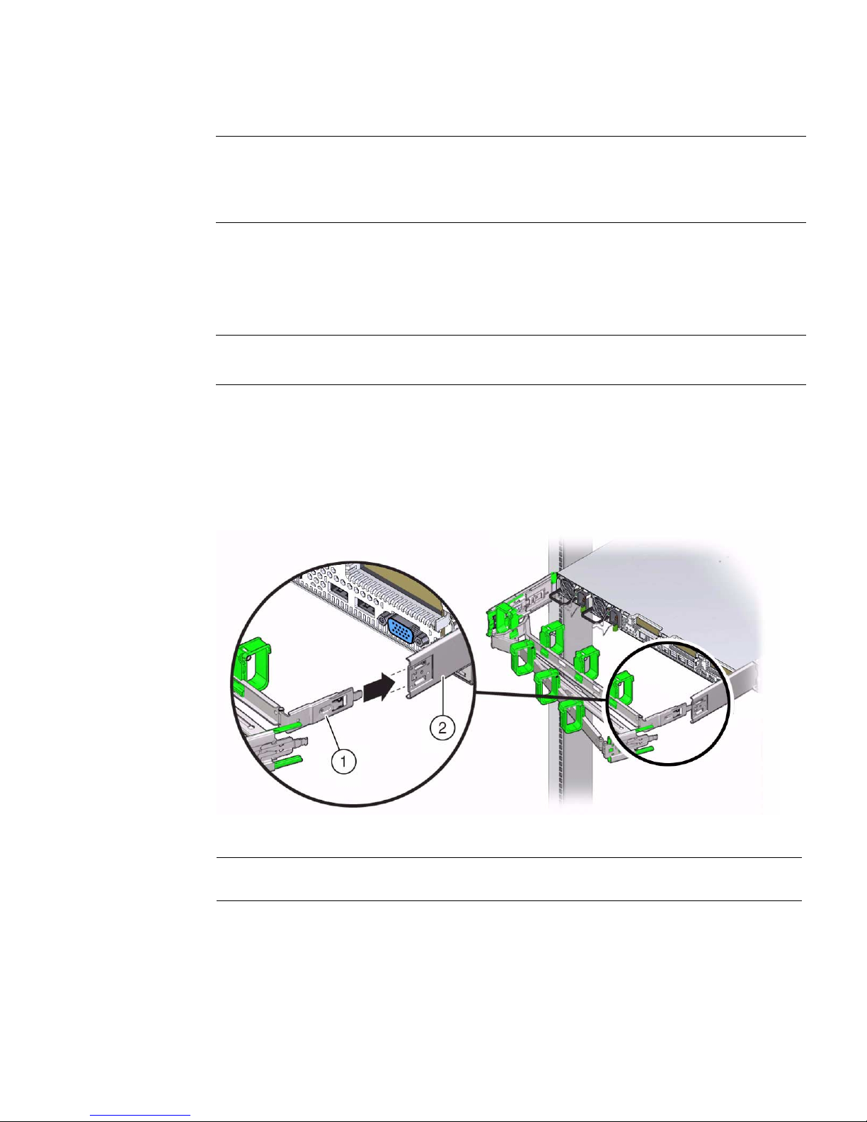
4. Insert the CMA’s mounting bracket connector into the back of the right
slide-rail until the connector locks into place with an audible click.
FIGURE: Inserting the CMA Mounting Bracket Into the Back of the Right Slide-Rail
Figure Legend
1 CMA mounting bracket
2 Right slide-rail
5. Insert the right CMA slide-rail connector into the back of the right slide-rail
assembly until the connector locks into place with an audible click.
Installing the Server Into a Rack 51
Page 64
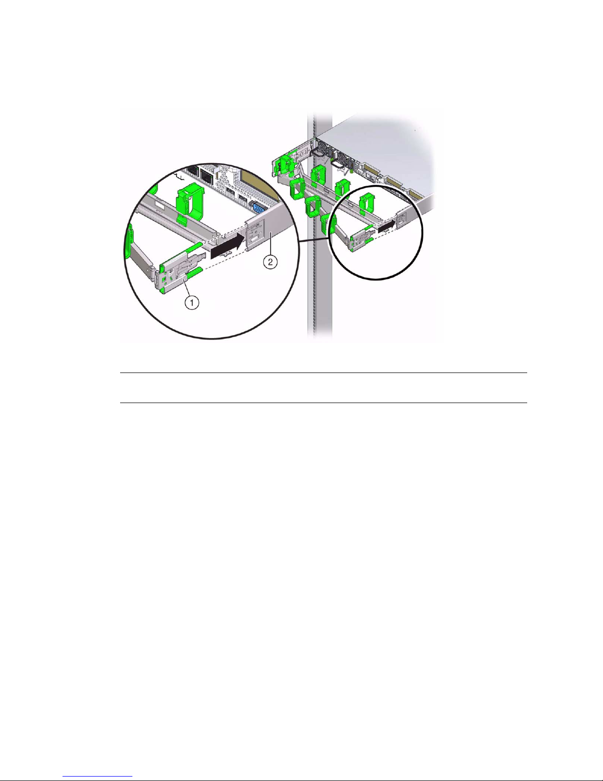
FIGURE: Inserting the CMA Slide-Rail Connector Into the Back of the Right Slide-Rail
Figure Legend
1 CMA slide-rail connector
2 Right slide-rail
6. Insert the left CMA slide-rail connector into the back of the left slide-rail
assembly until the connector locks into place with an audible click.
52 Sun Server X3-2 Installation Guide • April 2014
Page 65
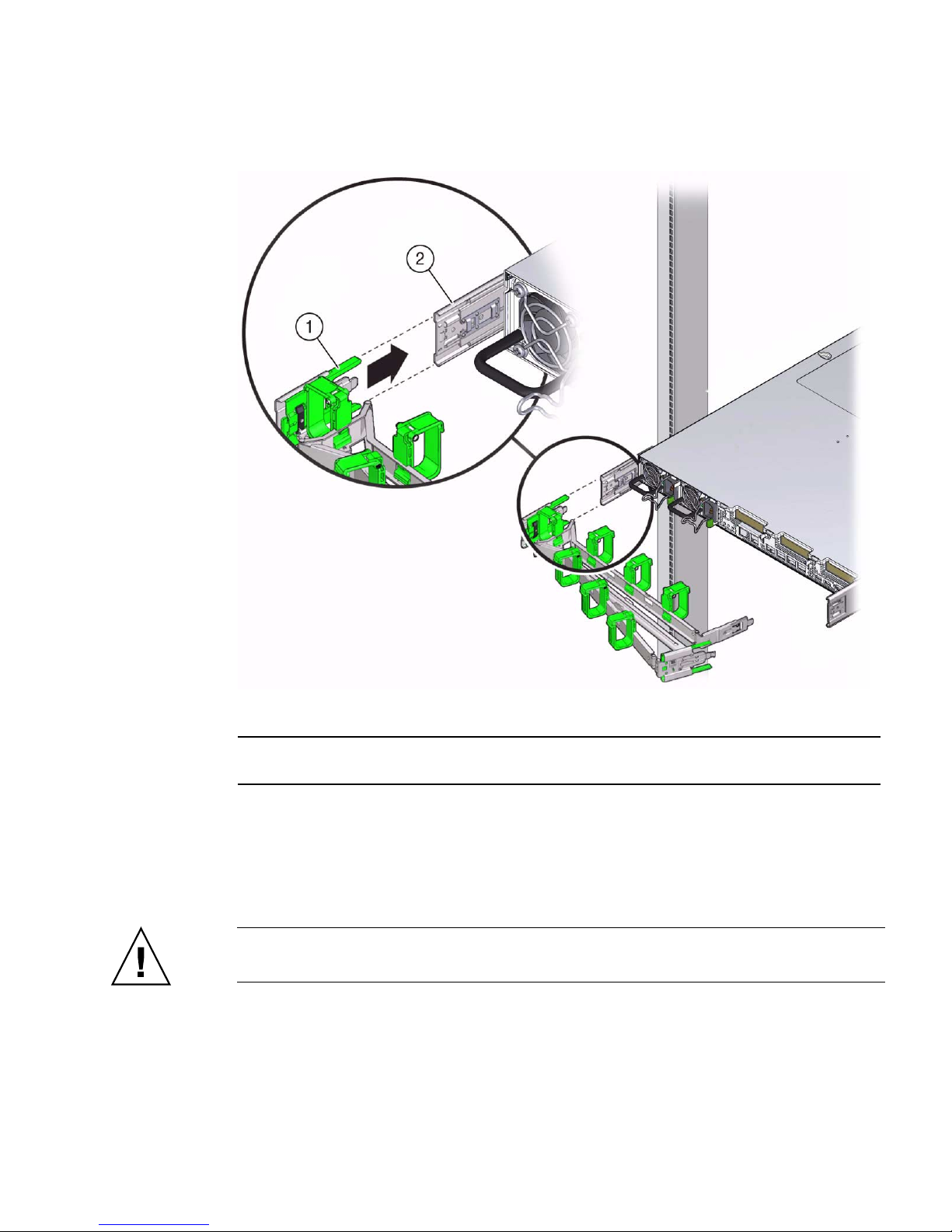
FIGURE: Inserting the CMA Slide-Rail Connector Into the Back of the Left Slide-Rail
Figure Legend
1 CMA slide-rail connector
2 Left slide-rail
7. To verify that the slide rails and the CMA are operating properly before routing
cables through the CMA, perform the following steps.
a. To prevent the rack from tipping forward when the server is extended, extend
all rack anti-tilt devices.
Caution – To reduce the risk of personal injury, stabilize the rack cabinet and extend
all anti-tilt devices before extending the server from the rack.
For instructions for stabilizing the rack, see “Stabilize the Rack for Installation”
on page 25.
b. Slowly pull the server out of the rack until the slide-rails reach their stops.
Installing the Server Into a Rack 53
Page 66
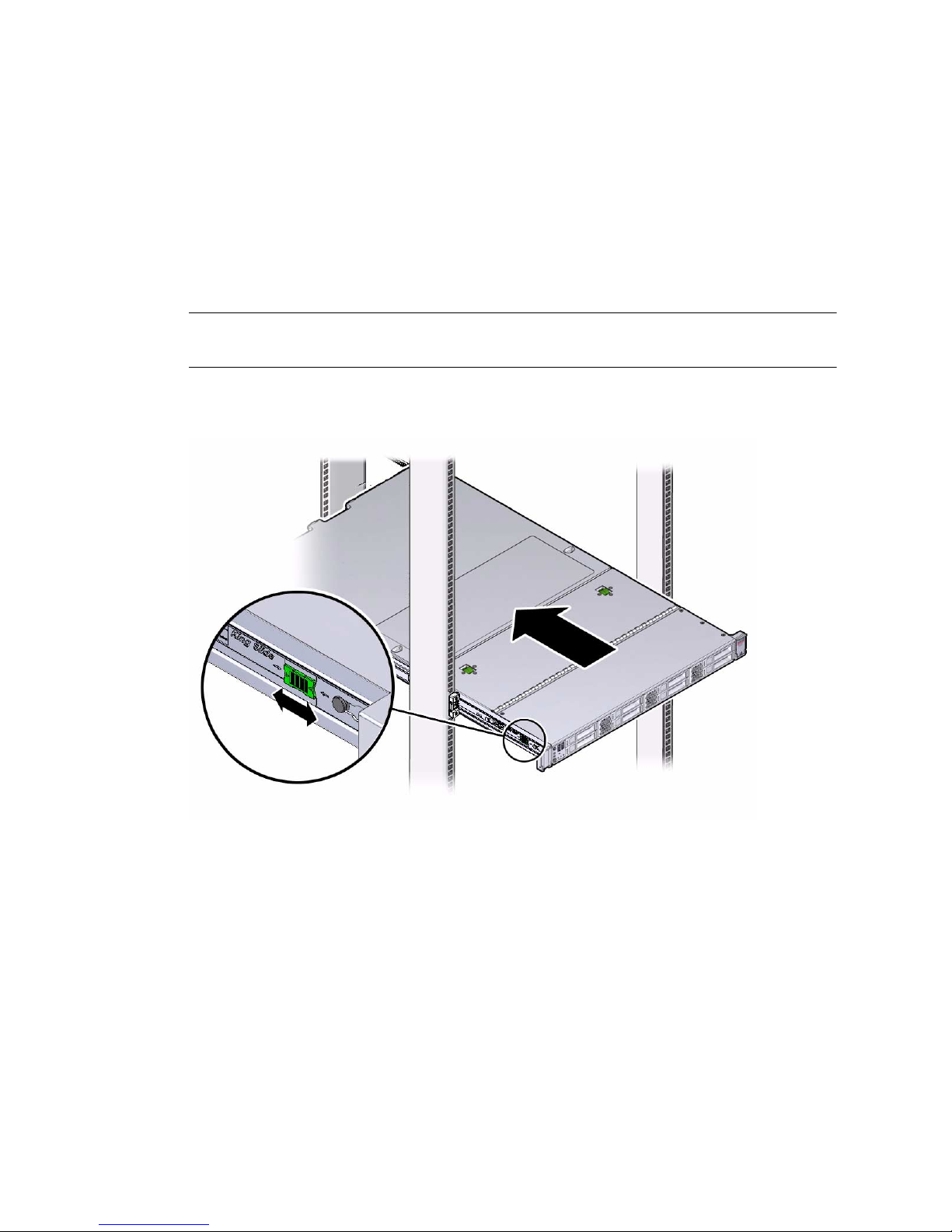
c. Verify that the CMA extends fully with the slide-rails.
8. To return the server to the rack, perform the following steps.
a. Simultaneously pull and hold the two green release tabs (one on each side of
of the server) toward the front of the server (see the following figure) while
you push the server into the rack. As you push the server into the rack, verify
that the CMA retracts without binding.
Note – To pull the green release tab, place your finger in the center of the tab, not on
the end, and apply pressure as you pull the tab toward the front of the server.
FIGURE: Location of Slide-Rail Release Tabs
b. Continue pushing the server into the rack until the slide-rail locks (on the
front of the server) engage the slide-rail assemblies.
You will hear an audible click when the server is in the normal rack position.
9. Install and route cables to your server, as required.
Instructions for installing the server cables are provided in “Cabling the Server”
on page 57.
54 Sun Server X3-2 Installation Guide • April 2014
Page 67
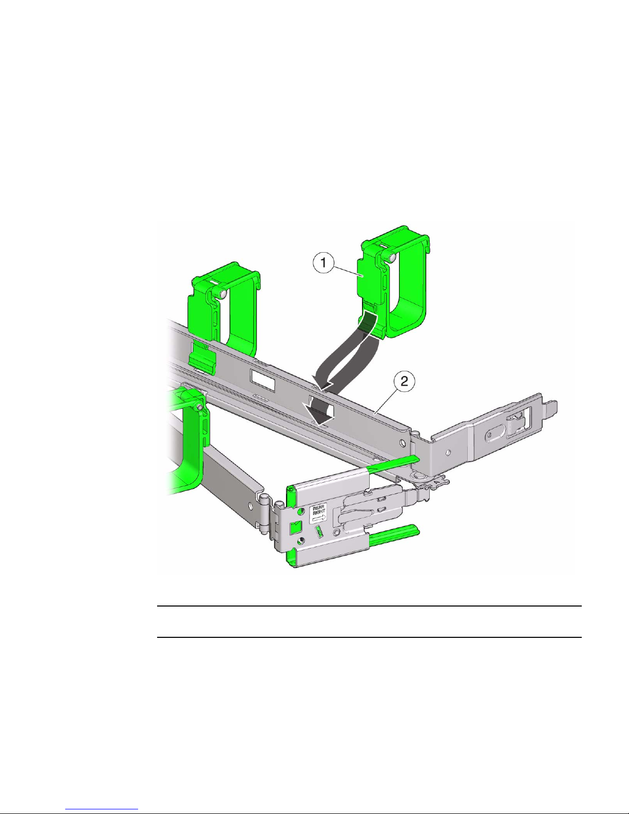
10. If required, attach the cable hooks and loop straps to the CMA, and press them
into place to secure the cables.
Cable hooks and loops are preinstalled on the CMA. Perform this step if you need
to reinstall cable hooks and straps on the CMA.
For best results, place three cable straps, evenly spaced, on the rear-facing side of
the CMA and three cable straps on the side of the CMA nearest the server.
FIGURE: Installing the CMA Cable Straps
Figure Legend
1 CMA cable strap
2 CMA arm
Installing the Server Into a Rack 55
Page 68

56 Sun Server X3-2 Installation Guide • April 2014
Page 69

Cabling the Server
This section contains procedures for connecting data and server management cables
and power cords to the server.
Description Links
Review connector port locations. “Rear Cable Connections and Ports” on
page 57
Learn about server Ethernet ports. “Ethernet Ports” on page 59
Cable the server. “Attaching Data Cables and Power Cords to
the Server” on page 60
Related Information
■ “Installation Procedure Overview” on page 2
■ “Install the Second-Generation Cable Management Arm” on page 35
■ “Install the First-Generation Cable Management Arm” on page 50
■ “Setting Up Software and Firmware Using Oracle System Assistant” on page 83
■ “Connecting to Oracle ILOM” on page 63
Rear Cable Connections and Ports
The following figure shows the locations of cable connectors and ports on the back of
the Sun Server X3-2 and the cables and devices that you would typically connect to
them.
57
Page 70
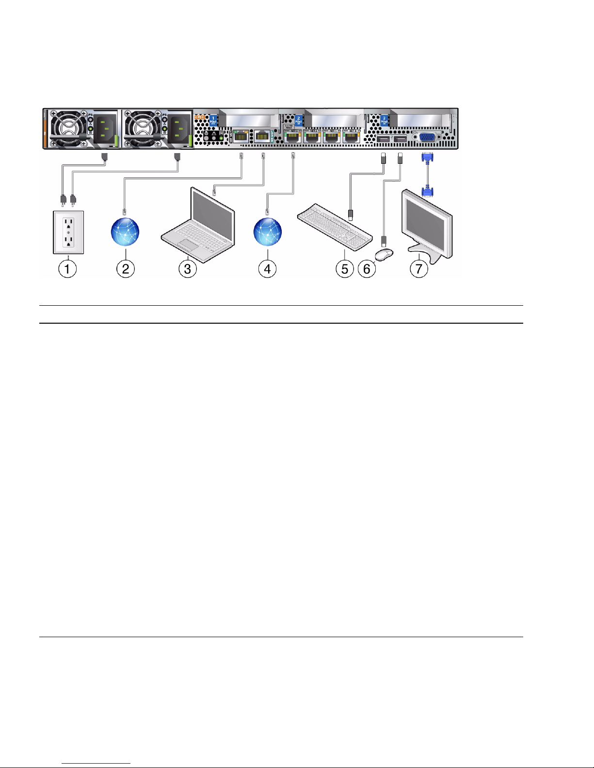
FIGURE: Rear Panel Cabling Reference
No. Cable Port or Expansion Slot Description
1 Power supply 0 input power
Power supply 1 input power
The server has two power supply connectors, one for each
power supply.
Do not attach power cables to any installed power supplies
until you have finished connecting the data cables and have
connected the server to a serial terminal or a terminal
emulator (PC or workstation). The server goes into standby
power mode and the Oracle ILOM service processor initializes
when the AC power cables are connected to the power source.
System messages might be lost after 60 seconds if the server is
not connected to a terminal, PC, or workstation.
Note - Oracle ILOM will signal a fault on any installed power
supply that is not connected to an AC power source, since it
might indicate a loss of redundancy.
2 Network management port (NET MGT) The service processor NET MGT port is the optional
connection to the Oracle ILOM service processor. The NET
MGT port is configured by default to use Dynamic Host
Configuration Protocol (DHCP). The service processor NET
MGT port uses an RJ-45 cable for a 10/100BASE-T connection.
3 Serial management port (SER MGT) The service processor SER MGT port uses an RJ-45 cable and
is the default connection to the Oracle ILOM service processor.
This port supports local connections to the server and only
recognizes Oracle ILOM command-line interface (CLI)
commands. Typically you connect a terminal or a terminal
emulator to this port.
Note - This port does not support network connections.
58 Sun Server X3-2 Installation Guide • April 2014
Page 71

No. Cable Port or Expansion Slot Description
4 Ethernet ports (NET 3, NET 2, NET 1,
NET 0)
5, 6 USB ports (USB 0, USB 1) The two USB ports support hot-plugging. You can connect
7 Video port (VGA, DB-15) Use a 15-pin video cable to connect a VGA video device to the
The four 10-Gigabit Ethernet ports enable you to connect the
system to the network. See “Ethernet Ports” on page 59 for
more information.
Note - Ethernet ports NET 2 and NET 3 are nonfunctional in
single-processor systems.
and disconnect USB cables and peripheral devices while the
server is running, without affecting system operations.
server. Optionally, you can connect to the VGA port when
installing the operating system.
Related Information
■ “Ethernet Ports” on page 59
■ “Attaching Data Cables and Power Cords to the Server” on page 60
Ethernet Ports
The server has four RJ-45, 10-Gigabit Ethernet (10GbE) network connectors, labeled
NET3, NET2, NET1, and NET0 from left to right on the server rear panel. Use these
ports to connect the server to the network.
Note – Ethernet ports NET 2 and NET 3 are nonfunctional in single-processor
systems.
The LEDs located above each NET port are Link/Activity (left) and Speed (right)
indicators for each port. The following table lists the Ethernet transfer rates and the
Speed LED color.
Connection Type IEEE Terminology Speed LED Color Transfer Rate
Fast Ethernet 100BASE-T Off 100 Mbits/sec
Gigabit Ethernet 1000BASE-T Amber 1,000 Mbits/sec
10 Gigabit Ethernet 10GBASE-T Green 10,000 Mbits/sec
Cabling the Server 59
Page 72

Related Information
■ “Rear Cable Connections and Ports” on page 57
■ “Attaching Data Cables and Power Cords to the Server” on page 60
Attaching Data Cables and Power Cords
to the Server
This section describes how to connect data and power cables to the server and how
to apply power to the server for the first time.
■ “Connect the Data Cables” on page 60
■ “Connect the Power Cords” on page 61
Related Information
■ “Rear Cable Connections and Ports” on page 57
■ “Ethernet Ports” on page 59
▼ Connect the Data Cables
To locate the server cable connections, see FIGURE: Rear Panel Cabling Reference on
page 58.
1. (Recommended method) To cable the server for local connection to Oracle
System Assistant:
a. Connect a VGA monitor to the VGA port on the server.
b. Connect a USB keyboard and mouse to the USB connectors on the server.
2. (Alternative Method) To cable the server for connection to Oracle ILOM:
■ For a local serial connection– Connect a serial cable between the server ’s serial
management port (SER MGT) and a terminal device.
This connection provides initial communication with the SP. Set the server to
communicate using 9600 baud, 8 bit, no parity, 1 stop bit. For DTE-to-DTE
communication, use the supplied RJ-45 crossover adapter with a standard RJ-45
cable to set up a null modem connection (transmit and receive signals crossed
over).
60 Sun Server X3-2 Installation Guide • April 2014
Page 73

■ For a remote Ethernet connection– Connect an Ethernet cable between the
server’s network management port (NET MGT) and the network to which
future connections to the SP and host will be made.
If using Oracle ILOM, configure the system for the first time through the SER
MGT port. After initial configuration, you can set up communication between
the SP and host through the remote Ethernet interface.
3. For network access, connect an Ethernet cable between the server’s NET ports
(NET3-0) and the network to which the server will communicate.
▼ Connect the Power Cords
1. For each installed power supply, connect one grounded server power cord to a
grounded electrical outlet.
2. Connect the server power cords to the power supply AC connectors on the back
panel of the server and use the Velcro strap to secure them.
When the power cords are connected to the system, the power supply LEDs light
and the SP OK LED will blink rapidly while the service processor (SP) is booting.
The SP OK LED will be illuminated solid green once the service processor has
successfully booted. After the service processor has booted, the Power/OK LED
on the front panel will blink slowly, indicating the host is in standby power mode.
In standby power mode, the server is not yet initialized or powered on.
Cabling the Server 61
Page 74
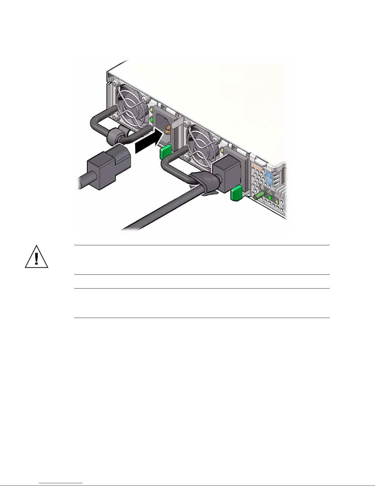
Caution – Do not operate the server unless all fans, component heatsinks, air
baffles, and the top cover are installed. Damage to server components can occur if the
server is operated without adequate cooling mechanisms.
Note – Do not apply main power to the rest of the server until you are ready to
configure a preinstalled operating system or perform a fresh install of an operating
system. At this point, power is supplied only to the SP and the power supply fans.
62 Sun Server X3-2 Installation Guide • April 2014
Page 75

Connecting to Oracle ILOM
Oracle Integrated Lights Out Manager (ILOM) is embedded on firmware in the Sun
Server X3-2. The server supports Oracle ILOM version 3.1. Oracle ILOM provides the
following functionality:
■ A Remote Console function that enables you to connect to the Oracle System
Assistant and set up your server remotely.
■ Extensive management and monitoring capabilities for the server.
For complete information about Oracle ILOM, refer to the Oracle Integrated Lights
Out Manager (ILOM) 3.1 Documentation Library at
http://www.oracle.com/pls/topic/lookup?ctx=ilom31.
This section describes how to access and get started using Oracle ILOM for your
server.
Description Links
Learn about Oracle ILOM hardware and
interfaces.
Learn about network ports. “Network Defaults” on page 64
Log in directly to Oracle ILOM using a
terminal connected to the serial port.
Log in to Oracle ILOM over the network
using an Ethernet connection.
Access the host console through Oracle
ILOM.
Troubleshoot the service processor
connection.
“Oracle ILOM Hardware and Interfaces” on
page 64
“Log In to Oracle ILOM Using a Local Serial
Connection” on page 66
“Logging In to Oracle ILOM Using a Remote
Ethernet Connection” on page 66
“Accessing the Host Console Through Oracle
ILOM” on page 75
“Troubleshooting the Service Processor
Connection” on page 79
Related Information
■ “Installation Procedure Overview” on page 2
■ “Attaching Data Cables and Power Cords to the Server” on page 60
■ Oracle Integrated Lights Out Manager (ILOM) 3.1 Documentation Library at
http://www.oracle.com/pls/topic/lookup?ctx=ilom31
63
Page 76

Oracle ILOM Hardware and Interfaces
The following table lists the components and functions of Oracle ILOM. For complete
information about Oracle ILOM, refer to the Oracle Integrated Lights Out Manager
(ILOM) 3.1 Documentation Library at
http://www.oracle.com/pls/topic/lookup?ctx=ilom31.
Component Function
Hardware • Embedded service processor (SP) chipset that monitors the status and configuration of
components such as fans, storage drives, and power supplies.
• Two rear panel external connections: NET MGT port Ethernet connection and SER
MGT RJ-45 serial management port.
Interfaces • Web browser interface
• SSH command-line interface (CLI)
• IPMI v2.0 CLI
• SNMP v3 interface
With Oracle ILOM, you can monitor and manage the server components. Oracle
ILOM lets you perform the following tasks:
■ Configure network information
■ View and edit hardware configurations for the SP
■ Monitor vital system information and view logged events
■ Manage Oracle ILOM user accounts
Related Information
■ Oracle Integrated Lights Out Manager (ILOM) 3.1 Documentation Library at
http://www.oracle.com/pls/topic/lookup?ctx=ilom31
Network Defaults
The Sun Server X3-2 supports dual-stack IPv4 and IPv6 settings, which enable Oracle
ILOM to fully operate in an IPv4 and IPv6 network environment. For IPv4
configurations, DHCP is enabled by default, allowing a DHCP server on the network
to automatically assign network settings to the server. For IPv6 configurations, IPv6
64 Sun Server X3-2 Installation Guide • April 2014
Page 77

stateless auto-configuration is enabled by default, allowing an IPv6 router on the
network to assign the network settings. In a typical configuration, you will accept
these settings assigned by the DHCP server or IPv6 router.
Note – To determine the IP address or host name assigned by the DHCP server, use
the network tools provided with the DHCP server or IPv6 router.
The following procedures enable you to test that the assigned settings are working
correctly and to establish a connection to Oracle ILOM locally and remotely.
■ To log in locally, see “Log In to Oracle ILOM Using a Local Serial Connection” on
page 66.
■ To log in remotely, use the IP address, host name, or IPv6 local link name assigned
to the server SP and follow the instructions in “Log In to Oracle ILOM Remotely
Using the Command-Line Interface” on page 69.
Logging In to Oracle ILOM Using a Local
Serial Connection
To log in to Oracle ILOM locally using a serial connection, you need to connect a
serial null modem cable to the RJ-45 serial port labeled SER MGT and to a terminal
or terminal emulator. Ensure that the following serial communication settings are
configured:
■ 8N1: eight data bits, no parity, one stop bit
■ 9600 baud
■ Disable hardware flow control (CTS/RTS)
■ Disable software flow control (XON/XOFF)
This section includes the following procedure:
■ “Log In to Oracle ILOM Using a Local Serial Connection” on page 66
Related Information
■ “Logging In to Oracle ILOM Using a Remote Ethernet Connection” on page 66
Connecting to Oracle ILOM 65
Page 78

▼ Log In to Oracle ILOM Using a Local Serial
Connection
This procedure does not require that you know the IP address of the sever SP. It does
require that you have an Oracle ILOM Administrator account. You must be present at
the server to perform this procedure.
1. To ensure that your server has the necessary connections for local access to
Oracle ILOM, follow the instructions in “Attaching Data Cables and Power
Cords to the Server” on page 60.
2. To establish a connection between your serial console and Oracle ILOM, press
Enter on the terminal.
A login prompt to Oracle ILOM appears.
3. Log in to the Oracle ILOM command-line interface (CLI) using an
Administrator account.
Note – To enable first-time login and access to Oracle ILOM, a default Administrator
account and its password are provided with the system. To build a secure
environment, you must change the default password (changeme) for the default
Administrator account (root) after your initial login to Oracle ILOM. If this default
Administrator account has since been changed, contact your system administrator for
an Oracle ILOM user account with Administrator privileges.
Oracle ILOM displays a default command prompt (->), indicating that you have
successfully logged in to Oracle ILOM.
Related Information
■ “Log In to Oracle ILOM Remotely Using the Web Interface” on page 67
■ “Log In to Oracle ILOM Remotely Using the Command-Line Interface” on page 69
Logging In to Oracle ILOM Using a
Remote Ethernet Connection
To log in to Oracle ILOM remotely using either the command-line interface (CLI) or
the web interface, you must know the IP address of the server SP. The following
sections describe how you can determine the IP address (if you do not know it), how
to log in to Oracle ILOM, and how to view and modify the SP IP address:
66 Sun Server X3-2 Installation Guide • April 2014
Page 79

■ “Determining the IP Address of the Server SP” on page 67
■ “Log In to Oracle ILOM Remotely Using the Web Interface” on page 67
■ “Log In to Oracle ILOM Remotely Using the Command-Line Interface” on page 69
■ “View or Modify an SP IPv4 Address” on page 70
■ “View or Modify an SP IPv6 Address” on page 73
Determining the IP Address of the Server SP
If a DHCP server or IPv6 router cannot be reached after ten seconds, the SP requests
will timeout. After the timeout, the SP then only periodically checks for a DHCP
server or IPv6 router.
If you do not have a DHCP server or IPv6 router on your network, or you need to
view or assign an IP address to the SP, follow the procedures in these sections:
■ “View or Modify an SP IPv4 Address” on page 70
■ “View or Modify an SP IPv6 Address” on page 73
▼ Log In to Oracle ILOM Remotely Using the Web
Interface
This procedure requires that you have an Oracle ILOM Administrator account and
that you know the IP address or host name of the server SP.
To improve response times, disable the web browser proxy server (if used).
1. To ensure that your server has the necessary connections for remote access to
Oracle ILOM, follow the instructions in “Attaching Data Cables and Power
Cords to the Server” on page 60.
2. Type the IP address of the server’s SP into your web browser address field.
For example: https://198.51.100.26
The Oracle ILOM web interface login page appears.
Connecting to Oracle ILOM 67
Page 80
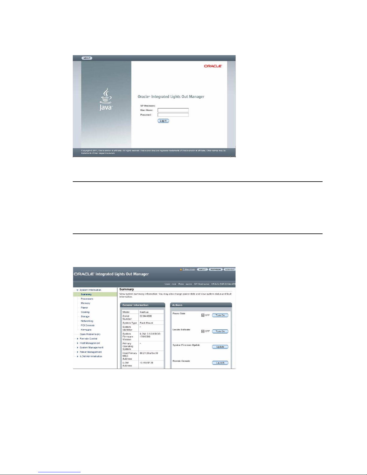
3. Type your user name and password.
Note – To enable first-time login and access to Oracle ILOM, a default Administrator
account and its password are provided with the system. To build a secure
environment, you must change the default password (changeme) for the default
Administrator account (root) after your initial login to Oracle ILOM. If this default
Administrator account has since been changed, contact your system administrator for
an Oracle ILOM user account with Administrator privileges.
4. Click Log In.
The System Information Summary page appears.
You are now logged in to the server’s Oracle ILOM. For information about using
Oracle ILOM, refer to the Oracle Integrated Lights Out Manager (ILOM) 3.1
Documentation Library at
http://www.oracle.com/pls/topic/lookup?ctx=ilom31.
68 Sun Server X3-2 Installation Guide • April 2014
Page 81

Related Information
■ “Logging In to Oracle ILOM Using a Local Serial Connection” on page 65
■ “View or Modify an SP IPv4 Address” on page 70
■ “View or Modify an SP IPv6 Address” on page 73
▼ Log In to Oracle ILOM Remotely Using the
Command-Line Interface
This procedure requires that you have an ILOM Administrator account and that you
know the IP address or host name of the server SP.
1. To ensure that your server has the necessary connections for remote access to
Oracle ILOM, follow the instructions in “Attaching Data Cables and Power
Cords to the Server” on page 60.
2. Using a Secure Shell (SSH) session, log in to Oracle ILOM by specifying your
Administrator account user name and the IP address or host name of the server
SP.
Note – To enable first-time login and access to Oracle ILOM, a default Administrator
account and its password are provided with the system. To build a secure
environment, you must change the default password (changeme) for the default
Administrator account (root) after your initial login to Oracle ILOM. If this default
Administrator account has since been changed, contact your system administrator for
an Oracle ILOM user account with Administrator privileges.
The login command syntax can be either of the following:
ssh -l username host
or
ssh username@host
Where host is either the IP address or the host name of the server SP (when using
DNS).
For example:
The Oracle ILOM password prompt appears.
Connecting to Oracle ILOM 69
Page 82

3. Type a password for the Administrator account.
For example:
[email protected]’s password: changeme
Oracle ILOM displays a default command prompt (->), indicating that you have
successfully logged in to Oracle ILOM. For information about using Oracle ILOM,
refer to the Oracle Integrated Lights Out Manager (ILOM) 3.1 Documentation
Library at http://www.oracle.com/pls/topic/lookup?ctx=ilom31.
Related Information
■ “Logging In to Oracle ILOM Using a Local Serial Connection” on page 65
■ “View or Modify an SP IPv4 Address” on page 70
■ “View or Modify an SP IPv6 Address” on page 73
▼ View or Modify an SP IPv4 Address
To view or modify the IPv4 address currently assigned to the Oracle ILOM SP:
Note – You can also change network settings using the BIOS Setup Utility. For
information about the BIOS Setup Utility, refer to the Sun Server X3-2 Administration
Guide, “Setting Up BIOS Configuration Parameters” on page 107.
1. Log in to Oracle ILOM using one of the following procedures:
■ “Log In to Oracle ILOM Using a Local Serial Connection” on page 66
■ “Log In to Oracle ILOM Remotely Using the Command-Line Interface” on
page 69
Note – If you log in to Oracle ILOM using an Ethernet connection, after you modify
the network settings, your connection will be terminated, and you will have to log in
again using the new settings.
2. To navigate to the /SP/network target, use the cd command:
-> cd /SP/network
3. Do one of the following:
■ If you have a DHCP server on the network, to view the settings assigned to the
server by the DHCP server, type the following command:
-> show /SP/network
70 Sun Server X3-2 Installation Guide • April 2014
Page 83

■ If there is no DHCP server, or if you want to assign settings, use the set
command to assign values for the properties listed in the table in Step 4. For
example:
-> set /SP/network pendingipdiscovery=static
-> set /SP/network pendingipaddress=198.51.100.26
-> set /SP/network pendingipnetmask=10.255.255.255
-> set /SP/network pendingipgateway=198.51.100.27
-> set /SP/network commitpending=true
Note – If you are logged in to Oracle ILOM using an Ethernet connection, when you
set commitpending to true to commit the changes to the network settings, your
Oracle ILOM connection will be terminated and you will have to log in again using
the new settings.
4. If you want to enable sideband management, type the following commands:
-> set /SP/network pendingmanagementport=NETn
Where n equals 0, 1, 2, or 3.
Note – Ethernet ports NET2 and NET3 are nonfunctional in single-processor systems
and, therefore, cannot be used for sideband management.
-> set /SP/network commitpending=true
The following table describes the network settings.
Connecting to Oracle ILOM 71
Page 84

Property and Set Property Value Set Property Value Description
state set state=enabled The network state is
enabled by default.
pendingipdiscovery set pendingipdiscovery=static To enable a static network
configuration, set
pendingipdiscovery to
static.
By default,
pendingipdiscovery is
set to dhcp.
pendingmanagementport set pendingmanagementport=NET0 By default,
pendingmanagementpor
t is set to the NET MGT
port (MGMT).
To enable sideband
management, set
pendingmanagementpor
t to an available 10-Gigabit
Ethernet port. Set
pendingmanagementpor
t to NETn, where n
represents 3, 2, 1, or 0.
Note - Ethernet ports NET2
and NET3 are
nonfunctional in
single-processor systems
and, therefore, cannot be
used for sideband
management.
pendingipaddress
pendingipnetmask
pendingipgateway
Related Information
■ “Determining the IP Address of the Server SP” on page 67
■ “View or Modify an SP IPv6 Address” on page 73
72 Sun Server X3-2 Installation Guide • April 2014
set pendingipaddress=<ip_address>
set pendingipnetmask=<netmask>
set pendingipgateway=<gateway>
To assign multiple static
network settings, type the
set command followed by
the pending command for
each property value (IP
address, netmask, and
gateway), and then type
the static value that you
want to assign.
Page 85

▼ View or Modify an SP IPv6 Address
To view or modify the IPv6 address currently assigned to the Oracle ILOM SP:
Note – You can also change network settings using the BIOS Setup Utility. For
information about the BIOS Setup Utility, refer to the Sun Server X3-2 Administration
Guide, “Setting Up BIOS Configuration Parameters” on page 107.
1. Log in to Oracle ILOM using one of the following procedures:
■ “Log In to Oracle ILOM Using a Local Serial Connection” on page 66
■ “Log In to Oracle ILOM Remotely Using the Command-Line Interface” on
page 69
Note – If you log in to Oracle ILOM using an Ethernet connection, after you modify
the network settings, your connection will be terminated, and you will have to log in
again using the new settings.
2. To navigate to the /SP/network/ipv6 target, use the cd command:
-> cd /SP/network/ipv6.
3. To view the IPv6 network settings configured on the device, type the show
command.
For example, see the following sample output values for the IPv6 properties on a
server SP device.
-> show
/SP/network/ipv6
Targets:
Properties:
state = enabled
autoconfig = stateless
dhcpv6_server_duid = (none)
link_local_ipaddress = 2001:DB8:n:n
static_ipaddress = ::/128
ipgateway = 2001:DB8:n:n
pending_static_ipaddress = ::/128
dynamic_ipaddress_1 = 2001:DB8:n:n
Commands:
cd
show
set
Connecting to Oracle ILOM 73
Page 86

4. To configure an IPv6 auto-configuration option, use the set command to specify
the following auto-configuration property values:
Property Set Property Value Description
state set state=enabled The IPv6 network state is enabled by
default. To enable an IPv6
auto-configuration option, set this state to
enabled.
autoconfig set autoconfig=<value> Specify this command followed by the
autoconfig value you want to set.
Options include:
• stateless (default setting)
Automatically assigns IP address learned
from IPv6 network router.
• dhcpv6_stateless
Automatically assigns DNS information
learned from the DHCPv6 server.
• dhcpv6_stateful
Automatically assigns the IPv6 address
learned from the DHCPv6 server.
• disabled
Disables all auto-configuration property
values and sets the read-only property
value for Link Local address.
Note – The IPv6 configuration options listed in the above table take effect after they
are set, that is, you do not need to commit these changes under the /network target.
Note – You can enable the stateless auto-configuration option to run at the same
time the option for dhcpv6_stateless is enabled or the option for
dhcpv6_stateful is enabled. However, the auto-configuration options for
dhcpv6_stateless and dhcpv6_stateful should not be enabled to run at the
same time.
5. To set a static IPv6 address, specify the following property types:
74 Sun Server X3-2 Installation Guide • April 2014
Page 87

Property and Set Property Value Set Property Value Description
state set state=enabled The IPv6 network state is enabled
by default. To enable a static IP
address set this state to enabled.
pending_static_ipaddress set
pending_static_ipaddress=
n:n:n:n:n:n:n:n/<subnet mask
length_in_bits>
commitpending set commitpending=true Type set commitpending=true
Type this command followed by the
property value for the static IPv6
address and subnet netmask that
you want to assign to the device.
IPv6 address example:
2001:DB8:n:n
to commit changes.
Note – Assigning a new static IP address to the device will end all active Oracle
ILOM sessions to the device. To log in again to Oracle ILOM, you will need to create
a new session using the newly assigned IP address.
Related Information
■ “Determining the IP Address of the Server SP” on page 67
■ “View or Modify an SP IPv4 Address” on page 70
Accessing the Host Console Through
Oracle ILOM
Connecting to the host console through Oracle ILOM enables you to perform actions
as if you were at the host. This can be useful when you need remote access to the
server’s BIOS Setup Utility, when you configure or install an operating system or
other software on the server, or when you want to access Oracle System Assistant
through Oracle ILOM.
For more instructions, see the following sections:
■ “Set Mouse Mode” on page 76
■ “Connect to the Host Console Using the Oracle ILOM Web Interface” on page 76
■ “Connect to the Host Serial Console Using the Oracle ILOM Command-Line
Interface” on page 79
Connecting to Oracle ILOM 75
Page 88

▼ Set Mouse Mode
The mouse mode setting in Oracle ILOM must be set according to the requirements
of the operating system that you are using to connect to the host console, either
Absolute or Relative; otherwise, the on-screen mouse pointer will not track the
mouse movements.
■ For Windows and Oracle Solaris operating systems, set the mouse mode to
Absolute.
■ For newer versions of Linux operating systems, Oracle Linux 6.x, Red Hat
Enterprise Linux (RHEL) 6.x, and SUSE Linux Enterprise Server (SLES) 11 or later,
set the mouse mode to Absolute.
■ For older versions of Linux operating systems, Oracle Linux 5.x, RHEL 5.x, and
SLES 10, set the mouse mode to Relative and switch to Absolute if the mouse does
not work properly.
■ For Oracle VM and VMware ESXi, mouse mode settings do not apply.
To set the mouse mode, perform the following steps:
1. Log in to the Oracle ILOM web interface.
2. Select Remote Control > Mouse Mode and select the appropriate mode
according to the operating system that you are using to connect to the host
console.
Note – Some versions of Oracle ILOM require the service processor (SP) to be reset
before the change will take effect. You will be prompted by an Oracle ILOM message
if your SP needs to be reset.
▼ Connect to the Host Console Using the Oracle
ILOM Web Interface
To connect to the host console from a remote system, your remote system must meet
the following requirements:
■ An operating system such as Oracle Solaris, Linux, Oracle VM, or Windows is
installed and the mouse mode is set correctly (see “Set Mouse Mode” on page 76).
■ The system must be connected to a network that has access to one of the Ethernet
management ports.
■ Java Runtime Environment (JRE) 1.5 or later is installed. For CD-ROM redirection,
32-bit Java must be used.
76 Sun Server X3-2 Installation Guide • April 2014
Page 89
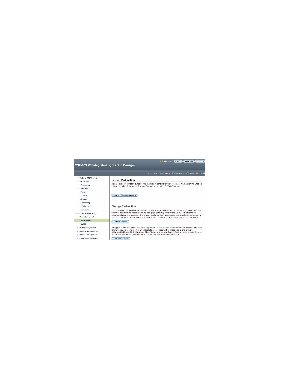
■ If the Remote Console system is running the Oracle Solaris 10 operating system,
volume management must be disabled for the Remote Console to access the
physical floppy and CD/DVD-ROM drives.
■ If the Remote Console system is running Windows, Internet Explorer Enhanced
Security must be disabled.
■ The Remote Console system and Oracle ILOM service processor are set up
according to the instructions in the Oracle Integrated Lights Out Manager (ILOM)
3.1 Documentation Library at
http://www.oracle.com/pls/topic/lookup?ctx=ilom31.
1. Log in to the server’s Oracle ILOM using an account with Administrator
privileges.
See “Log In to Oracle ILOM Remotely Using the Web Interface” on page 67.
2. In the System Information menu, expand the Remote Control tab in the menu
tree and click Redirection.
The Launch Redirection page appears.
3. In the Launch Redirection page, click Launch Remote Console.
Note the following:
■ When you are using a Windows system for Remote Console redirection, a
Hostname Mismatch warning dialog box might appear after you click Launch
Remote Console. If it does, click the Yes button to clear it.
Connecting to Oracle ILOM 77
Page 90
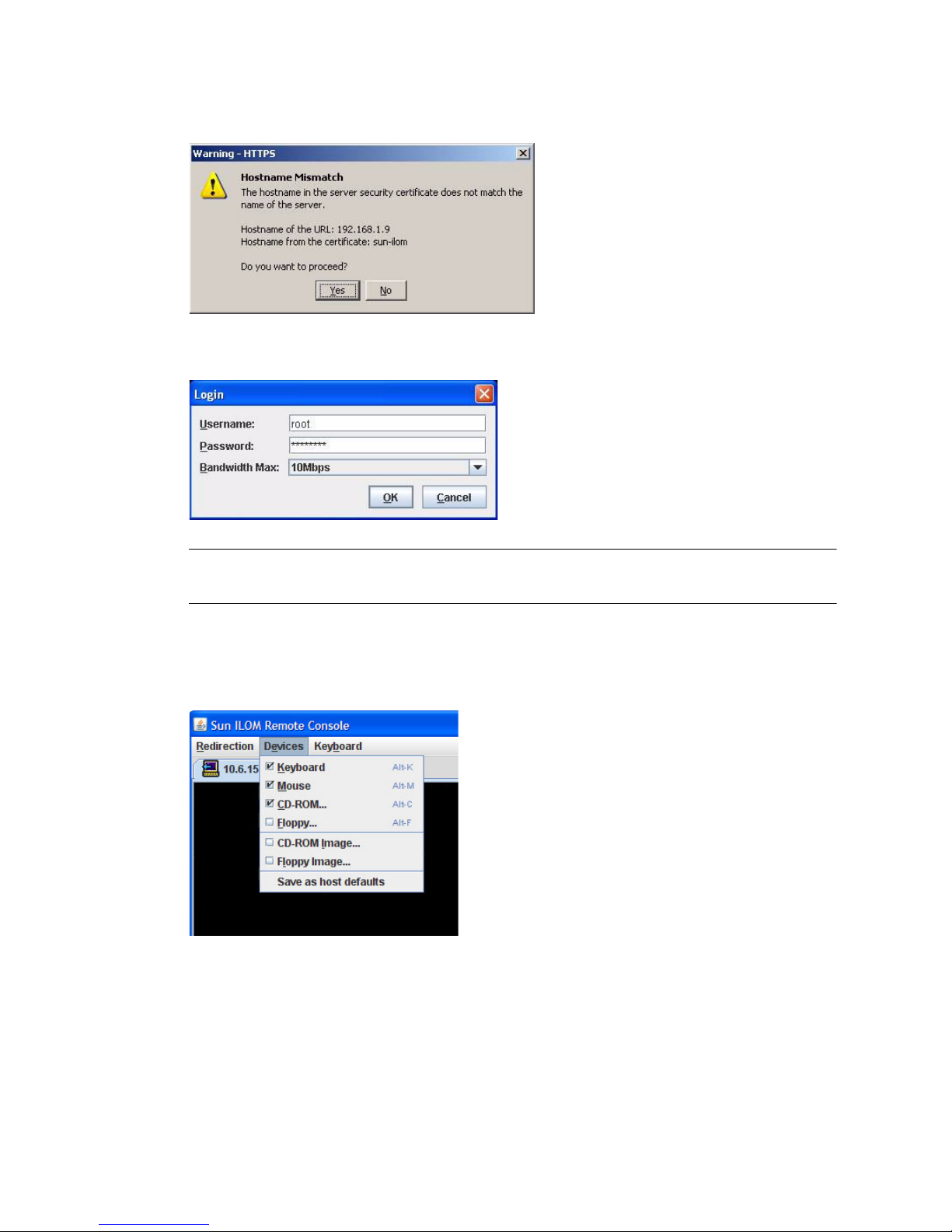
■ A Remote Control login dialog box might appear. If it does, reenter your user
name and password, and click OK.
Note – The Login dialog box should not appear unless Single Sign-On is either
disabled or not supported.
The Oracle ILOM Remote System Console screen appears.
4. To redirect one or more devices on your remote system to the host console,
select the appropriate items from the Devices menu.
■ Remote Physical Floppy Disk – Select Floppy to redirect the server to the
physical floppy drive attached to the remote system.
■ Remote Physical CD/DVD – Select CD-ROM to redirect the server to the
CD/DVD in the CD/DVD drive attached to the remote system.
■ Remote CD/DVD Image – Select CD-ROM Image to redirect the server to the
ISO image file located on the remote system.
78 Sun Server X3-2 Installation Guide • April 2014
Page 91

Note – Using either of the CD/DVD options to install software on your server might
significantly increase the time necessary to perform the installation because the
content is accessed over the network. The installation duration depends on the
network connectivity and traffic.
▼ Connect to the Host Serial Console Using the
Oracle ILOM Command-Line Interface
1. Log in to the server’s Oracle ILOM using an account with Administrator
privileges.
Use one of the following methods:
■ Use the serial management port as described in “Log In to Oracle ILOM Using
a Local Serial Connection” on page 66.
■ Use a client system to establish an SSH session over the network as described in
“Log In to Oracle ILOM Remotely Using the Command-Line Interface” on
page 69.
2. To access the host serial console, type the command:
-> start /HOST/console
The serial console output appears on the screen.
Note – If the serial console is in use, stop and restart it using the stop
/HOST/console command followed by the start /HOST/console command.
3. To return to the Oracle ILOM console, press Esc followed by the “(“ character
(Shift-9).
Troubleshooting the Service Processor
Connection
This section addresses two issues that might occur regarding the Oracle ILOM
service processor (SP):
■ The Oracle ILOM SP is hung and needs to be reset.
Connecting to Oracle ILOM 79
Page 92

■ As the system administrator, you have forgotten the root account password and
you need to recover it.
For instructions on how to handle each of these problems, see the following sections:
■ “Reset the Service Processor Using Oracle ILOM” on page 80
■ “Reset the Service Processor From the Server Back Panel” on page 80
■ “Recover Root Account Password” on page 81
▼ Reset the Service Processor Using Oracle ILOM
● If the Oracle ILOM service processor (SP) is hung, use one of the following
methods to reset it:
■ From the Oracle ILOM command-line interface (CLI), type: reset /SP.
■ From the Oracle ILOM web interface, click Administration > Maintenance >
Reset SP.
For information about resetting the SP from the Oracle ILOM CLI or web
interface, refer to the Oracle Integrated Lights Out Manager (ILOM) 3.1
Configuration and Maintenance Guide at:
http://www.oracle.com/pls/topic/lookup?ctx=ilom31.
Note – Resetting the Oracle ILOM SP disconnects your current Oracle ILOM session.
You must log in again to continue working in Oracle ILOM.
▼ Reset the Service Processor From the Server Back
Panel
If the Oracle ILOM SP is hung and you cannot reset it using the Oracle ILOM web
interface or the Oracle ILOM CLI command, use the following procedure to reset the
SP from the server back panel.
● Using a stylus, press the Reset SP pinhole button that is located on the server’s
back panel.
80 Sun Server X3-2 Installation Guide • April 2014
Page 93
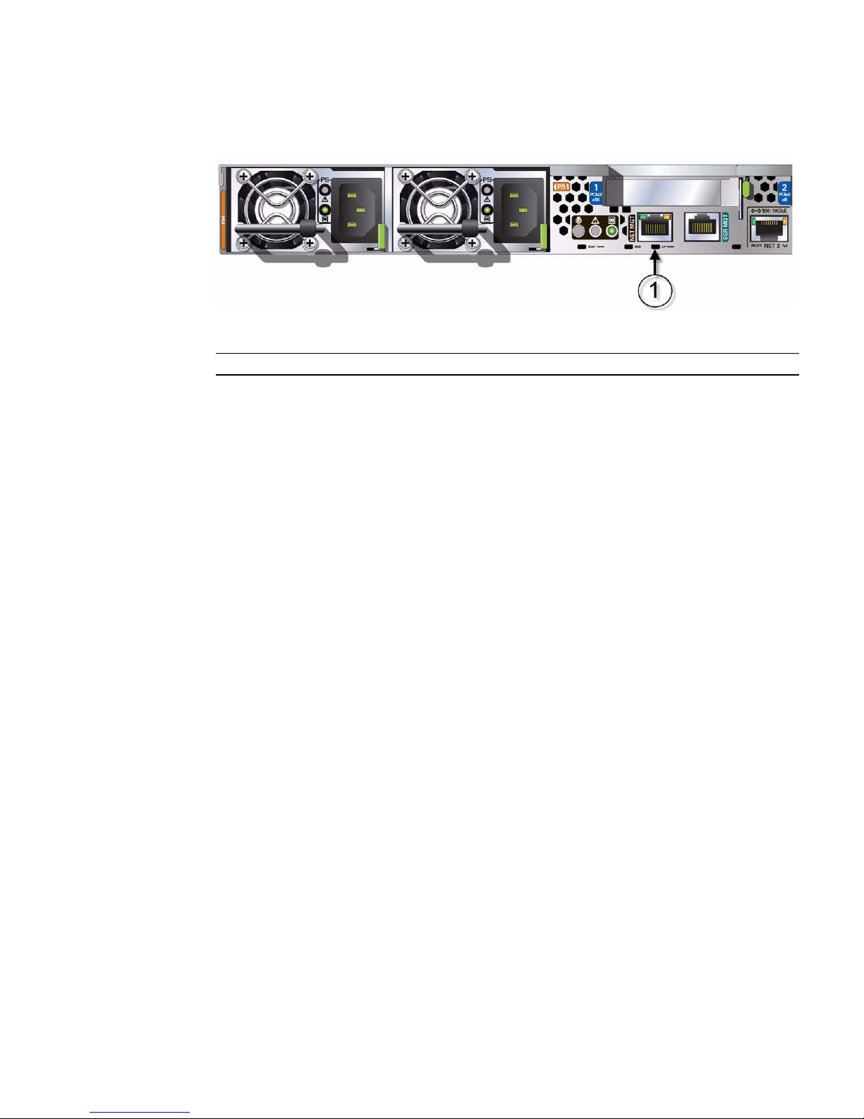
FIGURE: SP Reset Pinhole Button Location
Figure Legend
1 SP Reset pinhole button
The SP reboots. You must log in again to continue working in Oracle ILOM.
▼ Recover Root Account Password
If necessary, system administrators can recover the preconfigured Oracle ILOM local
root account or the password for the local root account by using the preconfigured
Oracle ILOM default password.
To recover the root account password you need a local serial management port (SER
MGT) connection to Oracle ILOM. In addition, if the Physical Presence State is
enabled (the default) in Oracle ILOM, you must prove that you are physically present
at the server.
To recover the root account password, perform these steps:
1. Establish a local serial management connection to Oracle ILOM and log in to
Oracle ILOM using the default user account.
For example: SUNSP-000000000 login: default
Press and release the physical presence button
Press return when this is completed...
2. Prove physical presence at the server.
To prove physical presence at the server, press the Locator button on the front of
the server.
For the exact location of the Locator button, see FIGURE: Front Panel With Four
3.5-inch Drives Configuration on page 8 or FIGURE: Front Panel With Eight
2.5-inch Drives Configuration on page 10.
Connecting to Oracle ILOM 81
Page 94

3. Return to your serial console and press Enter.
You will be prompted for a password.
4. Type the password for the default user account: defaultpassword.
5. Reset the account password or re-create the root account.
For more information, refer to the section on "Configuring Local User Accounts" in
the Oracle Integrated Lights Out Manager (ILOM) 3.1 Configuration and Maintenance
Guide at http://www.oracle.com/pls/topic/lookup?ctx=ilom31.
82 Sun Server X3-2 Installation Guide • April 2014
Page 95

Setting Up Software and Firmware
Using Oracle System Assistant
Oracle System Assistant is the preferred application for setting up your system
software and firmware. Oracle System Assistant is an embedded, task-based server
provisioning tool that enables you to perform initial server setup and maintenance
for some Oracle x86 servers.
Using Oracle System Assistant, you can install a supported Linux, Oracle VM, or
Windows operating system, update your server to the latest software release, and
configure server hardware.
This section describes how to set up the software and firmware for the server using
Oracle System Assistant. It includes information about the following tasks.
Description Links
Set up software and firmware Using Oracle
System Assistant.
Set up an operating system and drivers
using Oracle System Assistant.
“Set Up Software and Firmware” on page 84
“Setting Up an Operating System and
Drivers” on page 86
Related Information
■ “Installation Procedure Overview” on page 2
■ “Attaching Data Cables and Power Cords to the Server” on page 60
■ Sun Server X3-2 Administration Guide, “Setting Up the Server Using Oracle System
Assistant” on page 35
83
Page 96
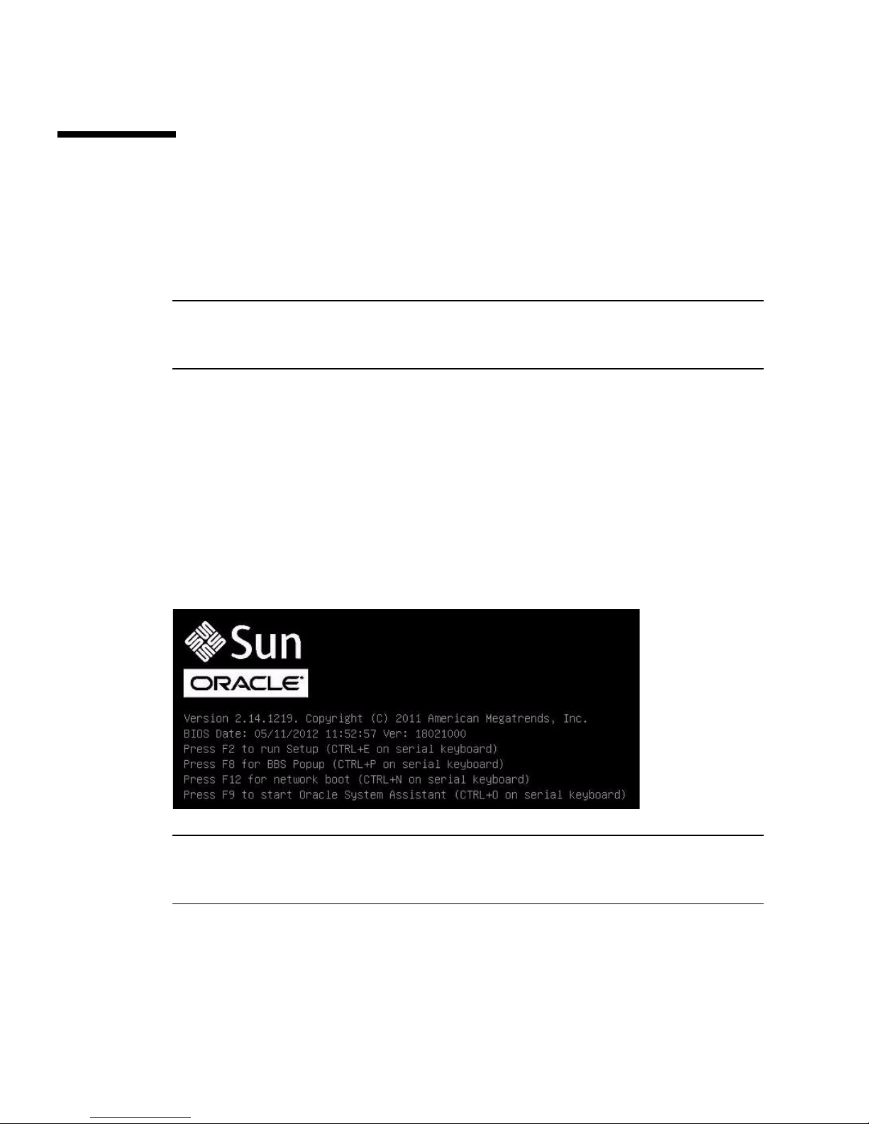
▼ Set Up Software and Firmware
1. Connect the data cables and power cords to the server.
Follow the cabling instructions in “Attaching Data Cables and Power Cords to the
Server” on page 60.
Note – You can also access Oracle System Assistant using the Remote Console
feature of Oracle ILOM. See “Connecting to Oracle ILOM” on page 63 for
information about connecting to Oracle ILOM and using the Remote Console feature.
2. Ensure that the server is in standby power mode.
When the server is in standby power mode, the Power/OK LED on the front panel
blinks slowly.
3. Press the Power button on the front panel of the server to power on the server to
full power.
The server boots, and power-on self-test (POST) and boot messages appear on the
monitor.
Stay with the server. You need to interrupt the boot process.
The BIOS screen appears.
Note – The next events occur very quickly; therefore, focused attention is needed for
the following steps. Watch carefully for these messages as they appear on the screen
for a brief time.
4. Watch for the prompt to press the F9 key, and when it appears, press F9.
The Oracle System Assistant application is started, and the System Overview
screen appears.
84 Sun Server X3-2 Installation Guide • April 2014
Page 97
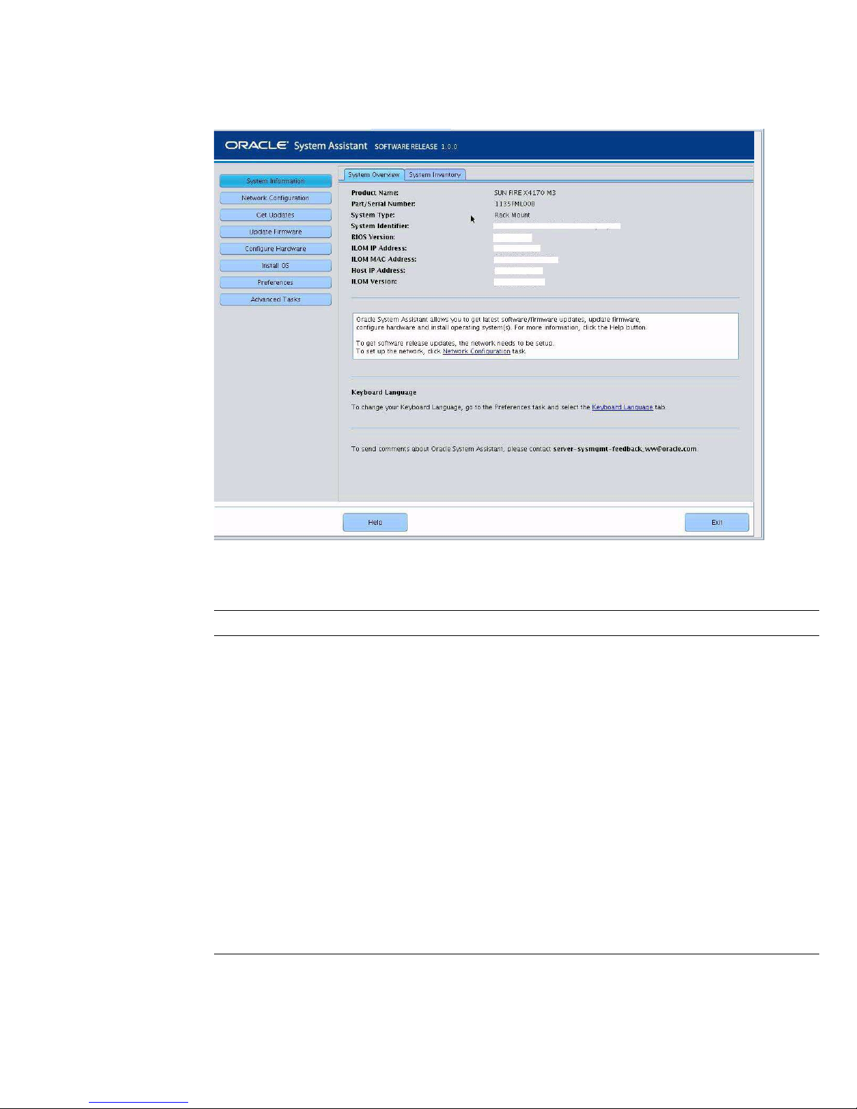
5. Use Oracle System Assistant to perform the tasks listed in the following table.
Task Oracle System Assistant Screen
1 Review system information and
System Information
inventory.
2 Set up a network connection. Network Configuration
3 Update to the latest software release
Get Updates
and product documentation.
4 Update Oracle ILOM, BIOS, disk
Update Firmware
expander, or HBA firmware, if
needed.
5 Configure Oracle ILOM. Configure Hardware > Service Processor
Configuration
6 Configure RAID. Configure Hardware > RAID Configuration
7 Install a Linux, Oracle VM, or
Windows operating system or drivers.
Install OS
For more information see “Setting Up an Operating
System and Drivers” on page 86 or the installation
guide for the OS you plan to install.
Setting Up Software and Firmware Using Oracle System Assistant 85
Page 98

Setting Up an Operating System and
Drivers
You can configure a preinstalled operating system (OS), or install a supported OS for
your server. The following table describes how to access information about installing
or configuring an OS.
Which OS do you
What do you
want to do?
want to configure
or install? Use this tool or documentation
Configure a
preinstalled
OS
Install an OS Linux OS,
Preinstalled
Oracle Solaris
OS
Preinstalled
Oracle Linux
Preinstalled
Oracle VM
Oracle VM, or
Windows OS
Oracle Solaris
OS or VMware
ESXi
“Configuring the Preinstalled Oracle Solaris 11 Operating
System” on page 129
“Configuring the Preinstalled Oracle Linux 6.x Operating
System” on page 137
“Configuring the Preinstalled Oracle VM 3.x Software” on
page 143
Oracle System Assistant or the installation guide for the OS
• Sun Server X3-2 Installation Guide for Linux Operating
Systems, “Installing the Linux Operating System” on
page 23
• Sun Server X3-2 Installation Guide for Oracle VM,
“Installing Oracle VM” on page 19
• Sun Server X3-2 Installation Guide for Windows Operating
Systems, “Installing Windows Server Operating System”
on page 23
Installation guide for the OS
• Sun Server X3-2 Installation Guide for Oracle Solaris
Operating System, “Installing the Oracle Solaris Operating
System” on page 19
• Sun Server X3-2 Installation Guide for VMware ESXi,
“Install VMware ESXi Using Local or Remote Media” on
page 21
86 Sun Server X3-2 Installation Guide • April 2014
Page 99

What do you
want to do?
Which OS do you
want to configure
or install? Use this tool or documentation
Install OS
drivers
Any supportedOSOracle System Assistant or the installation guide for the OS
• Sun Server X3-2 Installation Guide for Linux Operating
Systems, “Installing the Linux Operating System” on
page 23
• Sun Server X3-2 Installation Guide for Oracle VM,
“Installing Oracle VM” on page 19
• Sun Server X3-2 Installation Guide for Windows Operating
Systems, “Installing Windows Server Operating System”
on page 23
• Sun Server X3-2 Installation Guide for Oracle Solaris
Operating System, “Installing the Oracle Solaris Operating
System” on page 19
• Sun Server X3-2 Installation Guide for VMware ESXi,
“Install VMware ESXi Using Local or Remote Media” on
page 21
Related Information
■ “Set Up Software and Firmware” on page 84
■ “Configuring the Preinstalled Oracle Solaris 11 Operating System” on page 129
■ “Configuring the Preinstalled Oracle Linux 6.x Operating System” on page 137
■ “Configuring the Preinstalled Oracle VM 3.x Software” on page 143
Setting Up Software and Firmware Using Oracle System Assistant 87
Page 100

88 Sun Server X3-2 Installation Guide • April 2014
 Loading...