

Page 1

Sun Server X2-4
(formerly Sun Fire X4470 M2)
Service Manual
Part No.: E20784-06
April 2013
Page 2

Copyright ©2011, 2012, 2013 , Oracle and/or its affiliates. Allrights reserved.
This softwareand related documentationare provided under a license agreement containingrestrictions onuse anddisclosure and are protected by
intellectual propertylaws. Exceptas expressly permittedin yourlicense agreement or allowed by law, you may not use, copy,reproduce, translate,
broadcast, modify, license,transmit, distribute,exhibit, perform,publish, ordisplay anypart, inany form,or byany means.Reverse engineering,
disassembly, or decompilation of this software, unlessrequired by law for interoperability, is prohibited.
The informationcontained hereinis subjectto changewithout noticeand isnot warrantedto beerror-free.If youfind anyerrors, please report them to us
in writing.
If thisis softwareor related software documentation that is delivered tothe U.S.Government oranyone licensingit onbehalf ofthe U.S.Government, the
following noticeis applicable:
U.S. GOVERNMENTEND USERS.Oracle programs,including anyoperating system,integrated software, anyprograms installed on the hardware,
and/or documentation,delivered toU.S. Governmentend usersare "commercial computer software" pursuantto theapplicable FederalAcquisition
Regulation andagency-specific supplementalregulations. Assuch, use,duplication, disclosure, modification,and adaptationof theprograms, including
any operatingsystem, integratedsoftware, anyprograms installed on the hardware,and/or documentation,shall besubject tolicense termsand license
restrictions applicableto theprograms. No other rights are granted to the U.S. Government.
This software orhardware is developed for generaluse ina varietyof information management applications. It is not developed orintended foruse in any
inherently dangerous applications,including applicationsthat maycreate a risk of personal injury.If youuse thissoftware or hardwarein dangerous
applications, thenyou shallbe responsibleto takeall appropriate fail-safe,backup, redundancy, and other measures to ensure itssafe use.Oracle
Corporation andits affiliatesdisclaim anyliability forany damagescaused byuse ofthis software orhardware in dangerousapplications.
Oracle andJava areregistered trademarks of Oracle and/or its affiliates.Other namesmay betrademarks oftheir respective owners.
Intel andIntel Xeonare trademarksor registered trademarks of Intel Corporation. All SPARC trademarks areused underlicense andare trademarks or
registered trademarks of SPARCInternational, Inc. AMD, Opteron, theAMD logo,and theAMD Opteron logo are trademarksor registered trademarksof
Advanced MicroDevices. UNIXis aregistered trademark of The Open Group.
This software or hardware and documentation may provide access to or information on content, products, and services from third parties. Oracle
Corporation and its affiliates are not responsible for and expressly disclaim all warranties of any kind with respect to third-party content, products, and
services. Oracle Corporation and its affiliates will not be responsible for any loss, costs, or damages incurred due to your access to or use of third-party
content, products, or services.
Copyright ©2011, 2012, 2013, Oracle et/ou ses affiliés.Tous droits réservés.
Ce logicielet ladocumentation quil’accompagne sontprotégés parles loissur lapropriété intellectuelle. Ils sont concédés sous licence et soumis à des
restrictions d’utilisationet dedivulgation. Saufdisposition devotre contrat de licence ou de la loi, vous ne pouvez pas copier, reproduire, traduire,
diffuser, modifier, breveter, transmettre, distribuer, exposer,exécuter, publierou afficherle logiciel,même partiellement,sous quelqueforme etpar
quelque procédéque cesoit. Parailleurs, ilest interdit deprocéder à toute ingénierie inverse du logiciel, de le désassembler ou de le décompiler, excepté à
des finsd’interopérabilité avecdes logicielstiers outel queprescrit par la loi.
Les informationsfournies dansce documentsont susceptiblesde modificationsans préavis.Par ailleurs,Oracle Corporationne garantitpas qu’elles
soient exemptesd’erreurs etvous invite,le caséchéant, àlui enfaire part par écrit.
Si celogiciel, oula documentationqui l’accompagne,est concédésous licenceau Gouvernementdes Etats-Unis,ou àtoute entitéqui délivrela licencede
ce logicielou l’utilisepour lecompte duGouvernement desEtats-Unis, lanotice suivantes’applique :
U.S. GOVERNMENTEND USERS.Oracle programs,including anyoperating system,integrated software, anyprograms installed on the hardware,
and/or documentation,delivered toU.S. Governmentend usersare "commercial computer software" pursuantto theapplicable FederalAcquisition
Regulation andagency-specific supplementalregulations. Assuch, use,duplication, disclosure, modification,and adaptationof theprograms, including
any operatingsystem, integratedsoftware, anyprograms installed on the hardware,and/or documentation,shall besubject tolicense termsand license
restrictions applicableto theprograms. No other rights are granted to the U.S. Government.
Ce logicielou matériela étédéveloppé pourun usagegénéral dansle cadred’applications degestion desinformations. Celogiciel oumatériel n’estpas
conçu nin’est destinéà êtreutilisé dansdes applicationsà risque,notamment dansdes applicationspouvant causerdes dommagescorporels. Si vous
utilisez celogiciel oumatériel dansle cadred’applications dangereuses, ilest devotre responsabilité de prendre toutesles mesures desecours, de
sauvegarde, deredondance et autres mesures nécessaires àson utilisation dans desconditions optimalesde sécurité.Oracle Corporationet sesaffiliés
déclinent touteresponsabilité quantaux dommagescausés parl’utilisation dece logicielou matérielpour cetype d’applications.
Oracle etJava sontdes marquesdéposées d’OracleCorporation et/oude sesaffiliés.Tout autre nommentionné peutcorrespondre à des marques
appartenant àd’autres propriétaires qu’Oracle.
Intel etIntel Xeonsont desmarques oudes marques déposéesd’Intel Corporation.Toutes lesmarques SPARC sont utilisées sous licence et sont des
marques oudes marques déposéesde SPARC International, Inc. AMD, Opteron, le logo AMD et le logo AMD Opteron sontdes marques ou des marques
déposées d’AdvancedMicro Devices.UNIX estune marque déposéed’The OpenGroup.
Ce logicielou matérielet ladocumentation quil’accompagne peuventfournir desinformations oudes liensdonnant accèsà descontenus, desproduits et
des servicesémanant detiers. OracleCorporation etses affiliésdéclinent touteresponsabilité ou garantie expresse quant aux contenus, produits ou
services émanantde tiers.En aucuncas, OracleCorporation etses affiliésne sauraientêtre tenus pour responsables des pertes subies, des coûts
occasionnés oudes dommagescausés parl’accès àdes contenus,produits ouservices tiers,ou àleur utilisation.
Please
Recycle
Page 3

Contents
Using This Documentation xi
1. Sun Server X2-4 Service Manual Overview 1–1
1.1 System Overview 1–1
1.1.1 Intel Xeon E7 Platform 1–1
1.1.2 Block Diagrams 1–2
1.1.3 Processors (CPUs) 1–3
1.1.4 Memory 1–4
1.1.5 Cooling 1–5
1.1.6 Input/Output (I/O) 1–6
1.1.7 Summary of Supported Components and Capabilities 1–7
1.2 Server Front Panel Features 1–9
1.3 Server Back Panel Features 1–10
1.4 Performing Service Related Tasks 1–11
2. Preparing to Service the Sun Server X2-4 2–1
2.1 Location of Replaceable Components 2–1
2.2 Tools and Equipment Needed 2–3
2.3 Performing Electrostatic Discharge and Static Prevention Measures 2–3
2.3.1 Using an Antistatic Wrist Strap 2–3
iii
Page 4

2.3.2 Using an Antistatic Mat 2–4
2.4 Positioning the Server for Maintenance 2–4
▼ Extend the Server to the Maintenance Position 2–4
2.5 Releasing the Cable Management Arm 2–5
▼ Release the CMA 2–5
2.6 Powering Off the Server 2–6
▼ Power Off the Server Using the Service Processor Command-Line
Interface 2–7
2.7 Removing the Server Top Cover 2–8
▼ Remove the Server Top Cover 2–8
2.8 Removing or Installing Filler Panels 2–9
2.9 Attaching Devices to the Server 2–10
2.9.1 Connector Locations 2–10
2.9.2 Cabling the Server 2–11
▼ Cable the Server 2–11
3. Servicing CRU Components That Do Not Require Server Power Off 3–1
3.1 Servicing Disk Drives (CRU) 3–1
3.1.1 Disk Drive Status LED Reference 3–1
3.1.2 Removing and Installing Disk Drives and Disk Drive Filler Panels
3–2
▼ Remove a Disk Drive Filler Panel 3–2
▼ Remove a Disk Drive 3–3
▼ Install a Disk Drive 3–4
▼ Install a Disk Drive Filler Panel 3–5
3.2 Servicing Fan Modules (CRU) 3–5
3.2.1 About Server Fans 3–6
3.2.2 Fan Module LED Reference 3–6
3.2.3 Detecting Fan Module Failure 3–7
3.2.4 Removing and Installing Fan Modules 3–7
iv Sun Server X2-4 Service Manual • April 2013
Page 5

▼ Remove a Fan Module 3–8
▼ Install a Fan Module 3–9
3.3 Servicing Power Supplies (CRU) 3–11
3.3.1 Power Supply LED Reference 3–11
3.3.2 Detecting a Power Supply Failure 3–12
3.3.3 Removing and Installing Power Supplies 3–12
▼ Remove a Power Supply 3–13
▼ Install a Power Supply 3–14
4. Servicing CRU Components That Require Server Power Off 4–1
4.1 Servicing Memory Risers and DIMMs (CRU) 4–1
4.1.1 CPUs, Memory Risers, and DIMMs Physical Layout 4–2
4.1.2 Memory Riser Population Rules 4–3
4.1.3 Memory Riser DIMM Population Rules 4–4
4.1.4 Memory Performance Guidelines 4–5
4.1.4.1 Recommended Memory Placement 4–6
4.1.5 DIMM Fault Isolation 4–7
4.1.6 Supported DIMMs 4–7
4.1.7 Unsupported DIMMs 4–7
4.1.8 Removing and Installing Memory Risers, DIMMs, and Filler
Panels 4–8
▼ Remove a Memory Riser Filler Panel 4–8
▼ Remove a DIMM Filler Panel 4–8
▼ Remove a Memory Riser and DIMM 4–9
▼ Install Memory Risers and DIMMs 4–13
▼ Install a Memory Riser Filler Panel 4–16
▼ Install a DIMM Filler Panel 4–16
4.2 Servicing PCIe Cards (CRU) 4–17
4.2.1 PCIe Card Configuration Rules 4–17
Contents v
Page 6

4.2.2 PCIe Cards With Bootable Devices 4–18
4.2.3 Avoiding PCI Resource Exhaustion Errors 4–18
4.2.4 Removing and Installing PCIe Cards and PCIe Card Filler Panels
4–19
▼ Remove a PCIe Card Filler Panel 4–19
▼ Remove a PCIe Card 4–20
▼ Install a PCIe Card 4–22
▼ Install a PCIe Card Filler Panel 4–23
4.3 Servicing the DVD Drive and DVD Driver Filler Panel (CRU) 4–24
▼ Remove the DVD Drive or DVD Drive Filler Panel 4–24
▼ Install the DVD Drive or DVD Drive Filler Panel 4–25
4.4 Servicing the System Lithium Battery (CRU) 4–27
▼ Remove the System Battery 4–27
▼ Install the System Battery 4–28
5. Servicing FRU Components 5–1
5.1 Servicing the CPU and Heatsink (FRU) 5–1
5.1.1 CPU Placement 5–2
5.1.2 Removing and Installing a Heatsink Filler Panel, CPU Cover Plate,
Heatsink, and CPU 5–2
▼ Remove a Heatsink Filler Panel and CPU Cover Plate 5–2
▼ Remove a Heatsink and CPU 5–3
▼ Install a Heatsink and CPU 5–5
▼ Install a Heatsink Filler Panel 5–8
5.2 Servicing the Fan Board (FRU) 5–8
▼ Remove the Fan Board 5–8
▼ Install the Fan Board 5–10
5.3 Servicing the Power Supply Backplane (FRU) 5–12
▼ Remove the Power Supply Backplane 5–12
▼ Install the Power Supply Backplane 5–14
vi Sun Server X2-4 Service Manual • April 2013
Page 7

5.4 Servicing the Disk Drive Backplane (FRU) 5–15
▼ Remove the Disk Drive Backplane 5–16
▼ Install the Disk Drive Backplane 5–17
5.5 Servicing the Motherboard (FRU) 5–19
▼ Remove the Motherboard 5–19
▼ Install the Motherboard 5–20
6. Returning the Server to Operation 6–1
6.1 Replacing the Server Top Cover 6–1
▼ Replace the Server Top Cover 6–1
6.2 Returning the Server to the Normal Rack Position 6–2
▼ Return the Server to the Normal Rack Position 6–2
6.3 Powering On the Server 6–3
▼ Power On the Server 6–3
7. Servicing the Server at Boot Time 7–1
7.1 Powering On the Server 7–1
7.2 About the BIOS 7–2
7.3 Default BIOS Power-On Self-Test (POST) Events 7–2
7.4 BIOS POST F1 and F2 Errors 7–4
7.5 How BIOS POST Memory Testing Works 7–7
7.6 Ethernet Port Device and Driver Naming 7–8
7.6.1 Ethernet Port Booting Priority 7–9
7.7 BIOS Setup Utility Menus 7–9
7.8 Performing Common BIOS Procedures 7–11
▼ Access the BIOS Setup Utility 7–12
▼ Reset the BIOS Password 7–13
▼ Configure Support for TPM 7–15
▼ Configure SP LAN Settings 7–18
Contents vii
Page 8

▼ Configure Option ROM Settings 7–21
7.8.1 Configuring Serial Port Sharing 7–22
▼ Assign Serial Port Output Using the CLI 7–23
▼ Assign Serial Port Output Using the Web Interface 7–23
7.9 BIOS and SP Updates 7–24
7.10 BIOS Configuration Tool 7–24
8. Troubleshooting the Server and ILOM Defaults 8–1
8.1 Troubleshooting the Server 8–1
8.2 Diagnostic Tools 8–2
8.2.1 Diagnostic Tool Documentation 8–3
8.3 Using the Preboot Menu Utility 8–4
8.3.1 Accessing the Preboot Menu 8–5
8.3.1.1 Prerequisites for Accessing the Preboot Menu 8–5
▼ Access the Preboot Menu 8–6
▼ Edit Preboot Menu for Remote Serial Access 8–7
8.3.1.2 Edit Mode Settings in Preboot Menu 8–9
8.3.2 Restoring Oracle ILOM to Default Settings 8–9
▼ Reset Oracle ILOM Configuration Using the Preboot Menu 8–
10
8.3.3 Restoring Oracle ILOM Access to the Serial Console 8–10
▼ Restore Access to the Serial Console Using the Preboot Menu
8–10
8.3.4 Restoring the SP Firmware Image 8–11
8.3.4.1 Prerequisites for Restoring SP Firmware Using the
Preboot Menu 8–12
▼ Restore the SP Firmware Image Using the Preboot Menu 8–12
8.3.5 Preboot Menu Command Summary 8–13
8.4 Contacting Support 8–15
8.5 Locating the Chassis Serial Number 8–16
viii Sun Server X2-4 Service Manual • April 2013
Page 9

A. Server Specifications A–1
A.1 Physical Specifications A–1
A.2 Electrical Specifications A–1
A.3 Environmental Requirements A–2
B. BIOS Setup Utility Menus B–1
B.1 BIOS Main Menu Selections B–2
B.2 BIOS Advanced Menu Selections B–3
B.3 BIOS PCIPnP Menu Selections B–12
B.4 BIOS Boot Menu Selections B–14
B.5 BIOS Security Menu Selections B–16
B.6 BIOS IO/MMIO Menu Selections B–17
B.7 BIOS Chipset Menu Selections B–19
B.8 BIOS Exit Menu Selections B–21
C. Connector Pinouts C–1
C.1 USB Connectors C–1
C.2 Serial Connector C–2
C.3 Gigabit-Ethernet Connectors C–2
C.4 Network Management Port Connector C–3
C.5 Video Connectors C–4
C.6 Serial Attached SCSI (SAS) Connector C–4
D. Getting Server Firmware and Software D–1
D.1 Firmware and Software Updates D–1
D.2 Firmware and Software Access Options D–2
D.3 Available Software Release Packages D–2
D.4 Accessing Firmware and Software D–3
▼ Download Firmware and Software Using My Oracle Support D–3
D.4.1 Requesting Physical Media D–4
Contents ix
Page 10

D.4.2 Gathering Information for the Physical Media Request D–5
▼ Request Physical Media (Online) D–5
▼ Request Physical Media (By Phone) D–6
D.5 Installing Updates D–7
D.5.1 Installing Firmware D–7
D.5.2 Installing Hardware Drivers and OS Tools D–8
Index Index–1
x Sun Server X2-4 Service Manual • April 2013
Page 11

Using This Documentation
This service manual explains how to replace parts in Oracle’s Sun Server X2-4 and
how to use and maintain the system.
Note – The Sun Server X2-4 was formerly named the Sun Fire X4470 M2 server. This
former name might still appear in the software. The new product name does not
indicate any change in system features or functionality.
This document is intended for system administrators, network administrators, and
service technicians who have an understanding of server systems.
Note – This service manual describes how to replace both customer-replaceable
units (CRUs) and field-replaceable units (FRUs). FRUs should only be serviced by
authorized service providers.
■ “Before You Read This Document” on page xi
■ “Getting the Latest Software and Firmware” on page xii
■ “Related Documentation” on page xii
■ “Support and Accessibility” on page xiii
Before You Read This Document
It is important that you review the safety guidelines in the Sun Server X2-4 Safety and
Compliance Guide and in the Important Safety Information for Sun Hardware Systems.
xi
Page 12

Getting the Latest Software and
Firmware
Firmware, drivers, and other hardware-related software for each Oracle x86 server,
server module (blade), and blade chassis are updated periodically.
For information and download instructions, see Appendix D.
Related Documentation
Documentation Link
All Oracle documentation http://www.oracle.com/documentation
Sun Server X2-4 http://www.oracle.com/pls/topic/lookup?ctx=
SunServerX2-4
Oracle Integrated Lights
Out Manager (ILOM) 3.0
Oracle Integrated Lights
Out Manager (ILOM) 3.1
(for Sun Server X2-4
Software Release 1.3 and
above)
Oracle Hardware
Installation Assistant
http://www.oracle.com/pls/topic/lookup?ctx=
ilom30
http://www.oracle.com/pls/topic/lookup?ctx=
ilom31
http://www.oracle.com/pls/topic/lookup?ctx=
hia
xii Sun Server X2-4 Service Manual • April 2013
Page 13

Support and Accessibility
Description Links
Access electronic support
through My Oracle Support
Learn about Oracle’s
commitment to accessibility
http://support.oracle.com
For hearing impaired:
http://www.oracle.com/accessibility/support.
html
http://www.oracle.com/us/corporate/accessibi
lity/index.html
Using This Documentation xiii
Page 14

xiv Sun Server X2-4 Service Manual • April 2013
Page 15

CHAPTER
1
Sun Server X2-4 Service Manual
Overview
This chapter provides an overview of the Sun Server X2-4.
It contains the following topics:
■ Section 1.1 “System Overview” on page 1-1
■ Section 1.2 “Server Front Panel Features” on page 1-9
■ Section 1.3 “Server Back Panel Features” on page 1-10
■ Section 1.4 “Performing Service Related Tasks” on page 1-11
1.1 System Overview
Oracle’s Sun Server X2-4 is a 3 rack unit (RU) rackmount server that uses the Intel
Xeon E7 platform. This section describes the major features, components, and
capabilities of the server.
1.1.1 Intel Xeon E7 Platform
The Intel Xeon E7 platform is based on the Intel Xeon Processor E7-4800 Series and
uses the Intel 7500 Chipset I/O hub (IOH) as its primary chipset. The platform uses
the Intel QuickPath Interface (QPI), a high-speed, differentially signaled,
point-to-point interface that forms a communication fabric among the processors
(CPUs) and IOHs in the system.
The Sun Server X2-4 uses two Intel 7500 Chipset I/O hubs, each connected to two of
the four CPUs. One of these I/O hubs is designated the legacy I/O hub and has a
connection to the Intel I/O Controller Hub 10 (ICH10) southbridge component.
1-1
Page 16

1.1.2 Block Diagrams
FIGURE 1-1 shows a block diagram for a Sun Server X2-4 with four CPUs.
FIGURE 1-2 shows a block diagram for a Sun Server X2-4 with two CPUs.
Note – In the diagrams, the PCIe SAS/RAID Controller is shown as installed in Slot
2. If a particular SAS/RAID Controller has specific cooling requirements, it might
have to be installed in Slot 4. For information about cooling requirements, refer to the
Sun Server X2-4 Product Notes.
FIGURE 1-1 Four CPU Block Diagram
1-2 Sun Server X2-4 Service Manual • April 2013
Page 17

FIGURE 1-2 Two CPU Block Diagram
1.1.3 Processors (CPUs)
The Sun Server X2-4 supports two or four processors (CPUs), as shown in FIGURE 1-1
and FIGURE 1-2. The two-CPU configuration must have CPUs (with heatsinks) in
sockets 0 and 2 and heatsink filler panels installed in sockets 1 and 3.
In a two-CPU configuration, all three QPI interconnects and both CPUs must be
operational. The four-CPU configuration offers a greater level of resiliency with
redundant QPI interconnects that allow working CPUs to route around a disabled
CPU as the system starts.
Chapter 1 Sun Server X2-4 Service Manual Overview 1-3
Page 18

Features of each Intel Xeon Processor E7-4800 Series include:
■ Up to ten cores with Hyper-Threading (two threads/core)
■ Up to 30MB shared last level cache
■ 32nm process technology
■ Two integrated memory controllers with four Intel Scalable Memory Interconnects
(SMI channels)
■ Supports speeds of DDR3-1067 MT/s via an Intel 7510 Scalable Memory Buffer
■ Four full-width, bidirectional Intel QuickPath interconnects (QPI links)
■ 6.4 GT/s (12.8 GB/s per direction)
■ Automatic self-healing by degrading to half-width or quarter-width link
operation
■ CPU Thermal Design Power (TDP) of 105W or 130W
Note – For more information about Intel QuickPath Interconnects, refer to Weaving
High Performance Multiprocessor Fabric from Intel Press at
http://www.intel.com/intelpress/sum_qpi.htm.
1.1.4 Memory
Each CPU in the Sun Server X2-4 has four SMI channels leading to Intel 7510 Scalable
Memory Buffers (located on two memory risers). Each memory buffer has an SMI
link to the CPU and two DDR3 interfaces. Each SMI interface can operate at speeds
of 6.4 GT/s, which correspond to DDR3 operation at 1067 MT/s. From the CPU to
the Intel 7510 Scalable Memory Buffer, the SMI interface supports 11 lanes (9 data + 1
CRC + 1 spare). From the Intel 7510 Scalable Memory Buffer to the CPU, the SMI
interface supports 14 lanes (12 data + 1 CRC + 1 spare). The CPU retries memory
transactions that incur a CRC error. For persistent errors, the SMI link has spare lanes
for automatic self-healing.
The system supports a maximum of eight memory risers (4 CPU configuration) or
four memory risers (2 CPU configuration). Each riser houses 8 DIMM slots for the
four DDR3 channels. The system can operate with 0, 2, 4, 6 or 8 DIMMs on a given
riser. For maximum performance, install at least two ranks of DIMMs on every
available DDR3 channel (for example, 4 DIMMs per riser with two risers per CPU).
Each of two memory controllers in a CPU operates its two SMI channels as a
lock-step pair. The memory controller treats each pair of DDR3 channels behind the
two memory buffers as a 144-bit-wide DRAM interface. As a result, the DIMMs must
be installed in pairs, with identical DIMMs in each pair.
The DDR3 interfaces include the following features:
1-4 Sun Server X2-4 Service Manual • April 2013
Page 19

■ Accommodates x4 and x8 Single-Rank, Dual-Rank, Quad-Rank RDIMMs
■ Supports up to 2 RDIMMs per DDR3 channel (8 DIMM slots per memory riser)
■ DDR3 speed: 1067 MT/s or 978 MT/s (dictated by SMI speeds of CPUs)
■ DRAM Technology: 2 or 4 Gb die, 1.35-volt or 1.5-volt operation
■ DIMM Capacity: 4, 8, 16 GB (16 GB with Quad-Rank DIMMs only)
■ Currently supported DIMMs are PC3L RDIMMs, dual-rank in 4-, 8-, and
quad-rank 16-GB sizes
For more information about CPUs, memory risers, and memory layout, including
guidelines for populating memory risers and DIMMs, see Section 4.1 “Servicing
Memory Risers and DIMMs (CRU)” on page 4-1.
FIGURE 1-3 shows the architecture of the server memory.
FIGURE 1-3 Memory Architecture
1.1.5 Cooling
The Sun Server X2-4 is cooled from front to back. Cooling occurs in two areas of the
chassis, separated by a plastic dividing wall. In the power supply cooling zone, fans
at the back of the power supplies cool the drive bays as well as the power supplies,
Chapter 1 Sun Server X2-4 Service Manual Overview 1-5
Page 20

by drawing air into the depressurized zone at the right of the chassis. In the main
cooling zones, six 92-mm high-performance fans, arranged in two rows for
redundancy, cool the motherboard, memory risers, and I/O cards. The motherboard
is divided into three zones and each pair of fans is separately regulated to cool that
zone. Since the main cooling zones are pressurized, it is important to maintain the
seal of the dividing wall so that the power supply units can draw air through the
drive bay.
The unrestricted airflow over the motherboard minimizes system noise. Dividing the
cooling into zones allows for greater use of system resources, since each zone can
operate independently at its highest efficiency.
FIGURE 1-4 shows the cooling zones.
FIGURE 1-4 Server Cooling Zones
Figure Legend
1 Power supply cooling zone
2 Chassis cooling zone 2
3 Chassis cooling zone 1
4 Chassis cooling zone 0
1.1.6 Input/Output (I/O)
For internal storage, the server chassis provides:
1-6 Sun Server X2-4 Service Manual • April 2013
Page 21

■ Six 2.5-inch drive bays, accessible through the front panel. The supported drive
interfaces for each bay depend on the host bus adapter (HBA) chosen.
■ An optional slot-loading DVD+/-RW drive on front of the server, below the drive
bays. This SATA DVD connects to a USB-SATA bridge, so that is appears to the
system software as a USB storage device.
■ One internal high-speed USB port on the motherboard. This port can hold a USB
flash device for system booting.
In addition, the service processor can present virtual USB storage devices to the
system.
The ICH10 southbridge on the motherboard provides six built-in SATA2 (3-Gbit/s)
ports, accessible through two SAS4I connectors (Port 0-3 and Port 4-5). When
configured with any 2.5-inch SAS drives, the system must be equipped with one PCI
Express (PCIe) Gen-2 internal HBA card to support the front 2.5-inch drive bays.
Each offered PCIe Gen-2 HBA has 8 SAS2/SATA2 internal ports accessible through
two SAS4I connectors (Port 0-3 and Port 4-7). Since the drive cage has only six bays,
Port 6-7 of an internal HBA are not used in this system.
With an internal SAS-2 HBA card installed in a PCIe slot, the six bays can handle any
combination of supported SAS and SATA hard disk drives (HDDs) and solid-state
drives (SSDs). If the disk backplane is connected to the built-in ICH10 SATA-2
controller rather than an HBA card, only SATA storage devices will operate. (When a
RAID volume is configured on the HBA card, the drive bays for the RAID members
must hold the same type of storage device.)
1.1.7 Summary of Supported Components and
Capabilities
The following table summarizes the components and capabilities of the Sun Server
X2-4.
Chapter 1 Sun Server X2-4 Service Manual Overview 1-7
Page 22

TABLE 1-1 Sun Server X2-4 Components and Capabilities
Component Sun Server X2-4
Processor (CPU) Supported configurations:
• Two processors installed in socket 0 and socket 2
• Four processors installed in sockets 0 through 3
For the latest information on CPU specifications, go to the Sun x86 Servers web
site and navigate to the Sun Server X2-4 page:
http://www.oracle.com/technetwork/server-storage/sun-x8
6/overview/index.html
Memory Up to eight memory riser modules are supported (two risers per CPU) in the
server chassis. Each riser module supports eight PC3L RDIMMs, allowing up to
sixteen RDIMMs per processor.
• A 2-socket system using four riser modules populated with 16-GB RDIMMs
supports a maximum of 512 GB of system memory.
• A 4-socket system using eight riser modules populated with 16-GB RDIMMs
supports a maximum of 1024 GB of system memory.
Storage devices For internal storage, the server chassis provides:
• Six 2.5-inch drive bays, accessible through the front panel. The supported drive
interfaces for each bay depend on the HBA chosen.
• An optional slot-loading DVD+/-RW drive on front of the server, below the
drive bays. This SATA DVD connects to a USB-SATA bridge, so that is appears
to the system software as a USB storage device.
• One internal high-speed USB port on the motherboard. This port can hold a
USB flash device for system booting.
USB 2.0 ports Two front, two rear, and one internal.
VGA ports One front and one rear high-density DB-15 video ports.
Note - The rear VGA port supports VESA Device Data Channel for monitor
identification.
PCI Express 2.0 I/O slots Ten PCI Express 2.0 slots that accommodate low-profile PCIe cards. All slots
support x8 PCIe connectors. Two slots are also capable of supporting x16 PCIe
connectors.
• Slots 0 and 9: x4 electrical interface
• Slots 1, 2, 4, 6, 7, and 8: x8 electrical interface
• Slots 3 and 5: x8 or x16 electrical interface (x16 connector)
Note - PCI Express slots 3 and 5 will operate as x16 interfaces only when an x16
capable card is installed and the adjacent slot (4 or 6) is unpopulated.
Cluster card slot One specialized slot dedicated for use in storage appliances. The Sun Server X2-4
does not support populating this slot with standard PCIe cards.
1-8 Sun Server X2-4 Service Manual • April 2013
Page 23

TABLE 1-1 Sun Server X2-4 Components and Capabilities (Continued)
Component Sun Server X2-4
PCI Express I/O cards For a list of I/O cards that are customer-orderable options, go to the Sun x86
Servers web site and navigate to the Sun Server X2-4 page:
http://www.oracle.com/technetwork/server-storage/sun-x8
6/overview/index.html
Ethernet ports Four 10/100/1000 RJ-45 GbE ports on rear panel.
Each Network Interface Controller (NIC) supports Intel QuickData Technology,
Intel I/OAT, VMDq, PCI-SIG SR-IOV, IPSec offload, and LinkSec.
Service processor Integrated Baseboard Management Controller (BMC), which supports the
industry-standard IPMI feature set.
Supports remote KVMs, DVD, and floppy over IP (optional license required).
Includes serial port.
Supports Ethernet access to SP through a dedicated 10/100BaseT management
port and optionally through one of the host GbE ports (sideband management).
Power supplies Two hot-swappable power supplies, each with 2000 Watts capacity (from 200 Volts
to 240 Volts), auto-ranging, light load efficiency mode and redundant
over-subscription.
Cooling fans Six hot-swappable, redundant fans at chassis front (top-loading); redundant fans
at each power supply.
Management software Oracle Integrated Lights Out Manager (ILOM)
1.2 Server Front Panel Features
FIGURE 1-5 shows the Sun Server X2-4 front panel and describes its components.
Chapter 1 Sun Server X2-4 Service Manual Overview 1-9
Page 24

FIGURE 1-5 Server Front Panel Features
Figure Legend
1 Locate LED/Locate button: white 10 DB-15 video connector
2 Service Action Required LED: amber 11 SATA DVD drive (optional)
3 Power/OK LED: green 12 Hard disk drive 0 (optional)
4 Power button 13 Hard disk drive 1 (optional)
5 SP OK/Fault LED: green/amber 14 Hard disk drive 2 (optional)
6 Service Action Required LEDs (3) for Fan
Module (FAN), Processor (CPU) and Memory:
amber
7 Power Supply (PS) Fault (Service Action
Required) LED: amber
8 Over Temperature Warning LED: amber 17 Hard disk drive 5 (optional)
9 USB 2.0 connectors (2)
15 Hard disk drive 3 (optional)
16 Hard disk drive 4 (optional)
1.3 Server Back Panel Features
FIGURE 1-6 shows the Sun Server X2-4 back panel and describes its components.
1-10 Sun Server X2-4 Service Manual • April 2013
Page 25

FIGURE 1-6 Server Back Panel Features
Figure Legend
1 Power supply unit 0 status indicator LEDs:
Service action required: amber
DC OK: green
AC OK: green or amber
2 Power supply unit 0 AC inlet 9 USB 2.0 connectors (2)
3 Power supply unit 1 status indicator LEDs:
Service action required: amber
DC OK: green
AC OK: green or amber
4 Power supply unit 1 AC inlet 11 Service processor (SP) network management
5 System status LEDs:
Power/OK: green
Service action required: amber
Locate: white
6 PCIe card slots 0–4 13 DB-15 video connector
7 Cluster card slot
8 Network (NET) 10/100/1000 ports:
NET0–NET3
10 PCIe card slots 5–9
(NET MGT) port
12 Serial management (SER MGT)/RJ-45 serial
port
1.4 Performing Service Related Tasks
This guide contains information and procedures for maintaining and servicing your
server.
TABLE 1-2 identifies the sections in this guide that describe the task you want
to perform.
Chapter 1 Sun Server X2-4 Service Manual Overview 1-11
Page 26

TABLE 1-2 Service Tasks
Service Task See:
Understand server features and processes Section 1.1 “System Overview” on page 1-1
Identify server LEDs and buttons Section 1.2 “Server Front Panel Features” on
page 1-9
Section 1.3 “Server Back Panel Features” on
page 1-10
Prepare to service the server Chapter 2
Replace or upgrade a FRU or CRU Chapter 3
Chapter 4
Chapter 5
Return the server to operation after servicing Chapter 6
Service the server at boot time Chapter 7
Troubleshoot the server Chapter 8
Review server hardware specifications Appendix A
Review BIOS Setup Utility menus Appendix B
Review connector pinouts Appendix C
Download software and firmware for the
server
Appendix D
1-12 Sun Server X2-4 Service Manual • April 2013
Page 27

CHAPTER
2
Preparing to Service the Sun Server
X2-4
This chapter includes the information you might need before servicing the Sun
Server X2-4.
It contains the following topics:
■ Section 2.1 “Location of Replaceable Components” on page 2-1
■ Section 2.2 “Tools and Equipment Needed” on page 2-3
■ Section 2.3 “Performing Electrostatic Discharge and Static Prevention Measures”
on page 2-3
■ Section 2.4 “Positioning the Server for Maintenance” on page 2-4
■ Section 2.5 “Releasing the Cable Management Arm” on page 2-5
■ Section 2.6 “Powering Off the Server” on page 2-6
■ Section 2.7 “Removing the Server Top Cover” on page 2-8
■ Section 2.8 “Removing or Installing Filler Panels” on page 2-9
■ Section 2.9 “Attaching Devices to the Server” on page 2-10
2.1 Location of Replaceable Components
FIGURE 2-1 identifies the replaceable component locations on the Sun Server X2-4,
with the top cover removed.
2-1
Page 28

FIGURE 2-1 Replaceable Component Locations
Figure Legend
1 Motherboard
2 Low-profile PCIe cards
3 Power supplies
4 Power supply backplane
5 Disk backplane
6 System lithium battery
7 CPUs and heatsinks
8 Memory risers
9 Fan board
10 Fan modules
11 DVD dri ve
12 Hard disk drives (HDD)
2-2 Sun Server X2-4 Service Manual • April 2013
Page 29

2.2 Tools and Equipment Needed
To service the system, you need the following tools:
■ No. 2 Phillips screwdriver
■ ESD mat and grounding strap
You might also need a system console device, such as one of the following:
■ PC or workstation with RS-232 serial port
■ ASCII terminal
■ Terminal server
■ Patch panel connected to a terminal server
2.3 Performing Electrostatic Discharge and
Static Prevention Measures
Electrostatic discharge (ESD) sensitive devices, such as the PCIe cards, hard drives,
CPUs, and memory cards, require special handling.
Caution – Circuit boards and hard drives contain electronic components that are
extremely sensitive to static electricity. Ordinary amounts of static electricity from
clothing or the work environment can destroy the components located on these
boards. Do not touch the components along their connector edges.
Caution – You must disconnect AC power cords to both power supplies before
servicing some of the components documented in this guide.
2.3.1 Using an Antistatic Wrist Strap
Wear an antistatic wrist strap when handling components such as disk drive
assemblies, circuit boards, or PCIe cards. When servicing or removing server
components, attach an antistatic strap to your wrist and then to a metal area on the
chassis. Following this practice equalizes the electrical potentials between you and
the server.
Chapter 2 Preparing to Service the Sun Server X2-4 2-3
Page 30

Note – An antistatic wrist strap is not shipped with the servers. However, antistatic
wrist straps are included with customer-replaceable units (CRUs), field-replaceable
units (FRUs), and optional components.
2.3.2 Using an Antistatic Mat
Place ESD-sensitive components such as printed circuit boards on an antistatic mat.
You can use the following items as antistatic mats:
■ Antistatic bag used to wrap a replacement part
■ ESD mat (orderable from Oracle)
■ A disposable ESD mat (shipped with some optional system components)
2.4 Positioning the Server for Maintenance
To remove and replace components in the Sun Server X2-4, you must extend the
server to the maintenance position.
▼ Extend the Server to the Maintenance Position
1. Verify that no cables will be damaged or will interfere when the server is
extended.
Although the cable management arm (CMA) that is supplied with the server is
hinged to accommodate extending the server, you should ensure that all cables
and cords are capable of extending.
2. From the front of the server, release the two slide release latches (
Squeeze the green slide release latches to release the slide rails.
2-4 Sun Server X2-4 Service Manual • April 2013
FIGURE 2-2).
Page 31

FIGURE 2-2 Slide Release Latch
3. While squeezing the slide release latches, slowly pull the server forward until
the slide rails latch.
2.5 Releasing the Cable Management Arm
For some service procedures, if you are using a cable management arm (CMA), you
might have to release the CMA to gain access to the back of the chassis.
▼ Release the CMA
Refer to FIGURE 2-3 for the following procedure.
1. Press and hold the tab [1].
2. Swing the CMA out of the way [2].
When you have finished with the service procedure, swing the CMA closed and
latch it to the left rack rail.
Chapter 2 Preparing to Service the Sun Server X2-4 2-5
Page 32

FIGURE 2-3 Releasing the Cable Management Arm
2.6 Powering Off the Server
Many service procedures require you to remove main power from the server. To
remove main power from the server, use one of the methods described in the
following table.
2-6 Sun Server X2-4 Service Manual • April 2013
Page 33

TABLE 2-1 Shutdown Procedures
Shutdown Method
Graceful shutdown Press and release the Power button on the front panel. Pressing the Power button
causes Advanced Configuration and Power Interface (ACPI)-enabled operating
systems to perform an orderly shutdown of the operating system. Servers not
running ACPI-enabled operating systems will shut down to standby power mode
immediately. When the main power is off, the Power/OK LED on the front panel
flashes slowly, indicating that the server is in standby power mode.
Note - The Power/OK LED might flash several times at 1 Hz to indicate that
power-off is going to occur soon. Main power is still on during this 1-Hz flashing.
Emergency shutdown Press and hold the Power button for at least five seconds until the main power is
off and the server enters standby power mode. When the main power is off, the
Power/OK LED on the front panel flashes slowly, indicating that the server is in
standby power mode.
Caution - All applications and the operating system will be closed abruptly
without saving changes. Data loss or corruption might occur.
Oracle Integrated Lights
Out Manager (ILOM) SP
CLI shutdown
Caution – To completely power off the server, you must disconnect the AC power
cords from the AC inlets on the power supplies on the back panel of the server.
▼ Power Off the Server Using the Service Processor
Command-Line Interface
You can use the Oracle ILOM service processor (SP) to perform a graceful shutdown
of the server and ensure that all of your data is saved and the server is ready for
restart. For additional information, refer to the Oracle Integrated Lights Out Manager
(ILOM) 3.1 Documentation Library at
http://www.oracle.com/pls/topic/lookup?ctx=ilom31.
1. Log in as root. Type:
ssh root@service_processor_ip_address
See “Power Off the Server Using the Service Processor Command-Line Interface”
on page 2-7.
Password: root_password (The default password is changeme.)
The ILOM command-line interface (CLI) prompt appears (->).
Depending on the type of problem, you might want to view server status or log
files, or run diagnostics before you shut down the server.
Chapter 2 Preparing to Service the Sun Server X2-4 2-7
Page 34

2. Power down the server. Type:
-> stop /SYS (for a Graceful shutdown as defined in
-> stop -f /SYS (for an Emergency Shut as defined in
TABLE 2-1)
TABLE 2-1)
2.7 Removing the Server Top Cover
Servicing some components requires you to remove the top cover from the server.
Caution – Removing the top cover without properly powering down the server and
disconnecting the AC power cords from the power supplies will result in a chassis
intrusion switch failure. This failure causes the server to be immediately powered off.
Any changes you make to the memory riser or DIMM configurations will not be
properly reflected in the service processor’s inventory until you replace the top cover.
▼ Remove the Server Top Cover
1. Ensure that the AC power cords are disconnected from the server power
supplies.
2. To unlatch the server top cover, insert your fingers under the two cover latches
and simultaneously lift both latches in an upward motion (
2-8 Sun Server X2-4 Service Manual • April 2013
FIGURE 2-4)[1].
Page 35

FIGURE 2-4 Removing the Server Top Cover
3. Lift the cover slightly and slide it toward the front of the server chassis about
0.5 inch (12 mm).
4. Lift up and remove the top cover [2].
2.8 Removing or Installing Filler Panels
Each server is shipped with module-replacement filler panels for CPUs, disk drives
(HDD or SSD), memory modules (DIMMs), the DVD drive, and the PCIe cards. A
filler panel is an empty metal or plastic enclosure that does not contain any
functioning system hardware or cable connectors.
The filler panels are installed at the factory and must remain in the server until you
replace them with a purchased module to ensure proper airflow through the system.
If you remove a filler panel and continue to operate your system with an empty
Chapter 2 Preparing to Service the Sun Server X2-4 2-9
Page 36

module slot, the server might overheat due to improper airflow. For instructions on
removing or installing a filler panel for a server component, refer to the section in
this guide about servicing that component.
2.9 Attaching Devices to the Server
As part of servicing the Sun Server X2-4, you might have to connect devices to the
server. The following sections describe the locations of connectors on the server and
the order in which you should attach cables and devices to the server.
2.9.1 Connector Locations
FIGURE 2-5 shows and describes the locations of the Sun Server X2-4 back panel
connectors.
FIGURE 2-5 Server Back Panel Connectors
Figure Legend
1 Power supply unit 0 AC inlet 5 Service processor (SP) network management
2 Power supply unit 1 AC inlet 6 Serial management (SER MGT)/RJ-45 serial
3 Gigabit Ethernet ports NET-0, 1, 2, 3 7 DB-15 video connector
4 USB 2.0 ports
2-10 Sun Server X2-4 Service Manual • April 2013
(NET MGT) Ethernet port
port
Page 37

2.9.2 Cabling the Server
When connecting cables to the server, connect them in the order described in the
following procedure.
▼ Cable the Server
Connect external cables to the server in the following order. Refer to FIGURE 2-5 for
the location of connectors on the back of the server.
1. Connect an Ethernet cable to the Gigabit Ethernet (NET) connectors as needed
for OS support.
2. (Optional) If you plan to interact with the system console directly, connect any
additional external devices, such as a mouse and keyboard, to the server’s USB
connectors and/or a monitor to the DB-15 video connector.
3. If you plan to connect to the Oracle ILOM software over the network, connect
an Ethernet cable to the Ethernet port labeled NET MGT.
Note – The service processor (SP) uses the NET MGT (out-of-band) port by default.
You can configure the SP to share one of the sever ’s four 10/100/1000 Ethernet ports
instead. The SP uses only the configured Ethernet port.
4. If you plan to access the Oracle ILOM command-line interface (CLI) using the
management port, connect a serial null modem cable to the RJ-45 serial port
labeled SER MGT.
Chapter 2 Preparing to Service the Sun Server X2-4 2-11
Page 38

2-12 Sun Server X2-4 Service Manual • April 2013
Page 39

CHAPTER
3
Servicing CRU Components That Do
Not Require Server Power Off
This chapter describes how to service customer-replaceable units (CRUs) that do not
require you to power off the server.
It contains the following topics:
■ Section 3.1 “Servicing Disk Drives (CRU)” on page 3-1
■ Section 3.2 “Servicing Fan Modules (CRU)” on page 3-5
■ Section 3.3 “Servicing Power Supplies (CRU)” on page 3-11
Note – Depending on your configuration, in some cases you might have to power off
the server when removing or replacing the disk drive.
3.1 Servicing Disk Drives (CRU)
This section describes how to remove and install disk drives.
Note – The server provides six 2.5-inch drive bays, accessible through the front
panel. The supported drive interfaces for each bay depend on the installed HBA.
3.1.1 Disk Drive Status LED Reference
FIGURE 3-1 shows the disk drive status LEDs. TABLE 3-1 describes the LEDs and their
functions.
3-1
Page 40

FIGURE 3-1 Disk Drive Status LEDs
TABLE 3-1 Disk Drive Status LED Descriptions
Legend LED Symbol Color Lights When...
1 OK to Remove Blue A disk drive can be removed safely
during a hot-plug operation.
2 Service Action Required Amber The system is running and the disk
drive is faulty. The front and rear
panel Service Action Required LEDs
are also lit if the system detects a
disk drive fault.
3 OK/Activity Green Drive is properly inserted into the
system. LED will flash off and on
when the drive is being accessed.
3.1.2 Removing and Installing Disk Drives and Disk
Drive Filler Panels
Use the following procedures to remove and install disk drives and disk filler panels
from the server.
▼ Remove a Disk Drive Filler Panel
1. Attach an antistatic wrist strap.
See Section 2.3 “Performing Electrostatic Discharge and Static Prevention
Measures” on page 2-3.
2. Identify the disk drive filler panel you want to remove.
3-2 Sun Server X2-4 Service Manual • April 2013
Page 41

3. On the disk drive filler panel you want to remove, push the release button to
open the latch.
4. Grasp the latch and pull the filler panel out of the drive slot.
Caution – The latch is not an ejector. Do not bend it too far to the right. Doing so can
damage the latch.
Caution – Whenever you remove a disk drive filler panel, you should replace it with
another filler panel or a disk drive; otherwise, the server might overheat due to
improper airflow.
▼ Remove a Disk Drive
Refer to FIGURE 3-2 when completing the following procedure.
1. Attach an antistatic wrist strap.
See Section 2.3 “Performing Electrostatic Discharge and Static Prevention
Measures” on page 2-3.
2. Identify the disk drive you want to remove.
The amber Service Action Required LED on the drive might be lit.
See Section 3.1.1 “Disk Drive Status LED Reference” on page 3-1.
3. Determine whether you can replace the disk drive using the hot-plug procedure
or whether you need to power off the server and use the cold-swap procedure.
A cold-swap is required if the disk drive:
■ Contains the operating system, and the operating system is not mirrored on
another drive
■ Cannot be logically isolated from the online operations of the server
4. Do one of the following:
■ To cold-swap the drive, power off the server. Complete one of the procedures
described in Section 2.6 “Powering Off the Server” on page 2-6.
■ To hot-plug the drive, take the drive offline. This removes the logical software
links to the drive and prevents any applications from accessing it. For
information on how to take a disk drive offline, refer to the Sun Disk
Management Overview at
docs.oracle.com/cd/E19591-01/820-6350/index.html.
Chapter 3 Servicing CRU Components That Do Not Require Server Power Off 3-3
Page 42

5. On the drive you plan to remove, push the disk drive release button to open the
latch.
6. Grasp the latch and pull the drive out of the drive slot.
Caution – The latch is not an ejector. Do not bend it too far to the right. Doing so can
damage the latch.
Caution – Whenever you remove a disk drive, you should replace it with another
disk drive or a filler panel; otherwise, the server might overheat due to improper
airflow.
FIGURE 3-2 Removing a Disk Drive
▼ Install a Disk Drive
Installing a disk drive into a server is a two-step process. You must first install the
disk drive into the drive slot, and then configure that drive to the server. Refer to
FIGURE 3-3 when completing the following procedure.
Note – If you removed an existing disk drive from a slot in the server, you must
install the replacement drive in the same slot as the drive that was removed. Disk
drives are physically addressed according to the slot in which they are installed.
1. Unpack the disk drive and place it on an antistatic mat.
2. Verify that the release lever on the disk drive is fully opened.
3-4 Sun Server X2-4 Service Manual • April 2013
Page 43

3. Slide the drive into the drive slot until it is fully seated.
FIGURE 3-3 Installing a Disk Drive
4. Close the latch to lock the drive in place.
5. Do one of the following:
■ If you have cold-swapped the drive, restore power to the server. Complete the
procedure described in Section 6.3 “Powering On the Server” on page 6-3.
■ If you have hot-plugged the drive, configure the disk drive. Refer to the Sun
Disk Management Overview for information.
▼ Install a Disk Drive Filler Panel
1. Verify that the release lever on the disk drive filler panel is fully opened.
2. Slide the disk drive filler panel into the drive slot until it is fully seated.
3. Close the latch to lock the filler panel in place.
3.2 Servicing Fan Modules (CRU)
This section describes how to remove and install fan modules.
Chapter 3 Servicing CRU Components That Do Not Require Server Power Off 3-5
Page 44

3.2.1 About Server Fans
The six fan modules are located at the front of the chassis; you can access them
without removing the server cover.
Caution – While the fan modules do provide some cooling redundancy, if a fan
module fails, replace it as soon as possible to maintain server availability. When you
remove one of the fans in the back row, you must replace it within 30 seconds to
prevent overheating of the server.
3.2.2 Fan Module LED Reference
Each fan module contains LEDs that are visible from the top of the server. TABLE 3-2
describes fan module LEDs and their functions.
TABLE 3-2 Fan Module Status LEDs
LED Symbol Color Lights When...
Power/OK Green The system is powered on and the fan module
is functioning correctly.
Service Action
Required
FIGURE 3-4 shows the fan module LED status locations.
3-6 Sun Server X2-4 Service Manual • April 2013
Amber The fan module is faulty.
The front and rear panel Service Action
Required LEDs are also lit if the system
detects a fan module fault.
Page 45

FIGURE 3-4 Fan Module Status LEDs
3.2.3 Detecting Fan Module Failure
The following LEDs are lit when a fan module fault is detected:
■ Front and rear Service Action Required LEDs
■ Fan Module Service Action Required (TOP) LED on the front of the server
■ Fan Module Service Action Required LED on or adjacent to the faulty fan module
The system Overtemp LED might light if a fan fault causes an increase in system
operating temperature.
See Section 1.2 “Server Front Panel Features” on page 1-9 and Section 1.3 “Server
Back Panel Features” on page 1-10 for locations of system LEDs.
3.2.4 Removing and Installing Fan Modules
Use the following procedures to remove and install fan modules from the server.
Chapter 3 Servicing CRU Components That Do Not Require Server Power Off 3-7
Page 46
▼ Remove a Fan Module
Refer to FIGURE 3-5 when completing the following procedure.
Caution – If you remove one of the fans in the back row, replace it within 30 seconds
to prevent overheating of the server.
Caution – Hazardous moving parts. Unless the power to the server is completely
shut down, the only service permitted in the fan compartment is the replacement of
the fan modules.
1. Prepare for servicing:
a. Attach an antistatic wrist strap.
See Section 2.3 “Performing Electrostatic Discharge and Static Prevention
Measures” on page 2-3.
b. Extend the server to the maintenance position.
See Section 2.4 “Positioning the Server for Maintenance” on page 2-4.
2. Identify the faulty fan module with a corresponding Service Action Required
LED.
The Service Action Required LEDs are located on the fan module as shown in
FIGURE 3-4.
3. Using your thumb and forefinger, grasp the handle on the fan module and lift it
out of the server.
Caution – When removing a fan module, do not rock it back and forth. Rocking the
fans modules can cause damage to the fan board connectors.
Caution – When changing the fan modules, note that only the fan modules can be
removed or replaced. Do not service any other components in the fan compartment
unless the system is shut down and the power cords are removed.
3-8 Sun Server X2-4 Service Manual • April 2013
Page 47

FIGURE 3-5 Removing a Fan Module
▼ Install a Fan Module
Refer to FIGURE 3-6 when completing the following procedure.
1. Unpack the replacement fan module and place it on an antistatic mat.
2. Install the replacement fan module into the server.
The fan modules are keyed to ensure that they are installed in the correct
orientation.
Chapter 3 Servicing CRU Components That Do Not Require Server Power Off 3-9
Page 48

FIGURE 3-6 Installing a Fan Module
3. Apply firm pressure to the “Press here to latch” artwork on the top of the fan
module to ensure that the fan module is fully seated.
4. Verify that the Service Action Required LED on the replaced fan module is not
lit.
5. Verify that the Top Fan LED and the Service Action Required LED on the front
of the server are not lit.
See Section 1.2 “Server Front Panel Features” on page 1-9 and Section 1.3 “Server
Back Panel Features” on page 1-10 for locations of system LEDs.
Note – If you are replacing a fan module when the server is powered down, the
LEDs might stay lit until power is restored to the server and the server can determine
that the fan module is functioning properly.
6. Return the server to the normal rack position.
See Section 6.2 “Returning the Server to the Normal Rack Position” on page 6-2.
3-10 Sun Server X2-4 Service Manual • April 2013
Page 49

3.3 Servicing Power Supplies (CRU)
The power supplies on the Sun Server X2-4 are redundant. That is, the server needs
only one power supply to operate. Redundant power supplies enable you to remove
and replace a power supply without shutting down the server, provided that the
other power supply is online and working.
Caution – If a power supply fails and you do not have a replacement available, to
ensure proper airflow, leave the failed power supply installed in the server until you
replace it with a new power supply.
This section describes how to remove and install power supplies.
3.3.1 Power Supply LED Reference
Each power supply contains a series of LEDs on the back panel of the system as
shown in
FIGURE 3-7 Power Supply Status LEDs
FIGURE 3-7.
TABLE 3-3 describes the functions of the LEDs.
Chapter 3 Servicing CRU Components That Do Not Require Server Power Off 3-11
Page 50

TABLE 3-3 Power Supply Status LED Descriptions
Legend LED Symbol Color Lights When...
1 Service Action Required Amber The power supply is faulty. Service
action is required.
2 DC OK Green Both DC outputs (3.3V standby and
12V main) are active and within
regulation.
3 AC OK Green or
Amber
• Green: AC voltage within
operating range is applied to the
power supply.
• Amber: AC range below operating
range is applied to the power
supply.
3.3.2 Detecting a Power Supply Failure
The following LEDs are lit when a power supply fault is detected:
■ Front and rear Service Action Required LEDs
■ Rear PS Fault LED on the front bezel of the server
■ Service Action Required LED on the faulty power supply
See Section 1.2 “Server Front Panel Features” on page 1-9 and Section 1.3 “Server
Back Panel Features” on page 1-10 for locations of system LEDs.
3.3.3 Removing and Installing Power Supplies
Use the following procedures to remove and install power supplies.
Caution – Hazardous voltages are present. To reduce the risk of electric shock and
danger to personal health, follow the instructions.
3-12 Sun Server X2-4 Service Manual • April 2013
Page 51

▼ Remove a Power Supply
Refer to FIGURE 3-8 when completing the following procedure.
1. Prepare for servicing:
a. Attach an antistatic wrist strap.
See Section 2.3 “Performing Electrostatic Discharge and Static Prevention
Measures” on page 2-3.
b. If necessary, release the cable management arm to access the power supplies.
See Section 2.5 “Releasing the Cable Management Arm” on page 2-5.
2. Identify which power supply (0 or 1) requires replacement.
A lit Service Action Required LED on a power supply indicates that a failure was
detected.
3. Disconnect the power cord from the faulty power supply.
4. Press down on the release latch.
5. Slide the power supply out of the chassis.
Caution – Whenever you remove a power supply, you should replace it with
another power supply; otherwise, the server might overheat due to improper airflow.
If a new power supply is not available, leave the failed power supply installed until
it can be replaced.
Chapter 3 Servicing CRU Components That Do Not Require Server Power Off 3-13
Page 52

FIGURE 3-8 Removing a Power Supply
▼ Install a Power Supply
Refer to FIGURE 3-9 when completing this procedure.
Caution – Install an A239A or A239C power supply, labeled for upright installation,
in the Sun Server X2-4. The A239A/A239C power supply correctly exhausts air from
the rear of the server. Do not install an A239 or A239B power supply, which might
cause the system to overheat and shut down.
1. Align the power supply with the empty power supply chassis bay.
2. Slide the power supply into the bay until it is fully seated.
3. Move the release latch up to secure the power supply in place.
3-14 Sun Server X2-4 Service Manual • April 2013
Page 53

FIGURE 3-9 Installing a Power Supply
4. Reconnect the power cord to the power supply.
5. Verify that the AC Present LED is lit.
See Section 3.3.1 “Power Supply LED Reference” on page 3-11.
6. Verify that the following LEDs are not lit:
■ Service Action Required LED on the power supply
■ Front and rear Service Action Required LEDs
■ Rear PS Failure LED on the bezel of the server
See Section 1.2 “Server Front Panel Features” on page 1-9 and Section 1.3
“Server Back Panel Features” on page 1-10 for locations of system LEDs.
Chapter 3 Servicing CRU Components That Do Not Require Server Power Off 3-15
Page 54

3-16 Sun Server X2-4 Service Manual • April 2013
Page 55

CHAPTER
4
Servicing CRU Components That
Require Server Power Off
This chapter describes how to service customer-replaceable units (CRUs) that require
you to power down the system before servicing.
It contains the following topics:
■ Section 4.1 “Servicing Memory Risers and DIMMs (CRU)” on page 4-1
■ Section 4.2 “Servicing PCIe Cards (CRU)” on page 4-17
■ Section 4.3 “Servicing the DVD Drive and DVD Driver Filler Panel (CRU)” on
page 4-24
■ Section 4.4 “Servicing the System Lithium Battery (CRU)” on page 4-27
4.1 Servicing Memory Risers and DIMMs
(CRU)
Caution – These procedures require that you handle components that are sensitive
to static discharge. This sensitivity can cause the component to fail. To avoid damage,
ensure that you follow antistatic practices as described in Section 2.3 “Performing
Electrostatic Discharge and Static Prevention Measures” on page 2-3.
When replacing or upgrading a DIMM on the server you should consider the
following:
■ Physical layout of the CPUs, memory risers, and DIMMs
See Section 4.1.1 “CPUs, Memory Risers, and DIMMs Physical Layout” on
page 4-2.
4-1
Page 56

■ Memory riser population rules
See Section 4.1.2 “Memory Riser Population Rules” on page 4-3.
■ Memory riser DIMM population rules
See Section 4.1.3 “Memory Riser DIMM Population Rules” on page 4-4.
■ Rules for installing DIMMs across memory risers
See Section 4.1.4 “Memory Performance Guidelines” on page 4-5.
■ DIMM rank classifications labels
See Section 4.1.6 “Supported DIMMs” on page 4-7.
■ Instructions for installing a DIMM
See “Install Memory Risers and DIMMs” on page 4-13.
4.1.1 CPUs, Memory Risers, and DIMMs Physical
Layout
The physical layout of the CPUs, memory risers, and DIMMs is shown in FIGURE 4-1
and FIGURE 4-2.
4-2 Sun Server X2-4 Service Manual • April 2013
Page 57

FIGURE 4-1 CPU and Memory Riser Layout
4.1.2 Memory Riser Population Rules
Note – Only memory risers that are labeled “V2 Memory Riser” are supported in the
Sun Server X2-4. Before installing memory risers in the server, ensure that the
memory riser contains this label.
The system firmware checks if the installed CPUs are for the Sun Server X2-4. The
system firmware raises a fault for memory risers whose model belongs with the other
family of CPUs.
The memory riser population rules for the Sun Server X2-4 are as follows:
1. A maximum of two memory risers (numbered MR0 and MR1) are supported per
CPU, thus allowing up to eight memory risers in a 4-CPU system, or up to four
memory risers in a 2-CPU system.
Chapter 4 Servicing CRU Components That Require Server Power Off 4-3
Page 58

2. Each memory riser slot in the server chassis must be filled with either a memory
riser or filler panel, and each memory riser must be filled with DIMMs and/or
DIMM filler panels. For example, in 2-CPU systems, empty CPU sockets (P1 and
P3) must have associated memory riser slots populated with two riser filler panels
per CPU.
3. Performance-oriented configurations should be configured with two memory
risers per CPU. In configurations that do not require two memory risers per CPU,
the following guidelines should be followed:
■ First populate riser slot MR0 for each CPU, starting with the lowest numbered
CPU (P0).
■ The populate riser slot MR1 for each CPU, starting with the lowest numbered CPU
(P0).
FIGURE 4-2 Memory Riser DIMMs Physical Layout and Population Order
4.1.3 Memory Riser DIMM Population Rules
The memory riser DIMM population rules for the Sun Server X2-4 are as follows:
1. Maximum memory operating speed is 1066 MHz. This also applies to supported
DIMMs rated for higher speeds.
2. Supported DIMMs include single-, dual-, or quad-rank 4 GB, 8 GB, 16 GB and 32
GB JEDEC˘2013standard, DDR3 low voltage ECC RDIMMs.
3. All DIMMs on a CMOD must be the same density and organization.
4-4 Sun Server X2-4 Service Manual • April 2013
Page 59

Note – Do not mix dual-rank 16 GB DIMMs with quad-rank 16 GB DIMMs on a
CMOD. Mixing DIMMs of different rank or density degrades performance.
■ Single-rank DIMMs (marked 1Rx8) and dual-rank DIMMs (marked 2Rx4) do
not include heat spreaders.
■ Quad-rank DIMMs are marked 4Rx4 and include heat spreaders. DIMMs with
heat spreaders have two U-shaped metal clips on the top of the DIMM.
4. Each memory riser supports up to 8 DIMMs, with a maximum 64 DIMMs for a
4-socket Sun Server X2-4.
5. DIMM slots are color coded with the following population order:
■ Blue
■ White
■ Black
■ Green
6. DIMM slots must be populated in matching pairs of identical DIMMs (from the
same memory kit) within a processor.
The recommended DIMM population order, as depicted in
■ D0/D4
■ D2/D6
■ D1/D5
■ D3/D7
7. Install quad-rank DIMMs before dual-rank DIMMs on the same riser. Specifically,
a DRAM channel with both rank types must have the quad-rank DIMM in the
D0/D4 or D2/D6 slot.
Note – When a mixed quad-rank DIMM and dual or single rank DIMM are on the
same memory riser, the quad-rank DIMM should be installed in slot0 of each
channel.
4.1.4 Memory Performance Guidelines
Meeting these guidelines will provide the best system performance. Guidelines are
listed in decreasing importance.
FIGURE 4-2 is:
1. Provide some DIMMs on every memory riser.
Chapter 4 Servicing CRU Components That Require Server Power Off 4-5
Page 60

2. Provide DIMMs on every DRAM channel (at least 4 DIMMs per memory riser).
3. For each CPU, have equal total gigabytes on the MR0 and MR1 risers. Memory
bandwidth is 5% higher when all pairs of risers have balanced capacity.
4. Spread the memory capacity evenly across the CPUs so the operating system can
distribute large memory tasks better.
5. Avoid mixing dual-rank and quad-rank DIMMs in the same memory riser.
4.1.4.1 Recommended Memory Placement
For the Sun Server X2-4, the operating speed of the DIMMs does not decrease as
more DIMMs are installed. For best memory performance, follow these simple
guidelines to add or replace DIMMs in the server. Use one or more sizes of DIMMs,
with an even number of DIMMs of each size.
1. Using the largest-capacity DIMMs, add two DIMMs per riser, starting at P0/MR0,
continuing through P3/MR1, and then beginning again at P0/MR0 if necessary,
until all of the largest-capacity DIMMs are placed.
For installations with one DIMM size, all DIMMs will be placed in this step. For
installations with additional DIMMs of different sizes, continue to the next
guideline step.
If you are adding or replacing quad-rank (16GB) DIMMs, they can be installed
only in D0/D4 slots or D2/D6 slots, or else in DRAM channels where those slots
already contain 16GB DIMMs.
2. Using DIMMs of the next largest capacity, add two DIMMs per riser, starting with
risers with the fewest DIMMs and proceeding from P0/MR0, continuing through
P3/MR1, and then beginning again at P0/MR0 if necessary, until there are no
more DIMMs of this size, or all risers have four DIMMs.
As long as any riser has fewer than four DIMMs, keep repeating this step with the
DIMMs of decreasing capacity. When all risers have four DIMMs, continue to the
next guideline step.
3. Using DIMMs of the next largest capacity, add two DIMMs per riser to risers with
the least total gigabytes. Start from P0/MR0, continuing through P3/MR1, and
then begin again at P0/MR0 is necessary.
Repeat guideline step 3 with all remaining DIMMs, in decreasing order of DIMM
capacity, until all DIMMs are placed.
4-6 Sun Server X2-4 Service Manual • April 2013
Page 61

4.1.5 DIMM Fault Isolation
The eight DIMMs supported on each memory riser card in the Sun Server X2-4 are
divided into two logical DDR3 channels. The first logical channel contains DIMMs
installed in slots D0, D1, D4 and D5. The second logical channel contains DIMMs
installed in slots D2, D4, D6 and D7.
When one or more DIMMs within a logical DDR3 channel are faulted, all four
DIMMs within that logical channel will be disabled by BIOS on subsequent boots.
This isolates the faulty component from the system to ensure that proper operation is
not compromised by the presence of the faulty component.
4.1.6 Supported DIMMs
Initially supported DIMMs for the Sun Server X2-4 are PC3L-type RDIMMs, which
are DDR3 low-voltage DIMMs.
TABLE 4-1 Supported DIMM Size and Organization
DIMM Size Organization
TABLE 4-1 identifies supported DIMM sizes.
• 4GB Dual-rank by-8 (2Rx8)
• 8GB Dual-rank by-4 (2Rx4)
• 16GB Quad-rank by-4 (4Rx4)
• 16GB Dual-rank by-4 (4Rx4)
4.1.7 Unsupported DIMMs
The Sun Server X2-4 does not support the following DIMMs:
■ MetaRAMs
■ LR-DIMMs or UDIMM
■ DIMMs using 256 Mb or 512 Mb DRAM technologies
■ DDR3-800 MHz RDIMMs
■ DDR3-978 MHz RDIMMs
Chapter 4 Servicing CRU Components That Require Server Power Off 4-7
Page 62

4.1.8 Removing and Installing Memory Risers, DIMMs,
and Filler Panels
Use the following procedures to remove and install memory risers, DIMMs, and filler
panels.
▼ Remove a Memory Riser Filler Panel
1. Prepare for servicing:
a. Attach an antistatic wrist strap.
See Section 2.3 “Performing Electrostatic Discharge and Static Prevention
Measures” on page 2-3.
b. Power off the server.
See Section 2.6 “Powering Off the Server” on page 2-6.
c. Extend the server to the maintenance position.
See Section 2.4 “Positioning the Server for Maintenance” on page 2-4.
d. Remove the top cover.
See Section 2.7 “Removing the Server Top Cover” on page 2-8.
2. Locate the memory riser filler panel you want to remove.
3. Lift the memory riser filler panel straight up to remove it from the memory
module socket.
Caution – Whenever you remove a memory riser filler panel, replace it with another
filler panel or a memory riser; otherwise, the server might overheat due to improper
airflow.
▼ Remove a DIMM Filler Panel
1. Prepare for servicing:
a. Attach an antistatic wrist strap.
See Section 2.3 “Performing Electrostatic Discharge and Static Prevention
Measures” on page 2-3.
4-8 Sun Server X2-4 Service Manual • April 2013
Page 63

b. Power off the server.
See Section 2.6 “Powering Off the Server” on page 2-6.
c. Extend the server to the maintenance position.
See Section 2.4 “Positioning the Server for Maintenance” on page 2-4.
d. Remove the top cover.
See Section 2.7 “Removing the Server Top Cover” on page 2-8.
2. Locate the memory riser containing the DIMM filler panel you want to remove.
3. Lift the memory riser straight up to remove it from the memory module socket.
4. Locate the DIMM filler panel you want to remove.
5. To remove the DIMM filler panel, do the following:
a. Rotate both DIMM slot ejectors outward as far as they will go.
The filler panel is partially ejected from the socket.
b. Carefully lift the DIMM filler panel straight up to remove it from the socket
(
FIGURE 4-6).
Caution – Whenever you remove a DIMM filler panel, replace it with another filler
panel or a DIMM; otherwise, the server might overheat due to improper airflow.
▼ Remove a Memory Riser and DIMM
1. Prepare for servicing:
a. Attach an antistatic wrist strap.
See Section 2.3 “Performing Electrostatic Discharge and Static Prevention
Measures” on page 2-3.
b. Power off the server.
See Section 2.6 “Powering Off the Server” on page 2-6.
c. Extend the server to the maintenance position.
See Section 2.4 “Positioning the Server for Maintenance” on page 2-4.
d. Remove the top cover.
See Section 2.7 “Removing the Server Top Cover” on page 2-8.
2. Identify the memory riser with the faulty DIMM by pressing the Fault Remind
button on the air divider (
FIGURE 4-3).
Chapter 4 Servicing CRU Components That Require Server Power Off 4-9
Page 64

■ If the memory riser Service Action Required LED is off: all DIMMs on this riser
are operating properly.
■ If the memory riser Service Action Required LED is on (amber): one or more of
the DIMMs installed on this riser is faulty or misconfigured.
Note – Located above the Fault Remind button is the Fault Remind button Power
LED. When the Fault Remind button is pressed, the Power LED illuminates (green)
to indicate that the remind circuitry is working correctly.
FIGURE 4-3 Fault Remind Button on the Air Divider
3. Lift the memory riser that has its Service Action Required LED lit straight up to
remove the memory riser from the memory module socket (
4-10 Sun Server X2-4 Service Manual • April 2013
FIGURE 4-4).
Page 65

FIGURE 4-4 Removing the Memory Riser
4. Identify the faulty or misconfigured DIMM(s) by pressing the Fault Remind
button on the memory riser (
■ If the DIMM Service Action Required LED is off: DIMM is operating properly.
■ If the DIMM Service Action Required LED is on (amber): DIMM is faulty or
FIGURE 4-5).
misconfigured and corrective action is required.
Chapter 4 Servicing CRU Components That Require Server Power Off 4-11
Page 66
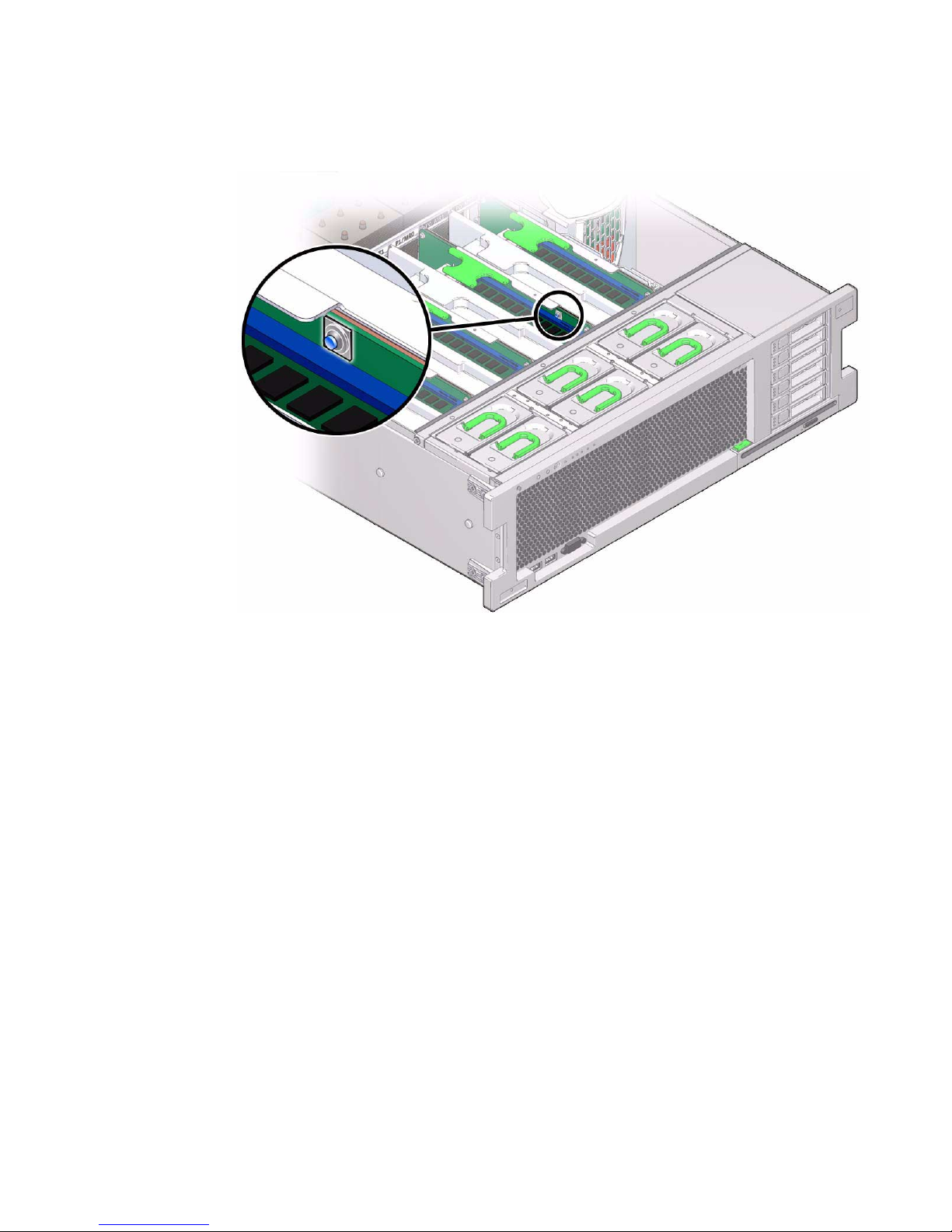
FIGURE 4-5 Fault Remind Button on Memory Riser
5. To remove the DIMM do the following (FIGURE 4-6):
a. Rotate both DIMM slot ejectors outward as far as they will go.
The DIMM is partially ejected from the socket.
b. Carefully lift the DIMM straight up to remove it from the socket.
4-12 Sun Server X2-4 Service Manual • April 2013
Page 67

FIGURE 4-6 DIMM Socket Release and Alignment
Figure Legend
1 DIMM connector slot
2 DIMM connector key
3 DIMM ejector lever
Caution – Whenever you remove a memory riser or DIMM, you should replace it
with another memory riser or a DIMM or a filler panel; otherwise, the server might
overheat due to improper airflow.
Caution – Be sure to install DIMMs in matched pairs of identical DIMM types (same
part number).
▼ Install Memory Risers and DIMMs
Refer to FIGURE 4-7 and FIGURE 4-8 when completing the following procedure.
Chapter 4 Servicing CRU Components That Require Server Power Off 4-13
Page 68

1. Unpack the DIMMs and place them on an antistatic mat.
2. Ensure that the ejector levers at both ends of the memory module slot are in a
fully open position.
3. Align the DIMM with the empty slot.
Align the notch in the DIMM with the key in the connector. The notch ensures that
the DIMM is oriented correctly.
FIGURE 4-7 Installing DIMMs
4. Gently press the DIMM into the slot until the ejector tabs lock the DIMM in
place.
If the DIMM does not easily seat into the connector, verify that the notch in the
DIMM is aligned with the key in the connector as shown in
is not aligned, damage to the DIMM might occur.
5. Repeat Step 2 through Step 4 until all replacement DIMMs are installed.
6. Push the memory riser module into the associated CPU memory riser slot until
the riser module locks in place.
4-14 Sun Server X2-4 Service Manual • April 2013
FIGURE 4-6. If the notch
Page 69

FIGURE 4-8 Installing a Memory Riser Module
7. Return the server to operation:
a. Install the top cover.
See Section 6.1 “Replacing the Server Top Cover” on page 6-1.
b. Return the server to the normal rack position.
See Section 6.2 “Returning the Server to the Normal Rack Position” on page 6-2.
c. Power on the server.
See Section 6.3 “Powering On the Server” on page 6-3.
Chapter 4 Servicing CRU Components That Require Server Power Off 4-15
Page 70

▼ Install a Memory Riser Filler Panel
1. Align the memory riser filler panel with the empty slot.
2. Gently press the memory riser filler panel into the slot.
3. Return the server to operation:
a. Install the top cover.
See Section 6.1 “Replacing the Server Top Cover” on page 6-1.
b. Return the server to the normal rack position.
See Section 6.2 “Returning the Server to the Normal Rack Position” on page 6-2.
c. Power on the server.
See Section 6.3 “Powering On the Server” on page 6-3.
▼ Install a DIMM Filler Panel
1. Locate the vacant DIMM slot on the memory riser.
2. Ensure that the ejector levers at both ends of the memory module slot are in a
fully open position.
3. Align the DIMM filler panel with the empty slot.
4. Gently press the DIMM filler panel into the slot until the ejector tabs lock the
filler panel in place.
5. Return the server to operation:
a. Install the top cover.
See Section 6.1 “Replacing the Server Top Cover” on page 6-1.
b. Return the server to the normal rack position.
See Section 6.2 “Returning the Server to the Normal Rack Position” on page 6-2.
c. Power on the server.
See Section 6.3 “Powering On the Server” on page 6-3.
4-16 Sun Server X2-4 Service Manual • April 2013
Page 71

4.2 Servicing PCIe Cards (CRU)
This section describes how to remove and install PCIe cards.
For the location of the PCIe slots, see Section 1.3 “Server Back Panel Features” on
page 1-10.
4.2.1 PCIe Card Configuration Rules
The server supports up to ten low-profile PCIe 2.0 cards. Refer to the Sun Server X2-4
Product Notes for details about supported PCIe cards, along with card quantity and
slot restrictions.
The following PCIe card slots are available on the server:
■ Slots 0 and 9: x4 electrical interface
■ Slots 1, 2, 4, 6, 7, and 8: x8 electrical interface
■ Slots 3 and 5: x8 or x16 electrical interface (x16 connector)
Note – Slots 3 and 5 operate as x16 interfaces only when an x16 capable card is
installed and the adjacent slot (4 or 6) is unpopulated.
To determine the slot in which to install a PCIe card, follow these guidelines:
■ First consider any cooling considerations that require a card to be installed in a
certain slot. For information about cooling considerations for PCIe cards, refer to
the Sun Server X2-4 Product Notes.
■ If your configuration includes an internal SAS/SATA Host Bus Adapter (HBA),
see if it has an integrated battery pack. Install a battery-backed internal HBA in
slot 4, for best cooling; otherwise, put the simpler, battery-less SAS/SATA HBA in
slot 2.
■ For high bandwidth cards, install the cards so that the load on the server is
balanced between the server ’s two I/O hubs (IOH), each of which connects to five
of the available PCIe slots. (IOH0 connects to slots 0–4 and IOH1 to slots 5–9.)
Avoid slots 9 and 0 for high-bandwidth cards since those are the x4 slots. Balance
the load as follows:
– IOH0 (which connects to slots 0–4), might already be using some bandwidth for
the ICH10 southbridge devices, so install the first high-bandwidth card in one
of slots 5–8.
Chapter 4 Servicing CRU Components That Require Server Power Off 4-17
Page 72

– Install the next high-bandwidth card in one of slots 1–4. (If an internal HBA is
already installed in slot 0–4, skip this step and install the next card in another of
slots 5–8.)
– Continue to alternate the high-bandwidth cards between slots 1–4 and 5–8.
■ Install lower-speed cards (for example, 1-Gbit/s Ethernet and 8-Gbit/s Fibre
Channel adapters) in any remaining slots, since these cards perform well in any
location, including the x4 slots, 0 and 9.
4.2.2 PCIe Cards With Bootable Devices
If the server has several PCIe cards installed that provide bootable devices, disable
the Option ROM on the PCIe slots not used for booting so that resources are
available for the slots used for booting. By default, the BIOS enables Option ROMs
for PCIe slots 2 and 4, and the four Gigabit Ethernet ports. Refer to “Configure
Option ROM Settings” on page 7-21 for information about disabling Option ROM.
4.2.3 Avoiding PCI Resource Exhaustion Errors
With several Sun x4 PCI Express Quad Gigabit Ethernet Low Profile Adapter PCIe
cards (4446A-Z-N or X4446A-Z-N) installed in server slots 0 through 4, or even one
of these cards installed in slots 5 through 9, BIOS might log a "PCI resource
exhaustion" event. This error occurs because BIOS allocates 8 Kbytes of I/O space for
each of the Quad Gigabit Ethernet cards (and only 4 Kbytes of I/O space for a typical
card).
The following is a common form of the error that might be logged:
6491 Tue Dec 7 14:19:57 2010 IPMI Log minor
ID = a5a9 : 12/07/2010 : 14:19:57 : System Firmware Error:
sensor number
=0x00 : PCI resource exhaustion: Bus 147 Device 0 Func 0
6490 Tue Dec 7 14:19:57 2010 IPMI Log minor
ID = a5a8 : 12/07/2010 : 14:19:57 : System Firmware Error:
sensor number
=0x00 : PCI resource exhaustion: Bus 147 Device 0 Func 1
To eliminate the "PCI resource exhaustion" event, change the BIOS settings to disable
I/O allocation for any slot where the Quad Gigabit Ethernet card is installed. Refer to
Section 7.8 “Performing Common BIOS Procedures” on page 7-11 for instructions on
how to access the BIOS Setup Utility in order to disable I/O allocation from the
PCIPnP menu. The exception to this workaround is that if PXE network booting will
use a Quad Gigabit Ethernet card, you should leave I/O allocation enabled for that
slot.
4-18 Sun Server X2-4 Service Manual • April 2013
Page 73

Since BIOS does not allocate I/O space for empty slots, maximizing the number of
empty PCIe slots in the server might also help to avoid the "PCI resource exhaustion"
event.
4.2.4 Removing and Installing PCIe Cards and PCIe
Card Filler Panels
Use the following procedures to remove and install PCIe cards and PCIe card filler
panels.
▼ Remove a PCIe Card Filler Panel
Caution – This procedure requires that you handle components that are sensitive to
static discharge. This sensitivity can cause the component to fail. To avoid damage,
ensure that you follow antistatic practices as described in Section 2.3 “Performing
Electrostatic Discharge and Static Prevention Measures” on page 2-3.
Caution – Ensure that all power is removed from the server before removing or
installing expansion cards. You must disconnect the power cables before performing
this procedure.
1. Prepare for servicing:
a. Attach an antistatic wrist strap.
See Section 2.3 “Performing Electrostatic Discharge and Static Prevention
Measures” on page 2-3.
b. Power off the server and disconnect all power cords from the server power
supplies.
See Section 2.6 “Powering Off the Server” on page 2-6.
c. Extend the server to the maintenance position.
See Section 2.4 “Positioning the Server for Maintenance” on page 2-4.
d. Remove the top cover.
See Section 2.7 “Removing the Server Top Cover” on page 2-8.
Chapter 4 Servicing CRU Components That Require Server Power Off 4-19
Page 74

2. Locate the PCIe card filler panel that you want to remove.
See Section 1.3 “Server Back Panel Features” on page 1-10 for information about
PCIe slots and their locations.
3. Disengage the PCIe slot crossbar from its locked position and rotate the
crossbar into an upright position (
4. Remove the PCIe card filler panel from the PCIe slot.
FIGURE 4-9).
Caution – Whenever you remove a PCIe card filler panel, you should replace it with
another filler panel or a PCIe card; otherwise, the server might overheat due to
improper airflow.
▼ Remove a PCIe Card
Caution – This procedure requires that you handle components that are sensitive to
static discharge. This sensitivity can cause the component to fail. To avoid damage,
ensure that you follow antistatic practices as described in Section 2.3 “Performing
Electrostatic Discharge and Static Prevention Measures” on page 2-3.
Caution – Ensure that all power is removed from the server before removing or
installing expansion cards. You must disconnect the power cables before performing
this procedure.
1. Prepare for servicing:
a. Attach an antistatic wrist strap.
See Section 2.3 “Performing Electrostatic Discharge and Static Prevention
Measures” on page 2-3.
b. Power off the server and disconnect all power cords from the server power
supplies.
See Section 2.6 “Powering Off the Server” on page 2-6.
c. Extend the server to the maintenance position.
See Section 2.4 “Positioning the Server for Maintenance” on page 2-4.
d. Remove the top cover.
See Section 2.7 “Removing the Server Top Cover” on page 2-8.
4-20 Sun Server X2-4 Service Manual • April 2013
Page 75

2. Locate the PCIe card that you want to remove.
See Section 1.3 “Server Back Panel Features” on page 1-10 for information about
PCIe slots and their locations.
3. If necessary, make a note of where the PCIe cards are installed.
4. Unplug all data cables from the PCIe card.
Note the location of all cables for reinstallation later.
5. Disengage the PCIe card slot crossbar from its locked position and rotate the
crossbar into an upright position (
FIGURE 4-9).
6. Carefully remove the PCIe card from the PCIe card slot.
FIGURE 4-9 Disengaging the Crossbar
Caution – Whenever you remove a PCIe card, you should replace it with another
PCIe card or a filler panel; otherwise, the server might overheat due to improper
airflow.
Chapter 4 Servicing CRU Components That Require Server Power Off 4-21
Page 76
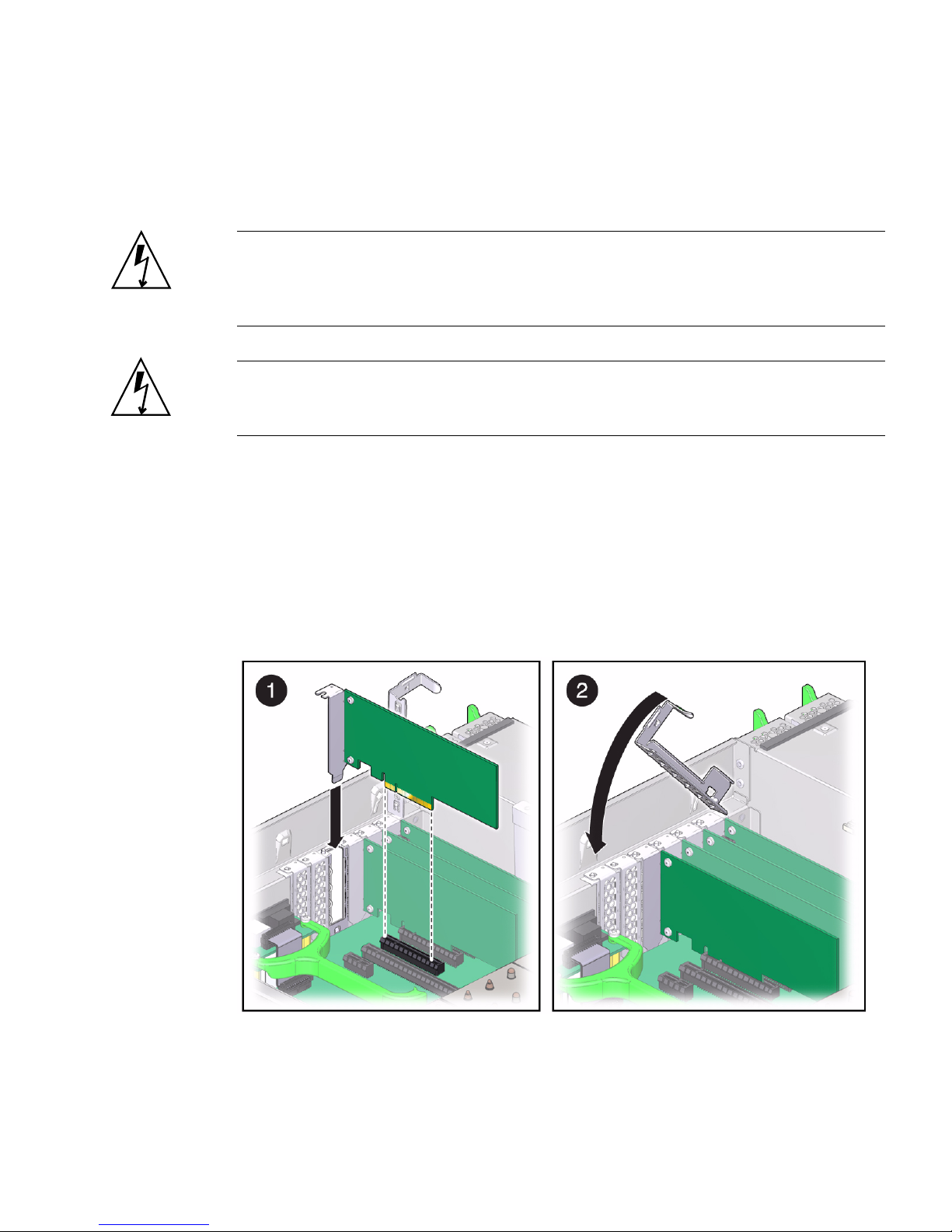
▼ Install a PCIe Card
Refer to FIGURE 4-10 when completing the following procedure.
Caution – This procedure requires that you handle components that are sensitive to
static discharge. This sensitivity can cause the component to fail. To avoid damage,
ensure that you follow antistatic practices as described in Section 2.3 “Performing
Electrostatic Discharge and Static Prevention Measures” on page 2-3.
Caution – Ensure that all power is removed from the server before removing or
installing PCIe cards. You must disconnect the power cables before performing this
procedure.
1. Unpack the PCIe card and place it on an antistatic mat.
2. Ensure that the server is powered off and all power cords are disconnected from
the server power supplies.
See Section 2.6 “Powering Off the Server” on page 2-6.
3. Install the PCIe card into the PCIe card slot.
FIGURE 4-10 Installing a PCIe Card
4. Return the PCIe card slot crossbar to its closed and locked position.
5. Return the server to operation:
4-22 Sun Server X2-4 Service Manual • April 2013
Page 77

a. Install the top cover.
See Section 6.1 “Replacing the Server Top Cover” on page 6-1.
b. Return the server to the normal rack position.
See Section 6.2 “Returning the Server to the Normal Rack Position” on page 6-2.
c. Reconnect all power cords to the server power supplies and power on the
server.
See Section 6.3 “Powering On the Server” on page 6-3.
6. If the PCIe card being installed is replacing a faulty PCIe card, manually clear
the PCIe card fault using Oracle Integrated Lights Out Manager (ILOM).
For instructions on clearing server faults, refer to the Oracle Integrated Lights Out
Manager (ILOM) 3.1 User ’s Guide.
7. Refer to the documentation shipped with the PCIe card for information about
configuring the PCIe card, including installing required operating systems.
To create or recover RAID configurations, refer to the LSI MegaRAID SAS Software
User’s Guide, which is available at the following location:
http://www.lsi.com/support/sun
▼ Install a PCIe Card Filler Panel
Refer to FIGURE 4-10 when completing the following procedure.
Caution – This procedure requires that you handle components that are sensitive to
static discharge. This sensitivity can cause the component to fail. To avoid damage,
ensure that you follow antistatic practices as described in Section 2.3 “Performing
Electrostatic Discharge and Static Prevention Measures” on page 2-3.
Caution – Ensure that all power is removed from the server before removing or
installing PCIe card filler panels. You must disconnect the power cables before
performing this procedure.
1. Ensure that the server is powered off and all power cords are disconnected from
the server power supplies.
See Section 2.6 “Powering Off the Server” on page 2-6.
2. Install the PCIe card filler panel into the PCIe card slot.
3. Return the PCIe card slot crossbar to its closed and locked position.
Chapter 4 Servicing CRU Components That Require Server Power Off 4-23
Page 78

4. Return the server to operation:
a. Install the top cover.
See Section 6.1 “Replacing the Server Top Cover” on page 6-1.
b. Return the server to the normal rack position.
See Section 6.2 “Returning the Server to the Normal Rack Position” on page 6-2.
c. Reconnect all power cords to the server power supplies and power on the
server.
See Section 6.3 “Powering On the Server” on page 6-3.
4.3 Servicing the DVD Drive and DVD
Driver Filler Panel (CRU)
Use the following procedures to remove and replace the DVD drive and DVD drive
filler panel.
▼ Remove the DVD Drive or DVD Drive Filler
Panel
Refer to FIGURE 4-11 when completing the following procedure.
1. Prepare for servicing:
a. Attach an antistatic wrist strap.
See Section 2.3 “Performing Electrostatic Discharge and Static Prevention
Measures” on page 2-3.
b. Remove any media from the drive.
c. Power off the server.
See Section 2.6 “Powering Off the Server” on page 2-6.
2. Push down on the latch on the top left corner of the DVD drive or filler panel.
3. Slide the DVD drive or filler panel out of the server.
4-24 Sun Server X2-4 Service Manual • April 2013
Page 79

Caution – Whenever you remove the DVD drive or filler panel, you should replace
it with another DVD drive or a filler panel; otherwise the server might overheat due
to improper airflow.
FIGURE 4-11 Removing the DVD Drive or Filler Panel
▼ Install the DVD Drive or DVD Drive Filler Panel
Refer to FIGURE 4-12 when completing the following procedure.
1. Unpack the DVD drive or filler panel.
If it is a DVD drive, place it on an antistatic mat.
2. Slide the DVD drive or filler panel into the front of the chassis until it seats.
Chapter 4 Servicing CRU Components That Require Server Power Off 4-25
Page 80
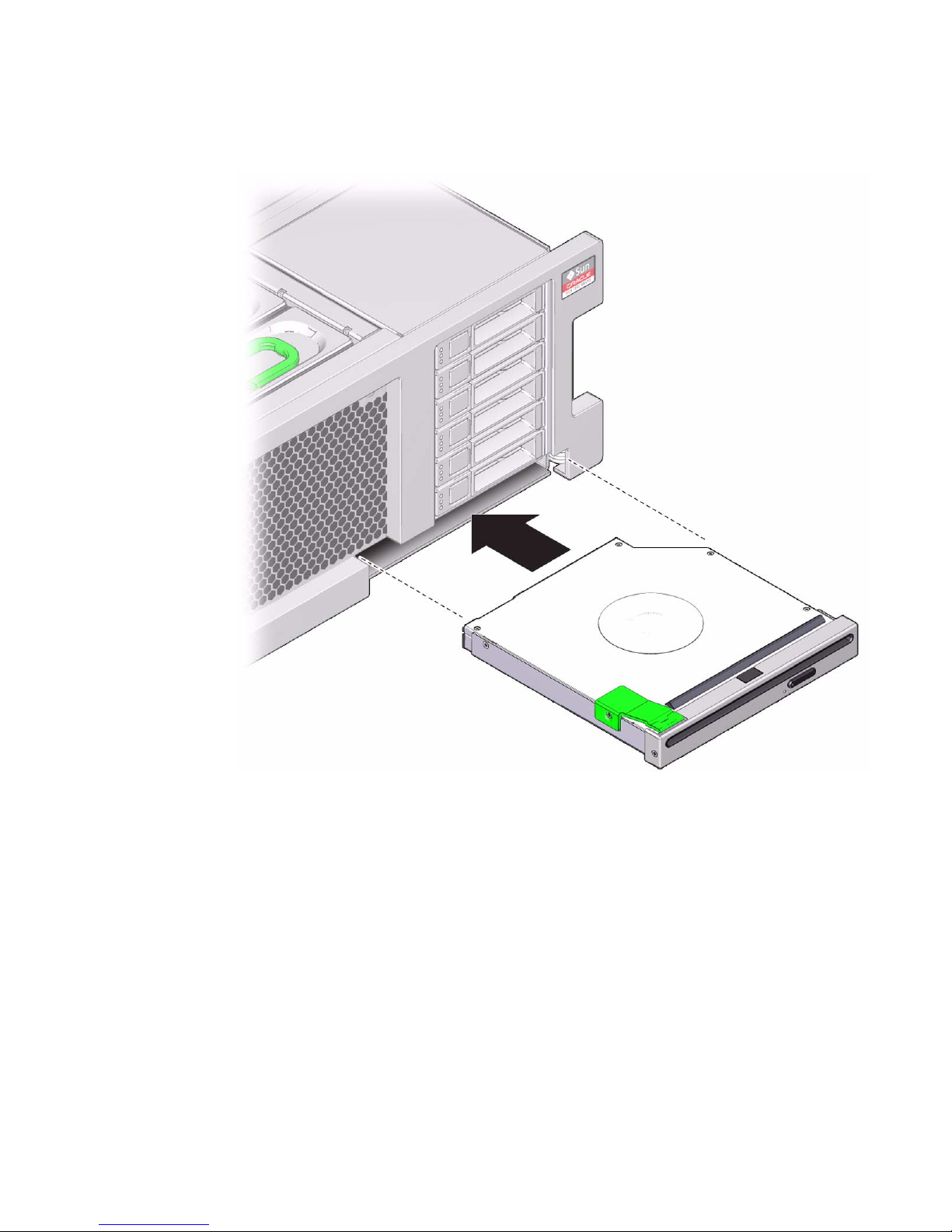
FIGURE 4-12 Installing the DVD Drive or Filler Panel
3. Return the server to operation:
a. Return the server to the normal rack position.
See Section 6.2 “Returning the Server to the Normal Rack Position” on page 6-2.
b. Power on the server.
See Section 6.3 “Powering On the Server” on page 6-3.
4-26 Sun Server X2-4 Service Manual • April 2013
Page 81
4.4 Servicing the System Lithium Battery
(CRU)
The system battery maintains system time when the server is powered off and
disconnected from AC power. If the IPMI logs indicate a battery failure, you should
replace the system battery. Use the following procedures to remove and replace the
system battery.
Caution – Ensure that all power is removed from the server before removing or
installing the battery. You must disconnect the power cables from the system before
performing these procedures.
▼ Remove the System Battery
1. Prepare for servicing:
a. Attach an antistatic wrist strap.
See Section 2.3 “Performing Electrostatic Discharge and Static Prevention
Measures” on page 2-3.
b. Power off the server and disconnect all power cords from the server power
supplies.
See Section 2.6 “Powering Off the Server” on page 2-6.
c. Extend the server to the maintenance position.
See Section 2.4 “Positioning the Server for Maintenance” on page 2-4.
d. Remove the top cover.
See Section 2.7 “Removing the Server Top Cover” on page 2-8.
2. Remove the battery from the battery holder by pulling back on the metal tab
holding it in place and sliding the battery up and out of the battery holder
(
FIGURE 4-13).
Chapter 4 Servicing CRU Components That Require Server Power Off 4-27
Page 82

FIGURE 4-13 Removing the Battery
▼ Install the System Battery
1. Unpackage the replacement battery.
2. Press the new battery into the battery holder with the positive side (+) facing
away from the metal tab that holds it in place.
3. If the service processor is configured to synchronize with a network time server
using the Network Time Protocol (NTP), the Oracle ILOM clock will be reset as
soon as the server is powered on and connected to the network. Otherwise,
proceed to the next step.
4. If the service processor is not configured to use NTP, you must reset the Oracle
ILOM clock using the Oracle ILOM CLI or the web interface.
For instructions, see the Oracle Integrated Lights Out Manager (ILOM) 3.1
Documentation Library at
http://www.oracle.com/pls/topic/lookup?ctx=ilom31
5. Return the server to operation:
4-28 Sun Server X2-4 Service Manual • April 2013
Page 83

a. Install the top cover.
See Section 6.1 “Replacing the Server Top Cover” on page 6-1.
b. Return the server to the normal rack position.
See Section 6.2 “Returning the Server to the Normal Rack Position” on page 6-2.
c. Reconnect all power cords to the server power supplies and power on the
server.
See Section 6.3 “Powering On the Server” on page 6-3.
6. After the battery is replaced, use the BIOS Setup Utility to update the System
Time and System Date.
Refer to Chapter 7 for information about using the BIOS Setup Utility.
Chapter 4 Servicing CRU Components That Require Server Power Off 4-29
Page 84

4-30 Sun Server X2-4 Service Manual • April 2013
Page 85

CHAPTER
5
Servicing FRU Components
This chapter describes how to service field-replaceable units (FRUs). You must power
down the system and remove the AC power cords before servicing all FRU
components.
Note – Only authorized service providers (ASPs) should service FRU components.
This chapter contains the following topics:
■ Section 5.1 “Servicing the CPU and Heatsink (FRU)” on page 5-1
■ Section 5.2 “Servicing the Fan Board (FRU)” on page 5-8
■ Section 5.3 “Servicing the Power Supply Backplane (FRU)” on page 5-12
■ Section 5.4 “Servicing the Disk Drive Backplane (FRU)” on page 5-15
■ Section 5.5 “Servicing the Motherboard (FRU)” on page 5-19
5.1 Servicing the CPU and Heatsink (FRU)
This section describes how to service the CPU and heatsink.
Caution – These procedures require that you handle components that are sensitive
to static discharge. This sensitivity can cause the component to fail. To avoid damage,
ensure that you follow antistatic practices as described in Section 2.3 “Performing
Electrostatic Discharge and Static Prevention Measures” on page 2-3.
5-1
Page 86

5.1.1 CPU Placement
The server operates with either two or four CPUs. In a two-CPU system, the CPUs
must be installed in sockets 0 and 2.
5.1.2 Removing and Installing a Heatsink Filler Panel,
CPU Cover Plate, Heatsink, and CPU
Use the following procedures to remove and install a heatsink filler panel, a CPU
cover plate, a heatsink, and a CPU.
Note – When installing a CPU, you must also remove the heatsink or heatsink filler
panel on the CPU to the left (facing toward the front of the chassis) of the one to be
installed so that the CPU release lever has room to properly disengage.
▼ Remove a Heatsink Filler Panel and CPU Cover Plate
1. Prepare for servicing:
a. Attach an antistatic wrist strap.
See Section 2.3 “Performing Electrostatic Discharge and Static Prevention
Measures” on page 2-3.
b. Power off the server completely and disconnect all power cords from the
server power supplies.
See Section 2.6 “Powering Off the Server” on page 2-6.
c. Extend the server to the maintenance position.
See Section 2.4 “Positioning the Server for Maintenance” on page 2-4.
d. Remove the top cover.
See Section 2.7 “Removing the Server Top Cover” on page 2-8.
2. Loosen the two captive screws holding the heatsink filler panel in place.
3. Lift the heatsink filler panel out of the chassis.
Caution – Whenever you remove a heatsink filler panel, you should replace it with
a heatsink or another heatsink filler panel; otherwise, the server might overheat due
to improper airflow.
5-2 Sun Server X2-4 Service Manual • April 2013
Page 87

4. If you are installing a CPU into a CPU socket where a CPU has never been
installed, remove the CPU cover plate:
a. Disengage the CPU release lever by pushing down and moving it to the side
away from the CPU socket, and then rotating the lever upward.
b. Open the load plate and carefully remove the CPU cover plate.
▼ Remove a Heatsink and CPU
Refer to FIGURE 5-1 and FIGURE 5-2 when completing the following procedure.
1. Prepare for servicing:
a. Attach an antistatic wrist strap.
See Section 2.3 “Performing Electrostatic Discharge and Static Prevention
Measures” on page 2-3.
b. Power off the server completely and disconnect all power cords from the
server power supplies.
See Section 2.6 “Powering Off the Server” on page 2-6.
c. Extend the server to the maintenance position.
See Section 2.4 “Positioning the Server for Maintenance” on page 2-4.
d. Remove the top cover.
See Section 2.7 “Removing the Server Top Cover” on page 2-8.
2. If necessary, identify the location of the faulty CPU by pressing the Fault
Remind button on the air divider.
■ If the CPU LED behind the CPU on the motherboard is off: CPU is operating
properly.
■ If the CPU LED behind the CPU on the motherboard is on (amber): CPU is
faulty and should be replaced.
Note – Located above the Fault Remind button is the Fault Remind button Power
LED. When the Fault Remind button is pressed, the Power LED illuminates (green)
to indicate that the remind circuitry is working correctly.
Chapter 5 Servicing FRU Components 5-3
Page 88

FIGURE 5-1 Fault Remind Button on Air Divider
3. Remove the heatsink:
a. Unscrew the two Phillips screws from the heatsink.
Turn the screws alternately one and one half turns until they are fully removed.
b. Twist the heatsink slightly to break the grease seal, lift off the heatsink and
place it upside down on a flat surface to prevent the thermal grease from
contaminating other components.
c. Use an alcohol pad to clean the thermal grease from both the bottom of the
heatsink and the top of the CPU.
Caution – Whenever you remove a heatsink, you should replace it with another
heatsink or a filler panel; otherwise, the server might overheat due to improper
airflow.
Caution – Failure to clean the heatsink and the CPU prior to removing the CPU
could result in accidental contamination of the CPU socket or other components.
Also, be careful not to get the grease on your fingers as this could result in
contamination of components.
4. If you are replacing the CPU as well as the heatsink, remove the CPU:
5-4 Sun Server X2-4 Service Manual • April 2013
Page 89

a. Disengage the CPU release lever by pushing down and moving it to the side
away from the CPU, and then rotating the lever upward.
b. Open the load plate and carefully remove the CPU.
FIGURE 5-2 Removing the Heatsink and CPU
▼ Install a Heatsink and CPU
1. Unpack the installation kit.
Depending on whether you are adding a new CPU and heatsink, or replacing one
or both of these components because they are damaged, your kit might contain the
following:
■ CPU and pre-greased heatsink
■ Pre-greased heatsink only
■ CPU only, with syringe to apply thermal grease to existing heatsink
2. If applicable, install the CPU (
FIGURE 5-3).
Chapter 5 Servicing FRU Components 5-5
Page 90

a. Properly orient the CPU with the socket alignment tabs and carefully place
the CPU into the socket.
Ensure that the orientation is correct as damage might result if the CPU pins are
not aligned correctly.
FIGURE 5-3 Installing the CPU
b. Lower the load plate.
Ensure that the load plate sits flat around the periphery of the CPU.
c. Engage the release lever by rotating it downward and slipping it under the
catch.
3. Install the heatsink.
5-6 Sun Server X2-4 Service Manual • April 2013
Page 91

a. If you are reusing an existing cleaned heatsink, use the syringe (supplied
with the new or replacement CPU) to apply thermal grease on top of the CPU
in a star pattern.
Note – You do not need to complete this step if you have a new heatsink since new
heatsinks come with thermal grease already applied.
b. Orient the heatsink so that the two screws line up with the mounting studs.
Caution – When handling the heatsink, be careful not to get the thermal grease on
your fingers so as not to transfer the grease to other server components. To do so
could cause component contamination and/or damage.
c. Carefully position the heatsink on the CPU, aligning it with the mounting
posts to reduce movement after it makes initial contact with the layer of
thermal grease.
Caution – If the heatsink assembly is moved too much during its installation, the
layer of thermal grease might not be distributed evenly, leading to component
damage.
d. Tighten the screws alternately one-half turn until fully seated.
4. Return the server to operation:
a. Install the top cover.
See Section 6.1 “Replacing the Server Top Cover” on page 6-1.
b. Return the server to the normal rack position.
See Section 6.2 “Returning the Server to the Normal Rack Position” on page 6-2.
c. Reconnect all power cords to the server power supplies and power on the
server.
See Section 6.3 “Powering On the Server” on page 6-3.
5. If the CPU being installed is replacing a faulty CPU, manually clear the CPU
fault using Oracle ILOM.
For instructions on clearing server faults, refer to the Oracle Integrated Lights Out
Manager (ILOM) 3.1 Users Guide.
Chapter 5 Servicing FRU Components 5-7
Page 92
▼ Install a Heatsink Filler Panel
1. Orient the heatsink filler panel so that the two captive screws line up with the
mounting studs.
2. Carefully position the heatsink filler panel on top of the CPU socket.
3. Tighten the two captive screws to secure the heatsink filler panel.
4. Return the server to operation:
a. Install the top cover.
See Section 6.1 “Replacing the Server Top Cover” on page 6-1.
b. Return the server to the normal rack position.
See Section 6.2 “Returning the Server to the Normal Rack Position” on page 6-2.
c. Power on the server.
See Section 6.3 “Powering On the Server” on page 6-3.
5.2 Servicing the Fan Board (FRU)
Use the following procedures to remove and install the fan board.
Caution – These procedures require that you handle components that are sensitive
to static discharge. This sensitivity can cause the component to fail. To avoid damage,
ensure that you follow antistatic practices as described in Section 2.3 “Performing
Electrostatic Discharge and Static Prevention Measures” on page 2-3.
▼ Remove the Fan Board
1. Prepare for servicing:
a. Attach an antistatic wrist strap.
See Section 2.3 “Performing Electrostatic Discharge and Static Prevention
Measures” on page 2-3.
b. Power off the server completely and disconnect all power cords from the
server power supplies.
See Section 2.6 “Powering Off the Server” on page 2-6.
5-8 Sun Server X2-4 Service Manual • April 2013
Page 93

c. Extend the server to the maintenance position.
See Section 2.4 “Positioning the Server for Maintenance” on page 2-4.
d. Remove the top cover.
See Section 2.7 “Removing the Server Top Cover” on page 2-8.
2. Remove all fan modules.
See “Remove a Fan Module” on page 3-8.
3. Remove all memory risers.
See “Remove a Memory Riser and DIMM” on page 4-9.
4. Disconnect any cables plugged into the USB or video connectors on the front of
the server.
5. Remove the fan board (
FIGURE 5-4):
a. Loosen the three captive screws connecting the front memory riser guide to
the motherboard.
b. Remove the two screws on each side of the outside of the chassis that hold
the fan board unit in place.
c. Unplug the fan board cable and power cables from motherboard.
d. Remove the front memory riser guide by pulling it up and out of the chassis.
e. Pull the fan board back and out of chassis.
Chapter 5 Servicing FRU Components 5-9
Page 94

FIGURE 5-4 Removing the Fan Board
▼ Install the Fan Board
1. Unpack the replacement fan board unit and place it on an antistatic mat.
2. Remove the fan board cable and power cables from the faulty fan board unit
and plug them into the fan board on the replacement fan board unit.
3. Reinstall the fan board unit (
a. Insert the fan board unit into the chassis, moving it down and toward the
front.
b. Reposition the front memory riser guide, routing the fan board and power
cable through the riser guide.
c. Plug the fan board cable and power cable into the connectors on the
motherboard.
5-10 Sun Server X2-4 Service Manual • April 2013
FIGURE 5-5):
Page 95

d. Tighten the three captive screws to hold the front memory riser guide in
place.
e. Secure the fan board unit in place by reinserting and tightening the two
screws on each side of the outside of the chassis.
FIGURE 5-5 Installing the Fan Board
4. Reinstall all fan modules.
See “Install a Fan Module” on page 3-9.
5. Reinstall all memory risers.
See “Install Memory Risers and DIMMs” on page 4-13.
6. Return the server to operation:
a. Install the top cover.
See Section 6.1 “Replacing the Server Top Cover” on page 6-1.
b. Return the server to the normal rack position.
See Section 6.2 “Returning the Server to the Normal Rack Position” on page 6-2.
Chapter 5 Servicing FRU Components 5-11
Page 96

c. Reconnect all power cords to the server power supplies and power on the
server.
See Section 6.3 “Powering On the Server” on page 6-3.
Note – The product serial number used for service entitlement and warranty
coverage might need to be reprogrammed on the fan board by authorized service
personnel with the correct product serial number located on the chassis EZ label.
5.3 Servicing the Power Supply Backplane
(FRU)
Use the following procedures to remove and install the power supply backplane.
Caution – The system supplies power to the power board even when the server is
powered off. To avoid personal injury or damage to the server, you must disconnect
power cords before servicing the power distribution board.
▼ Remove the Power Supply Backplane
Refer to FIGURE 5-6 when completing the following procedure.
1. Prepare for servicing:
a. Attach an antistatic wrist strap.
See Section 2.3 “Performing Electrostatic Discharge and Static Prevention
Measures” on page 2-3.
b. Power off the server completely and disconnect all power cords from the
server power supplies.
See Section 2.6 “Powering Off the Server” on page 2-6.
c. Extend the server to the maintenance position.
See Section 2.4 “Positioning the Server for Maintenance” on page 2-4.
d. Remove the top cover.
See Section 2.7 “Removing the Server Top Cover” on page 2-8.
5-12 Sun Server X2-4 Service Manual • April 2013
Page 97

2. Pull both power supplies at least part way out of the chassis, to disconnect them
from the power supply backplane.
See “Remove a Power Supply” on page 3-13.
3. Remove the memory riser or filler panel closest to the air divider.
See Section 4.1.8 “Removing and Installing Memory Risers, DIMMs, and Filler
Panels” on page 4-8.
4. Remove the air divider by pulling it up and out of the chassis.
5. Remove the ribbon cable connecting the power supply backplane to the
motherboard.
6. Remove the screw holding the power supply cover in place and remove the
power supply cover (Step 1 in
FIGURE 5-6).
7. Remove the motherboard.
See “Remove the Motherboard” on page 5-19. The motherboard removal
procedure involves removing the four bus bar screws that secure the motherboard
to the power supply backplane, as shown in Step 2 in
FIGURE 5-6.
8. Disconnect the AC cables from power supply backplane.
9. Lift the power supply backplane out of the chassis (Step 3 in
FIGURE 5-6 Removing Power Supply Backplane
FIGURE 5-6).
Chapter 5 Servicing FRU Components 5-13
Page 98

▼ Install the Power Supply Backplane
Refer to FIGURE 5-7 when completing the following procedure.
1. Unpack the replacement power supply backplane and place it on an antistatic
mat.
2. Hold the power supply backplane at the end of the power supply cage and
connect the AC cables to the AC connectors on the power supply backplane.
Ensure that each AC cable is connected to the appropriate connector. The AC cable
on the right must be connected to the AC connector on the right and the AC cable
on the left must be connected to the AC connector on the left.
3. Insert the power supply backplane into position by ensuring that the tabs on
the power board slide onto the hooks on the power supply cage (Step 1 in
FIGURE 5-7).
4. Install the motherboard.
See “Install the Motherboard” on page 5-20. The motherboard installation
procedure involves reinserting and tightening the four bus bar screws that secure
the motherboard to the power supply backplane, as shown in Step 2 in
5. Replace the power supply cover and fasten it in place with the screw (Step 3 in
FIGURE 5-7).
FIGURE 5-7.
6. Reconnect the ribbon cable from the motherboard to the power supply
backplane.
7. Reinstall the air divider by sliding it into the chassis.
8. Reinstall the memory riser or filler panel closest to the air divider.
See Section 4.1.8 “Removing and Installing Memory Risers, DIMMs, and Filler
Panels” on page 4-8.
5-14 Sun Server X2-4 Service Manual • April 2013
Page 99

FIGURE 5-7 Installing the Power Supply Backplane
9. Push the power supplies all the way back into the chassis.
See “Install a Power Supply” on page 3-14.
10. Return the server to operation:
a. Install the top cover.
See Section 6.1 “Replacing the Server Top Cover” on page 6-1.
b. Return the server to the normal rack position.
See Section 6.2 “Returning the Server to the Normal Rack Position” on page 6-2.
c. Reconnect all power cords to the server power supplies and power on the
server.
See Section 6.3 “Powering On the Server” on page 6-3.
5.4 Servicing the Disk Drive Backplane
(FRU)
Use the following procedures to remove and install the disk drive backplane.
Chapter 5 Servicing FRU Components 5-15
Page 100

Caution – These procedures require that you handle components that are sensitive
to static discharge. This sensitivity can cause the component to fail. To avoid damage,
ensure that you follow antistatic practices as described in Section 2.3 “Performing
Electrostatic Discharge and Static Prevention Measures” on page 2-3.
▼ Remove the Disk Drive Backplane
Refer to FIGURE 5-8 when completing the following procedure.
1. Prepare for servicing:
a. Attach an antistatic wrist strap.
See Section 2.3 “Performing Electrostatic Discharge and Static Prevention
Measures” on page 2-3.
b. Power off the server completely and disconnect all power cords from the
power supplies.
See Section 2.6 “Powering Off the Server” on page 2-6.
c. Extend the server to the maintenance position.
See Section 2.4 “Positioning the Server for Maintenance” on page 2-4.
d. Remove the top cover.
See Section 2.7 “Removing the Server Top Cover” on page 2-8.
2. Remove all disk drives and fillers.
See “Remove a Disk Drive” on page 3-3.
3. Remove the DVD drive.
See “Remove the DVD Drive or DVD Drive Filler Panel” on page 4-24.
4. Remove power cable, ribbon data cable, and any SAS/SATA cables from the
disk drive backplane.
5. Push up on the wire tab in the upper corner and pull the disk drive backplane
up and out of the chassis.
5-16 Sun Server X2-4 Service Manual • April 2013
 Loading...