


Sun Netra T5440 Server
Installation Guide
Part No.: E23168-01
May 2011, Revision A

Copyright ©2008, 2011 Oracleand/or itsaffiliates. Allrights reserved.
This softwareand related documentation are providedunder alicense agreement containing restrictions onuse anddisclosure andare protected by
intellectual propertylaws. Exceptas expressly permitted in your license agreementor allowedby law, you may not use, copy, reproduce,translate,
broadcast, modify,license, transmit,distribute, exhibit,perform, publish,or displayany part,in anyform, orby anymeans. Reverseengineering,
disassembly, or decompilation of this software,unless required by law for interoperability, isprohibited.
The informationcontained hereinis subjectto changewithout noticeand isnot warrantedto beerror-free.If youfind anyerrors, please report them to us
in writing.
If thisis softwareor related softwaredocumentation thatis deliveredto theU.S. Governmentor anyonelicensing iton behalfof theU.S. Government,the
following noticeis applicable:
U.S. GOVERNMENTRIGHTS Programs,software, databases, and related documentation and technical data deliveredto U.S.Government customersare
"commercial computersoftware" or "commercial technical data" pursuant to the applicable Federal Acquisition Regulation and agency-specific
supplemental regulations.As such,the use,duplication, disclosure, modification, and adaptation shall be subject to the restrictionsand licenseterms set
forth inthe applicableGovernment contract,and, tothe extentapplicable bythe termsof theGovernment contract,the additionalrights setforth inFAR
52.227-19, CommercialComputer Software License (December 2007). Oracle USA, Inc., 500 Oracle Parkway, Redwood City, CA 94065.
This software or hardware isdeveloped for general use in a variety of informationmanagement applications.It is not developed or intended for use inany
inherently dangerous applications, including applications which may create arisk ofpersonal injury. If you use this software orhardware in dangerous
applications, thenyou shallbe responsibleto takeall appropriate fail-safe, backup, redundancy, and other measures toensure the safe use. Oracle
Corporation andits affiliatesdisclaim anyliability forany damagescaused byuse ofthis software or hardware indangerous applications.
Oracle andJava areregistered trademarks of Oracle and/or its affiliates.Other namesmay betrademarks oftheir respective owners.
AMD, Opteron,the AMDlogo, andthe AMDOpteron logo are trademarks or registered trademarks of Advanced Micro Devices. Intel and Intel Xeon are
trademarks orregistered trademarks of Intel Corporation. All SPARC trademarksare used under license and are trademarks or registered trademarks of
SPARC International, Inc. UNIX is a registered trademarklicensed through X/Open Company, Ltd.
This software or hardware and documentation may provide access to or information on content, products, and services from third parties. Oracle
Corporation and its affiliates are not responsible for and expressly disclaim all warranties of any kind with respect to third-party content, products, and
services. Oracle Corporation and its affiliates will not be responsible for any loss, costs, or damages incurred due to your access to or use of third-party
content, products, or services.
Copyright ©2008, 2011, Oracleet/ou sesaffiliés. Tous droits réservés.
Ce logicielet ladocumentation quil’accompagne sontprotégés parles loissur lapropriété intellectuelle. Ils sont concédés sous licence et soumis à des
restrictions d’utilisationet dedivulgation. Saufdisposition devotre contrat de licence ou de la loi, vous ne pouvez pas copier, reproduire, traduire,
diffuser, modifier, breveter, transmettre, distribuer, exposer, exécuter, publier ou afficher le logiciel, même partiellement, sous quelque forme et par
quelque procédéque cesoit. Parailleurs, ilest interdit de procéder àtoute ingénierieinverse dulogiciel, dele désassemblerou dele décompiler, exceptéà
des finsd’interopérabilité avecdes logicielstiers outel queprescrit par la loi.
Les informationsfournies dansce documentsont susceptiblesde modificationsans préavis.Par ailleurs,Oracle Corporationne garantitpas qu’elles
soient exemptesd’erreurs etvous invite,le caséchéant, àlui enfaire part par écrit.
Si celogiciel, oula documentationqui l’accompagne,est concédésous licenceau Gouvernementdes Etats-Unis,ou àtoute entitéqui délivrela licencede
ce logicielou l’utilisepour lecompte duGouvernement desEtats-Unis, lanotice suivantes’applique :
U.S. GOVERNMENTRIGHTS. Programs,software, databases, and related documentation and technical data deliveredto U.S.Government customers
are "commercial computer software" or"commercial technicaldata" pursuantto theapplicable FederalAcquisition Regulationand agency-specific
supplemental regulations. As such, theuse, duplication,disclosure, modification, and adaptation shall be subject to the restrictions and license terms set
forth inthe applicableGovernment contract,and, tothe extentapplicable bythe termsof theGovernment contract,the additionalrights setforth inFAR
52.227-19, CommercialComputer Software License (December 2007). Oracle America, Inc., 500 Oracle Parkway, Redwood City, CA 94065.
Ce logicielou matériela étédéveloppé pourun usagegénéral dansle cadred’applications degestion desinformations. Celogiciel oumatériel n’estpas
conçu nin’est destinéà êtreutilisé dansdes applicationsà risque,notamment dansdes applicationspouvant causerdes dommagescorporels. Si vous
utilisez celogiciel oumatériel dansle cadred’applications dangereuses, il est de votre responsabilitéde prendre toutesles mesuresde secours,de
sauvegarde, deredondance et autres mesures nécessaires à son utilisation dans des conditions optimales de sécurité. Oracle Corporation et ses affiliés
déclinent touteresponsabilité quantaux dommagescausés parl’utilisation dece logicielou matérielpour cetype d’applications.
Oracle etJava sontdes marquesdéposées d’OracleCorporation et/oude sesaffiliés.Tout autre nom mentionné peut correspondre àdes marques
appartenant àd’autres propriétaires qu’Oracle.
AMD, Opteron,le logoAMD etle logoAMD Opteron sont des marquesou desmarques déposéesd’Advanced Micro Devices. Intel et Intel Xeon sont des
marques oudes marques déposées d’Intel Corporation. Toutesles marques SPARC sontutilisées souslicence etsont desmarques ou des marques
déposées deSPARC International, Inc. UNIX est une marque déposée concédée sous licence par X/Open Company, Ltd.
Ce logicielou matérielet ladocumentation quil’accompagne peuventfournir desinformations oudes liensdonnant accèsà descontenus, desproduits et
des servicesémanant detiers. OracleCorporation etses affiliésdéclinent touteresponsabilité ou garantie expresse quant aux contenus, produits ou
services émanantde tiers.En aucuncas, OracleCorporation etses affiliésne sauraientêtre tenus pour responsables des pertes subies, des coûts
occasionnés oudes dommagescausés parl’accès àdes contenus,produits ouservices tiers,ou àleur utilisation.

Contents
Preface ix
1. Sun Netra T5440 Features Overview 1
Features at a Glance 2
PCIe, PCI-X, and XAUI Card Features 4
PCI Cards on the PCI Auxilliary Board 4
PCI Cards on the PCI Mezzanine Assembly 5
High Bandwidth PCIe Card Installation 5
Chassis Overview 5
Infrastructure Boards 5
System Cables 7
Front Panel 7
Issue With Opening the Front Bezel 7
Front Panel Component Access 8
Front Panel LEDs 10
Rear Panel 11
Rear Panel Component Access 12
Rear Panel LEDs 13
Additional Feature Information 14
Chip-Multithreaded Processor and Memory Technology 14
iii

Performance Enhancements 15
Preinstalled Solaris Operating System 15
Hardware-Assisted Cryptography 16
Support for Virtualization Through
Logical Domains 16
Remote Manageability With ILOM 17
High Levels of System Reliability, Availability, and Serviceability 18
Hot-Pluggable and Hot-Swappable Components 18
Environmental Monitoring 19
Support for RAID Storage Configurations 19
Error Correction and Parity Checking 20
Fault Management and Predictive Self Healing 20
Rackmountable Enclosure 20
2. Preparing for Installation 21
Power Redundancy and Requirements 21
Changing Sun Netra Rack Servers from AC to DC Input or From DC to AC
Input 22
Additional Power System Information 22
Tools and Equipment Needed 23
Shipping Kit Inventory List 23
Optional Component Installation 24
ESD Precautions 24
Installation Overview 24
Safety Precautions 26
3. Installing a Sun Netra T5440 Server Into a Rack 29
Rackmounting Options 30
Hardmounting the Server in a 19-Inch 4-Post Rack 30
▼ To Hardmount in a 19-Inch 4-Post Rack 31
iv Sun Netra T5440 Server Installation Guide • May 2011

Mounting the Server in a Sliding Rail 19-Inch 4-Post Rack 35
▼ Mounting the Server in a 19-Inch 4-Post Rack With Sliding Rails 37
▼ To Install the Long Bracket Extenders 45
Hardmounting the Server in a 600 mm 4-Post Rack 47
▼ To Hardmount the Server in a 600 mm 4-Post Rack 48
Hardmounting the Server in a 23-Inch 2-Post Rack 53
▼ To Hardmount the Server in a 23-Inch 2-Post Rack 54
Hardmounting the Server in a 19-Inch 2-Post Rack 56
▼ To Hardmount the Server in a 19-Inch 2-Post Rack 57
4. Cabling the Server 61
Cable Connections and Ports 62
Connector Locations 63
Status Indicator Locations 65
Electrical Specifications 66
Connecting the Server Cables 66
▼ To Connect the Service Processor Serial Management Port 67
▼ To Connect the Service Processor Network Management Port 68
▼ To Connect the Ethernet Network Cables 69
▼ To Connect Power Cables to the Server 70
DC Operation Conditions and Procedures 70
DC Power Source Requirements 71
DC Supply and Ground Conductor Requirements 71
Overcurrent Protection Requirements 72
▼ To Assemble the DC Input Power Cable 72
5. Powering On the System 77
Powering On the System for the First Time 77
ILOM System Console 77
Contents v

ILOM Service Processor 78
CLIs, User Accounts, and Passwords for Connecting to the ILOM Service
Processor 78
▼ To Power On the System for the First Time 79
▼ To Avoid Booting the Solaris Operating System at Start Up 82
Enabling the Service Processor Network Management Port 82
Logging In To the Service Processor 82
▼ To Log In To the Service Processor Using the Serial Management Port 83
Configuring the Service Processor Network Management Port 84
▼ To Configure the Service Processor Network Management Port 85
▼ To Reset the Service Processor 87
▼ To Log In To the Service Processor Using the Network Management
Port 88
Using the Service Processor for Common Operations 88
▼ To Power On the System 89
▼ To Connect to the System Console 90
▼ To Perform a Normal System Initialization 90
Booting the Solaris Operating System 93
▼ To Boot the Solaris Operating System 93
▼ To Reset the System 95
▼ To Power Cycle the System 95
Verifying System Functionality 96
A. Updating the Firmware 97
Updating the Firmware 97
▼ To Update the Firmware 97
B. Selecting a Boot Device 101
Selecting a Boot Device 101
▼ To Select a Boot Device 101
vi Sun Netra T5440 Server Installation Guide • May 2011

Index 103
Contents vii

viii Sun Netra T5440 Server Installation Guide • May 2011

Preface
This guide provides instructions, background information, and reference material to
help you install Sun Netra T5440 server from Oracle
this document assume that a system administrator is experienced with the Oracle
Solaris Operating System.
Note – All internal components except hard drives must be installed by qualified
service technicians only.
®
. The installation instructions in
How This Document Is Organized
Chapter 1 provides an overview of the server.
Chapter 2 provides background information about the server installation procedures.
Chapter 3 provides instructions for installing the server into an open 4-post rack and
an open 2-post rack.
Chapter 4 provides instructions for cabling the server.
Chapter 5 provides instructions for powering on the server and for enabling the
service processor network management port.
Appendix A provides instructions for updating the service processor firmware and
the system firmware.
Appendix B provides instructions for selecting a boot device.
ix

Using UNIX Commands
This document might not contain information about basic UNIX®commands and
procedures such as shutting down the system, booting the system, and configuring
devices. Refer to the following for this information:
■ Software documentation that you received with your system
■ Solaris Operating System documentation
x Sun Netra T5440 Server Installation Guide • May 2011

Shell Prompts
Shell Prompt
C shell machine-name%
C shell superuser machine-name#
Bourne shell and Korn shell $
Bourne shell and Korn shell superuser #
Typographic Conventions
Typeface Meaning Examples
AaBbCc123 The names of commands, files,
and directories; on-screen
computer output
AaBbCc123 What you type, when contrasted
with on-screen computer output
AaBbCc123 Book titles, new words or terms,
words to be emphasized.
Replace command-line variables
with real names or values.
Edit your.login file.
Use ls -a to list all files.
% You have mail.
% su
Password:
Read Chapter 6 in the User’s Guide.
These are called class options.
You must be superuser to do this.
To delete a file, type rm filename.
Note – Characters display differently depending on browser settings. If characters
do not display correctly, change the character encoding in your browser to Unicode
UTF-8.
Preface xi

Related Documentation
The following table lists the documentation for this product. The online
documentation is available at:
http://download.oracle.com/docs/cd/E19874-01/index.html
Application Title Format Location
Planning Sun Netra T5440 Server Site Planning Guide PDF, HTML Online
Installation Sun Netra T5440 Server Installation Guide PDF, HTML Online
Administration Sun Netra T5440 Server Administration Guide PDF, HTML Online
ILOM Reference Oracle Integrated Lights Out Manager (ILOM) 2.0
Supplement for the Sun Netra T5440 Server
ILOM Reference Oracle Integrated Lights Out Manager (ILOM) 3.0
Supplement for the Sun Netra T5440 Server
Service Sun Netra T5440 Server Service Manual PDF, HTML Online
Compliance Sun Netra T5440 Server Safety and Compliance
Guide
Issues & Updates Sun Netra T5440 Server Product Notes PDF, HTML Online
Overview Sun Netra T5440 Server Getting Started Guide Printed
PDF, HTML Online
PDF, HTML Online
PDF Online
Shipping kit &
PDF
Online
xii Sun Netra T5440 Server Installation Guide • May 2011

CHAPTER
1
Sun Netra T5440 Features Overview
This chapter describes the features of the server. Topics include:
■ “Chassis Overview” on page 5
■ “Features at a Glance” on page 2
■ “Additional Feature Information” on page 14
■ Review the Sun Netra T5440 Server Product Notes (820-4447) and the SunSolve Web
pages for the most recent system firmware release. The system firmware postings
contain a README file detailing the fixes and new features.
1

Features at a Glance
TABLE 1-1 lists the features of Oracle’s Sun Netra T5440 server.
TABLE 1-1 Feature Specifications
Feature Description
Processor Two 6 or 8 core UltraSPARC T2 processors with one of the
following:
• 6 cores (48 x2, for a total of 96 concurrent threads)
• 8 cores (64 x2, for a total of 128 concurrent threads)
Memory Slots/Capacity Up to 256 GB of memory with 32 (16 slots standard with optional
addition of 16 slots) that can be populated with one of the
following types of fully buffered DIMMS (FB-DIMMs):
• 1 GB (32 GB maximum)
• 2 GB (64 GB maximum)
• 4 GB (128 GB maximum)
• 8 GB (256 GB maximum)
Internal Hard Drives 12 hot-pluggable 146 GB SFF SAS drives
Integrated hard drive controller supports RAID 0 and RAID 1
Optical Media Drive One, slot-loading, slimline DVD drive, supporting CD-R/W,
CD+R/W, DVD-R/W, DVD+R/W
Power Supplies Four hot-swappable 660 W AC/DC power supply units (PSUs)
providing 2N redundancy.
Alarm One Telco alarm
Cooling Three high-power system fans for processor, memory FB-DIMM,
and PCI card cooling
Three low-power fans for hard drive and removable media drive
cooling
Ethernet Ports Four 10/100/1000 Mbps Ethernet, RJ-45-based, autonegotiating
ports (on two separate controllers)
Note - Two 10 GbE ports are available by adding XAUI cards
2 Sun Netra T5440 Server Installation Guide • May 2011

TABLE 1-1 Feature Specifications (Continued)
Feature Description
PCIe, PCI-X, or XAUI
Interfaces
*
• Eight x8 (eight-lane) PCIe slots (Slots 4 and 5 support either
PCIe or XAUI 10GbE cards)
• Two PCI-X (one full-length and full-height, one halflength/full-height) slots
Note – There is a 25 W maximum load for PCI Slots 0-3 and a
15 W maximum load for PCI slots 4-9. However, Slot 2 and Slot 3
are x8 PCIe slots that have x16 mechanical connectors. These
slots support form factor PCIe cards, and support the highest
power 75 Watt PCIe card. However, only one 75 Watt PCIe card
can be installed in the server. It is suggested to install the 75 Watt
card in Slot 2 for better cooling.
USB Ports Two USB 2.0 ports on the front panel and two on the rear panel
Additional Ports The following ports are located on the rear panel of the server:
• One RJ-45 serial management port (SER MGT) – the default
connection to system controller
• One 10/100 Mbps Ethernet network management port (NET
MGT) – connection to the system controller
• One alarm port – connection to the alarm card
• One DB-9 serial port – connection to the host
Remote Management On-board Integrated Lights Out Management with two
command sets:
• ILOM CLI
• ALOM CMT compatibility CLI (legacy command set)
Firmware Firmware comprising:
• OpenBoot™ PROM for system settings and power-on self test
(POST) support
• ILOM for remote management
Chapter 1 Sun Netra T5440 Features Overview 3

TABLE 1-1
Feature Description
Cryptography Processor integrated, cyptographic acceleration that supports
Operating System Solaris 10 5/08 Operating System preinstalled on disk 0
Feature Specifications (Continued)
industry standard security ciphers
Refer to the Sun Netra T5440 Server Product Notes for information
on the minimum version of supported OS and required patches
Other Software (refer to
the Sun Netra T5440 Server
Product Notes [820-4447]
for details)
* PCIe and PCI-X specifications described in this table list the physical requirements for PCI cards. Additional
support capabilities must also be provided (such as device drivers) for a PCI card to function in the server.Refer
to the specifications and documentation for a given PCI card to determine if the required drivers are provided
that enable the card to function in this server.
• Solaris Live Upgrade
• Java™ Enterprise System with a 90-day trial licence
• Logical Domains Manager
• Sun Studio 12
• Sun N1™ System Manager
• Cool Tools GCC
• Corestat
• CMT Tools
• SunVTS™ 6.4 Patch Set (PS) 2
• Sun Update Connection
PCIe, PCI-X, and XAUI Card Features
This section describes suggested PCI/XAUI card features and configurations. See
FIGURE 1-3 for back panel locations of the PCI slots.
PCI Cards on the PCI Auxilliary Board
Slot 0 and Slot 1 are 133MHZ PCI-X slots and support form factor PCI-X cards. The
maximum power for each slot is 25 Watts.
Slot 2 and Slot 3 are x8 PCIe slots that have x16 mechanical connectors. These slots
support form factor PCIe cards, and support the highest power 75 Watt PCIe card.
However, only one 75 Watt PCIe card can be installed in the server. It is suggested to
install the 75 Watt card in Slot 2 for better cooling.
4 Sun Netra T5440 Server Installation Guide • May 2011

PCI Cards on the PCI Mezzanine Assembly
PCIe Slots 4-9 are x8 PCIe slots and support low profile PCIe cards and Max power
for each slot is 25 Watts. PCIe Slot 4 and PCIe Slot 5 are combination slots with
XAUI4 and XAUI5.
If a XAUI card is installed in the XAUI4 slot, the PCIe Slot 4 cannot be used, and the
Ethernet Port 1 on the motherboard will be disabled. If a XAUI card is installed in
the XAUI5 slot, the PCIe Slot 5 cannot be used and the Ehternet Port 0 on the
motherboard will be disabled.
High Bandwidth PCIe Card Installation
To balance the PCIe bus bandwidth from the upstream of the PCIe buses, it is
suggested to limit the numbers of high bandwidth PCIe cards installed in the server.
It is also suggested to install the high bandwidth PCIe cards in the assigned slots.
The following are two examples:
Example 1 – If one or two XAUI cards are installed in the server, it is suggested to
install two high bandwidth PCIe cards: one in Slot 2 and in Slot 8.
Example 2 – If there are no XAUI cards installed in the server, it is suggested to install
four high bandwidth PCIe cards: one in Slot 2, 4, 8, and 9.
Chassis Overview
The Sun Netra T5440 server is based on a new four rack unit (4U) chassis.
Note – For chassis dimensions and other specifications, refer to the Sun Netra T5440
Server Site Planning Guide.
Infrastructure Boards
The Sun Netra T5440 server has the following boards installed in the chassis:
■ Motherboard – The motherboard includes two CMP modules, slots for 16
FB-DIMMs, memory control subsystems, and all service processor (ILOM) logic.
In addition, a removable SCC module contains all MAC addresses, host ID, and
ILOM configuration data. When replacing the motherboard, the SCC module can
Chapter 1 Sun Netra T5440 Features Overview 5

be transferred to a new board to retain system configuration data. However, your
OpenBoot PROM configuration information is stored on the NVRAM on the
motherboard, and the NVRAM cannot be transferred to the new motherboard, so
you should record your OpenBoot PROM configuration information before
replacing the motherboard.
The service processor (ILOM) subsystem controls the server power and monitors
server power and environmental events. The ILOM controller draws power from
the server ’s 3.3V standby supply rail, which is available whenever the system is
receiving main input power, even when the system is turned off.
Note – CPUs can not be upgraded or replaced on the motherboard. If a CPUs fails,
the motherboard must be replaced as a field-replaceable unit (FRU).
■ Memory mezzanine assembly – This is an option that requires purchasing an
upgrade. This assembly provides an additional 16 memory slots.
■ Power distribution board – This board distributes main 12V power from the
power supplies to the rest of the system. This board is directly connected to the
motherboard through a bus bar and ribbon cable.
■ Power supply backplane – This board carries 12V power from the power supplies
to the power distribution board with a pair of bus bars.
■ Fan power boards – This board carries power to the system fan modules, and is
cabled to the power distribution board.
■ SAS backplane – This board includes the connectors for the 12 SAS hard drives.
Each drive has its own Power/Activity, Fault, and Ready-to-Remove LEDs.
■ System Alarm Board – This board contains the interconnect for the front I/O
board, Power and Locator buttons, and system/component status LEDs.
■ PCI auxiliary board (PCI_AUX) – This board has two PCIe slots and two PCI-X
slots to support full length and full height PCIe/PCI-X cards. One Intel 41210
PCIe to PCI-X chip is used to convert the PCIe bus to two PCI-X buses. One
PLX8525 PCIe switch is used to expand two PCIe slots. All the PCIe signal/buses
are from the PCI mezzanine board, through the cables.
■ PCI mezzanine board (PCI_MEZZ) – This board is designed with six x8 PCIe slots
and two XAUI slots (combo) to support six low profile PCIe cards or four low
profile PCIe cards and two XAUI cards. One PLX8533 PCIe switch is used to
expand the PCIe slots.
■ DVD interface board – This board connects the optical media drive to the
motherboard.
■ PCIe/XAUI risers – There are three risers per system, each attached to the rear of
the motherboard.
6 Sun Netra T5440 Server Installation Guide • May 2011

Note – 10-Gbit Ethernet XAUI cards are only supported in Slots 4 and 5.
System Cables
The Sun Netra T5440 server has the following cables:
■ Ribbon cable, connected between the power distribution board (PDB) and the
motherboard
■ One SAS cable connects from MB to SAS expander board
■ Two power and signals cables are used between PDB and PCI_AUX board
■ One x4 PCIe cable, one x8 PCIe cable, and power cable are connected between the
PCI Mezz board and the PCI-AUX board
■ A power cable connects the fan board and the PDB
■ An alarm cable connects the PDB to the DB15 connector in the rear of the server
■ A cable is used to connect the PDB to the SYS/Alarm LED board in the front of
the server
Front Panel
The server front panel contains a recessed system power button, system status and
fault LEDs, Locator button and LED, and Telco Alarm Status LEDs. The front panel
also provides access to internal hard drives, the removable media drive, and the two
front USB ports.
Issue With Opening the Front Bezel
Caution – Do not open the fron bezel while the server is on a flat surface. If opened
on a flat surface, the bezel hinges will break.
The server must either be rackmounted, OR the front of the server (including bezel
hinges) must extend over the edge of a table or desktop surface before opening the
bezel.
Chapter 1 Sun Netra T5440 Features Overview 7

Front Panel Component Access
FIGURE 1-1 and FIGURE 1-2 depicts front panel features on the server. For a detailed
description of front panel controls and LEDs, see “Front Panel LEDs” on page 10.
FIGURE 1-1 Bezel of the Sun Netra T5440 Server
Figure Leg end
Alarm status indicators: Top to bottom:
Critical LED, Major LED, Minor LED, User
1
LED
2 System Status Indicators: Left to right:
Locator LED Button, Service Required LED,
System Activity LED, Power Button
8 Sun Netra T5440 Server Installation Guide • May 2011
3 Removable media
4 Front left and right USB ports

FIGURE 1-2 Front Panel of the Sun Netra T5440 Server With the Bezel Removed
Figure Leg end
Hard Disk Drives (HDD): Starting from bottom left; Left to right, bottom to top: HDD0, HDD1, HDD2,
1
HDD3, HDD4, HDD5, HDD6, HDD7, HDD8, HDD9, HDD10, HDD11
2 Hard drive LEDs (each HDD) top to bottom: OK to Remove LED, Service Required LED, Power OK
LED
Chapter 1 Sun Netra T5440 Features Overview 9

Front Panel LEDs
TABLE 1-2 describes the front panel system LEDs and controls.
TABLE 1-2 Front Panel LEDs and Controls
LED or Button Icon Description
Locator LED and
button
(White)
The Locator LED enables you to find a particular system.
The LED is activated using one of the following methods:
• The ALOM CMT command setlocator on.
• The ILOM command set /SYS/LOCATE value=
Fast_Blink
• Manually press the Locator button to toggle the Locator
LED on or off.
This LED provides the following indications:
• Off – Normal operating state.
• Fast blink – System received a signal as a result of one of
the methods previously mentioned, indicating that it is
active.
10 Sun Netra T5440 Server Installation Guide • May 2011
TABLE 1-2 Front Panel LEDs and Controls (Continued)
LED or Button Icon Description
Service Required
LED
(Amber)
Power OK LED
(Green)
Power button The recessed Power button toggles the system on or off.
If on, indicates that service is required. POST and ILOM are
two diagnostics tools that can detect a fault or failure
resulting in this indication.
The ILOM show faulty command provides details about
any faults that cause this indicator to light.
Under some fault conditions, individual component fault
LEDs are lit in addition to the system Service Required
LED.
Provides the following indications:
• Off – Indicates that the system is not running in its
normal state. System power might be on or in standby
mode. The service processor might be running.
• Steady on – Indicates that the system is powered on and
is running in its normal operating state. No service
actions are required.
• Fast blink – Indicates the system is running at a
minimum level in standby and is ready to be quickly
returned to full function. The service processor is
running.
• Slow blink – Indicates that a normal transitory activity is
taking place. Slow blinking could indicate that the system
diagnostics are running, or that the system is booting.
• If the system is powered off, press once to power on.
• If the system is powered on, press once to initiate a
graceful system shutdown.
• If the system is powered on, press and hold for 4 seconds
to initiate an emergency shutdown.
For more information about powering on and powering
off the system, refer to the Sun Netra Server Adminstration
Guide.
Rear Panel
The rear panel provides access to system I/O ports, PCIe ports, 10 Gigabit Ethernet
(XAUI) ports, power supplies, Locator button and LED, and system status LEDs.
Chapter 1 Sun Netra T5440 Features Overview 11

Rear Panel Component Access
FIGURE 1-3 shows rear panel features on the server. For a detailed description of PCIe
slots, refer to the Sun Netra T5440 Server Service Manual.
FIGURE 1-3 Rear Panel Cable Connectors and LEDs on the Sun Netra T5440 Server
Figure Leg end
PCI Slots 0-3: left to right: PCI-X Slot 0 (25 W maximum load), PCI-X Slot 1 (25 W maximum load),
PCIe Slot 2 (75 W maximum load), PCIe Slot 3 (75 W maximum load) Note - Only one 75 W PCIe
card can be installed in the server at one time. It is suggested to install the 75 W card in Slot 2 for
1
better cooling.
2 PCI (or XAUI) Slots 4-9: left to right: PCIe or XAUI Slot 4 (15 W maximum load), PCIe or XAUI Slot
5 (15 W maximum load), PCIe Slot 6 (15 W maximum load), PCIe Slot 7 (15 W maximum load),
PCIe Slot 8 (15 W maximum load), PCIe Slot 9 (15 W maximum load)
3 Service Processor Serial Management Port
4 ServIce Processor Network Management Port
5 Gigabit Ethernet ports left to right: NET0, NET1, NET2, NET3
6 Power Supply LEDs (each PSU) top to bottom: Output On LED (Green), Service Required LED
(Amber), Input Power OK LED (Green)
7 Power supplies (PSs): left to right: PS 0, PS 1, PS 2, PS 3
8 Rear left and right USB ports
9 TTYA serial port
12 Sun Netra T5440 Server Installation Guide • May 2011

Rear Panel LEDs
TABLE 1-2 describes the front panel system LEDs and controls.
TABLE 1-3 Rear Panel LEDs and Controls
LED or Button Icon Description
Locator LED and
button
(White)
Service Required
LED
(Amber)
Power OK LED
(Green)
The Locator LED enables you to find a particular system.
The LED is activated using one of the following methods:
• The ALOM CMT command setlocator on.
• The ILOM command set /SYS/LOCATE value=
Fast_Blink
• Manually press the Locator button to toggle the Locator
LED on or off.
This LED provides the following indications:
• Off – Normal operating state.
• Fast blink – System received a signal as a result of one of
the methods previously mentioned, indicating that it is
active.
If on, indicates that service is required. POST and ILOM are
two diagnostics tools that can detect a fault or failure
resulting in this indication.
The ILOM show faulty command provides details about
any faults that cause this indicator to light.
Under some fault conditions, individual component fault
LEDs are lit in addition to the system Service Required
LED.
Provides the following indications:
• Off – Indicates that the system is not running in its
normal state. System power might be on or in standby
mode. The service processor might be running.
• Steady on – Indicates that the system is powered on and
is running in its normal operating state. No service
actions are required.
• Fast blink – Indicates the system is running at a
minimum level in standby and is ready to be quickly
returned to full function. The service processor is
running.
• Slow blink – Indicates that a normal transitory activity is
taking place. Slow blinking could indicate that the system
diagnostics are running, or that the system is booting.
Chapter 1 Sun Netra T5440 Features Overview 13
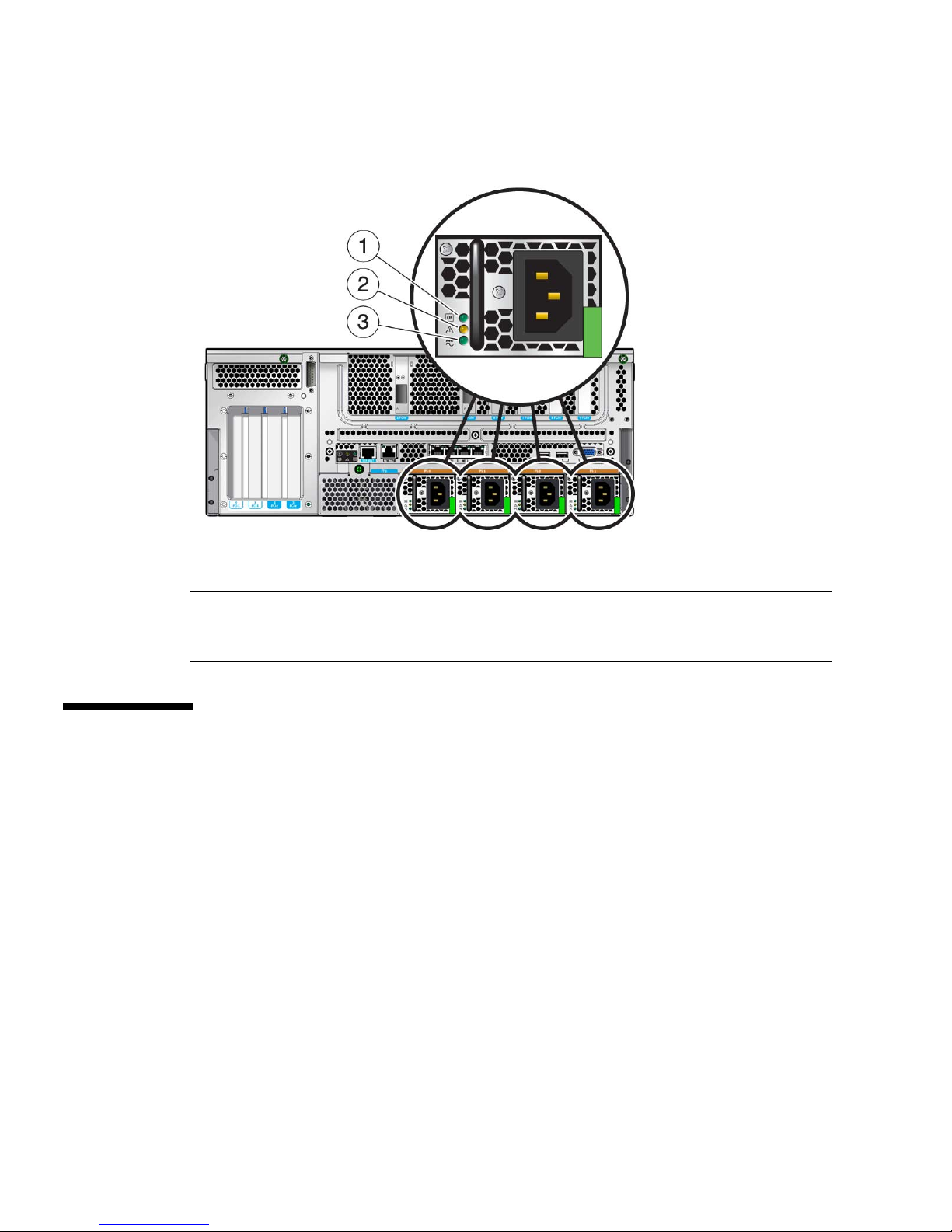
FIGURE 1-4 Rear Panel Power Supply LEDs on the Sun Netra T5440 Server
Figure Leg end
1 Power Supply Output On LED (Green)
2 Power Supply Service Required LED (Amber)
3 Power Supply Input Power OK LED (Green)
Additional Feature Information
Chip-Multithreaded Processor and Memory
Technology
The UltraSPARC T2 Plus multicore processor is the basis of the Sun Netra T5440
server. The UltraSPARC T2 processor is based on chip multithreading (CMT)
technology that is optimized for highly threaded transactional processing. The
UltraSPARC T2 processor improves throughput while using less power and
dissipating less heat than conventional processor designs.
Depending on the model purchased, each processor chip has four, six, or eight
UltraSPARC cores. Each core has two integer pipelines. Each pipeline runs four
threads, for a total of eight threads per core.
14 Sun Netra T5440 Server Installation Guide • May 2011

Additional processor components, such as L1 cache, L2 cache, memory access
crossbar, memory controllers, and the I/O interface have been carefully tuned for
optimal performance.
Performance Enhancements
The Sun Netra T5440 server expands the CoolThreads family to include dual socket
systems. The server delivers extremely high compute density with up to 128 threads
in 4 rack units.
The server provides advanced power management through the UltraSPARC T2
power management features that work at both the core and the memory levels of the
processor. These features include the ability to reduce instruction issue rates, parking
of idle threads and cores, and the ability to turn off clocks in both cores and memory
to reduce power consumption.
In addition, the server offers the following features:
■ High memory density with up to 256 (with full 32 slots) Gbytes in 4 rack units.
■ High internal storage capacity with 1742 Gbytes available
■ Robust I/O bandwidth with 8 lanes available in all of the PCIe slots.
■ Eco-responsibility through the use of power supplies that are compliant with 80
Plus and Climate Savers computing initiatives.
Preinstalled Solaris Operating System
The Sun Netra T5440 server is preinstalled with the Solaris 10 OS, and offers the
following Solaris OS features:
■ Stability, high performance, scalability, and precision of a mature 64-bit operating
system
■ Support for over 5,000 leading technical and business applications, and thousands
of Java based services
■ Solaris Containers – Isolate software applications and services using flexible,
software-defined boundaries
■ DTrace – A comprehensive dynamic tracing framework for tuning applications
and troubleshooting systemic problems in real time
■ Predictive Self-Healing – Capability that automatically diagnoses, isolates, and
recovers from many hardware and application faults
■ Security – Advanced security features designed to protect the enterprise at
multiple levels
Chapter 1 Sun Netra T5440 Features Overview 15

■ Network Performance – Completely rewritten TCP/IP stack dramatically
improves the performance and scalability of your networked services
You can use the preinstalled Solaris 10 OS, or reinstall a supported version of the
Solaris 10 OS from your network, CD, or downloaded copy. In some cases, if you
reinstall the Solaris OS, you must also install patches. Refer to the Sun Netra T5440
Server Product Notes for information on the supported OS releases for your server.
Hardware-Assisted Cryptography
The UltraSPARC T2 Plus multicore, multithreaded, processors provide hardwareassisted acceleration of symmetric, asymmetric, hashing, and random number
generation cryptographic operations as follows:
■ Asymmetric algorithms – RSA, DSA, Diffie Hellman, and Elliptic Curve
cryptography
■ Symmetric algorithms – AES, 3DES, and RC$
■ Hashing algorithms – SHA1, SHA256, and MD5
The Solaris 10 OS provides the multithreaded device driver that supports the
hardware-assisted cryptography.
Support for Virtualization Through
Logical Domains
The Sun Netra T5440 server supports the use of Logical Domains (LDoms)
technology. Through the use of the Solaris OS and the built-in server firmware, and
by installing the Logical Domains Manager software, you can virtualize the compute
services that run on your server. LDoms technology is open source technology, and
is included at no additional cost.
A logical domain is a discrete, logical grouping with its own operating system,
resources, and identity within a single computer system. Each logical domain can be
created, destroyed, reconfigured, and rebooted independently, without requiring a
power cycle of the server.
You can run a variety of applications software in different logical domains and keep
them independent for performance and security purposes.
Each logical domain can be managed as an entirely independent machine with its
own resources, such as:
■ Kernel, patches, and tuning parameters
■ User accounts and administrators
16 Sun Netra T5440 Server Installation Guide • May 2011

■ Network interfaces, MAC addresses, and IP addresses
Each logical domain can interact only with those server resources made available to
it, and the configuration is controlled using the Logical Domains Manager.
For more information on Logical Domains, refer to the Logical Domains (LDoms)
Administration Guide.
Remote Manageability With ILOM
The Integrated Lights Out Manager (ILOM) feature is a service processor, built into
the server, that enables you to remotely manage and administer the server. The
ILOM software is preinstalled as firmware, and initializes as soon as you apply
power to the system.
ILOM enables you to monitor and control your server over an Ethernet connection
(supports SSH), or by using a dedicated serial port for connection to a terminal or
terminal server. ILOM provides a command-line interface and a browser-based
interface to remotely administer geographically distributed or physically
inaccessible machines. In addition, ILOM enables you to run diagnostics (such as
POST) remotely that would otherwise require physical proximity to the server ’s
serial port.
You can configure ILOM to send email alerts of hardware failures and warnings, and
other events related to the server. The ILOM circuitry runs independently of the
server, using the server ’s standby power. Therefore, ILOM firmware and software
continue to function when the server operating system goes offline or when the
server is powered off. ILOM monitors the following Sun Netra T5440 server
conditions:
■ CPU temperature conditions
■ Hard drive status
■ Enclosure thermal conditions
■ Fan speed and status
■ Power supply status
■ Voltage conditions
■ Faults detected by POST (power-on self-test)
■ Solaris Predictive Self-Healing (PSH) diagnostic facilities
In addition to the ILOM CLI and browser interface (BI), you can set up the server to
use an ALOM CMT compatibility CLI. The ALOM CMT compatibility CLI provides
commands that approximate the ALOM CMT CLI that is a system controller
interfaced provided on some previous servers.
Chapter 1 Sun Netra T5440 Features Overview 17

For information about configuring and using the ILOM service processor, refer to the
latest Integrated Lights Out Management (ILOM) User’s Guide and the Sun Integrated
Lights Out Manager 2.0 (ILOM 2.0) Supplement for the Sun Netra T5440 Server.
High Levels of System Reliability, Availability,
and Serviceability
Reliability, availability, and serviceability (RAS) are aspects of a system’s design that
affect its ability to operate continuously and to minimize the time necessary to
service the system. Reliability refers to a system’s ability to operate continuously
without failures and to maintain data integrity. System availability refers to the
ability of a system to recover to an operational state after a failure, with minimal
impact. Serviceability relates to the time it takes to restore a system to service
following a system failure. Together, reliability, availability, and serviceability
features provide for near continuous system operation.
To deliver high levels of reliability, availability, and serviceability, the Sun Netra
T5440 server offers the following features:
■ Ability to disable individual threads and cores without rebooting
■ Lower heat generation reduces hardware failures
■ Hot-pluggable hard drives
■ Redundant, hot-swappable power supplies (four)
■ Redundant fan units (not hot-pluggable)
■ Environmental monitoring
■ Internal hardware drive mirroring (RAID 1)
■ Error detection and correction for improved data integrity
■ Easy access for most component replacements
Hot-Pluggable and Hot-Swappable Components
Sun Netra T5440 server hardware is designed to support hot-plugging of the chassismounted hard drives and power supplies. By using the proper software commands,
you can install or remove these components while the system is running. Hot-swap
and hot-plug technology significantly increases the system’s serviceability and
availability by providing the ability to replace hard drives, fan units, and power
supplies without service disruption.
18 Sun Netra T5440 Server Installation Guide • May 2011

Environmental Monitoring
The Sun Netra T5440 server features an environmental monitoring subsystem that
protects the server and its components against:
■ Extreme temperatures
■ Lack of adequate airflow through the system
■ Power supply failures
■ Hardware faults
Temperature sensors are located throughout the system to monitor the ambient
temperature of the system and internal components. The software and hardware
ensure that the temperatures within the enclosure do not exceed predetermined safe
operating ranges. If the temperature observed by a sensor falls below a lowtemperature threshold or rises above a high-temperature threshold, the monitoring
subsystem software lights the amber Service Required LEDs on the front and back
panel. If the temperature condition persists and reaches a critical threshold, the
system initiates a graceful system shutdown. In the event of a failure of the system
controller, backup sensors protect the system from serious damage, by initiating a
forced hardware shutdown. Required LEDs remain lit after an automatic system
shutdown to aid in problem diagnosis.
The power subsystem is monitored in a similar fashion by monitoring power
supplies and reporting any fault in the front and rear panel LEDs.
Support for RAID Storage Configurations
You can set up hardware RAID 1 (mirroring) and hardware RAID 0 (striping)
configurations for any pair of internal hard drives, providing a high-performance
solution for hard drive mirroring.
By attaching one or more external storage devices to the Sun Netra T5440 server, you
can use a redundant array of independent drives (RAID) software application such
as Solstice DiskSuite™ or VERITAS Volume Manager to configure system drive
storage in a variety of different RAID levels. Software RAID applications such as
VERITAS Volume Manager are not included with this server. You must obtain and
license them separately.
Error Correction and Parity Checking
The UltraSPARC T2 Plus multicore processor provides parity protection on its
internal cache memories, including tag parity and data parity on the D-cache and Icache. The internal L2 cache has parity protection on the tags, and ECC protection
on the data.
Chapter 1 Sun Netra T5440 Features Overview 19

Advanced ECC corrects up to 4 bits in error on nibble boundaries, as long as the bits
are all in the same DRAM. If a DRAM fails, the DIMM continues to function.
Fault Management and Predictive Self Healing
The Sun Netra T5440 server provides the latest fault management technologies. The
Solaris 10 OS architecture provides a means for building and deploying systems and
services capable of Predictive Self-healing. Self-healing technology enables systems to
accurately predict component failures and mitigate many serious problems before
they actually occur. This technology is incorporated into both the hardware and
software of the Sun Netra T5440 server.
At the heart of the predictive self-healing capabilities is the Solaris Fault Manager, a
new service that receives data relating to hardware and software errors, and
automatically and silently diagnoses the underlying problem. Once a problem is
diagnosed, a set of agents automatically responds by logging the event, and if
necessary, takes the faulty component offline. By automatically diagnosing
problems, business-critical applications and essential system services can continue
uninterrupted in the event of software failures, or major hardware component
failures.
Rackmountable Enclosure
The Sun Netra T5440 server uses a space-saving, 4U-high, rackmountable enclosure
that can be installed into a variety of industry standard racks.
20 Sun Netra T5440 Server Installation Guide • May 2011

CHAPTER
2
Preparing for Installation
This chapter provides background information about the server installation
procedures.
This chapter contains these topics:
■ “Tools and Equipment Needed” on page 23
■ “Shipping Kit Inventory List” on page 23
■ “Optional Component Installation” on page 24
■ “ESD Precautions” on page 24
■ “Installation Overview” on page 24
■ “Safety Precautions” on page 26
Power Redundancy and Requirements
The Sun Netra T5440 server provides four hot-swappable power supplies in a 2+2
redundant configuration. The system will continue operating under the following
fault conditions:
1. A power source failure which removes input power from one or two power
supplies.
2. Failure of one or two power supplies.
3. Service actions which require removal of one or two power supplies.
The Sun Netra T5440 server may be operated on two, three, or four power supplies
depending on the ambient temperature conditions.
Failure to adhere to the following guidelines could result in a temporary system shut
down due to activation of over temperature protection in the power supplies.
21

■ At room ambient temperatures of 30˚ C or less, the system may be operated
continuously with two or more power supplies functioning.
■ At room ambient temperatures between 30˚ C and 45˚ C, the system may be
operated continuously with three or four power supplies functioning.
■ At room ambient temperatures between 30˚ C and 45˚ C, the system may be
operated for up to five minutes with two power supplies functioning.
■ At room ambient temperatures above 45˚ C, all four power supplies must be
functioning.
Changing Sun Netra Rack Servers from AC to DC
Input or From DC to AC Input
Safety agency requirements prohibit Sun Microsystems from changing a product
from AC input to DC input or from DC input to AC input after the product has been
removed from the agency approved manufacturing site.
Additional Power System Information
■ The total input power for the system is divided equally among the power
supplies in operation.
■ Reversing the positive and negative inputs to the power supplies of a DC input
system will not cause damage. However, the power supplies with reversed input
will not operate.
■ The inputs to a power supply are isolated from the system chassis and the other
power supply inputs.
■ The AC or DC power inputs may be at different voltages within the acceptable
range and may have different offset voltages relative to the system chassis.
22 Sun Netra T5440 Server Installation Guide • May 2011

Tools and Equipment Needed
To install the system, you must have the following tools:
■ No. 2 Phillips screwdriver
■ ESD mat and grounding strap
In addition, you must provide a system console device, such as one of the following:
■ ASCII terminal
■ Workstation
■ Terminal server
■ Patch panel connected to a terminal server
Shipping Kit Inventory List
Standard components of the server are installed at the factory. However, if you
ordered options such as a PCI card and monitor, these are shipped to you separately.
Note – Inspect the shipping cartons for evidence of physical damage. If a shipping
carton appears damaged, request that the carrier’s agent be present when the carton
is opened. Keep all contents and packing material for the agent’s inspection.
Verify that you have received all the parts of your server.
■ Server chassis
■ 19-inch, 4-post hardmount rack kit
■ Package of mounting screws and nuts in assorted sizes to fit various types of
racks and cabinets
■ Wago Type 831-3203 connectors kit for use with DC PSUs
■ M5 nuts for use with chassis grounding studs
■ Any optional components that were ordered with the server
Chapter 2 Preparing for Installation 23

Optional Component Installation
The standard components of the server are installed at the factory. However, if you
ordered options such as additional memory or PCI cards, these will be shipped
separately. If possible, install these components prior to installing the server in a
rack.
Note – There is a 25 Watt maximum load for PCI Slots 0-3, and a 15 Watt maximum
load for PCI (or XAUI) Slots 4-9.
If you ordered any options that are not factory-installed, see the Sun Netra T5440
Server Service Manual for installation instructions.
Note – The list of optional components can be updated without notice. See the
product web pages for the most current list of components supported in the server.
(http://www.sun.com/products-n-solutions/hw/networking/)
ESD Precautions
Electronic equipment is susceptible to damage by static electricity. Use a grounded
antistatic wriststrap, footstrap, or equivalent safety equipment to prevent
electrostatic damage (ESD) when you install or service the servers.
Caution – To protect electronic components from electrostatic damage, which can
permanently disable the system or require repair by service technicians, place
components on an antistatic surface, such as an antistatic discharge mat, an antistatic
bag, or a disposable antistatic mat. Wear an antistatic grounding strap connected to
a metal surface on the chassis when you work on system components.
Installation Overview
This installation guide provides procedures that are to be performed in the following
order.
24 Sun Netra T5440 Server Installation Guide • May 2011

1. Verify that you have received all of the components that ship with your server.
See “Shipping Kit Inventory List” on page 23.
2. Gather configuration information for your system. See your system administrator
for specific details, including these parameters:
■ Netmask
■ IP address for the service processor
■ Gateway IP address
3. Install any optional components shipped with your system. If you have
purchased other optional components such as additional memory, install them
prior to mounting the server in a rack. See “Optional Component Installation” on
page 24.
4. Mount the server into a rack or cabinet. See Chapter 3 for 4-post and 2-post racks.
Note – In the rest of this guide, the term rack means either an open rack or a closed
cabinet.
5. Connect the server to a serial terminal or a terminal emulator (PC or workstation)
to display system messages. See “Powering On the System for the First Time” on
page 77.
Caution – The serial terminal or a terminal emulator should be connected before
you connect the power cables. As soon as power is connected to the system, the
service processor immediately powers on and runs diagnostics. Diagnostic test
failures will be printed on the serial terminal. For more information, refer to the
Integrated Lights Out Manager 2.0 (ILOM 2.0) Supplement for the Sun Netra T5440
Server.
6. Connect the data cables to the server, but do not connect the power cable yet. See
“Connecting the Server Cables” on page 66.
7. Connect the power cable to the server and examine the display for any error
messages. See “Powering On the System for the First Time” on page 77.
Caution – There is a potential for electric shock if the server and related equipment
are not properly grounded.
Note – The service processor runs on the 3.3V standby voltage. As soon as AC/DC
power is connected to the system, the service processor immediately powers on,
runs diagnostics, and initializes the ILOM firmware.
Chapter 2 Preparing for Installation 25
8. After the service processor boots, access the ILOM command-line interface (CLI)
through the serial management port. See “Logging In To the Service Processor”
on page 82.
9. Configure the service processor network addresses. See “Configuring the Service
Processor Network Management Port” on page 84.
Note – The service processor network management port is not operational until you
configure network settings for the service processor (through the service processor
serial management port).
10. Commit the changes to the service processor network parameters. See Step 7 in
“Powering On the System for the First Time” on page 77.
11. Power on the server from a keyboard using the ILOM software. See “Powering
On the System for the First Time” on page 77.
12. Configure the Solaris OS. See “Booting the Solaris Operating System” on page 93.
The Solaris OS is preinstalled on the servers. When you power on, you are
automatically guided through the Solaris OS configuration procedure.
13. Install any required patches to the server.
Refer to the Sun Netra T5440 Server Product Notes for a list of required patches.
14. Load additional software from the Solaris media kit (optional).
The Solaris media kit (sold separately) includes several CDs containing software
to help you operate, configure, and administer your server. Refer to the
documentation provided with the media kit for a complete listing of included
software and detailed installation instructions.
Safety Precautions
Caution – Deploy the antitilt bar on the equipment rack before beginning an
installation.
Caution – The Sun Neta T5440 server weighs approximately 80 lb (36.14 kg). Two
people are required to lift and mount this 2U server into a rack enclosure when
using the procedures in this document.
26 Sun Netra T5440 Server Installation Guide • May 2011

Caution – When completing a two-person procedure, always communicate your
intentions clearly before, during, and after each step to minimize confusion.
Chapter 2 Preparing for Installation 27

28 Sun Netra T5440 Server Installation Guide • May 2011

CHAPTER
3
Installing a Sun Netra T5440 Server
Into a Rack
This chapter provides instructions for installing the Sun Netra T5440 server into a 4post or 2-post rack. Topics include:
■ “Rackmounting Options” on page 30
■ “Hardmounting the Server in a 19-Inch 4-Post Rack” on page 30
■ “Mounting the Server in a Sliding Rail 19-Inch 4-Post Rack” on page 35
■ “Hardmounting the Server in a 600 mm 4-Post Rack” on page 47
■ “Hardmounting the Server in a 23-Inch 2-Post Rack” on page 53
■ “Hardmounting the Server in a 19-Inch 2-Post Rack” on page 56
Note – The 19-inch 4-post hardmount rack kit is included in the standard
configuration of the Sun Netra T5440 server.
Note – References to left and right are from your viewpoint as you face either the
front or rear of the equipment.
Caution – The server is heavy. Two people are required to lift and mount the server
into a rack enclosure when following the procedures in this chapter.
29

Rackmounting Options
The Sun Netra T5440 server ships with a 19-inch, 4-post hardmount rack kit (see
“Hardmounting the Server in a 19-Inch 4-Post Rack” on page 30 for installation
instructions). The following lists the four additional rackmount kit options that can
be ordered from Sun. This chapter provides installation instructions for all of these
rackmount kit options.
■ “Mounting the Server in a Sliding Rail 19-Inch 4-Post Rack” on page 35
■ “Hardmounting the Server in a 600 mm 4-Post Rack” on page 47
■ “Hardmounting the Server in a 23-Inch 2-Post Rack” on page 53
■ “Hardmounting the Server in a 19-Inch 2-Post Rack” on page 56
Hardmounting the Server in a 19-Inch 4Post Rack
The hardmount rack kit for a 19-inch 4-post rack consists of:
■ Two hardmount brackets
■ Two rear mount support brackets
■ Two rear mount flanges
■ Two bags of screws
30 Sun Netra T5440 Server Installation Guide • May 2011
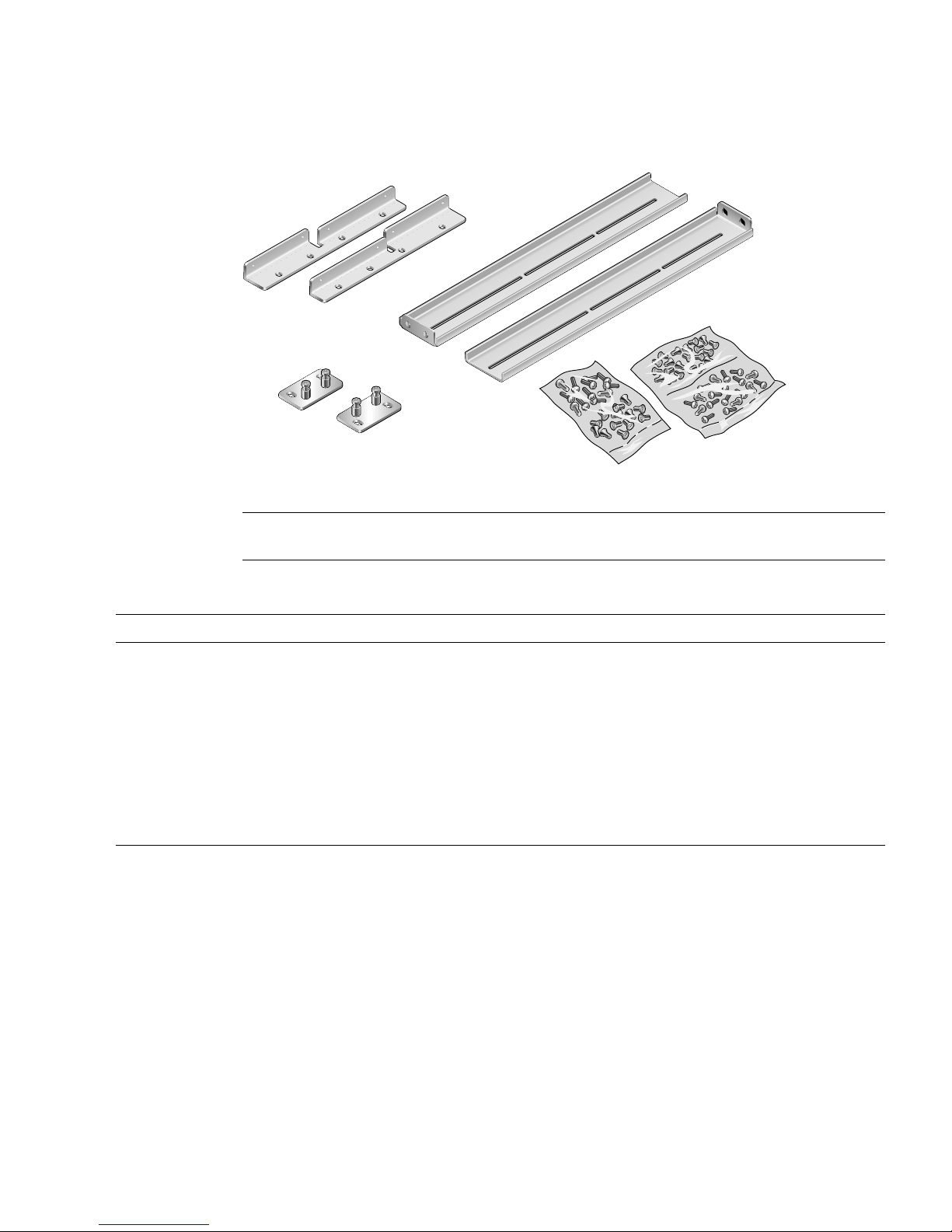
FIGURE 3-1 Contents of the Hardmount 19-Inch 4-Post Kit
Figure Leg end
1 Side brackets 3 Rear plates
2 Screws 4 Rail guides
TABLE 3-1 19-inch 4-Post Rackmount Screw Kit Contents
Number Description Where Used
8 M5 x 8 mm Phillips flathead screws 8 for hardmount brackets
6 M5 x 8 mm Phillips panhead screws 4-6 for rear mount brackets (depending on rack depth)
12 M5 x 12 mm screws 12 for rack, if appropriate
12 M6 x 12 mm screws 12 for rack, if appropriate
12 M6 square clip nuts 12 for rack, if appropriate
12 10-32 x 0.5 in. combo head screws 12 for rack, if appropriate
12 12-24 x 0.5 in. combo head screws 12 for rack, if appropriate
▼ To Hardmount in a 19-Inch 4-Post Rack
1. Get the front hardmount brackets from the rack kit (FIGURE 3-1).
2. Using eight of the supplied M5 x 8 mm flathead Phillips screws (four screws for
each bracket), secure the front hardmount brackets to the sides of the server
(
FIGURE 3-2).
Chapter 3 Installing a Sun Netra T5440 Server Into a Rack 31

FIGURE 3-2 Securing the Hardmount Brackets to the Server
3. Measure the depth of the rack.
4. Get the two rear mount support brackets from the rack kit.
5. Install the rear mount support brackets at the rear of the server, extending the
rear mount support brackets to the measured depth of the rack.
Use two to three of the supplied M5 x 8 mm panhead Phillips screws for each
bracket, depending on the rack depth. If your rack is especially deep, you might
only be able to secure the rear mount support brackets using two screws per side.
32 Sun Netra T5440 Server Installation Guide • May 2011

FIGURE 3-3 Attaching the Rear Mount Support Brackets
6. Lift the server to the desired location in the rack.
Tip – It is strongly suggested to use a mechanical lift for your safety and safe-
handling of the server.
7. Using three screws per side, secure the front hardmount brackets attached to
the sides of the server to the front of the rack.
The size of the screws varies, depending on your particular rack.
Chapter 3 Installing a Sun Netra T5440 Server Into a Rack 33
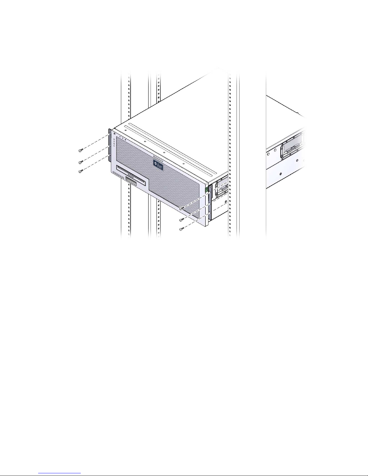
FIGURE 3-4 Securing the Front of the Server to the Rack
8. Get the two rear mount flanges from the rack kit.
9. At the rear of the rack, use the two captive screws to secure the two rear mount
flanges to the rear mount support brackets that are attached to the server.
34 Sun Netra T5440 Server Installation Guide • May 2011
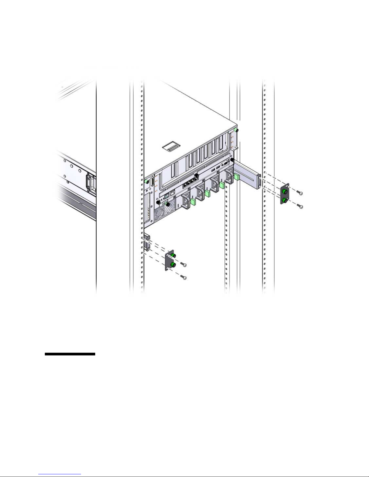
FIGURE 3-5 Securing the Rear of the Server to the Rack
10. Using two screws for each rear mount support bracket, secure the rear mount
support brackets to the rear of the rack.
The size of the screws vary, depending on your particular rack.
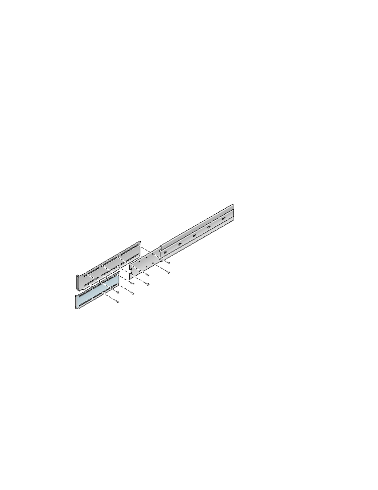
Mounting the Server in a Sliding Rail 19Inch 4-Post Rack
The sliding rail mount kit for a 19-inch 4-post rack consists of:
■ Two 19-inch 4-post Telco slide assemblies
Chapter 3 Installing a Sun Netra T5440 Server Into a Rack 35

■ Two short brackets
■ Two long brackets
■ Two long bracket extenders
■ Two hardmount front brackets
■ Bag of screws
FIGURE 3-6 Contents of the Sliding Rail 19-Inch 4-Post Kit
TABLE 3-2 Sliding Rail 19-inch 4-Post Rackmount Screw Kit Contents
Number Description Where Used
4 M5 x 8 mm Phillips flathead screws 4 for hardmount front brackets
8 Shoulder screws 8 for glides
10 M6 brass collar screws 4 for short brackets, 4 for long brackets, 2 extra
8 M5 panhead screws 8 for slides
12 M5 x 12 mm screws 20 for rack, if appropriate
12 M6 x 12 mm screws 12 for rack, if appropriate
36 Sun Netra T5440 Server Installation Guide • May 2011

TABLE 3-2 Sliding Rail 19-inch 4-Post Rackmount Screw Kit Contents (Continued)
Number Description Where Used
12 M6 square clip nuts 12 for rack, if appropriate
12 10-32 x 0.5 in. combo head screws 12 for rack, if appropriate
12 12-24 x 0.5 in. combo head screws 12 for rack, if appropriate
Note – The front-to-back rail spacing must be at least 755.7 mm (29.75 inches) and
not more than 755.7 mm (29.75 inches) from the outside face of the front rail to the
outside face of the back rail. If the spacing exceeds the maximum measurement,
install the rail extenders as described in “To Install the Long Bracket Extenders” on
page 45 .
▼ Mounting the Server in a 19-Inch 4-Post Rack
With Sliding Rails
1. Get the hardmount brackets and M5 x 8 mm flathead Phillips screws from the
rack kit (
FIGURE 3-6).
2. Using four of the supplied M5 x 8 mm flathead Phillips screws (two screws for
each bracket), secure the hardmount brackets to the sides of the server
(
FIGURE 3-7).
Chapter 3 Installing a Sun Netra T5440 Server Into a Rack 37

FIGURE 3-7 Securing the Hardmount Bracket to the Server
3. Get the Telco slide assemblies from the rack kit (FIGURE 3-6).
4. Press in the button on each slide and pull the glide completely out of the slide
(
FIGURE 3-8).
38 Sun Netra T5440 Server Installation Guide • May 2011

FIGURE 3-8 Dismantling the Slide
5. Align the holes in the glides with the appropriate holes on the sides of the
server and, using the eight screws from the ship kit (four screws for each side),
secure the glides to the sides of the server (
FIGURE 3-9).
Chapter 3 Installing a Sun Netra T5440 Server Into a Rack 39
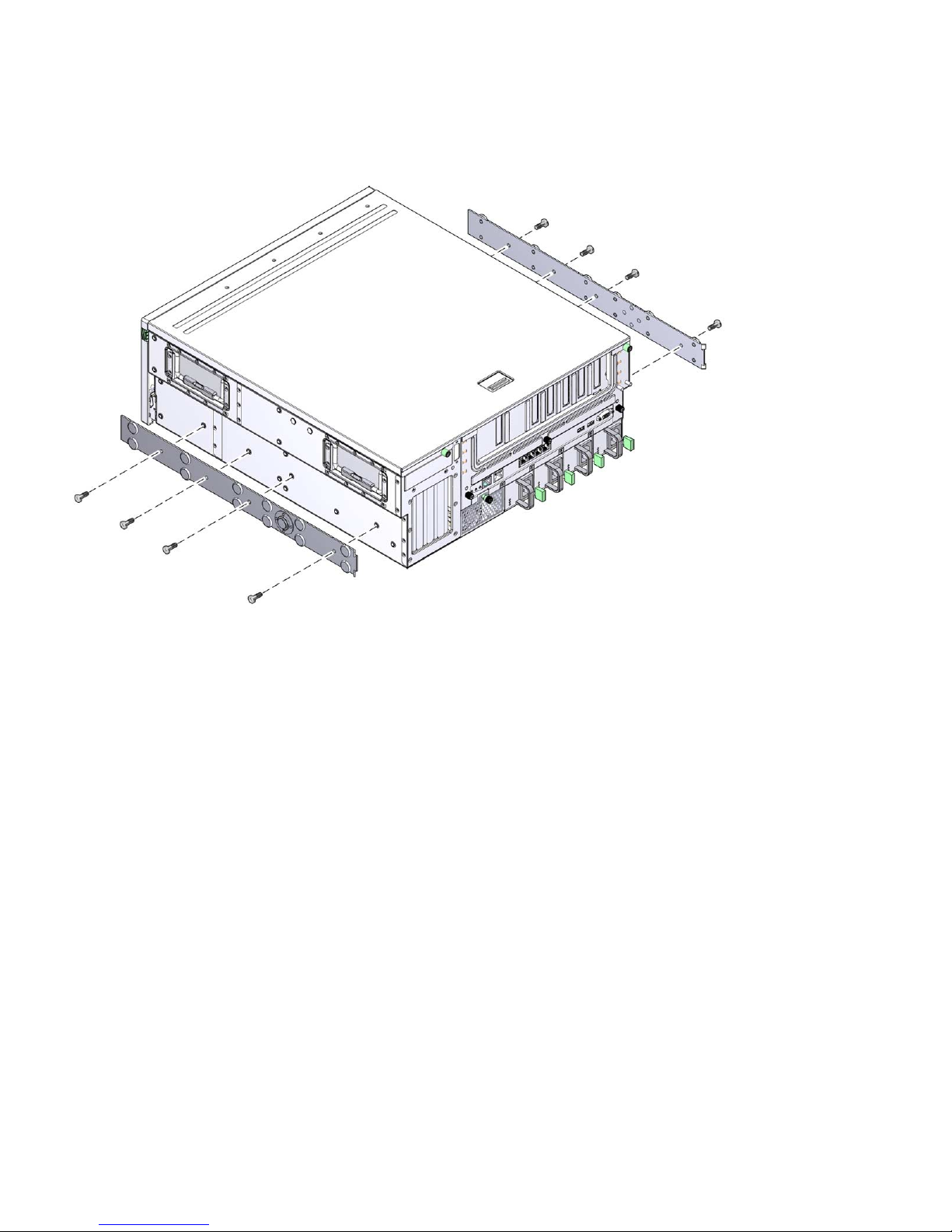
FIGURE 3-9 Securing the Guides to the System Chassis
6. Get the short brackets and long brackets from the rackmount kit (FIGURE 3-6).
7. Lift each short bracket to the desired position at the front of the rack and attach
a short bracket to each of the front rack uprights (
FIGURE 3-10).
Use two of the brass M6 collar screws and M6 cage nuts (if required) to secure
each bracket.
40 Sun Netra T5440 Server Installation Guide • May 2011

FIGURE 3-10 Securing the Short Brackets to the Front of the Rack
8. Lift each long bracket to the desired position at the rear of the rack and attach a
long bracket to each of the rear rack uprights (
FIGURE 3-11).
To secure each bracket, use two of the brass M6 collar screws and M6 cage nuts (if
required), exactly as you did for the front rack uprights in the previous step.
Note – If the dimension is greater than 755.7 mm, attach the rail extenders to the
long brackets as described in “To Install the Long Bracket Extenders” on page 45.
Chapter 3 Installing a Sun Netra T5440 Server Into a Rack 41

FIGURE 3-11 Securing the Long Brackets to the Rear of the Rack
9. Extend a slide to line up the access holes with the front screw holes.
10. Using the M5 panhead screws (four for the short bracket and four for the long
bracket), secure the slide onto the short and long brackets at the front and rear
of the rack (
FIGURE 3-12).
42 Sun Netra T5440 Server Installation Guide • May 2011

FIGURE 3-12 Securing the Slide to the Brackets
11. Repeat Step 9 and Step 10 for the slide on the other side of the rack.
12. Push the slides completely into the assembly on each side of the rack and
release the stop catches.
13. Align the glides attached to the system with the slide assemblies in the rack.
14. You might find that there is too much or too little room between the two slides
mounted in the rack. The glides attached to the system also might not align
correctly with the slides in the rack. If either situation occurs, loosen the M6
collar screws and cage nuts on the long and short brackets (Step 7 and Step 8),
move them inward or outward to the appropriate points, then tighten the
servers again.
15. Push in the slide buttons and slide the system all the way into the rack
enclosure (
FIGURE 3-13).
Chapter 3 Installing a Sun Netra T5440 Server Into a Rack 43

FIGURE 3-13 Sliding the System Into the Rack
16. Using one screw per side, secure the front of the hardmount brackets that are
attached to the sides of the server to the front of the rack (
The size of the screws varies, depending on your particular rack.
44 Sun Netra T5440 Server Installation Guide • May 2011
FIGURE 3-14).
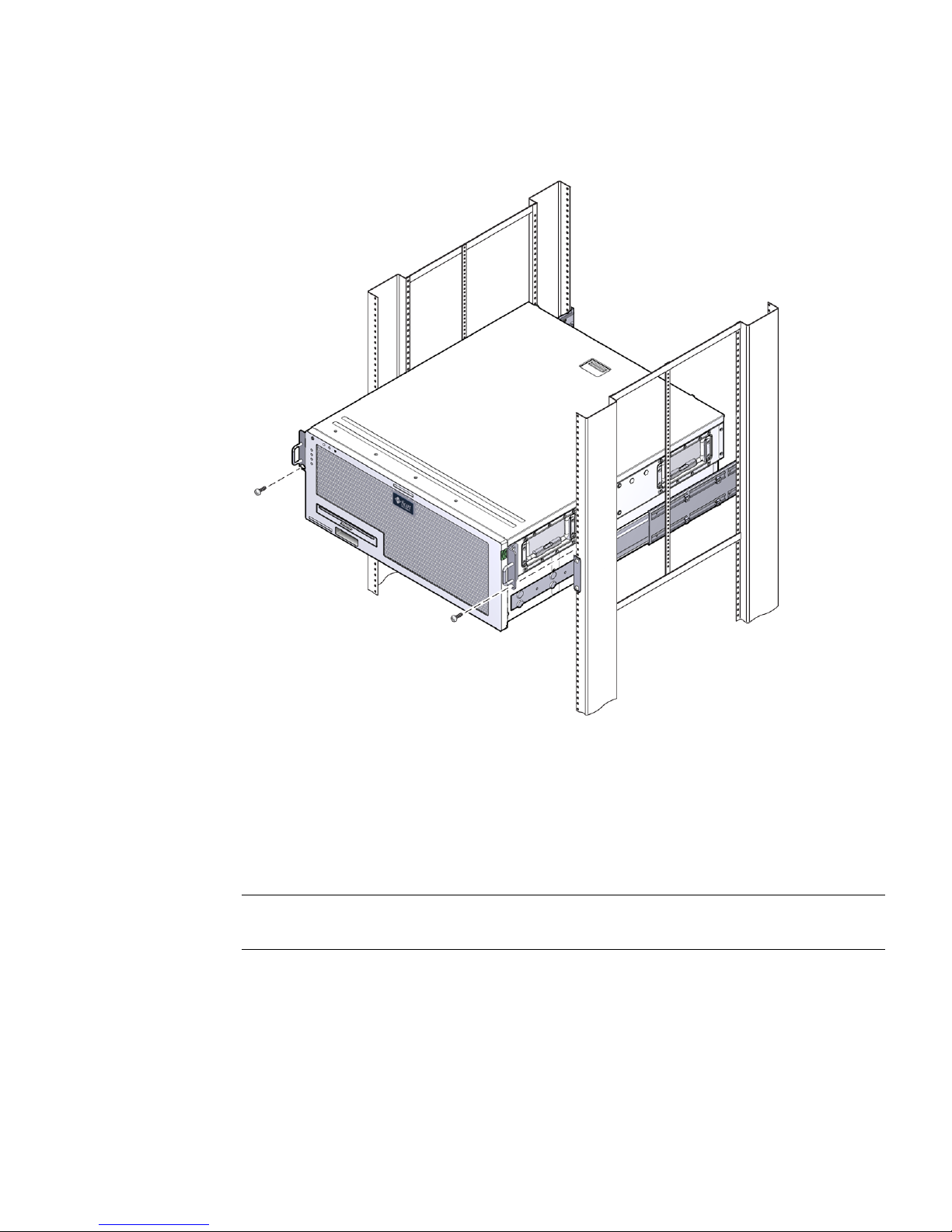
FIGURE 3-14 Securing the Front of the Server to the Rack
▼ To Install the Long Bracket Extenders
Use this procedure to attach the long bracket extenders to the long brackets and slide
assemblies. See for mounting details when using this procedure.
Note – If the long brackets are already attached to the slide assembly, you might
have to remove the long brackets and reinstall them using this procedure.
1. Locate the long bracket extenders.
The extenders are shorter than the long brackets and do not have clip nuts
attached.
2. Place an extender and slide assembly inside a long bracket.
Chapter 3 Installing a Sun Netra T5440 Server Into a Rack 45
3. Install two M5 panhead screws through the rear set of holes in the slide
assembly and into the front clip nuts in the center slots of the long bracket.
Tighten the screws.
4. Install two M5 panhead screws through one of the front set of holes in the slide
assembly and into the matching clip nuts in the long bracket.
Tighten the screws.
5. Install two M5 panhead screw through the front slots of the bracket extender
and into the rear clip nuts in the center slots of the long bracket.
Hand tighten the screws.
6. Install the two M5 panhead screws through the center slot of the bracket
extender and into the matching clip nuts on the long bracket.
Hand tighten the screws.
FIGURE 3-15 Installing Extender and Slide Assembly on Long Bracket
7. Secure the extender brackets and slide assemblies in the rack as shown in
(
FIGURE 3-16).
Adjust the rails to the proper length, tighten the screws on the extenders, and
install four M6 collar screws (two in front bracket and two in the rear bracket) for
each sliding rail assembly.
46 Sun Netra T5440 Server Installation Guide • May 2011

FIGURE 3-16 Securing the Long Bracket Extenders and Slide Assembly to Rack
Hardmounting the Server in a 600 mm 4Post Rack
The hardmount kit for a 600 mm 4-post rack consists of:
■ Two rear mount flanges
■ Two front adjuster brackets
■ One bag of screws
You will also need the two hardmount brackets and two rear mount support
brackets from the standard rackmount kit that came with the Sun Netra T5440 server
server (
FIGURE 3-17).
Chapter 3 Installing a Sun Netra T5440 Server Into a Rack 47

FIGURE 3-17 Contents of the Hardmount 600 mm 4-Post Kit
TABLE 3-3 Hardmount 600 mm 4-Post Rackmount Screw Kit Contents
Number Description Where Used
8 M5 x 8 mm Phillips flathead screws 8 for hardmount brackets
14 M5 x 8 mm Phillips panhead screws 8 for front adjuster brackets and 4-6 for rear mount
brackets (depending on rack depth)
12 M5 x 12 mm screws 12 for rack, if appropriate
12 M6 x 12 mm screws 12 for rack, if appropriate
12 M6 square clip nuts 12 for rack, if appropriate
12 10-32 x 0.5 in. combo head screws 12 for rack, if appropriate
12 12-24 x 0.5 in. combo head screws 12 for rack, if appropriate
▼ To Hardmount the Server in a 600 mm 4-Post
Rack
1. Get the two front hardmount brackets from the standard rack kit (FIGURE 3-17).
These front hardmount brackets came as part of the standard Sun Netra T5440
server server ship kit, not as part of the 600 mm four-post rackmount ship kit.
2. Using eight of the supplied M5 x 8 mm flathead Phillips screws (four screws for
each bracket), secure the front hardmount brackets to the sides of the server
(
FIGURE 3-18).
48 Sun Netra T5440 Server Installation Guide • May 2011

FIGURE 3-18 Securing the Hardmount Brackets to the Server
3. Measure the depth of the rack.
4. Get the two rear mount support brackets from the standard rack kit
(
FIGURE 3-17).
These rear mount support brackets came as part of the standard Sun Netra T5440
server server ship kit, not as part of the 600 mm four-post rackmount ship kit.
5. Install the rear mount support brackets at the rear of the server, extending the
rear mount support brackets to the measured depth of the rack (
FIGURE 3-19).
Use two to three of the supplied M4 x 8 mm panhead Phillips screws for each
bracket, depending on the rack depth. If your rack is especially deep, you may
only be able to secure the rear mount support brackets using only two screws per
side.
Chapter 3 Installing a Sun Netra T5440 Server Into a Rack 49
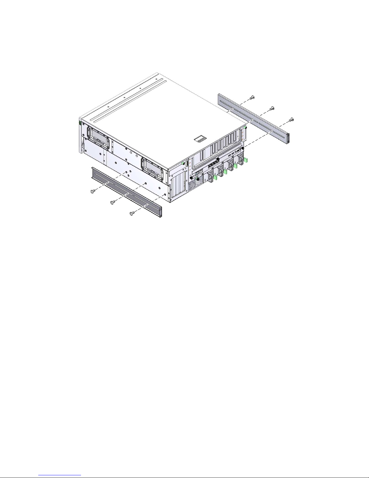
FIGURE 3-19 Attaching the Rear Mount Support Brackets
6. Get the 600 mm front adjuster brackets from the rack kit.
7. Using eight of the supplied M5x8mmpanhead Phillips screws (four screws
for each adjuster bracket), attach the front adjuster brackets to the front
hardmount brackets.
50 Sun Netra T5440 Server Installation Guide • May 2011
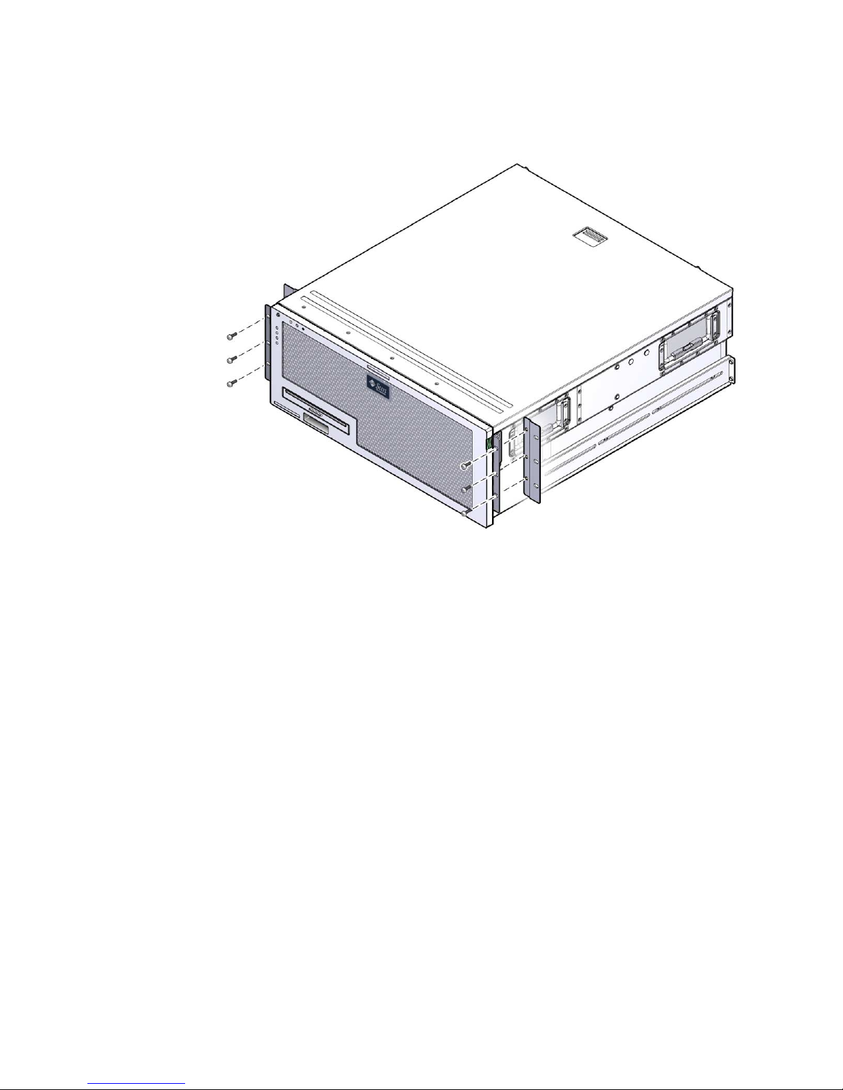
FIGURE 3-20 Attaching the Front Adjuster Brackets to the Front Hardmount Brackets
8. Lift the server to the desired location in the rack.
9. Using three screws per side, secure the front adjuster brackets to the front of
the rack.
The size of the screws varies, depending on your particular rack.
Chapter 3 Installing a Sun Netra T5440 Server Into a Rack 51

FIGURE 3-21 Attaching the Front Adjuster Brackets to the Rack
10. Get the two rear mount flanges from the rack kit.
11. At the rear of the rack, use the captive screws to secure the two rear mount
flanges to the rear mount support brackets that are attached to the server.
52 Sun Netra T5440 Server Installation Guide • May 2011
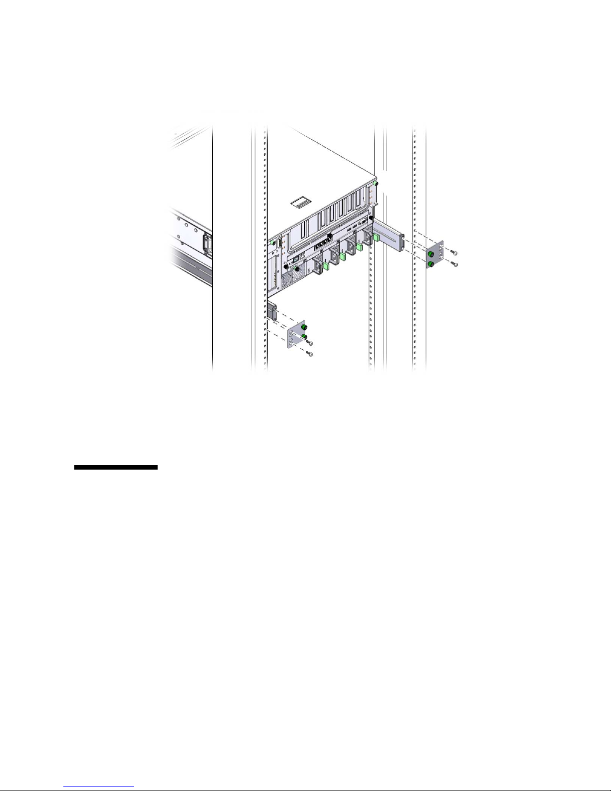
FIGURE 3-22 Securing the Rear Mount Flange
12. Using two screws for each rear mount support bracket, secure the rear mount
support brackets to the rear of the rack.
The size of the screws vary, depending on your particular rack.
Hardmounting the Server in a 23-Inch 2Post Rack
The hardmount kit for a 23-inch 2-post rack consists of:
■ Two side brackets
■ Bag of screws
Chapter 3 Installing a Sun Netra T5440 Server Into a Rack 53

FIGURE 3-23 Contents of the Hardmount 23-Inch 2-Post Kit
TABLE 3-4 Hardmount 23-Inch 2-Post Rackmount Screw Kit Contents
Number Description Where Used
8 M5 x 8 mm Phillips panhead screws 8 for side brackets
12 M5 x 12 mm screws 12 for rack, if appropriate
12 M6 x 12 mm screws 12 for rack, if appropriate
12 M6 square clip nuts 12 for rack, if appropriate
12 10-32 x 0.5 in. combo head screws 12 for rack, if appropriate
12 12-24 x 0.5 in. combo head screws 12 for rack, if appropriate
▼ To Hardmount the Server in a 23-Inch 2-Post
Rack
1. Get the side brackets from the rack kit (FIGURE 3-23).
2. Using eight of the M5x8mmpanhead Phillips screws (four for each side
bracket), secure the side brackets to the sides of the server (
Note – Using eight of the M5 x 8 mm panhead Phillips screws (four for each side
bracket), secure the side brackets to the sides of the server.
FIGURE 3-24).
54 Sun Netra T5440 Server Installation Guide • May 2011

FIGURE 3-24 Securing the Slide Brackets to the Side of the Server
3. Lift the server to the desired location in the rack.
4. Using three screws per side, secure the front hardmount brackets attached to
the sides of the server to the front of the rack.
The size of the screws varies, depending on your particular rack.
Chapter 3 Installing a Sun Netra T5440 Server Into a Rack 55

FIGURE 3-25 Securing the Front of the Server to the Rack
Hardmounting the Server in a 19-Inch 2Post Rack
The hardmount kit for a 19-inch 2-post rack consists of:
■ Two hardmount brackets
56 Sun Netra T5440 Server Installation Guide • May 2011

■ Two bags of screws
■ Two rear mount support brackets (not used in this option)
■ Two rear mount flanges (not used in this option)
FIGURE 3-26 Contents of the Hardmount 19-Inch 2-Post Kit
TABLE 3-5 19-inch 2-Post Rackmount Screw Kit Contents
Number Description Where Used
8 M5 x 8 mm Phillips flathead screws 8 for hardmount brackets
6 M5 x 8 mm Phillips panhead screws 6 for rear mount brackets (not used in this option)
12 M5 x 12 mm screws 12 for rack, if appropriate
12 M6 x 12 mm screws 12 for rack, if appropriate
12 M6 square clip nuts 12 for rack, if appropriate
12 10-32 x 0.5 in. combo head screws 12 for rack, if appropriate
12 12-24 x 0.5 in. combo head screws 12 for rack, if appropriate
▼ To Hardmount the Server in a 19-Inch 2-Post
Rack
1. Get the side brackets from the rack kit (FIGURE 3-26).
2. Using eight of the M5 x 8 mm panhead Phillips screws (four for each side
bracket), secure the side brackets to the sides of the server (
FIGURE 3-27).
Chapter 3 Installing a Sun Netra T5440 Server Into a Rack 57

Note – The wide, flat side of the brackets are facing the rear of the server for this
rackmount option, not the front.
FIGURE 3-27 Securing the Side Brackets to the Side of the Server
3. Lift the server into the rack.
4. Using three screws for each bracket, secure the front of the server to the front of
the rack.
58 Sun Netra T5440 Server Installation Guide • May 2011

FIGURE 3-28 Installing and Securing the Server in the 2-Post Rack
Chapter 3 Installing a Sun Netra T5440 Server Into a Rack 59

60 Sun Netra T5440 Server Installation Guide • May 2011

CHAPTER
4
Cabling the Server
This chapter provides instructions for cabling the server. Topics include:
■ “Cable Connections and Ports” on page 62
■ “Connecting the Server Cables” on page 66
■ “DC Operation Conditions and Procedures” on page 70
Note – Both AC and DC versions of the server must be installed in a restricted-
access location.
Caution – The Sun Netra T5440 must not be directly connected to Outside Plant
cables.
WARNING: The intra-building port(s) of the equipment or subassembly is suitable
for connection to intrabuilding or unexposed wiring or cabling only. The intrabuilding port(s) of the equipment or subassembly MUST NOT be metallically
connected to interfaces that connect to the OSP or its wiring. These interfaces are
designed for use as intra-building interfaces only (Type 2 or Type 4 ports as
described in GR-1089-CORE, Issue 4) and require isolation from the exposed OSP
cabling. The addition of Primary Protectors is not sufficient protection in order to
connect these interfaces metallically to OSP wiring.
Note – You must use an external Surge Protective Device (SPD) for the AC power
input source of the server.
61

Cable Connections and Ports
The following list describes the server’s cable connections and ports:
■ Minimum cable connections for the server:
■ At least one system on-board Ethernet network connection (NET port)
■ The service processor serial management port (SER MGT port)
■ The service processor network management port (NET MGT port)
■ AC or DC power cables for the two system power supplies
■ Service processor management ports: There are two serial management ports for
use with the ILOM system controller.
■ The service processor serial management port (labeled SER MGT) uses an RJ-
45 cable and is always available. This is the default connection to the ILOM
system controller.
■ The service processor network management port (labeled NET MGT) is the
optional connection to the ILOM system controller. This port is not available
until you have configured network settings for the system controller (through
the service processor serial management port). See “Enabling the Service
Processor Network Management Port” on page 82. The service processor
network management port uses an RJ-45 cable for a 10/100BASE-T connection.
This port does not support connections to Gigabit networks.
■ Ethernet ports: Labeled NET0, NET1, NET2, and NET3. The Ethernet interfaces
operate at 10 Mbps, 100 Mbps, and 1000 Mbps. The transfer rates for the Ethernet
ports are given in
TABLE 4-1 Ethernet Connection Transfer Rates
Connection Type IEEE Terminology Transfer Rate
Ethernet 10BASE-T 10 Mbit/sec
Fast Ethernet 100BASE-TX 100 Mbits/sec
Gigabit Ethernet 1000BASE-T 1000 Mbit/sec
■ TTYA serial port: The TTYA serial port has a DB-9 connector, which is located at
the lower right corner of the rear panel (
TABLE 4-1.
FIGURE 4-1). A DB-9 to RJ-45 adapter cable
is included in the shipping kit.
■ Use the DB-9 connector with a null modem cable for serial devices. This port
appears as ttya in Solaris OS and OpenBoot™ messages.
■ This port is not connected to the service processor serial management port.
■ Use this serial port only for general purpose serial data transfers.
62 Sun Netra T5440 Server Installation Guide • May 2011

■ Use a null modem cable or an adapter to perform the crossovers given for each
connector.
■ USB Ports: Two Universal Serial Bus (USB) 2.0 ports labeled USB 0 and USB 1 are
provided on the front panel (
provided on the rear panel (
FIGURE 4-2), and two USB 2.0 ports (USB 3 and 4) are
FIGURE 4-1). USB ports support hot-plugging. You can
connect and disconnect USB cables and peripheral devices while the server is
running, without affecting system operations.
■ You can only perform USB hot-plug operations while the OS is running. USB
hot-plug operations are not supported when the OpenBoot PROM ok prompt
is displayed or before the system has completed booting.
■ You can connect up to 126 devices to each of the four USB controllers, for a
total of 504 USB devices per server.
■ Input AC/DC power cables: Do not attach power cables to the power supplies
until you have finished connecting the data cables, and have connected the server
to a serial terminal or a terminal emulator (PC or workstation). The server goes
into Standby mode and the ILOM system controller initializes as soon as the
input power cables are connected to the power source. System messages might be
lost if the server is not connected to a terminal, PC, or workstation at this time.
Connector Locations
FIGURE 4-1 shows the connectors on the rear panel of the Sun Netra T5440 server.
Chapter 4 Cabling the Server 63

FIGURE 4-1 Rear Panel Cable Connectors, Features, and LEDs on the Rear Panel
Figure Leg end
PCI Slots 0-3: left to right: PCI-X Slot 0 (25 W maximum load), PCI-X Slot 1 (25 W maximum load),
1
PCIe Slot 2 (25 W maximum load), PCIe Slot 3 (25 W maximum load)
2 PCI (or XAUI) Slots 4-9: left to right: PCIe or XAUI Slot 4 (15 W maximum load), PCIe or XAUI Slot
5 (15 W maximum load), PCIe Slot 6 (15 W maximum load), PCIe Slot 7 (15 W maximum load),
PCIe Slot 8 (15 W maximum load), PCIe Slot 9 (15 W maximum load)
3 Service Processor Serial Management Port
4 Service Processor Network Management Port
5 Gigabit Ethernet ports left to right: NET0, NET1, NET2, NET3
6 Power supply 0 LEDs top to bottom: Output On LED (Green), Service Required LED (Yellow), Input
Power OK LED (Green)
7 Power supplies (PSs): left to right: PS 0, PS 1, PS 2, PS 3
8 USB ports left to right: USB2, USB3
9 TTYA serial port
64 Sun Netra T5440 Server Installation Guide • May 2011
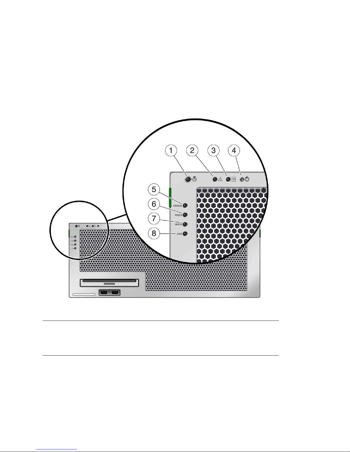
Status Indicator Locations
FIGURE 4-2 shows the status indicators on the front panel of the Sun Netra T5440
server.
FIGURE 4-2 Location of the Bezel Server Status and Alarm Status Indicators
Figure Leg end
1 Locator LED 5 Critical (Red) Alarm Status indicator
2 Fault LED 6 Major (Red) Alarm Status indicator
3 Activity LED 7 Minor (Amber) Alarm Status indicator
4 Power button 8 User (Amber) Alarm Status indicator
Chapter 4 Cabling the Server 65

TABLE 4-2 Bezel Server Status Indicators
Indicator LED Color LED State Component Status
Locator White On Server is identified with the superuser locator
or ILOM setlocator command.
Off Normal state
Fault Amber On The server has detected a problem and requires
the attention of service personnel.
Off The server has no detected faults.
Activity Green On The server is powered up and running the
Solaris Operating System. If the system is
powered on in the OpenBoot ok prompt, the
activity LED is blinking.
Off Either power is not present or the Solaris
software is not running.
Electrical Specifications
TABLE 4-3 provides the electrical specifications of the Sun Netra T5440 server.
TABLE 4-3 Electrical Specifications
Parameter AC DC
Voltage (nominal) 100-127/200-240 VAC -48 VDC or -60 VDC
Input current (maximum) 16 A 32 A
Frequency 50/60 Hz N/A
DC Input Treatment N/A Isolated DC Return (DC-I)
Connecting the Server Cables
To power on the server, you must connect and configure the network and serial
ports. The procedures are given in the following sections.
■ “To Connect the Service Processor Serial Management Port” on page 67
■ “To Connect the Service Processor Network Management Port” on page 68
66 Sun Netra T5440 Server Installation Guide • May 2011

■ “To Connect the Ethernet Network Cables” on page 69
■ “To Connect Power Cables to the Server” on page 70
The server also has serial and USB ports available for connections to optional
devices (see “Cable Connections and Ports” on page 62).
Note – When you are finished connecting the cables to the server, ensure that the
server can slide smoothly in and out of the rack without binding or damaging the
cables..
▼ To Connect the Service Processor Serial
Management Port
The service processor serial management port is marked SER MGT (FIGURE 4-3). It is
the leftmost RJ-45 port on the rear panel.
Note – The cable and DB-9 RJ-45 adapters are for the host serial port, and not for
the server SER MGT port.
Use this port for server management. This port is needed to set up the service
processor network management port, as detailed in “Enabling the Service Processor
Network Management Port” on page 82.
Note – Use the service processor serial management port only for server
management. It is the default connection between the service processor and a
terminal or a computer.
Caution – Do not attach a modem to this port.
● Connect a Category 5 cable from the SER MGT serial management port to the
terminal device.
When connecting either a DB-9 or a DB-25 cable, use an adapter to perform the
crossovers given for each connector.
Chapter 4 Cabling the Server 67

FIGURE 4-3 Service Processor Serial Management Port – Rear Panel
▼ To Connect the Service Processor Network
Management Port
The service processor network management port is labeled NET MGT (FIGURE 4-4). It
is located just to the right of the serial management (SER MGT) port on the rear
panel.
Note – This port is not operational until you configure the network settings
(through the serial managment port), as detailed in “Configuring the Service
Processor Network Management Port” on page 84.
Note – If you have access to a DHCP server on the network, you can see the service
processor get an IP address because the DHCP client is enabled by default.
Note – The service processor network management port is configured by default to
retrieve network settings with Dynamic Host Configuration Protocol (DHCP) and
allow connections using Solaris Secure Shell (SSH). You might need to modify these
settings for your network. Instructions are given in Chapter 5.
● Connect a Category 5 cable from the NET MGT network management port to
your network switch or hub.
68 Sun Netra T5440 Server Installation Guide • May 2011

FIGURE 4-4 Service Processor Network Management Port – Rear Panel
▼ To Connect the Ethernet Network Cables
The server has four network connectors, marked NET0, NET1, NET2, and NET3
(
FIGURE 4-5). These connectors are RJ-45 Gigabit Ethernet.
1. Connect a Category 5 cable from your network switch or hub to Ethernet Port 0
(NET0) on the rear of the chassis.
NET0 is the farthest left port in the 4-port network cluster in
FIGURE 4-5 Service Processor Ethernet Network Ports – Rear Panel
2. Connect Category 5 cables from your network switch or hub to the remaining
Ethernet ports, as needed.
The Ethernet ports are labeled left to right: NET 0, NET1, NET2, NET3.
FIGURE 4-5.
Note – The LEDs located above each NET port are Link/Activity (left) and Speed
(right) indicators for each port.
Chapter 4 Cabling the Server 69

▼ To Connect Power Cables to the Server
Powering on the system for the first time requires special preparation and
procedures. For example, if you have not prepared a display before connecting the
AC power cable, system messages might be lost.
Caution – Finish the hardware procedures in this chapter, but do not attach the AC
power cable yet.
Powering on the system for the first time requires special preparation and
procedures. For example, if you have not prepared a display before connecting the
AC power cable, system messages could be missed.
Caution – The server goes into Standby mode and the service processor initializes
as soon as the AC power cable is connected to the power source.
● Go to “Powering On the System for the First Time” on page 77 for instructions
on connecting the server to AC power.
DC Operation Conditions and
Procedures
This section provides DC power cabling and requirements information.
70 Sun Netra T5440 Server Installation Guide • May 2011

DC Power Source Requirements
TABLE 4-4 lists DC power source requirements for each power supply in the Sun
Netra T5440 server, and
as a whole.
TABLE 4-4 DC Operating Power Limits and Ranges for Each Power Supply in the Server
Description Limit or Range
Input voltage -48 VDC to -60 VDC nominal
Maximum operating input current 16 A
Maximum operating input power 640 W
TABLE 4-5 DC Operating Power Limits and Ranges for the Server
Description Limit or Range
Input voltage -48 VDC to -60 VDC nominal
Maximum operating input current 32 A
TABLE 4-5 lists DC power source requirements for the server
-40 VDC to -75 VDC operating limits
-40 VDC to -75 VDC operating limits
Maximum operating input power 1280 W
DC Supply and Ground Conductor Requirements
The server must meet the following:
■ Suitable conductor material: use copper conductors only
■ Power supply connections through the input connector: 12 AWG (between the
Sun Netra T5440 server and the source). There are three conductors:
■ -48V (negative terminal)
■ Chassis ground connection
■ -48V Return (positive terminal)
■ System ground conductor: 12 AWG (to be connected to the chassis)
■ Cable insulation rating: Minimum of 75˚C (167˚F), low smoke fume (LSF), flame
retardant
■ Cable type one of the following:
■ UL style 1028 or other UL 1581 (VW-1) compliant equivalent
■ IEEE 383 compliant
■ IEEE 1202-1991 compliant
Chapter 4 Cabling the Server 71

■ Branch circuit cable insulation color: Per applicable National Electrical Codes
■ Grounding cable insulation color: Green/Yellow
■ DC power source must meet TNV-2 requirements as defined by UL 60950-1 and
IEC 60950-1
Note – Depending on the DC power source, the -48V (negative terminal) might be
marked with a minus (-) symbol, and the -48V Return (positive terminal) might be
marked with a positive (+) symbol.
When attaching DC cables, keep the following requirement in mind:
Caution – You must restrict the connection of the Sun Netra T5440 server to the DC
power source to minimize the possibility that transient energy will appear on the
main input to the equipment. The DC battery power source must be in the same
premises as the server. The server cannot be in one building with the power source
in another building.
Overcurrent Protection Requirements
■ Overcurrent protection devices must be provided as part of each equipment rack.
■ Circuit breakers must be located between the DC power source and the Sun Netra
T5440 server. Use one 20 A fast trip DC-rated circuit breaker for each power
supply unit.
Note – Overcurrent protection devices must meet applicable national and local
electrical safety codes and be approved for the intended application.
▼ To Assemble the DC Input Power Cable
1. Identify the parts that you will use to assemble the DC input power cable.
The following DC connection parts are required to assemble one or more DC
power input cables. These cables connect the -48V DC input source(s) to the
power supply units.
■ DC input plugs
■ Cage clamp operating lever
■ Tie wraps
2. Turn off power from the DC power source through the circuit breakers.
72 Sun Netra T5440 Server Installation Guide • May 2011

Caution – Do not proceed with these instructions until you have turned off the
power from the DC power source through the circuit breakers.
3. Get a DC input plug from the ship kit.
4. Locate the three wires coming from the DC power source that will be used in
the connection to your unit:
■ -48V (negative terminal)
■ Chassis ground
■ -48V Return (positive terminal)
Note – Depending on the DC power source, the -48V (negative terminal) might be
marked with a minus (-) symbol, and the -48V Return (positive terminal) might be
marked with a positive (+) symbol.
5. Strip 5/16 inches (8 mm) of insulation from each of the wires coming from the
DC power source.
Do not strip more than 5/16 inches (8 mm) from each wire. Doing so leaves
uninsulated wire exposed from the DC connector after the assembly is complete.
6. Open the cage clamp for this section of the DC input plug by taking one of the
following actions:
■ Insert the tip of the cage clamp operating lever into the rectangular hole
directly above the hole in the DC input plug where you want to insert the first
wire. Press down on the cage clamp operating lever (
■ Insert a small slotted screwdriver into the rectangular hole directly above the
FIGURE 4-6).
hole in the DC input plug where you want to insert the first wire, and press
down on the screwdriver (
FIGURE 4-7).
Chapter 4 Cabling the Server 73

FIGURE 4-6 Opening the DC Input Plug Cage Clamp Using the Cage Clamp Operating
Lever
74 Sun Netra T5440 Server Installation Guide • May 2011

FIGURE 4-7 Opening the Cage Clamp Using a Screwdriver
7. Feed the exposed section of the appropriate wire into the rectangular plug hole
in the DC input plug.
FIGURE 4-8 shows which wires should be inserted into each hole in the DC input
plug.
FIGURE 4-8 Assembling the DC Input Power Cable
Figure Leg end
1 Top of connector 3 From chassis ground (green/yellow)
2 From -48V return 4 From -48V
8. Repeat Step 6 and Step 7 for the other two wires to complete the assembly of
the DC input power cable.
Chapter 4 Cabling the Server 75

9. Repeat Step 4 through Step 8 to create as many DC input power cables as you
need for your unit.
You need two DC input power cables for each of the power supplies.
If you need to remove a wire from the DC input plug, insert the cage clamp
operating lever or a small screwdriver into the slot directly above the wire and
press down (
FIGURE 4-6 and FIGURE 4-7). Pull the wire from the DC input plug.
76 Sun Netra T5440 Server Installation Guide • May 2011

CHAPTER
5
Powering On the System
This chapter includes instructions for booting the server and for enabling the system
controller network management port.
The following topics are included:
■ “Powering On the System for the First Time” on page 77
■ “Enabling the Service Processor Network Management Port” on page 82
■ “Logging In To the Service Processor” on page 82
■ “Using the Service Processor for Common Operations” on page 88
■ “Booting the Solaris Operating System” on page 93
■ “Verifying System Functionality” on page 96
Powering On the System for the First
Time
This section provides an overview and instructions for powering on your system the
first time.
ILOM System Console
When you power on the system, the boot process begins under the control of the
Integrated Lights Out Manager (ILOM) system console. The system console displays
status and error messages generated by firmware-based tests during system startup.
77

Note – To see these status and error messages, connect a terminal or terminal
emulator to the serial management port (SERIAL MGT). For a basic procedure to
connect a terminal or terminal emulator, see “To Power On the System for the First
Time” on page 79.
For a more detailed discussion on configuring the system console and connecting
terminals, refer to the Sun Netra T5440 Server Administration Guide.
ILOM Service Processor
After the system console finishes its low-level system diagnostics, the ILOM service
processor initializes and runs a higher level of diagnostics. When you access the
ILOM service processor using a device connected to the serial management port, you
see the output of the ILOM diagnostics.
By default, the network management port is configured to automatically retrieve
network configuration using Dynamic Host Configuration Protocol (DHCP) and to
allow connections using Secure Shell (SSH).
Note – If you are unable to use DHCP and SSH on your network, you must connect
to the ILOM service processor using the serial management port to reconfigure the
network management port. See “Enabling the Service Processor Network
Management Port” on page 82.
Once the network management port (NET MGT) has been assigned an IP address,
you can connect to the ILOM service processor using SSH.
CLIs, User Accounts, and Passwords for
Connecting to the ILOM Service Processor
When connecting to the ILOM service processor for the first time using the serial or
network management ports, the default CLI is ILOM, the default user account is
root, and the default password is changeme. Examples in this document use the
default ILOM CLI.
ILOM also provides an Advanced Lights Out Management (ALOM) compatability
CLI that uses commands that resemble the ALOM CMT CLI commands. To access
the ALOM compatability CLI, you must first create an admin account with the role
of administrator. Once you create the admin account, assign the ALOM
78 Sun Netra T5440 Server Installation Guide • May 2011

compatability CLI as the default CLI (role=administrator, cli=alom). For more
information on using the ALOM compatability CLI, refer to the Integrated Lights Out
Manager 2.0 (ILOM 2.0) Supplement for Sun Netra T5440 Server.
▼ To Power On the System for the First Time
Caution – The serial terminal or a terminal emulator should be connected before
you connect the power cables, or you will not see the system messages. The server
goes into Standby mode and the ILOM service processor initializes as soon as the
AC/DC power cables are connected to the power source.
The service processor runs on the 3.3V standby voltage. As soon as AC/DC power is
connected to the system, the service processor powers on, runs diagnostics, and
initializes the ILOM firmware.
1. Connect a terminal or a terminal emulator (PC or workstation) to the service
processor serial management port.
Configure the terminal or terminal emulator with these settings:
■ 9600 baud
■ 8 bits
■ No parity
■ 1 Stop bit
■ No handshake
Note – When you power on the server for the first time and you do not have a
terminal or terminal emulator (PC or workstation) connected to the service processor
serial management port, you will not see system messages. After connecting to the
server with a terminal or terminal emulator, log in to the ILOM CLI or the ALOM
compatability CLI to get to the service processor console.
2. Turn on the terminal or terminal emulator.
3. Connect the AC/DC power cables to Power Supply 0 and Power Supply 1.
Watch the terminal for system messages.
Chapter 5 Powering On the System 79

FIGURE 5-1 Rear Panel Power Connectors of Oracle’s Sun Netra T5440 Server
Figure Leg end
1 Power Supply Output On LED (Green) 3 Power Supply Input Power OK LED (Green)
2 Power Supply Service Required LED (Amber) 4
After the service processor boots, the service processor login prompt is displayed
on the serial console. The following example shows a partial output from the
service processor boot sequence leading to the login prompt.
80 Sun Netra T5440 Server Installation Guide • May 2011

EXAMPLE 5-1 Sample Service Processor Output
U-Boot 1.1.1 (August 23 2007 - 21:30:12)
...
POST cpu PASSED
POST ethernet PASSED
Hit any key to stop autoboot: 0
## Booting image at fe080000 ...
IP Protocols: ICMP, UDP, TCP, IGMP
Checking all file systems...
fsck 1.37 (21-Mar-2005)
Setting kernel variables ...
... done.
Mounting local filesystems...
Cleaning /tmp /var/run /var/lock.
Identifying DOC Device Type(G3/G4/H3) ...
OK
Configuring network interfaces...Internet Systems Consortium DHCP
Client V3.0.1
Copyright 2007 Internet Systems Consortium.
All rights reserved.
For info, please visit http://www.isc.org/products/DHCP
eth0: config: auto-negotiation on, 100FDX, 100HDX, 10FDX, 10HDX.
Listening on LPF/eth0/00:14:4f:3f:8c:af
Sending on LPF/eth0/00:14:4f:3f:8c:af
Sending on Socket/fallback
DHCPDISCOVER on eth0 to 255.255.255.255 port 67 interval 6
eth0: link up, 100 Mbps Full Duplex, auto-negotiation complete.
DHCPDISCOVER on eth0 to 255.255.255.255 port 67 interval 15
Hostname: hostname.
Starting portmap daemon: portmap.
Initializing random number generator...done.
INIT: Entering runlevel: 3
Starting system log daemon: syslogd and klogd.
Starting periodic command scheduler: cron.
Starting IPMI Stack...... Done.
Starting OpenBSD Secure Shell server: sshd.
Starting Servicetags listener: stlistener.
Starting FRU update program: frutool.
hostname login:
Chapter 5 Powering On the System 81

▼ To Avoid Booting the Solaris Operating System at Start
Up
In hard drive HDD0, the Solaris OS is preinstalled.
● If you do not want to start the preinstalled OS, set the OBP parameter auto-
boot? to false. For example from the ILOM CLI:
-> bootmode bootscript "setenv auto-boot? false"
Enabling the Service Processor Network
Management Port
The service processor network management port is not operational until you
configure network settings for the service processor. Configure the service processor
in this order:
1. After the service processor boots, access the ILOM CLI through the serial
management port. See “To Log In To the Service Processor Using the Serial
Management Port” on page 83.
2. Configure the service processor. See “Configuring the Service Processor Network
Management Port” on page 84.
3. Commit the changes to the service processor parameters. See Step 7 in “To Power
On the System for the First Time” on page 79.
You can now use the network management port at any time to access the service
processor. See “To Log In To the Service Processor Using the Network Management
Port” on page 88.
Logging In To the Service Processor
If you are powering on the system for the first time after installation, use the service
processor serial port to power on the system and run POST. See “To Log In To the
Service Processor Using the Serial Management Port” on page 83.
If the network management port has already been configured, you can use it instead
of the serial management port. See “To Configure the Service Processor Network
Management Port” on page 85.
82 Sun Netra T5440 Server Installation Guide • May 2011

▼ To Log In To the Service Processor Using the
Serial Management Port
After the service processor boots, access the ILOM CLI to configure and manage the
system. The ILOM CLI prompt (->) is displayed at the first time the service
processor is booted. The default configuration provides an ILOM CLI root user
account. The default root password is changeme. Change the password using the
service processor ILOM CLI password command.
1. If this is the first time the system has been powered on, use the password
command to change the root password.
...
Starting OpenBSD Secure Shell server: sshd.
Starting Servicetags listener: stlistener.
Starting FRU update program: frutool.
hostname login: root
Password: changeme
Copyright 2007 Sun Microsystems, Inc. All rights reserved.
Use is subject to license terms.
...
Federal Acquisitions: Commercial Software -- Government Users
Subject to Standard License Terms and Conditions.
...
Warning: password is set to factory default.
-> set /SP/users/root password
Enter new password: ********
Enter new password again: ********
->
Note – After the root password has been set, on subsequent reboots, the ILOM CLI
login prompt is displayed.
2. Enter root for the login name followed by your password.
...
hostname login: root
Password: password (nothing displayed)
Waiting for daemons to initialize...
Chapter 5 Powering On the System 83

Daemons ready
Sun(TM) Integrated Lights Out Manager
Version 2.0.0.0
Copyright 2007 Sun Microsystems, Inc. All rights reserved.
Use is subject to license terms.
->
Configuring the Service Processor Network
Management Port
Note – If your network allows the use of DHCP and SSH, this configuration is
performed automatically the first time you boot the system.
Use this procedure only when:
■ You are unable to use DHCP and SSH on your network.
■ You need to modify the ILOM service processor network management port
settings.
In this procedure, you connect to the ILOM service processor using the serial
management port to manually reconfigure the network management port.
Note – For more information on configuring ILOM, refer to the Integrated Lights Out
Management 2.0 (ILOM 2.0) Supplement for Sun Netra T5440 Server.
Set these network parameters according to the specific details of your network
configuration:
■ /SP/network state – Specifies whether the service processor is on the network
or not
■ /SP/network pendingipaddress – IP address of the service processor
■ /SP/network pendingipgateway – IP address of the gateway for the subnet
■ /SP/network pendingipnetmask – Netmask for the service processor subnet
■ /SP/network pendingipdiscovery - Specifies whether the service processor
uses DHCP or static IP address assignment
■ /SP/network commitpending - Commits the service processor to use the
pending settings
84 Sun Netra T5440 Server Installation Guide • May 2011

Configure these parameters with the set command. The usage is as follows:
set target property=value where /SP/network is the target and
pendingipaddress=xx.x.xx.xxx, for example, is the property=value. The following
example sets the pending service processor IP address:
-> set /SP/network pendingipaddress=xx.x.xx.xxx
Set 'pendingipaddress' to 'xx.x.xx.xxx'
▼ To Configure the Service Processor Network
Management Port
1. Set the /SP/network state parameter to enabled.
-> set /SP/network state=enabled
Set 'state' to 'enabled'
2. Enable and disable SSH connections as needed.
-> set /SP/services/ssh state=enabled
Set 'state' to 'enabled'
-> set /SP/services/ssh state=disabled
Set 'state' to 'disabled'
See the Integrated Lights Out Management 2.0 (ILOM 2.0) Supplement for Sun Netra
T5440 Server for more information about SSH support in ILOM.
3. Choose one of these methods to configure the service processor using
information from your network administrator:
■ Use DHCP to retrieve the network settings. Go to Step 4.
■ Configure a static IP configuration. Go to Step 5.
4. If you choose to use DHCP, set pendingipdiscovery to dhcp.
-> set /SP/network pendingipdiscovery=dhcp
Set 'pendingipdiscovery' to 'dhcp'
Go to Step 6.
5. If you choose to use a static IP configuration, set the parameters
pendingipdiscovery, pendingipaddress, pendingipgateway, and
pendingipnetmask as follows.
Chapter 5 Powering On the System 85

a. Set the service processor
-> set /SP/network pendingipdiscovery=static
Set 'pendingipdiscovery' to 'static'
b. to accept a static IP address.
c. Set the IP address for the service processor.
-> set /SP/network pendingipaddress=service-processor-IPaddr
Set 'pendingipaddress' to 'service-processor-IPaddr'
d. Set the IP address for the service processor gateway.
-> set /SP/network pendingipgateway=gateway-IPaddr
Set 'pendingipgateway' to 'gateway-IPaddr'
e. Set the netmask for the service processor.
-> set /SP/network pendingipnetmask=255.255.255.0
Set 'pendingipnetmask' to '255.255.255.0'
This example uses 255.255.255.0 to set the netmask. Your network
environment subnet might require a different netmask. Use a netmask number
most appropriate to your environment.
6. Use the show /SP/network command to verify that the parameters were set
correctly.
-> show /SP/network
/SP/network
Targets:
Properties:
commitpending = (Cannot show property)
dhcp_server_ip = xx.x.xx.x
ipaddress = xx.x.xx.x
ipdiscovery = dhcp
ipgateway = xx.x.xx.x
ipnetmask = 255.255.252.0
macaddress = 00:14:4F:3F:8C:AF
pendingipaddress = xx.x.xx.x
pendingipdiscovery = static
pendingipgateway = xx.x.xx.x
pendingipnetmask = 255.255.255.0
state = enabled
Commands:
cd
86 Sun Netra T5440 Server Installation Guide • May 2011

set
show
->
Note – After setting the configuration parameters, you must enter the set
/SP/network commitpending=true command for the new values to take affect.
7. Commit the changes to the service processor network parameters.
-> set /SP/network commitpending=true
Set 'commitpending' to 'true'
▼ To Reset the Service Processor
It is not necessary to reset the service processor for new network values to take
effect. To commit the changes to the service processor network parameters, use the
set /SP/network commitpending=true command. See Step 7 in “Configuring
the Service Processor Network Management Port” on page 84.
● Type the reset /SP command.
You are prompted to confirm that you want to reset the service processor. Reply y
when prompted.
-> reset /SP
Are you sure you want to reset /SP (y/n)? y
Note – You can specify the -script option to bypass the confirmation question, for
example, reset -script /SP.
The service processor resets, runs diagnostics, and returns to the login prompt.
...
hostname login: root
Password: password (nothing displayed)
Waiting for daemons to initialize...
Daemons ready
Sun(TM) Integrated Lights Out Manager
Version 2.0.0.0
Copyright 2007 Sun Microsystems, Inc. All rights reserved.
Chapter 5 Powering On the System 87

Use is subject to license terms.
->
▼ To Log In To the Service Processor Using the Network
Management Port
Note – You must configure the service processor parameters shown in “Configuring
the Service Processor Network Management Port” on page 84 before you can use the
network management port.
● Open an SSH session and connect to the service processor by specifying its
network address.
% ssh root@xx.xxx.xx.x
...
Are you sure you want to continue connecting (yes/no)? yes
...
Password: password (nothing displayed)
Waiting for daemons to initialize...
Daemons ready
Sun(TM) Integrated Lights Out Manager
Version 2.0.0.0
Copyright 2007 Sun Microsystems, Inc. All rights reserved.
Use is subject to license terms.
->
Using the Service Processor for Common
Operations
Note – For more information on using the ILOM service processor, refer to the
Integrated Lights Out Manager 2.0 (ILOM 2.0) Supplement for Sun Netra T5440 Server.
88 Sun Netra T5440 Server Installation Guide • May 2011
 Loading...