

Page 1

Sun Fire X4800 Server Rack Mounting and
Shipping Bracket User's Guide
Part No: 821–1210–11, Revision A
June 2010
Page 2

Copyright © 2010, Oracle and/or its aliates. All rights reserved.
This software and related documentation are provided under a license agreement containing restrictions on use and disclosure and are protected by intellectual
property laws. Except as expressly permitted in your license agreement or allowed by law, you may not use, copy, reproduce, translate, broadcast, modify, license,
transmit, distribute, exhibit, perform, publish, or display any part, in any form, or by any means. Reverse engineering, disassembly, or decompilation of this software,
unless required by law for interoperability, is prohibited.
The information contained herein is subject to change without notice and is not warranted to be error-free. Ifyou nd any errors, please report them to us in writing.
If this is software or related software documentation that is delivered to the U.S. Government or anyone licensing it on behalf of the U.S. Government, the following
notice is applicable:
U.S. GOVERNMENT RIGHTS Programs, software, databases, and related documentation and technical data delivered to U.S. Government customers are
“commercial computer software” or “commercial technical data” pursuant to the applicable FederalAcquisitionRegulation and agency-specic supplemental
regulations. As such, the use, duplication, disclosure, modication, and adaptation shall be subject to the restrictions and license terms set forth in the applicable
Government contract, and, to the extent applicable by the terms of the Government contract, the additional rights set forth in FAR 52.227-19, Commercial
Computer Software License (December 2007). Oracle America, Inc., 500 Oracle Parkway,Redwood City, CA 94065.
This software or hardware is developed for general use in a variety of information management applications. It is not developed or intended for use in any inherently
dangerous applications, including applications which may create a risk of personal injury. If you use this software or hardware in dangerous applications, then you
shall be responsible to take all appropriate fail-safe, backup, redundancy, and other measures to ensure its safe use. Oracle Corporation and its aliates disclaim any
liability for any damages caused by use of this software or hardware in dangerous applications.
Oracle and Java are registered trademarks of Oracle and/or its aliates. Other names may be trademarks of their respective owners.
AMD, Opteron, the AMD logo, and the AMD Opteron logo are trademarks or registered trademarks of Advanced Micro Devices. Intel and IntelXeon are
trademarks or registered trademarks of Intel Corporation. All SPARC trademarks are used under license and are trademarks or registered trademarks of SPARC
International, Inc. UNIX is a registered trademark licensed through X/Open Company, Ltd.
This software or hardware and documentation may provide access to or information on content, products, and services from third parties. Oracle Corporation and
its aliates are not responsible for and expressly disclaim all warranties of any kind with respect to third-party content, products, and services. Oracle Corporation
and its aliates will not be responsible for any loss, costs, or damages incurred due to your access to or use of third-party content, products, or services.
Ce logiciel et la documentation qui l’accompagnesont protégés par les lois sur la propriété intellectuelle. Ils sont concédés sous licence et soumis à des restrictions
d’utilisation et de divulgation. Sauf disposition de votre contrat de licence ou de la loi, vous ne pouvez pas copier, reproduire, traduire, diuser, modier, breveter,
transmettre, distribuer, exposer, exécuter, publier ou acher le logiciel, même partiellement, sous quelque forme et par quelque procédé que ce soit. Par ailleurs, il est
interdit de procéder à toute ingénierie inverse du logiciel, de le désassembler ou de le décompiler, excepté à des ns d’interopérabilité avec des logiciels tiers ou tel que
prescrit par la loi.
Les informations fournies dans ce document sont susceptibles de modication sans préavis. Par ailleurs, Oracle Corporation ne garantit pas qu’elles soient exemptes
d’erreurs et vous invite, le cas échéant, à lui en faire part par écrit.
Si ce logiciel, ou la documentation qui l’accompagne,est concédé sous licence au Gouvernement des Etats-Unis, ou à toute entité qui délivre la licence de ce logiciel
ou l’utilise pour le compte du Gouvernement des Etats-Unis, la notice suivante s’applique :
U.S. GOVERNMENT RIGHTS. Programs, software, databases, and related documentation and technical data delivered to U.S. Government customers are
"commercial computer software" or "commercial technical data" pursuant to the applicable FederalAcquisitionRegulation and agency-specic supplemental
regulations. As such, the use, duplication, disclosure, modication, and adaptation shall be subject to the restrictions and license terms set forth in the applicable
Government contract, and, to the extent applicable by the terms of the Government contract, the additional rights set forth in FAR 52.227-19, Commercial
Computer Software License (December 2007). Oracle America, Inc., 500 Oracle Parkway,Redwood City, CA 94065.
Ce logiciel ou matériel a été développé pour un usage général dans le cadre d’applications de gestion des informations. Ce logiciel ou matériel n’est pas conçu ni n’est
destiné à être utilisé dans des applications à risque, notamment dans des applications pouvant causer des dommages corporels. Si vous utilisez ce logiciel ou matériel
dans le cadre d’applications dangereuses, il est de votre responsabilité de prendre toutes les mesures de secours, de sauvegarde, de redondance et autres mesures
nécessaires à son utilisation dans des conditions optimales de sécurité. Oracle Corporation et ses aliés déclinent toute responsabilité quant aux dommages causés
par l’utilisation de ce logiciel ou matériel pour ce type d’applications.
Oracle et Java sont des marques déposées d’OracleCorporation et/ou de ses aliés.Tout autre nom mentionné peut correspondre à des marques appartenant à
d’autrespropriétaires qu’Oracle.
AMD, Opteron, le logo AMD et le logo AMD Opteron sont des marques ou des marques déposées d’Advanced Micro Devices. Intel et Intel Xeon sont des marques ou
des marques déposées d’Intel Corporation.Toutes les marques SPARCsont utilisées sous licence et sont des marques ou des marques déposées de SPARC
International, Inc. UNIX est une marque déposée concédé sous license par X/Open Company, Ltd.
120531@25097
Page 3

Contents
Preface ......................................................................................................................................................5
Product Information Web Site ......................................................................................................5
Related Books ..................................................................................................................................5
About This Documentation (PDF and HTML) ..........................................................................7
Documentation Comments ...........................................................................................................7
Change History ...............................................................................................................................8
Installing the Server Hardware .............................................................................................................9
Contents of the Box ........................................................................................................................9
Location of the Rack Mounting Kit and the Shipping Bracket Kit ......................................... 10
Installing Optional Equipment .................................................................................................. 11
Tools and Sta Required ............................................................................................................. 11
Compatible Racks ........................................................................................................................ 12
Rack Mounting Kit ....................................................................................................................... 12
Installing the Server In a Rack .................................................................................................... 14
Removing and Installing Shipping Brackets ............................................................................. 26
3
Page 4

4
Page 5

Preface
This preface describes related documentation and the process for submitting feedback. It also
includes a document change history.
■
“Product Information Web Site” on page 5
■
“Related Books” on page 5
■
“About This Documentation (PDF and HTML)” on page 7
■
“Documentation Comments” on page 7
■
“Change History” on page 8
Product InformationWeb Site
For information about the Sun Fire X4800 server, go to the Sun Fire X4800 Server product site:
http://www.oracle.com/goto/x4800
At that site, you can nd links to the following information and downloads:
■
Product information and specications
■
Supported operating systems
■
Software and rmware downloads
■
Supported option cards
■
External storage options
Related Books
The following is a list of documents related to your Oracle Sun Fire X4800 Server. These and
additional support documents are available on the web at:
http://www.oracle.com/goto/x4800
5
Page 6

Document Group Document Description
Sun X4800 Server-Specic
Documentation
Sun Fire X4800 Server Product
Documentation
Integrated HTML version of all
starred (*) documents, including
Search and Index.
Sun Fire X4800 Server Getting
Started Guide
Pictorial setup quick reference.
Sun Fire X4800 Server Installation
Guide
How to install, rack, and congure
the server up to initial power-on.
Sun Fire X4800 Server Product
Notes
Important late-breaking
information about your server.
Sun Installation Assistant 2.3
through 2.4 User’s Guide for x64
Servers
A Sun tool used to perform an
assisted installation of a supported
Windows or Linux OS, upgrade
rmware, and other tasks.
Sun Fire X4800 Server Installation
Guide for Oracle Solaris Operating
Systems
How to install the Oracle Solaris OS
on your server.
Sun Fire X4800 Server Installation
Guide for Linux Operating Systems
How to install a supported Linux
OS on your server.
Sun Fire X4800 Server Installation
Guide for Windows Operating
Systems
How to install supported versions
of Microsoft Windows on your
server.
Sun Fire X4800 Server Diagnostics
Guide
How to diagnose problems with
your server.
Sun Fire X4800 Server Service
Manual
How to service and maintain your
server.
Sun Fire X4800 Server Safety and
Compliance Guide
Safety and compliance information
about your server.
Oracle Integrated Lights Out
Manager (ILOM) 3.0 Supplement
for the Sun Fire X4800 Server
Version-specic supplemental
information for your server’s
Integrated Lights Out Manager.
Sun x64 Server Utilities Reference
Manual
How to use the available utilities
included with your server.
Service labels Copies of the service labels that
appear on the chassis and CPU
modules.
Sun Integrated Controller Disk
Management
Sun x64 Server Disk Management
Overview
Information about managing your
server’s storage.
Related Books
Sun Fire X4800 Server Rack Mounting and Shipping Bracket User's Guide • June 20106
Page 7

Document Group Document Description
x86 Servers Applications and
Utilities Reference Documentation
Sun x64 Server Utilities Reference
Manual
How to use the available utilities
included with your server.
Oracle Integrated Lights Out
Manager (ILOM) 3.0
Documentation (Formerly Sun
Integrated Lights Out Manager
(ILOM) 3.0 Documentation)
Sun Integrated Lights Out Manager
(ILOM) 3.0 Feature Updates and
Release Notes
Information about new ILOM
features.
Oracle Integrated Lights Out
Manager (ILOM) 3.0 Getting
Started Guide
Overview of ILOM 3.0.
Oracle Integrated Lights Out
Manager (ILOM) 3.0 Concepts
Guide
Conceptual information on ILOM
3.0.
Oracle Integrated Lights Out
Manager (ILOM) 3.0 Web Interface
Procedures Guide
How to use ILOM through the web
interface.
Oracle Integrated Lights Out
Manager (ILOM) 3.0 CLI
Procedures Guide
How to use ILOM through
commands.
Sun Integrated Lights Out Manager
(ILOM) 3.0 Management Protocols
Reference Guide
Information about management
protocols.
About This Documentation (PDF and HTML)
This documentation set is available in both PDF and HTML. The information is presented in
topic-based format (similar to online help) and therefore does not include chapters,
appendixes, or section numbering.
Documentation Comments
We are interested in improving the product documentation and welcome your comments and
suggestions. You can submit comments by navigating to:
http://www.sun.com/secure/products-n-solutions/hardware/docs/feedback
Include the title and part number of your document with your feedback.
Documentation Comments
7
Page 8

Change History
The following changes have been made to the documentation set.
■
April 2010 – Installation Guide released.
■
June 2010 – Installation Guide and Getting Started Guide re-released.
■
July 2010 – Initial release of other documents.
Change History
Sun Fire X4800 Server Rack Mounting and Shipping Bracket User's Guide • June 20108
Page 9

Installing the Server Hardware
■
“Contents of the Box” on page 9
■
“Location of the Rack Mounting Kit and the Shipping Bracket Kit” on page 10
■
“Installing Optional Equipment” on page 11
■
“Tools and Sta Required” on page 11
■
“Compatible Racks” on page 12
■
“Installing the Server In a Rack” on page 14
■
“How to Remove Components to Reduce Weight” on page 14
■
“How to Install the Rack Mounting Hardware in the Rack” on page 18
■
“How to Insert the Server Into the Rack” on page 23
■
“Removing and Installing Shipping Brackets” on page 26
If your server is shipped already installed in a rack, skip to“How to Remove Shipping Brackets”
on page 26
.
If you are going to ship the server in a rack, you must install the shipping brackets as described
in
“How to Install the Shipping Brackets” on page 28.
Contents of the Box
Your box should contain the following items:
■
Server
■
Rack mount kit and shipping bracket kit
■
Antistatic wrist strap
■
Getting Started Guide
■
Legal and safety documents
■
Multiport cable for attaching management I/O to the SP
■
RJ-45 to DB-9 crossover adapter (540-2345)
■
RJ-45 to DB-25 crossover adapter (540-3456)
■
Two Ethernet cables (540-7890)
■
Four power cords
You can optionally order a documentation media kit that includes the following:
9
Page 10

Item Description
Installation Guide Printed version of this manual.
Tools and Drivers CD/DVD Includes BIOS, SP, and LSI rmware as well as OS drivers.
Sun Installation Assistant
CD/DVD
Software application to update rmware (regardless of OS) and to assist
in installing Windows and Linux OSs.
SunVTS CD/DVD Sun Validation Test Suite tests and validates Sun hardware by verifying
the conguration and functionality of hardware controllers, devices, and
platforms.
Location of the Rack Mounting Kit and the Shipping Bracket
Kit
The box that contains the rack mounting kit also contains the shipping bracket kit.
The following gure shows the location of the contents in the box:
1
2
3
1
Location of the Rack Mounting Kitand the Shipping Bracket Kit
Sun Fire X4800 Server Rack Mounting and Shipping Bracket User's Guide • June 201010
Page 11

Legend Description
1 Foam packaging material
2 Rack mounting hardware
3 Shipping bracket hardware
Installing Optional Equipment
For information about how to install options such as DIMMs, PCIe EMs, and NEMs, power
supplies, and CPU modules, refer to the
Sun Fire X4800 Server Service Manual.
For information about issues and known workarounds, refer to the
Sun Fire X4800 Server
Product Notes.
Tools and Sta Required
Caution – The server weighs about 180 pounds (100 kg) when fully loaded with components. To
reduce the risk of serious personal injury or equipment damage, use a mechanical lift to install
the server into the rack. If a lift is not available, remove components as described in
“How to
Remove Components to Reduce Weight” on page 14
. This reduces the weight of the server to
80 pounds (45 kg).
Always load equipment into a rack from the bottom up so that it does not become top-heavy
and tip over. Deploy your rack’s anti-tilt bar to prevent the rack from tipping during equipment
installation.
Before installing the server into a rack, gather the tools, equipment, and sta required.
Tools,Equipment, and Stang Required Notes
Two trained sta Two people are needed to install the server and operate the lift.
No. 2 10-inch Phillips screwdriver
(magnetic tip recommended)
Mechanical lift Strongly recommended. If not available, reduce the weight of the server.
See
“How to Remove Components to Reduce Weight” on page 14.
Compatible rack See
“Compatible Racks” on page 12.
Rack mounting kit See
“Installing the Server In a Rack” on page 14.
ToolsandSta Required
11
Page 12

Tools,Equipment, and Stang Required Notes
Shipping bracket kit See “Removing and Installing Shipping Brackets” on page 26.
■
You must remove these brackets if your server was shipped in a rack.
■
You must install these brackets if you plan to ship your server in a
rack.
Compatible Racks
The rack mounting hardware is compatible with a wide range of equipment racks that meet the
following standards:
■
Four-post rack (mounting at both front and rear).
Note – Two-post racks are not compatible.
■
Rack must have 5RU space available.
■
Rack should have a horizontal opening and unit vertical pitch conforming to ANSI/EIA
310-D-1992 or IEC 60927 standards.
■
Distance between front and rear mounting planes between approximately 26 and 34.5
inches (660.4 mm and 876.3 mm).
■
Minimum clearance depth (to front cabinet door) in front of front rack mounting plane: 1
inch (25.4 mm).
■
Minimum clearance depth (to rear cabinet door) behind front rack mounting plane: 27.5
inches (700 mm).
■
Minimum clearance width (between structural supports and cable troughs) between front
and rear mounting planes: 18 inches (456 mm).
Rack Mounting Kit
The rack mounting kit comes with the following hardware:
Compatible Racks
Sun Fire X4800 Server Rack Mounting and Shipping Bracket User's Guide • June 201012
Page 13

Figure Legend
1, 2 Left (1) and right (2) shelf rails Once the front and rear mounting brackets are installed on
the rack, the shelf rails drop into place. The anges on the
rails hook into the pins on the brackets.
The shelf rails expand to match the depth of the rack.
These are not slide rails. Once the server is mounted in the
chassis, it does not move.
3, 4 Front mounting brackets (2 pair) These attach to the rack and support the shelf rails.
There are two types of front mounting brackets; one for
round-hole racks (3), and another for square-hole racks (4).
Use the one that matches your rack.
5 and 7 An assortment of M6 and 10-32
screws
Oracle provides extra screws to support dierent
congurations. Unused hardware can be discarded or
recycled when you have completed the installation.
1
2
3
6
7
8
4
5
Rack Mounting Kit
13
Page 14
Figure Legend
6 Rear mounting brackets (1 pair) These attach to the rack and support the shelf rails.
8 M6 cage nuts Used to adapt the rear mounting bracket to the back of
square-hole racks.
Installing the Server In a Rack
This section provides instructions for installing your server in a rack. It includes:
■
“How to Remove Components to Reduce Weight” on page 14
■
“How to Install the Rack Mounting Hardware in the Rack” on page 18
■
“How to Insert the Server Into the Rack” on page 23
The rack mounting kit does not include slide rails. Once the server is installed, it does not slide
in or out of the rack.
The rack mounting kit shares a box with the shipping bracket kit.
■
See “Removing and Installing Shipping Brackets” on page 26for information about the
shipping brackets.
■
See “Rack Mounting Kit” on page 12for a description of the contents of the rack mounting
kit.
▼
How to Remove Components to Reduce Weight
This procedure describes how to remove components from your server so that two persons can
lift it into the rack. If you are going to use a mechanical lift, you do not need to perform this
procedure.
Caution – Circuit boards and hard drives contain electronic components that are extremely
sensitive to static electricity. Ordinary amounts of static electricity from clothing or the work
environment can destroy the components located on these devices. Do not touch the
components without antistatic precautions, especially along the connector edges. For more
information, refer to
“Antistatic Precautions and Procedures” in Sun Fire X4800 Server Service
Manual
.
Note – This procedure assumes that the server is powered o and all cables are disconnected.
Remove the CPU modules from the front of the chassis.
The chassis contains four CPU module slots; each must have a CPU module or a ller panel.
BeforeYou Begin
1
Installing the Server Ina Rack
Sun Fire X4800 Server Rack Mounting and Shipping Bracket User's Guide • June 201014
Page 15
Note – Because of their light weight, there is no need to remove ller panels.
Caution – To prevent system failure, you must return CPU module slots to their original
locations. Mark CPU module slot locations carefully before removing them from the chassis.
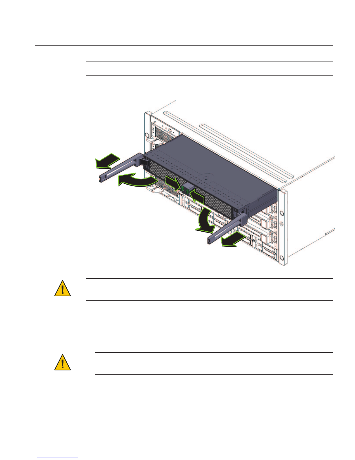
For each CPU module:
a. Pinch the green tabs to release the ejectors (1).
b. Pull both ejectors out torelease the module (2).
Caution – When the module is partway out of the chassis, close the ejectors, and grasp the
module. Do not handle the module by the ejectors.
c. Gently slide the module forward until it is clear of the chassis (3).
2
2
3
3
1
1
Installing the Server Ina Rack
15
Page 16

Caution – The CPU module is heavy. Use two hands.
d. Place the CPU module on an antistatic mat.
Remove the fourpower supplies from the front of the chassis.
a. Pinch the handle to release the lever (1).
b. Pull the lever(2) to release the power supply.
c. Slide the powersupply out of the chassis (3).
2
3
1
1
2
Installing the Server Ina Rack
Sun Fire X4800 Server Rack Mounting and Shipping Bracket User's Guide • June 201016
Page 17

Remove the PCIe express modules from the back of the chassis.
The upper bays can be used as a hand hold when moving the chassis.
a. Rotate the lever(1) to release the module.
b. Slide the module out of the chassis (2).
Remove the upperleft fan module (FM2) if necessary.
Squeeze the clamp (1) to release the fan module (2), then pull it from the chassis (3).
1
2
3
4
Installing the Server Ina Rack
17
Page 18

You can use the recess as a hand-hold when moving the chassis.
Reverse these steps to reassemble the server after it is installed in the rack.
▼
How to Install the Rack Mounting Hardware in the Rack
The rack mounting hardware consists of front and rear mounting brackets with cage nuts,
screws, and shelf rails.
1
1
3
2
5
Installing the Server Ina Rack
Sun Fire X4800 Server Rack Mounting and Shipping Bracket User's Guide • June 201018
Page 19

Caution – The server weighs about 180 pounds (100 kg) when fully loaded with components. To
reduce the risk of serious personal injury or equipment damage, use a mechanical lift to install
the server into the rack. If a lift is not available, remove components as described in
“How to
Remove Components to Reduce Weight” on page 14
. This reduces the weight of the server to 80
pounds (45 kg).
Always load equipment into a rack from the bottom up so that it does not become top-heavy
and tip over. Deploy your rack’s anti-tilt bar to prevent the rack from tipping during equipment
installation.
Verify that you havea 5RU space in your rack.
Select the two front mounting brackets that match your rack.
The server ships with two sets of front mounting brackets: one (1) for racks with round holes
and one (2) for racks with square holes. Select the brackets that match your rack.
Attach the frontbrackets to the rack.
Make sure you orient the brackets correctly, with the arrow pointing up.
Select the screws that match your rack.
■
Use one M6 per side for a square-hole rack.
■
Use three M6 or three 10-32 per side for a threaded round-hole rack.
The following gure shows the front brackets being attached to a square-hole rack (1) and a
round-hole rack (2).
1
2
1
2
3
Installing the Server Ina Rack
19
Page 20

If your rack has round holes, use the screws (1) tofasten the two rear mounting brackets (2) to
the rack.
If your rack has square holes, skip this step.
If your rackhas square holes:
a. Insert the cage nuts (1) for therear mounting bracketsin the holes on the rack.
b. If you aregoing to install shipping brackets, insert the cage nuts forthe shipping brackets(2)
in the holes in the rear of the rack.
Note the orientation of the cage nuts for the shipping bracket.
■
They face outside the rack, in the opposite direction of the cage nuts for the mounting
brackets.
■
They are located in the rst and third holes above the cage nuts for the mounting
brackets.
1
2
4
5
Installing the Server Ina Rack
Sun Fire X4800 Server Rack Mounting and Shipping Bracket User's Guide • June 201020
Page 21

Note – If you are going to install shipping brackets so you can ship your system in a rack, and
your system has a square-hole rack, you must install the rear cage nuts for the shipping
bracket on the rack now, before installing the rear mounting bracket. You cannot add the
cage nuts for the rear shipping bracket when the rear mounting brackets are in place. See
“Removing and Installing Shipping Brackets” on page 26 for instructions to install the
shipping brackets.
c. Use two screws(3) to fasten each rear bracket (4) to the rack.
Place the shelf rails into the rack.
The shelf rails expand (1) to t the rack, then slip into the slots on the mounting brackets (2),
and drop into place (3).
1
2
4
3
6
Installing the Server Ina Rack
21
Page 22

Be certain to place the shelf rails in the proper orientation, with the shelf facing inward and the
gap towards the front of the rack.
“How to Insert the Server Into the Rack” on page 23
2
1
2
3
3
Next Steps
Installing the Server Ina Rack
Sun Fire X4800 Server Rack Mounting and Shipping Bracket User's Guide • June 201022
Page 23

▼
How to Insert the ServerInto the Rack
The following procedure explains how to insert the server into the rack and on to the shelf rail
assemblies on the rack.
Perform the steps in
“How to Install the Rack Mounting Hardware in the Rack” on page 18.
Lift the server to its position on the rack.
The use of a lift is recommended.
Caution – The server weighs 180 pounds (82 kg). To reduce the risk of serious personal injury or
equipment damage, use a mechanical lift to install the server into the rack. If a lift is not
available, remove components as instructed in
“How to Remove Components to Reduce
Weight” on page 14
and use two persons to lift the server into place.
Slide the server onto the shelf rails.
Caution – Drop Hazard! Do not release the server until it is more than 6 inches (152 mm) into the
rack, and is rmly supported by the shelf rails. The shelf rails will not support the server until it
is more than 6 inches (152 mm) inside the rack.
BeforeYou Begin
1
2
Installing the Server Ina Rack
23
Page 24

6”
(152mm)
!
!
!
Installing the Server Ina Rack
Sun Fire X4800 Server Rack Mounting and Shipping Bracket User's Guide • June 201024
Page 25
Use four screwsto attach the front of the server to the front of the rack.
Use either the M6 x 25, or the 10-32 x 1 screws.
■
On a threaded rack, use four M6 x 25, or four 10-32 x 1 screws.
■
On a square-hole rack, use four M6 x 25 screws.
If you removedcomponents from the server,replace them afterit is mounted in the rack. See
“How to RemoveComponents to Reduce Weight” on page 14.
■
“How to Remove the Server From the Rack” in Sun Fire X4800 Server Installation Guide
■
“Cabling and Power” in Sun Fire X4800 Server Installation Guide
■
“How to Remove Components to Reduce Weight” on page 14
3
4
See Also
Installing the Server Ina Rack
25
Page 26

Removing and Installing Shipping Brackets
If the server is shipped in a rack, it must be supported by shipping brackets.
■
If the server is shipped to you in a rack, you must remove the brackets before placing it in
service. See
“How to Remove Shipping Brackets” on page 26.
■
If you plan to ship the server in a rack, see “How to Install the Shipping Brackets” on
page 28
.
▼
How to Remove Shipping Brackets
The shipping bracket kit consists of a front bracket, a rear bottom bracket, a rear top bracket,
screws to connect them to the rack, and cage nuts to be used with the rear brackets on racks with
square holes. These appear in
“How to Install the Shipping Brackets” on page 28.
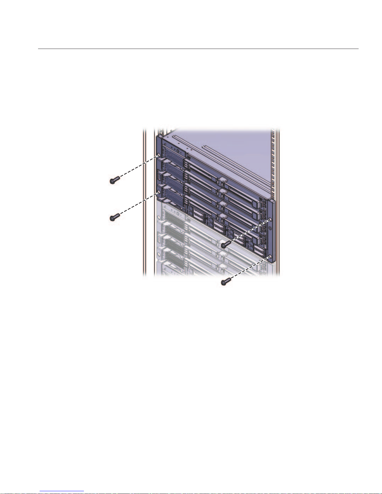
Remove the fourscrews (1) thatfasten the front bracket (2) to the frontof the server and remove
it.
1
2
1
Removing and Installing Shipping Brackets
Sun Fire X4800 Server Rack Mounting and Shipping Bracket User's Guide • June 201026
Page 27

The front shipping bracket contains eight threaded holes used for storing unused screws (four
M6 and four 10–32). Remove the screws that match the threads on your rack and use them to
secure the server to therack.
There might be two sets of screws stored on the front of the shipping bracket. Use the set that
matches the threading on your rack.
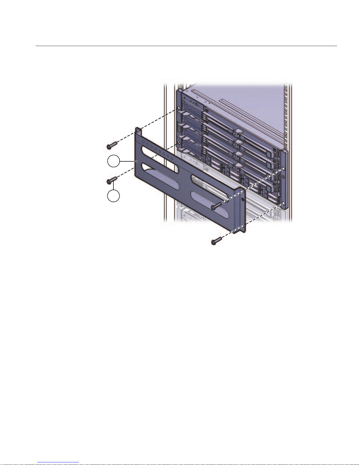
Thread the long screws that youremoved in Step 1 into the four empty holes on the shipping
bracket.
They will be stored there in case you need to reinstall the shipping bracket.
Remove the fourscrews (1) thatfasten the rear top bracket (2) over the back of theserver and
remove it.
Remove the fourscrews (3) thatfasten the rear bottom bracket (4) under the back of the server
and remove it.
1
4
2
3
2
3
4
5
Removing and Installing Shipping Brackets
27
Page 28

▼
How to Install the Shipping Brackets
The shipping bracket kit contains the following parts:
Figure Legend
1 Front shipping bracket
2, 3 Two sets of screws (M6 and 10-32). Each set contains four screws for the front shipping
bracket (2) and eight screws for the rear shipping brackets (5 and 6)
4 Eight M6 cage nuts for rear shipping bracket in square-hole racks
5 Top rear shipping bracket
6 Bottom rear shipping bracket
Remove the four(short) screwsthat fasten the front of the server to the rack.
Insert the front bracket (1) into the front of theserver with the supportingange underneath
the server.
The front shipping bracket contains eight threaded holes used for storing unused screws (four
M6 and four 10–32). Remove the long screwsthat match the threads on yourrack.
3
4
2
1
6
5
1
2
3
Removing and Installing Shipping Brackets
Sun Fire X4800 Server Rack Mounting and Shipping Bracket User's Guide • June 201028
Page 29
Use the four long screws (M6 or 10–32) (1) to fasten the shipping bracket (2) tothe front of the
server.
Insert the short screwsinto the four empty storage holes on the shipping bracket.
They will be stored there to be used when you remove the shipping bracket.
If you areinstalling the shipping brackets in a rack with square holes, check to ensure that the
cage nuts are installed in the rear.
Note the orientation and location of the cage nuts for the shipping bracket.
■
There are four cage nuts per side (eight total).
■
They are installed on the inside of the rack, facing outward. This is the opposite direction
from the cage nuts for the shelf mounting brackets.
■
For each shelf bracket cage nut, there should be two shipping bracket cage nuts; one in the
hole directly above the shelf bracket cage nut, and one in the third hole above the shelf
bracket cage nut.
If the cage nuts are not in place, you must:
a. Remove the server and the mounting hardware from the rack, as described in
“Removing
the Server From the Rack” in Sun Fire X4800 Server Installation Guide
.
1
2
4
5
6
Removing and Installing Shipping Brackets
29
Page 30

b. Reinstall the mounting brackets and the server, and install the rear shipping bracket cage
nuts as you install the rear mounting brackets.Thisis included in the rack mounting
procedure.
See
“How to Install the Rack Mounting Hardware in the Rack” on page 18.
Insert the rear top bracket(1) over theback of the server with the sidepanels facing down.
Use four screws (2) to fasten it to the rack (4).
Insert the rear bottom bracket(3) under the back of the serverwith the side panels facing up.
Use four screws (4) to fasten it to the rack.
1
2
3
4
7
8
Removing and Installing Shipping Brackets
Sun Fire X4800 Server Rack Mounting and Shipping Bracket User's Guide • June 201030
 Loading...