


Sun Dual 10GbE SFP+ PCIe
ExpressModule
User’s Guide
Part No. 820-4979-12
May 2010, Revision A

Copyright ©2008, 2010,Oracle and/orits affiliates.All rightsreserved.
This softwareand related documentationare providedunder alicense agreement containingrestrictions onuse anddisclosure andareprotected by
intellectual propertylaws. Exceptas expressly permittedin yourlicense agreementor allowedby law,you maynot use,copy,reproduce, translate,
broadcast, modify,license, transmit,distribute, exhibit,perform, publish,or displayany part,in anyform, orby anymeans. Reverseengineering,
disassembly, ordecompilation ofthis software,unless required bylaw forinteroperability, isprohibited.
The informationcontained hereinis subjectto changewithout noticeand isnot warrantedto beerror-free.If youfind anyerrors, pleasereport them tous
in writing.
If thisis softwareor related softwaredocumentation thatis deliveredto theU.S. Governmentor anyonelicensing iton behalfof theU.S. Government,the
following noticeis applicable:
U.S. GOVERNMENTRIGHTS. Programs,software, databases, and related documentationand technicaldata deliveredto U.S.Government customers
are "commercial computersoftware" or"commercial technicaldata" pursuantto theapplicable FederalAcquisition Regulationand agency-specific
supplemental regulations.As such,the use,duplication, disclosure, modification,and adaptationshall besubject tothe restrictionsand licenseterms set
forth inthe applicableGovernment contract,and, tothe extentapplicable bythe termsof theGovernment contract,the additionalrights setforth inFAR
52.227-19, CommercialComputer Software License(December 2007).Oracle America,Inc., 500Oracle Parkway,Redwood City, CA 94065.
This softwareor hardware isdeveloped forgeneral use ina varietyof informationmanagement applications.It isnot developed orintended foruse inany
inherently dangerous applications,including applicationswhich maycreate arisk ofpersonal injury.If youuse thissoftware orhardwarein dangerous
applications, thenyou shallbe responsibleto takeall appropriate fail-safe,backup, redundancy,and othermeasures toensure its safe use. Oracle
Corporation andits affiliatesdisclaim anyliability forany damagescaused byuse ofthis software orhardware indangerous applications.
Oracle andJava areregisteredtrademarks ofOracle and/orits affiliates.Other namesmay betrademarks oftheir respectiveowners.
AMD, Opteron,the AMDlogo, andthe AMDOpteron logo aretrademarks orregistered trademarksof AdvancedMicroDevices. Inteland IntelXeon are
trademarks orregistered trademarks of Intel Corporation. All SPARC trademarksare used under license and are trademarksor registeredtrademarks of
SPARCInternational, Inc.UNIX is a registered trademarklicensed throughX/Open Company,Ltd.
This software or hardware and documentation may provide access to or information on content, products, and services from third parties. Oracle
Corporation and its affiliates are not responsible for and expressly disclaim all warranties of any kind with respect to third-party content, products, and
services. Oracle Corporation and its affiliates will not be responsible for any loss, costs, or damages incurred due to your access to or use of third-party
content, products, or services.
Copyright ©2008, 2010,Oracle et/ouses affiliés.Tous droitsréservés.
Ce logicielet ladocumentation quil’accompagne sontprotégés parles loissur lapropriété intellectuelle. Ils sont concédés sous licence et soumis à des
restrictions d’utilisationet dedivulgation. Saufdisposition devotre contrat de licence ou de la loi, vous ne pouvez pas copier, reproduire, traduire,
diffuser,modifier, breveter, transmettre, distribuer, exposer, exécuter,publier ouafficher lelogiciel, mêmepartiellement, sousquelque formeet par
quelque procédéque cesoit. Parailleurs, ilest interdit deprocéder àtoute ingénierieinverse dulogiciel, dele désassemblerou dele décompiler, exceptéà
des finsd’interopérabilité avecdes logicielstiers outel queprescrit par la loi.
Les informationsfournies dansce documentsont susceptiblesde modificationsans préavis.Par ailleurs,Oracle Corporationne garantitpas qu’elles
soient exemptesd’erreurs etvous invite,le caséchéant, àlui enfaire part par écrit.
Si celogiciel, oula documentationqui l’accompagne,est concédésous licenceau Gouvernementdes Etats-Unis,ou àtoute entitéqui délivrela licencede
ce logicielou l’utilisepour lecompte duGouvernement desEtats-Unis, lanotice suivantes’applique :
U.S. GOVERNMENTRIGHTS. Programs,software, databases, and related documentationand technicaldata deliveredto U.S.Government customers
are "commercial computersoftware" or"commercial technicaldata" pursuantto theapplicable FederalAcquisition Regulationand agency-specific
supplemental regulations. As such, theuse, duplication,disclosure, modification, and adaptation shall be subject to the restrictions andlicense termsset
forth inthe applicableGovernment contract,and, tothe extentapplicable bythe termsof theGovernment contract,the additionalrights setforth inFAR
52.227-19, CommercialComputer Software License(December 2007). Oracle America, Inc.,500 OracleParkway, RedwoodCity,CA 94065.
Ce logicielou matériela étédéveloppé pourun usagegénéral dansle cadred’applications degestion desinformations. Celogiciel oumatériel n’estpas
conçu nin’est destinéà êtreutilisé dansdes applicationsà risque,notamment dansdes applicationspouvant causerdes dommagescorporels. Si vous
utilisez celogiciel oumatériel dansle cadred’applications dangereuses, ilest devotre responsabilitéde prendre toutesles mesuresde secours,de
sauvegarde, deredondance et autresmesures nécessairesà sonutilisation dansdes conditionsoptimales desécurité. OracleCorporation etses affiliés
déclinent touteresponsabilité quantaux dommagescausés parl’utilisation dece logicielou matérielpour cetype d’applications.
Oracle etJava sontdes marquesdéposées d’OracleCorporation et/oude sesaffiliés.Tout autre nommentionné peutcorrespondre àdes marques
appartenant àd’autres propriétaires qu’Oracle.
AMD, Opteron,le logoAMD etle logoAMD Opteron sontdes marquesou desmarques déposéesd’Advanced Micro Devices.Intel etIntel Xeonsont des
marques oudes marques déposéesd’Intel Corporation.Toutesles marques SPARC sontutilisées souslicence etsont desmarques ou des marques
déposées deSPARCInternational, Inc.UNIX est une marque déposéeconcédée souslicence parX/Open Company,Ltd.
Ce logicielou matérielet ladocumentation quil’accompagne peuventfournir desinformations oudes liensdonnant accèsà descontenus, desproduits et
des servicesémanant detiers. OracleCorporation etses affiliésdéclinent touteresponsabilité ou garantie expresse quantaux contenus,produits ou
services émanantde tiers.En aucuncas, OracleCorporation etses affiliésne sauraientêtre tenus pour responsables despertes subies,des coûts
occasionnés oudes dommagescausés parl’accès àdes contenus,produits ouservices tiers,ou àleur utilisation.
Please
Recycle

Contents
Regulatory Compliance Statements vii
Safety Agency Compliance Statements xi
Using This Documentation xv
1. Sun Dual 10GbE SFP+ PCIe ExpressModule Overview 1
Shipping Kit Contents 1
ExpressModule Hardware Overview 1
ExpressModule Features 2
Indicator Lights on the ExpressModule 3
Hardware and Software Requirements 5
Patches and Updates 6
2. Installing and Setting Up the Device Driver Software 7
Verifying, Installing, and Removing the Driver on a Solaris Platform 7
▼ To Check the Driver Version on a Solaris Platform 8
▼ To Install the Driver for a Solaris Platform 8
▼ To Remove the Driver for a Solaris Platform 8
Downloading, Installing and Removing the Driver on a Linux Platform 8
▼ To Download the Driver for a Linux Platform 9
iii

▼ To Install the Driver for a Linux Platform 9
▼ To Remove the Driver From a Linux Platform 10
Downloading, Installing and Removing the Driver on a Microsoft Windows
Platform 11
▼ To Download andInstall the Driveron a Microsoft Windows Platform 11
▼ To Remove the Driver From a Microsoft Windows Platform 12
3. Installing the ExpressModule 13
Installing an Optical Transceiver 13
▼ To Install an Optical Transceiver 13
Installing the ExpressModule 16
▼ To Install the ExpressModule With the Power Off 16
Verifying the Installation 19
▼ To Verify the Installation on a Solaris System 19
▼ To Verify the Installation in a Linux System 20
▼ To Verify the Installation in a Microsoft Windows System 20
4. Network Configuration 21
Configuring the Network Host Files for a Solaris System 21
▼ To Configure the Network Host Files by Creating
/etc/hostname.ixgbe# Files 22
▼ To Configure the Network Host Files Using the ifconfig Command 22
▼ To Boot Over the Network using PXE 23
Configuring the Network Host Files for Booting Over the Gigabit Ethernet
Network for Linux Systems 23
▼ To Boot Over the Network on Linux Systems 23
5. Configuring the Driver Parameters 25
Driver Overview 25
Driver Parameters for Solaris 26
Setting ixgbe Driver Parameters in Solaris 27
iv Sun Dual 10GbE SFP+ PCIe ExpressModule User’s Guide • May 2010

▼ To set driver parameters using the ixgbe.conf file 27
Improving Performance in Solaris 28
▼ To improve performance in the case of large numbers of connections and
packets 28
Driver Parameters for Linux Systems 29
Setting ixgbe Driver Parameters in Linux Systems 30
▼ To Configure Jumbo Frames 30
6. Configuring Link Aggregation 31
Link Aggregation Overview 31
Configuring Link Aggregation in a Solaris Environment 32
▼ To Configure Link Aggregations 32
▼ To Display Information About Link Aggregations 33
▼ To Delete Link Aggregations 33
7. Configuring VLANs 35
VLAN Overview 35
Configuring VLANs 38
▼ To Configure Static VLANs in a Solaris Environment 39
▼ To Configure VLANs in a Linux Environment 40
▼ To Configure VLANs in a Microsoft Windows 2003 Environment 41
Configuring Bonding for Multiple Interfaces 42
▼ To Configure Bonding for Multiple ixgbe Interfaces 42
▼ To Remove Bonding 42
A. Sun Dual 10GbE SFP+ PCIe ExpressModule Specifications 45
Connectors 46
Table lists the card’s operating range.Technical Features 47
Physical Characteristics 47
Power and Environmental Requirements 48
Contents v

Index 49
vi Sun Dual 10GbE SFP+ PCIe ExpressModule User’s Guide • May 2010

Regulatory Compliance Statements
Your Sun product is marked to indicate its compliance class:
• Federal Communications Commission (FCC) — USA
• Industry Canada Equipment Standard for Digital Equipment (ICES-003) — Canada
• Voluntary Control Council for Interference (VCCI) — Japan
• Bureau of Standards Metrology and Inspection (BSMI) — Taiwan
Please read the appropriate section that corresponds to the marking on your Sun product before attempting to install the
product.
FCC Class A Notice
This device complies with Part 15 of the FCC Rules. Operation is subject to the following two conditions:
1. This device may not cause harmful interference.
2. This device must accept any interference received, including interference that may cause undesired operation.
Note: This equipment has been tested and found to comply with the limits for a Class A digital device, pursuant to Part 15 of
the FCC Rules. These limits are designed to provide reasonable protection against harmful interference when the equipment
is operated in a commercial environment. This equipment generates, uses, and can radiate radio frequency energy, and if it is
not installed and used in accordance with the instruction manual, itmay cause harmful interference to radio communications.
Operation of this equipment in aresidential area is likely to cause harmful interference, in which case theuser will be required
to correct the interference at his own expense.
Modifications: Any modifications made to thisdevice thatare notapproved by Sun Microsystems, Inc.may voidthe authority
granted to the user by the FCC to operate this equipment.
ICES-003 Class A Notice - Avis NMB-003, ClasseA
This Class A digital apparatus complies with Canadian ICES-003.
Cet appareil numérique de la classe A est conforme à la norme NMB-003 du Canada.
vii

BSMI Class A Notice
The following statement is applicable to products shipped to Taiwan and marked as Class A on the product compliance
label.
T33012
CCC Class A Notice
The following statement is applicable to products shipped to China and marked with “Class A” on the product’s compliance
label.
GOST-R Certification Mark
viii Sun Dual 10GbE SFP+ PCIe ExpressModule User’s Guide • May 2010

Declaration of Conformity
Compliance Model Number: 5945532
Product Family Name: Sun Dual 10GbE SFP+ PCIe ExpressModule
EMC
USA—FCC Class A
This equipment complies with Part 15 of the FCC Rules. Operation is subject to the following two conditions:
1. This equipment may not cause harmful interference.
2. This equipment must accept any interference that may cause undesired operation.
Canada
This Class A digital apparatus complies with Canadian ICES-003.
European Union
This equipment complies with the following requirements of the EMC Directive 2004/108/EC:
As Information Technology Equipment (ITE) Class A per (as applicable):
EN 55022:2006 Class A
EN 61000-3-2:2000 +A2:2005 Pass
EN 61000-3-3:1995 +A1:2001 Pass
EN 55024:1998 +A1:2001 +A2:2003 Required Limits:
IEC61000-4-2 4 kV (Direct), 8 kV (Air)
IEC61000-4-3 3 V/m
IEC61000-4-4 1 kV AC Power Lines, 0.5 kV Signal and DC Power Lines
IEC61000-4-5 1 kV AC Line-Line and Outdoor Signal Lines, 2 kV AC Line-Gnd, 0.5 kV DC Power Lines
IEC61000-4-6 3 V
IEC61000-4-8 1 A/m
IEC61000-4-11 Pass
Safety
This equipment complies with the following requirements of the Low Voltage Directive2006/95/EC:
EC Type Examination Certificates:
EN 60950-1:2001, 1st Edition
IEC 60950-1:2001, 1st Edition CB Scheme Certificate No. NO47596
Evaluated to all CB Countries
UL 60950-1:2003, CSA C22.2 No. 60950-03 File: E139761 Vol. 7
Supplementary Information
This equipment was tested and complies with all the requirements for the CE Mark.
This equipment complies with the Restriction of Hazardous Substances (RoHS) directive 2002/95/EC.
.
/S/
Dennis P. Symanski DATE
Worldwide Compliance Office
Sun Microsystems, Inc.
4150 Network Circle, MPK15-102
Regulatory Compliance Statements ix

Santa Clara, CA 95054 U.S.A.
Tel: 650-786-3255 Fax: 650-786-3723
x Sun Dual 10GbE SFP+ PCIe ExpressModule User’s Guide • May 2010

Safety Agency Compliance Statements
Read this section before beginning any procedure. The
following text provides safety precautions to follow when
installing a Sun Microsystems product.
Safety Precautions
For your protection, observe the following safety
precautions when setting up your equipment:
■ Follow all cautions and instructions marked on the
equipment.
■ Ensure that the voltage and frequency of your power
source match the voltage and frequency inscribed on
the equipment’s electrical rating label.
■ Never push objects of any kind through openings in
the equipment. Dangerous voltages may be present.
Conductive foreign objects could produce a short
circuit that could cause fire, electric shock, or damage
to your equipment.
Symbols
The following symbols may appear in this book:
Caution – There is a risk of personal injury
and equipment damage. Follow the
instructions.
Depending on the type of power switch your device has,
one of the following symbols may be used:
On – Applies AC power to the system.
Off – Removes AC power from the system.
Standby – The On/Standby switch is in the
standby position.
Modifications to Equipment
Do not make mechanical or electrical modifications to the
equipment. Sun Microsystems is not responsible for
regulatory compliance of a modified Sun product.
Placement of a Sun Product
Caution – Do not block or cover the openings
of your Sun product. Never place a Sun
product near a radiator or heat register.
Failure to follow these guidelines can cause
overheating and affect the reliability of your
Sun product.
Caution – Hot surface. Avoid contact.
Surfaces are hot and may cause personal
injury if touched.
Caution – Hazardous voltages are present. To
reduce the risk of electric shock and danger to
personal health, follow the instructions.
System Unit Cover
You must remove the cover of your Sun computer system
unit to add cards, memory, or internal storage devices. Be
sure toreplace thecover beforepowering onyour computer
system.
Caution – Do not operate Sun products
without the cover in place. Failure to take this
precaution may result in personal injury and
system damage.
xi

Conformité aux normes de sécurité
Veuillez lire attentivement cette section avant de
commencer. Ce texte traite des mesures de sécurité qu’il
convient de prendre pour l’installation d’un produit Sun
Microsystems.
Mesures de sécurité
Pour votre sécurité, nous vous recommandons de suivre
scrupuleusement lesmesures de sécurité ci-dessous lorsque
vous installez votre matériel:
■ Suivez tous les avertissements et toutes les
instructions inscrites sur le matériel.
■ Assurez-vous que la tension et la fréquence de votre
source d'alimentation correspondent à la tension et à
la fréquence indiquées sur l'étiquette de la tension
électrique nominale du matériel
■ N'introduisez jamais d'objets quels qu'ils soient dans
les ouvertures de l'équipement. Vous pourriez vous
trouver en présence de hautes tensions dangereuses.
Tout objet étranger conducteur risque de produire un
court-circuit pouvant présenter un risque d'incendie
ou de décharge électrique, ou susceptible
d'endommager le matériel.
Symboles
Vous trouverez ci-dessous la signification des différents
symboles utilisés:
Attention – Vous risquez d'endommager le
matériel ou de vous blesser. Veuillez suivre les
instructions.
Attention – Surfaces brûlantes. Evitez tout
contact. Les surfaces sont brûlantes. Vous
risquez de vous blesser si vous les touchez.
Attention – Tensions dangereuses. Pour
réduire les risques de décharge électrique et
de danger physique, observez les consignes
indiquées.
Marche – Met le système sous tension
alternative.
Arret – Met le système hors tension
alternative.
Veilleuse – L'interrupteur Marche/Veille est
sur la position de veille.
Modification du matériel
N'apportez aucune modification mécanique ou électrique
au matériel. Sun Microsystems décline toute responsabilité
quant à la non-conformité éventuelle d'un produit Sun
modifié.
Positionnement d’un produit Sun
Attention – Evitez d'obstruer ou de recouvrir
les orifices de votre produit Sun. N'installez
jamais un produit Sun près d'un radiateur ou
d'une source de chaleur. Si vous ne respectez
pas ces consignes, votre produit Sun risque de
surchauffer et son fonctionnement en sera
altéré.
Couvercle de l'unité
Pour ajouterdes cartes, de la mémoire ou despériphériques
de stockage internes, vous devez retirer le couvercle de
votre système Sun. Remettez le couvercle supérieur en
place avant de mettre votre système sous tension.
Attention – Ne mettez jamais des produits
Sun sous tension si leur couvercle supérieur
n'est pas mis en place. Si vous ne prenez pas
ces précautions, vous risquez de vous blesser
ou d'endommager le système.
Selon le type d'interrupteur marche/arrêt dont votre
appareil est équipé, l'un des symboles suivants sera utilisé:
xii Sun Dual 10GbE SFP+ PCIe ExpressModule User’s Guide • May 2010

Einhaltung sicherheitsbehördlicher Vorschriften
Lesen Sie vor dem Ausführen von Arbeiten diesen
Abschnitt. Im folgenden Text werden Sicherheitsvorkehrungen beschrieben, die Sie bei der Installation eines
Sun Microsystems-Produkts beachten müssen.
Sicherheitsvorkehrungen
Treffen Sie zu Ihrem eigenen Schutz bei der Installation des
Geräts die folgenden Sicherheitsvorkehrungen:
■ Beachten Sie alle auf den Geräten angebrachten
Warnhinweise und Anweisungen.
■ Stellen Sie sicher, dass Spannung und Frequenz der
Stromversorgung den Nennleistungen auf dem am
Gerät angebrachten Etikett entsprechen.
■ Führen Sie niemals Fremdobjekte in die Öffnungen
am Gerät ein. Es können gefährliche Spannungen
anliegen. Leitfähige Fremdobjekte können einen
Kurzschluss verursachen, der einen Brand, Stromschlag oder Geräteschaden herbeiführen kann.
Aus– Unterbricht die Wechselstromzufuhr
zum Gerät.
Wartezustand – Der Ein-/Standby-Netzschalter befindet sich in der Standby-Position.
Modifikationen des Geräts
Nehmen Sie keine elektrischen oder mechanischen
Gerätemodifikationen vor. Sun Microsystems ist für die
Einhaltung der Sicherheitsvorschriften von modifizierten
Sun-Produkten nicht haftbar.
Gehäuseabdeckung
Sie müssen die Abdeckung Ihres Sun-Computersystems
entfernen, um Karten, Speicher oderinterne Speichergeräte
hinzuzufügen. Bringen Sie vor dem Einschalten des
Systems die Gehäuseabdeckung wieder an.
Symbole
Die Symbole in diesem Handbuch haben folgende
Bedeutung:
Achtung – Gefahr von Verletzung und
Geräteschaden. Befolgen Sie die Anweisungen.
Achtung – Heiße Oberfläche. Nicht berühren,
da Verletzungsgefahr durch heiße Oberfläche
besteht.
Achtung – Gefährliche Spannungen. Befolgen
Sie die Anweisungen, um Stromschläge und
Verletzungen zu vermeiden.
Je nach Netzschaltertyp an Ihrem Gerät kann eines der
folgenden Symbole verwendet werden:
Ein – Versorgt das System mit Wechselstrom.
Achtung – Nehmen Sie Sun-Geräte nicht ohne
Abdeckung in Betrieb. Die Nichtbeachtung
dieses Warnhinweises kann Verletzungen oder
Geräteschaden zur Folge haben.
Safety Agency Compliance Statements xiii

Normativas de seguridad
Lea esta sección antes de realizar cualquier operación. En
ella se explican las medidasde seguridad quedebe tomar al
instalar un producto de Sun Microsystems.
Apagado – Corta la alimentación de CA del
sistema.
Medidas de seguridad
Para su protección, tome las medidas de seguridad
siguientes durante la instalación del equipo:
■ Siga todos los avisos e instrucciones indicados en el
equipo.
■ Asegúrese de que el voltaje y frecuencia de la fuente
de alimentación coincidan con el voltaje y frecuencia
indicados en la etiqueta de clasificación eléctrica del
equipo.
■ No introduzca objetos de ningún tipo por las rejillas
del equipo, ya que puede quedar expuesto a voltajes
peligrosos. Los objetos conductores extraños pueden
producir cortocircuitos y, en consecuencia, incendios,
descargas eléctricas o daños en el equipo.
Símbolos
En este documento aparecen los siguientes símbolos:
Precaución – Existe el riesgo de que se
produzcan lesiones personales y daños en el
equipo. Siga las instrucciones.
Precaución – Superficie caliente. Evite todo
contacto. Las superficies están calientes y
pueden causar lesiones personales si se tocan.
Espera – El interruptor de encendido/espera
está en la posición de espera.
Modificaciones en el equipo
No realicemodificaciones detipo mecániconi eléctricoen el
equipo. Sun Microsystems no se hace responsable del
cumplimiento de normativas en caso de que un producto
Sun se haya modificado.
Colocación de un producto Sun
Precaución – No obstruya ni tape las rejillas
del producto Sun. Nunca coloque un producto
Sun cerca de radiadores ni fuentes de calor. Si
no sigue estas indicaciones, el producto Sun
podría sobrecalentarse y la fiabilidad de su
funcionamiento se vería afectada.
Precaución – Voltaje peligroso. Para reducir
el riesgo de descargas eléctricas y lesiones
personales, siga las instrucciones.
En función del tipo de interruptor de alimentación del que
disponga el dispositivo, se utilizará uno de los símbolos
siguientes:
Encendido – Suministra alimentación de CA
al sistema.
xiv Sun Dual 10GbE SFP+ PCIe ExpressModule User’s Guide • May 2010

Using This Documentation
This user’s guide provides hardware and software installation instructions for
Oracle’s Sun Dual 10GbE SFP+ PCIe Express Module.
This document also describes how to configure the driver software for the ixgbe
driver for Solaris, Linux, and Microsoft Windows Server 2003 operating systems.
These instructions are designed for enterprise system administrators with experience
installing network hardware and software.
Note – In this document the term x86 refers to 64-bit and 32-bit systems
manufactured using processors compatible with the SPARC, AMD64, Intel Xeon, or
Intel Pentium product families.
xv

Related Documentation
Online documents specific to this product are available at:
http://docs.sun.com/app/docs/prod/dual.sfp.pcie
Application Title Part Number Format Location
Release Notes Sun 10GbE XFP SR PCI Express Card, Sun Dual
10GbE XFP 2 SR PCI Express Card, and Sun Dual
10GbE SFP+ PCIe ExpressModule Release Notes
820-4505 PDF
HTML
Online
Documentation, Support, and Training
These web sites provide additional resources:
■ Documentation http://docs.sun.com/
■ Support http://www.sun.com/support/
■ Training http://www.sun.com/training/
Documentation Feedback
Submit comments about this document by clicking the Feedback[+] link at
http://docs.sun.com. Include the title and part number of your document with
your feedback:
Sun Dual 10GbE SFP+ PCIe ExpressModule User’s Guide, part number 820-4979-12.
xvi Sun Dual 10GbE SFP+ PCIe ExpressModule User’s Guide • May 2010

CHAPTER
1
Sun Dual 10GbE SFP+ PCIe ExpressModule Overview
This chapter describes the Sun 10GbE XFP SR PCI Express Card hardware and
software, and includes the following sections:
■ “Shipping Kit Contents” on page 1
■ “ExpressModule Hardware Overview” on page 1
■ “Hardware and Software Requirements” on page 5
■ “Patches and Updates” on page 6
Shipping Kit Contents
The carton in which your Sun 10GbE XFP SR PCI Express Card was shipped should
contain the following items:
■ Sun 10GbE XFP SR PCI Express Card
■ Sun Dual 10GbE SFP+ PCIe ExpressModule Getting Started Guide
■ Safety and Compliance Manual
ExpressModule Hardware Overview
The Sun 10GbE XFP SR PCI Express Card is a 10 Gigabit Ethernet (10GbE) fiber
network interface card (NIC) for PCI Express systems. The ExpressModule is based
on the dual-port Intel 82598EB 10GbE controller.
1

The ExpressModule is optimized for Intel I/O Acceleration Technology (I/OAT),
which is designed to optimize network I/O. The ExpressModule is a highperformance, highly integrated 10 Gigabit Ethernet LAN card with PCIe host
interface and fiber LAN connectors on the optical modules.
The product conforms to the IEEE 802.3 standard and supports standards for system
manageability and power management.
FIGURE 1-1 Sun Dual 10GbE SFP+ PCIe ExpressModule, shown unpopulated. See also
FIGURE 3-1 and FIGURE 3-2, which show a populated transceiver.
ExpressModule Features
The Sun 10GbE XFP SR PCI Express Card provides the following features and
benefits:
■ Intel 82598EB 10 Gigabit Ethernet controller
■ Load balancing on multiple CPUs
■ Intel I/O Acceleration Technology (I/OAT)
■ iSCSI remote boot support
■ MSI-X support
■ Virtual Machine Device queues (VMDq)
■ Low latency
■ Optimized queues – 32 transmit (Tx) and 64 receive (Rx) per port
2 Sun Dual 10GbE SFP+ PCIe ExpressModule User’s Guide • May 2010

■ Support for most network operating systems (NOS)
■ Remote management support
■ Support for SFP+ form factor transceivers
■ RoHS compliant, lead-free technology
■ Intel PROSet Utility for Windows Device Manager
Indicator Lights on the ExpressModule
On the front panel of the ExpressModule (shown in FIGURE 1-2) next to each port,
there are viewing holes for two lights dedicated to that port.
meaning of the lights for each port.
TABLE 1-1 explains the
Chapter 1 Sun Dual 10GbE SFP+ PCIe ExpressModule Overview 3
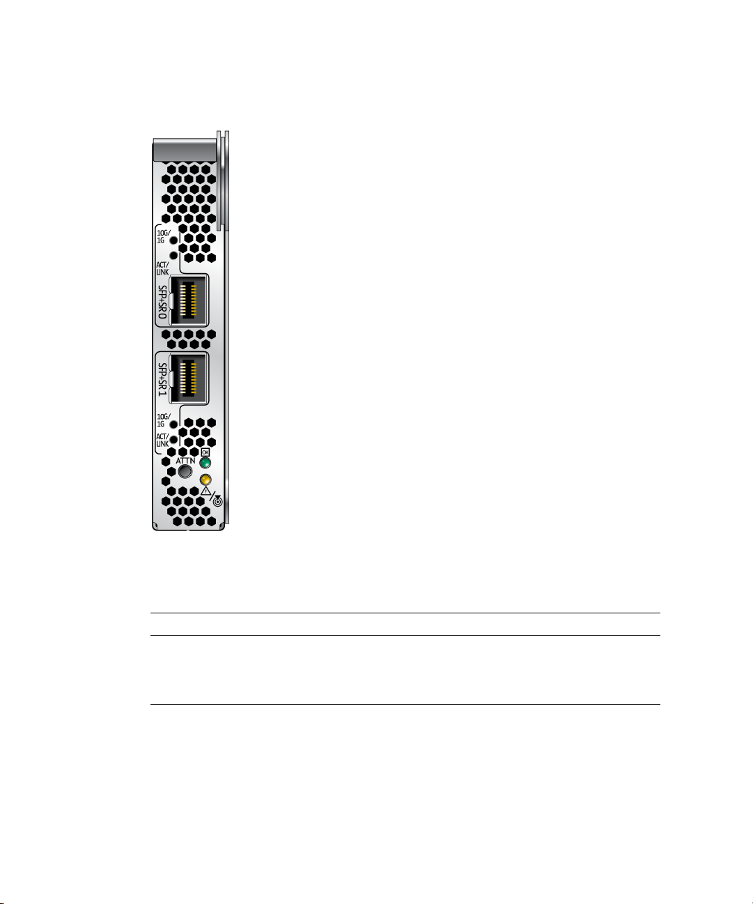
FIGURE 1-2 Front Panel Lights and Attention Switch on a transceiver, shown
unpopulated. See also
FIGURE 3-1 and FIGURE 3-2, which show a populated
transceiver.
TABLE 1-1 Indicator Lights for Each Port on the ExpressModule
Label Color Meaning
ACT/LINK Green Activity
10G/1G Green 10GbE link
10G/1G Amber 1GbE link
4 Sun Dual 10GbE SFP+ PCIe ExpressModule User’s Guide • May 2010

Two LEDs are on the ExpressModule next to the Attention switch. One LED emits
green light, the LED other emits amber light. Each light can be on, off, or blinking.
TABLE 1-2 explains the meaning of these lights.
TABLE 1-2 LED Indicator Lights on the ExpressModule
LED Color LED State Meaning Action
Green Off Power off Insertion or removal of add-in cards is
permitted. All supply voltages (except Vaux)
have been removed from the slot if required
for add-in card removal.
Green On Power on The slot is powered on. Insertion or removal of
add-in cards is not permitted.
Green Blinking Power
transition
The slot is in the process of powering up or
down. Insertion of removal of add-in cards is
not permitted.
Amber Off Normal Operation is normal.
Amber On Attention There is an operation problem at this slot.
Amber Blinking Locate This slot is being identified at user request.
Note – The Attention switch currently is not supported.
Chapter 1 Sun Dual 10GbE SFP+ PCIe ExpressModule Overview 5

Hardware and Software Requirements
Before using the Sun 10GbE XFP SR PCI Express Card, ensure that your system
meets the hardware and software requirements in
TABLE 1-3 Hardware and OS Requirements
TABLE 1-3.
Supported Hardware
and Operating
Systems
Hardware, SPARCbased
Hardware, other Sun Blade X6240 Server Module
Operating system Solaris OS – See the ExpressModule Release
* The Sun Blade X6450 Server Module supports only Solaris and Linux operating
systems.
Supported Products
Sun SPARC Enterprise X6300 Server
Sun SPARC Enterprise X6340 Server
Sun SPARC Enterprise X6450 Server
Sun Blade X6250 Server Module
Sun Blade X6440 Server Module
Sun Blade X6450 Server Module
Notes for the latest information about Solaris
OS support.
Red Hat Enterprise Linux 5.1 (32-bit and 64-bit)
Red Hat Enterprise Linux 4.6 (32-bit and 64-bit)
SUSE 10-Sp1 (64-bit)
Microsoft Windows 2008 (32-bit and 64-bit)
Microsoft Windows 2003 (32-bit and 64-bit)
*
Note that hardware and software support changes over time. For the latest
information concerning I/O options supported by your server, check:
http://www.sun.com
6 Sun Dual 10GbE SFP+ PCIe ExpressModule User’s Guide • May 2010

Patches and Updates
Check the Sun Update Connection to ensure that you have the latest recommended
patch clusters and security patches. You can download the latest recommended
patch clusters and security patches at:
http://sunsolve.sun.com/pub-cgi/show.pl?target=patchpage
Search for keyword ixgbe.
In addition:
■ Check the product site at:
http://www.sun.com/products/networking/ethernet.jsp
■ To download the most recent drivers for the Solaris OS, go to:
http://www.sun.com/download
■ To download the most recent drivers for Windows or a Linux OS, go to:
http://www.intel.com/support/network/adapter
Chapter 1 Sun Dual 10GbE SFP+ PCIe ExpressModule Overview 7

CHAPTER
2
Installing and Setting Up the Device Driver Software
The ixgbe device driver software comes bundled with Solaris software. This
chapter explains how to verify the ixgbe device driver software is present on an x86
or SPARC system that uses the Solaris OS, and how to download and install the
ixgbe driver on Solaris, Linux and Microsoft Windows systems. This chapter
contains the following sections:
■ “Verifying, Installing, and Removing the Driver on a Solaris Platform” on page 7
■ “Downloading, Installing and Removing the Driver on a Linux Platform” on
page 8
■ “Downloading, Installing and Removing the Driver on a Microsoft Windows
Platform” on page 11
Verifying, Installing, and Removing the Driver on a Solaris Platform
Note – Please see the latest Release Notes for information about which versions of
the Solaris OS support the driver for this product.
The driver for this product comes bundled with the versions of the Solaris OS that
support it. Therefore, downloading of the driver is not required.
Check the version of the driver to ensure the Sun PCI Express card is properly
loaded and is recognized by the Solaris OS.
7

▼ To Check the Driver Version on a Solaris
Platform
● Check that the version of the ixgbe driver is no older than 1.0.4:
modinfo | grep ixgbe
226 fffffffff3f0f000 151b8 67 1 ixgbe (Intel 10Gb Ethernet 1.0.4)
Note – If the version number is older than 1.0.4, you must install the latest driver
patch. See “Patches and Updates” on page 6.
▼ To Install the Driver for a Solaris Platform
The driver comes bundled with the Solaris OS. However, check for and install the
latest patches.
● Apply the necessary patch to get the latest driver.
# patchadd /absolute_path/patchID
See patchadd(1M).
▼ To Remove the Driver for a Solaris Platform
● Remove the driver.
# pkgrm SUNWixgbe
See pkgrm(1M).
Downloading, Installing and Removing the Driver on a Linux Platform
If your system uses the RedHat or SuSe Linux operating system, you must
download the ixgbe device driver to install it.
8 Sun Dual 10GbE SFP+ PCIe ExpressModule User’s Guide • May 2010

▼ To Download the Driver for a Linux Platform
1. Log in to your system.
2. With a browser, go to this location:
http://support.intel.com/support/network/adapter/10gbe/srdualserverxpr/
3. Select the following product:
Intel 10 Gigabit XF SR Dual Port ExpressModule
4. Select this option:
Download drivers and software
5. Select Linux as the operating system.
6. Locate the following driver and select Download:
Network Adapter Driver for 10 GbE PCI-E Based Network Connections for Linux
7. Review and accept the software license agreement.
8. Select this option:
Download Network Adapter Driver for 10 GbE PCI-E Based Network
Connections for Linux
The download begins. The file named ixgbe-x.x.x.x.tar.gz is saved in the
~/Desktop directory of your system.
Note – The primary driver link is buildable source archive that works with Linux
2.6.x kernels only and requires that the currently running kernel match the SRC RPM
kernel files and headers in order to build the driver. See the bundled README file
in the unpacked archive from Intel for more information.
▼ To Install the Driver for a Linux Platform
For this procedure, assume the file is file is named ixgbe-1.3.16.1.tar.gz. The
actual file might have different version or subversion numbers.
1. Copy the file containing the driver from ~/Desktop to /temp.
2. Uncompress and untar the file.
# tar -zxvf ixgbe-1.3.16.1.tar.gz
Chapter 2 Installing and Setting Up the Device Driver Software 9

3. Go to the newly created src directory:
# cd /temp/ixgbe-1.3.16.1/src
4. Compile the driver source file with these commands:
# make
# make install
5. Load the ixgbe driver with the modprobe command:
# modprobe ixgbe
6. Verify that the ixgbe driver has been successfully installed with this lsmod
command:
# lsmod | grep ixgbe
The output should be similar to the following:
ixgbe 118052 0
7. Check the ixgbe driver version with this modinfo command:
# modinfo ixgbe | grep ver
For example, the output might be the following:
filename: /lib/modules/2.6.18-53.el5/kernel/drivers/net/ixgbe/ixgbe.ko
version: 1.3.16.1-lro
description: Intel(R) 10 Gigabit PCI Express Network Driver
srcversion: 5CFF6AEBA251050F8A4B746
vermagic: 2.6.18-53.el5 SMP mod_unload gcc-4.1
▼ To Remove the Driver From a Linux Platform
● Use the rmmod command:
# rmmod ixgbe
10 Sun Dual 10GbE SFP+ PCIe ExpressModule User’s Guide • May 2010

Downloading, Installing and Removing the Driver on a Microsoft Windows Platform
If your system uses the Microsoft Windows Server 2003 operating system, perform
the following procedures to download and install the device driver.
▼ To Download and Install the Driver on a
Microsoft Windows Platform
1. Log in to your system.
2. With a browser, go to this location:
http://support.intel.com/support/network/adapter/10gbe/srdualserverxpr/
3. Select the following product:
Intel 10 Gigabit XF SR Dual Port ExpressModule
4. Select this option:
Download drivers and software
5. Select one of the following as the operating system:
■ For a 64-bit driver: Windows Server 2003 Standard x64 Edition
■ For a 32-bit driver: Windows Server 2003 Standard Edition
6. Locate one of the following and select Download next to it:
■ For a 64-bit driver: Network Adapter Driver for Windows XP Professional x64
Edition or Windows Server 2003 x64 Edition
■ For a 32-bit driver: Network Adapter Drivers for Windows 2000, Windows XP,
and Windows Server 2003
7. Review and accept the software license agreement.
8. Select one of the following to start the download:
■ Download Network Adapter Driver for Windows XP Professional x64 Edition
or Windows Server 2003 x64 Edition
Chapter 2 Installing and Setting Up the Device Driver Software 11

■ Download Network Adapter Drivers for Windows 2000, Windows XP, and
Windows Server 2003
The download begins.
9. Click on the following exe files to install the driver:
■ For a 64-bit driver: PROEM64T.exe
■ For a 32-bit driver: PRO2KXP.exe
10. Follow the instructions in the installation wizard.
11. If the Found New Hardware Wizard screen is displayed, click Cancel.
The autorun automatically runs after you have extracted the files.
▼ To Remove the Driver From a Microsoft
Windows Platform
1. From the Control Panel, double-click Add/Remove Programs.
2. Select Intel PRO Network Connections Drivers.
3. Click Add/Remove.
4. When the confirmation dialog displays, click OK.
12 Sun Dual 10GbE SFP+ PCIe ExpressModule User’s Guide • May 2010

CHAPTER
3
Installing the ExpressModule
This chapter describes how to install the ExpressModule in your system and verify
that it is recognized by the operating system.
This chapter contains the following sections:
■ “Installing an Optical Transceiver” on page 13
■ “Installing the ExpressModule” on page 16
■ “Verifying the Installation” on page 19
Installing an Optical Transceiver
The Sun 10GbE XFP SR PCI Express Card requires a short-range optical transceiver
in at least one port to create an Ethernet connection. The short-range optical
transceiver (part number X5561A-Z) is available from Sun Microsystems.
Note – Install the optical transceivers into the ExpressModule before installing the
ExpressModule into the system.
▼ To Install an Optical Transceiver
1. Pull the locking handle into the full horizontal position.
You will feel the handle click into position when it is fully opened.
13

FIGURE 3-1 Opening the Transceiver Handle
2. Holding the optical transceiver by the edges, align the transceiver with the slot
in the ExpressModule and slide the transceiver into the opening.
3. Applying even pressure at both corners of the transceiver, push the transceiver
until it is firmly seated in the slot.
4. Push the handle closed to lock the optical transceiver in place.
14 Sun Dual 10GbE SFP+ PCIe ExpressModule User’s Guide • May 2010

FIGURE 3-2 Closing the Transceiver Handle
5. Repeat Step 1 through Step 4 to install the second optical transceiver.
Caution – If you pull the locking handle down when the optical transceiver is
installed, remove the optical transceiver entirely and reinstall it. The handle operates
an internal lock. Pulling the handle down can disconnect the optical transceiver,
even though it might appear to be connected.
Chapter 3 Installing the ExpressModule 15

Installing the ExpressModule
The following instructions describe the basic tasks required to install the
ExpressModule. Refer to your system installation or service manual for detailed
ExpressModule installation instructions.
Note – To maintain proper cooling for the ExpressModule in your chassis, all
ExpressModule slots must be filled with either operating ExpressModules or filler
panels.
▼ To Install the ExpressModule With the Power
Off
1. Halt and power off your system.
2. Power off all peripherals connected to your system.
3. Attach the adhesive copper strip of the antistatic wrist strap to the metal casing
of the power supply. Wrap the other end twice around your wrist, with the
adhesive side against your skin.
4. Remove the filler panel from the ExpressModule opening.
5. Open the latch on the ExpressModule.
16 Sun Dual 10GbE SFP+ PCIe ExpressModule User’s Guide • May 2010
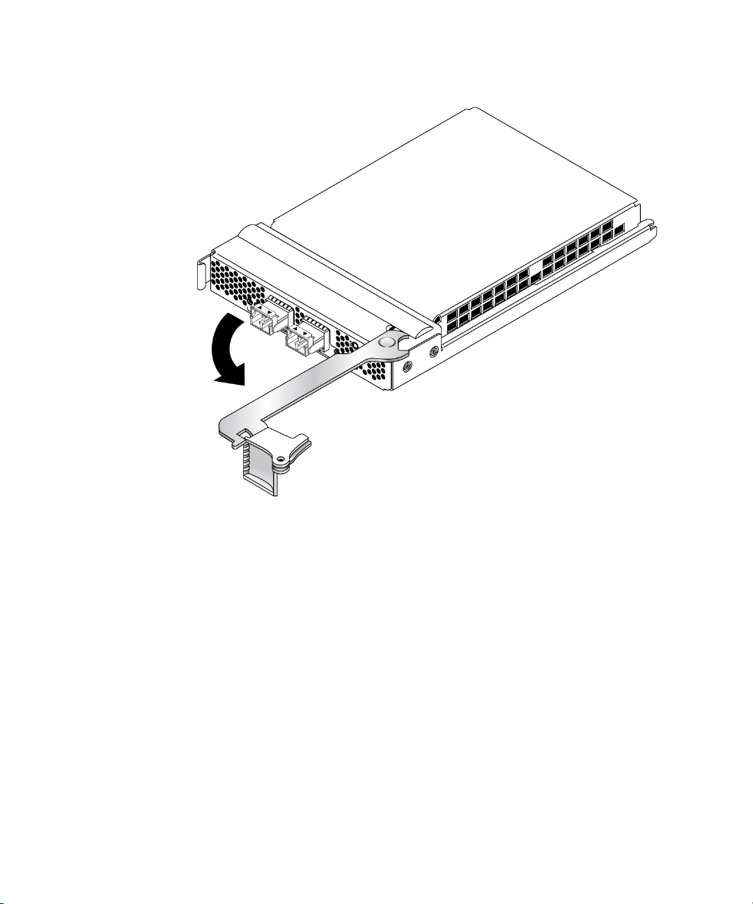
FIGURE 3-3 Opening the ExpressModule Latch
6. Align the ExpressModule with the vacant ExpressModule slot (1 in the
following figure).
Ensure that the ExpressModule’s indicator lights on the front panel are facing
toward you and that the ExpressModule ejector lever on the bottom is fully
opened.
Chapter 3 Installing the ExpressModule 17

FIGURE 3-4 Aligning the ExpressModule and Slot
7. Slide the ExpressModule into the vacant ExpressModule chassis slot until the
ejector lever engages and starts to close (2 in the preceding figure).
Failure to align the ExpressModule correctly can result in damage with the
ExpressModule’s internal connection to the chassis midplane.
8. Complete the installation by closing the ejector lever until the latch snaps into
place (3 in the preceding figure).
Caution – Do not use excessive force when installing the ExpressModule into the
slot. You might damage the ExpressModule’s connector. If the ExpressModule does
not seat properly when you apply even pressure, remove and carefully reinstall the
ExpressModule.
9. Detach the wrist strap.
10. Connect the Ethernet cables.
18 Sun Dual 10GbE SFP+ PCIe ExpressModule User’s Guide • May 2010

FIGURE 3-5 Connecting the Ethernet Cables
Verifying the Installation
After you have installed the Sun 10GbE XFP SR PCI Express Card, perform the
following tasks to verify the installation.
▼ To Verify the Installation on a Solaris System
1. Power on the system.
2. Check the driver version on your system.
# modinfo|grep ixgbe
226 fffffffff3f0f000 151b8 67 1 ixgbe (Intel 10Gb Ethernet 1.0.4)
Chapter 3 Installing the ExpressModule 19

3. Check to see if the card is properly installed and recognized by the OS:
# grep ixgbe /etc/path_to_inst
If the card is properly installed, you will see output similar to the following:
"/pci@0,0/pci10de,376@a/pci108e,f35f@0" 0 "ixgbe"
"/pci@79,0/pci10de,376@a/pci108e,f25f@0" 1 "ixgbe"
"/pci@79,0/pci10de,376@a/pci108e,f25f@0,1" 2 "ixgbe"
▼ To Verify the Installation in a Linux System
● Verify the new network interface instances corresponding to the Sun 10GbE
XFP SR PCI Express Card:
# ifconfig -a | grep eth
eth3 Link encap:Ethernet HWaddr 00:1B:21:17:67:B0
eth4 Link encap:Ethernet HWaddr 00:1B:21:17:67:9B
▼ To Verify the Installation in a Microsoft
Windows System
1. Click on Control Panel.
2. Click on Network Connection.
The Ethernet adapter interfaces labeled as "Intel(R) 82598EB 10 Gigabit AF Dual
Port Network Connection" will be displayed at the Network Connection window
screen, if the driver is installed successfully.
3. To check the driver version, use the Administration Tool.
The minimum Windows Server 2003 driver version is 1.2.22.0.
4. In the Administration Tool click Computer Management, Device Manager, and
Network Adapter.
20 Sun Dual 10GbE SFP+ PCIe ExpressModule User’s Guide • May 2010

CHAPTER
4
Network Configuration
This chapter describes how to edit the network host files after the card has been
installed on your system. This chapter contains the following section:
■ “Configuring the Network Host Files for a Solaris System” on page 21
■ “Configuring the Network Host Files for Booting Over the Gigabit Ethernet
Network for Linux Systems” on page 23
Note – To do a PXE boot (or netboot) on a dual-port card, you must use the topmost
port. That port is the logical Port 0, and it has the lowest MAC address.
Configuring the Network Host Files for a Solaris System
After installing the driver software, you must plumb up the card by using either of
the following methods:
■ For each card (using instance number), create a file named
/etc/hostname.ixgbe#. When the Solaris OS is booted up, each of these
ixgbe cards is plumbed up automatically. (See “To Configure the Network
Host Files by Creating /etc/hostname.ixgbe# Files” on page 22.)
■ Use the ifconfig command to plumb up the ixgbe card. (See “To Configure the
Network Host Files Using the ifconfig Command” on page 22.)
21

▼ To Configure the Network Host Files by
Creating /etc/hostname.ixgbe# Files
Note – Use this procedure to configure the network host files permanently. The new
settings will be restored at each reboot.
1. Create a file named /etc/hostname.ixgbe# for each ixgbe interface.
Where # is the interface’s instance number.
2. Edit the /etc/hosts file to include an IP address and host name for each
ixgbe interface.
3. Boot the Solaris OS.
The ixgbe interfaces will be plumbed up automatically when you boot.
▼ To Configure the Network Host Files Using the
ifconfig Command
Note – Use this procedure to configure the network host files dynamically on the
command line. At reboot, the settings will revert.
1. Create a file named /etc/hostname.ixgbe# for each ixgbe interface, where #
is the ixgbe interface instance number you plan to use.
For example, to bring up ixgbe0 at boot, create a file called
/etc/hostname.ixgbe0, where 0 is the number of the ixgbe interface. If the
instance number were 1, the filename would be /etc/hostname.ixgbe1. The
/etc/hostname.ixgbe# file must contain the host name for the appropriate
ixgbe interface.
2. At the command line, use the dladm command to get the ixgbe instances:
# dladm show-dev
The output might include lines similar to the following:
ixgbe0 link: up speed: 10000 Mbps duplex: full
nge0 link: up speed: 1000 Mbps duplex: full
nge1 link: down speed: 0 Mbps duplex: unknown
ixgbe1 link: up speed: 10000 Mbps duplex: full
ixgbe2 link: up speed: 10000 Mbps duplex: full
22 Sun Dual 10GbE SFP+ PCIe ExpressModule User’s Guide • May 2010

3. Use the ifconfig command to set up the adapter’s ixgbe interfaces.
Your ifconfig command might look similar to the following:
# ifconfig ixgbe0 plumb ip_address netmask [255.255.255.0] broadcast + up
For more information, see ifconfig(1M).
▼ To Boot Over the Network using PXE
● See “x86: Overview of Booting and Installing Over the Network With PXE” in
the Solaris 10 Installation Guide: Network-Based Installations:
http://docs.sun.com/app/docs/doc/817-5504
Configuring the Network Host Files for Booting Over the Gigabit Ethernet Network for Linux Systems
▼ To Boot Over the Network on Linux Systems
1. Obtain the MAC address of the first Sun 10GbE XFP SR PCI Express Card port
by checking the label of the card.
For the dual-port card, the MAC address on the label is for the first port. The
second port’s MAC address is the MAC address from the label, plus 1.
2. Set up the PXE boot server with the MAC addresses.
3. Plug the Ethernet cable into the card port.
4. Power on the system.
5. Press the F2 key or the Control-E keys to go to the BIOS.
6. Check and ensure that the boot order of the network devices is higher than the
hard drive.
7. Press the F10 key to save the boot configuration changes and exit.
The system should reboot after saving the boot configuration.
Chapter 4 Network Configuration 23

8. Press the F12 key to install the OS from the network.
If the cable is connected to the correct port, you should see the MAC address that
you assigned to your PXE server displayed by BIOS.
image : pxe-mac-addr
PXE-E61: Media test failure, check cable
PXE-MOF: Exiting Intel Boot Agent.
NVIDIA Boot Agent 217.0513
Copyright (C) 2001-2005) NVIDIA Corporation
Copyright (C) 1997-2000) NVIDIA Corporation
PXE-E61: Media test failure, check cable
PXE-MOF: Exiting Intel Boot Agent.
NVIDIA Boot Agent 217.0513
Copyright (C) 2001-2005) NVIDIA Corporation
Copyright (C) 1997-2000) NVIDIA Corporation
PXE-E61: Media test failure, check cable
PXE-MOF: Exiting Intel Boot Agent.
Intel (R) Boot Agent GE v1.2.43 Beta-1
Copyright (C) 1997-2006) Intel Corporation
CLIENT MAC ADDR; 00 15 17 13 90 00 GUID: 00000000 0000 0000 0000
00144F26E0B7
9. Install the ixgbe driver and configure the Ethernet adapter.
10. After the Linux OS install completes, use the BIOS to change the boot device
priority to Boot from Hard Disk in order to boot up the newly installed OS.
Unless the boot device priority is changed, the OS installation process will repeat.
24 Sun Dual 10GbE SFP+ PCIe ExpressModule User’s Guide • May 2010

CHAPTER
5
Configuring the Driver Parameters
The ixgbe device driver controls the Sun 10GbE SFP+ PCIe ExpressModule
interfaces. You can manually set the ixgbe device driver parameters to customize
each device in your system.
This chapter lists the available device driver parameters and describes how you can
set these parameters.
■ “Driver Overview” on page 25
■ “Driver Parameters for Solaris” on page 26
■ “Driver Parameters for Linux Systems” on page 29
■ “Setting ixgbe Driver Parameters in Linux Systems” on page 30
Driver Overview
Each ixgbe channel provides 10000BASE-T networking interfaces.
The ixgbe driver is capable of supporting 10000 Mbit/sec, full-duplex.
25

Driver Parameters for Solaris
TABLE 5-1 describes the functions of the driver parameters.
TABLE 5-1 Driver Parameters
Type Keyword Description
Jumbo
Frame
Flow
Control
Transmit/
Receive
Queues
Transmit/
Receive
Queues
Transmit/
Receive
Queues
Transmit/
Receive
Queues
default_mtu=u The size of the default MTU (payload without
the Ethernet header)
Allowed values: 1500 to 16366 (default =1500)
flow_control Ethernet flow control
Allowed values (default = 3):
0 - Disable
1 - Receive only
2 - Transmit only
3 - Receive and transmit
tx/rx/queue:
tx_queue_number
tx/rx/queue:
tx_ring_size
tx/rx/queue:
rx_queue_number
tx/rx/queue:
rx_ring_size
The number of the transmit queues
Allowed values: 1 to 32 (default = 1)
The number of the transmit descriptors per
transmit queue
Allowed values: 64 to 4096 (default = 512)
The number of the receive queues
Allowed values: 1 to 64 (default = 1)
The number of the receive descriptors per
receive queue
Allowed values: 64 to 4096 (default = 512)
26 Sun Dual 10GbE SFP+ PCIe ExpressModule User’s Guide • May 2010

Setting ixgbe Driver Parameters in Solaris
▼ To set driver parameters using the ixgbe.conf
file
1. Obtain the hardware path names for the ixgbe devices in the device tree.
Check the /etc/driver_aliases file to identify the name associated with a
particular device. For example:
# grep ixgbe /etc/driver_aliases
ixgbe "pciex8086,10e1"
2. Locate the path names and the associated instance numbers in the
/etc/path_to_inst file.
For example:
# grep ixgbe /etc/path_to_inst
"/pci@0,0/pci10de,376@a/pci108e,f35f@0" 0 "ixgbe"
"/pci@79,0/pci10de,376@a/pci108e,f25f@0" 1 "ixgbe"
"/pci@79,0/pci10de,376@a/pci108e,f25f@0,1" 2 "ixgbe"
In the examples shown above:
■ The first part within the double quotes specifies the hardware node name in
the device tree.
■ The number not enclosed in quotes is the instance number (shown in bold for
emphasis).
■ The last part in double quotes is the driver name. To identify a PCI-E device
unambiguously in the ixgbe.conf file, use the name, parent name, and the unitaddress for the device. Refer to the pci(4) man page for more information about
the PCI-E device specification.
■ The name is "pciex8086,10e1", the parent is "/pci@0,0/pci10de,376@a", and the
unit address is “0”.
Chapter 5 Configuring the Driver Parameters 27

3. Set the parameters for the ixgbe devices in the /kernel/drv/ixgbe.conf file.
For example, to set the flow_control parameter to 3 for ixgbe0:
name = "pciex8086,10e1"
parent = "/pci@0,0/pci10de,376@a"
unit-address = "0"
flow_control = 3;
4. Save the ixgbe.conf file.
5. Reboot the system.
Improving Performance in Solaris
Based on system configuration, some system and driver variables may need to be
tuned to appropriate values for better performance in Solaris. For example:
1. rx_queue_number should be less than or equal to a minimum of #CPU - 1, and
the MSI-X allocation limit (that is, dde_msix_alloc_limit).
2. ddi_msix_alloc_limit / pcplusmp:apic_multi_msi_max /
pcplusmp:apic_msix_max should be equal to rx_queue_number +1,astx
and other events, such as link status change, require an additional interrupt
vector.
3. ip:ip_soft_rings_cnt should be tuned based on system type.
Changes similar to the following might improve performance on both x86 and
SPARC platforms.
▼ To improve performance in the case of large
numbers of connections and packets
1. Add the following lines to the /etc/system file:
set ddi_msix_alloc_limit=9
set pcplusmp:apic_multi_msi_max=9
set pcplusmp:apic_msix_max=9
set pcplusmp:apic_intr_policy=1
set ip:ip_soft_rings_cnt=4
set ip_squeue_soft_ring=1
28 Sun Dual 10GbE SFP+ PCIe ExpressModule User’s Guide • May 2010

2. Set the rx_queue number to 8 in the /kernel/drv/ixgbe.conf file:
rx_queue_number = 8;
3. Reboot the server.
Driver Parameters for Linux Systems
TABLE 5-2 lists the tunable ixgbe driver parameters for Linux operating systems and
describes their function.
TABLE 5-2 Tunable ixgbe Driver Parameters for Linux Operating Systems
Keyword Valid Range Default Value Description
FlowControl 0to3
(0=none, 1=Rx
only, 2=Tx only,
3=Rx and Tx)
RxDescriptiors 64 to 512 512 This value is the number of receive descriptors
Read from the
EEPROM.
If EEPROM is not
detected, default
is 3.
This parameter controls the automatic
generation (Tx) and response (Rx) to Ethernet
PAUSE frames.
allocated by the driver. Increasing this value
allows the driver to buffer more incoming
packets. Each descriptor is 16 bytes. A receive
buffer is also allocated for each descriptor and
can be either 2048, 4056, 8192, or 16384 bytes,
depending on the MTU setting. When the MTU
size is 1500 or less, the receive buffer size is
2048 bytes. When the MTU is greater than 1500,
the receive buffer size will be either 4056, 8192,
or 16384 bytes. The maximum MTU size is
16114.
Chapter 5 Configuring the Driver Parameters 29

TABLE 5-2 Tunable ixgbe Driver Parameters for Linux Operating Systems (Continued)
Keyword Valid Range Default Value Description
RxIntDelay 0 to 65535
(0=off)
TxDescriptors 80 to 4096 256 This value is the number of transmit descriptors
XsumRX 0 to 1 1 A value of 1 indicates that the driver should
72 This value delays the generation of receive
interrupts in units of 0.8192 microseconds.
Receive interrupt reduction can improve CPU
efficiency if properly tuned for specific network
traffic. Increasing this value adds extra latency
to frame reception and can end up decreasing
the throughput of TCP traffic. If the system is
reporting dropped receives, this value might be
set too high, causing the driver to run out of
available receive descriptors.
allocated by the driver. Increasing this value
allows the driver to queue more transmits. Each
descriptor is 16 bytes.
enable IP checksum offload for received packets
(both UDP and TCP) to the Ethernet adapter
hardware.
Setting ixgbe Driver Parameters in Linux Systems
▼ To Configure Jumbo Frames
Jumbo Frames can support up to 15000 MTU. The default value is 1500 MTU.
● Use the ifconfig command to increase MTUs to allow transmission of Jumbo
Frames.
For example, where the IP address for eth7 is 192.1.1.200, the following
command increases MTUs to the maximum:
# ifconfig eth7 192.1.1.200 mtu 15000 up
30 Sun Dual 10GbE SFP+ PCIe ExpressModule User’s Guide • May 2010

CHAPTER
6
Configuring Link Aggregation
This chapter describes how to configure link aggregation. It contains the following
sections:
■ “Link Aggregation Overview” on page 31
■ “Configuring Link Aggregation in a Solaris Environment” on page 32
Link Aggregation Overview
Link aggregation enables one or more network links to be aggregated together to
form a link aggregation group. This link aggregation group appears to MAC clients
as a regular link. Link aggregation is defined by IEEE 802.3ad and it provides the
following benefits:
■ Increased bandwidth
■ Linearly incremental bandwidth
■ Load sharing
■ Automatic configuration
■ Rapid configuration and reconfiguration
■ Deterministic behavior
■ Low risk of duplication or misordering
■ Support of existing IEEE 802.3ad MAC clients
31

Configuring Link Aggregation in a Solaris Environment
This section explains how to configure link aggregation in a Solaris environment.
▼ To Configure Link Aggregations
The example in this procedure aggregates sample interfaces ixgbe0, ixgbe1,
ixgbe2, and ixgbe3. Arbitrary key numbers (1 and 2) are used for each
aggregation.
1. Unplumb the interfaces to be aggregated:
# ifconfig ixgbe0 unplumb
# ifconfig ixgbe1 unplumb
# ifconfig ixgbe2 unplumb
# ifconfig ixgbe3 unplumb
2. Create a link aggregation group with key 1 containing the first two interfaces.
In this example, the -l active option turns on LACP mode:
# dladm create-aggr -l active -d ixgbe0 -d ixgbe1 1
# ifconfig aggr1 plumb
# ifconfig aggr1 192.2.2.84 up
3. Create a link aggregation group with key 2 containing the other two interfaces.
No mode is specified for the link aggregation group in this example:
# dladm create-aggr -d ixgbe2 -d ixgbe3 2
# ifconfig aggr2 plumb
# ifconfig aggr2 193.2.2.84 up
Note – These commands change the contents of the /etc/aggregation.conf file.
32 Sun Dual 10GbE SFP+ PCIe ExpressModule User’s Guide • May 2010

▼ To Display Information About Link
Aggregations
The ifconfig and dladm commands provide different details about link
aggregations, as in the following examples. For additional command options, see the
man pages for ifconfig (1M) and dladm (1M).
1. Use the ifconfig command to examine the details about a link aggregation:.
The following examples display the information about the two link aggregations
created in “To Configure Link Aggregations” on page 32.
# ifconfig aggr1
aggr1: flags=1000843<UP,BROADCAST,RUNNING,MULTICAST,IPv4> mtu 1500 index 32
inet 192.2.2.84 netmask ffffff00 broadcast 192.2.2.255
ether 0:15:17:75:ff:81
# ifconfig aggr2
aggr2: flags=1000843<UP,BROADCAST,RUNNING,MULTICAST,IPv4> mtu 1500 index 33
inet 193.2.2.84 netmask ffffff00 broadcast 193.2.2.255
ether 0:15:17:75:ff:83
2. Use the dladm show-aggr command to show link aggregation status.
3. Use the dladm show-aggr -s command to show link aggregation statistics.
4. Use the dladm show-aggr -L command to display LACP specific
information.
▼ To Delete Link Aggregations
1. Use the ifconfig command to unplumb each link aggregation you want to
delete.
For example:
# ifconfig aggr1 unplumb
# ifconfig aggr2 unplumb
2. Use the dladm command to delete each unwanted link aggregation.
For example:
# dladm delete-aggr 1
# dladm delete-aggr 2
Chapter 6 Configuring Link Aggregation 33

34 Sun Dual 10GbE SFP+ PCIe ExpressModule User’s Guide • May 2010

CHAPTER
7
Configuring VLANs
This chapter describes how to configure virtual local area networks (VLANs).
This chapter contains the following sections:
■ “VLAN Overview” on page 35
■ “Configuring VLANs” on page 38
■ “Configuring Bonding for Multiple Interfaces” on page 42
Note – If you change any of the VLAN configuration parameters, you must reboot
the system before the changes take effect. If you make changes and do not reboot,
you might experience configuration problems.
VLAN Overview
With multiple VLANs on a card, a server with a single card can have a logical
presence on multiple IP subnets. By default, 128 VLANs can be defined for each
VLAN-aware card on your server. However, this number can be increased by
changing the system parameters.
If your network does not require multiple VLANs, you can use the default
configuration, in which case no further configuration is necessary.
VLANs enable you to split your physical LAN into logical subparts, providing an
essential tool for increasing the efficiency and flexibility of your network.
35

VLANs are commonly used to separate groups of network users into manageable
broadcast domains, to create logical segmentation of workgroups, and to enforce
security policies among each logical segment. Each defined VLAN behaves as its
own separate network, with its traffic and broadcasts isolated from the others,
increasing the bandwidth efficiency within each logical group.
Although VLANs are commonly used to create individual broadcast domains or
separate IP subnets, it can be useful for a server to have a presence on more than one
VLAN simultaneously. Several Sun products support multiple VLANs on a per-port
or per-interface basis, allowing very flexible network configurations.
FIGURE 7-1 shows an example network that uses VLANs.
FIGURE 7-1 Example of Servers Supporting Multiple VLANs With Tagging Adapters
The example network has the following features:
The physical LAN network consists of a switch, two servers, and five clients. The
LAN is logically organized into three different VLANs, each representing a different
IP subnet.
36 Sun Dual 10GbE SFP+ PCIe ExpressModule User’s Guide • May 2010

■ VLAN 1 is an IP subnet consisting of the Main Server, Client 3, and Client 5. This
represents an engineering group.
■ VLAN 2 includes the Main Server, Clients 1 and 2 by means of a shared media
segment, and Client 5. This is a software development group.
■ VLAN 3 includes the Main Server, the Accounting Server, and Client 4. This is an
accounting group.
The Main Server is a high-use server that needs to be accessed from all VLANs and
IP subnets. The server has a Sun 10GbE XFP SR PCI Express Card installed. All three
IP subnets are accessed by means of the single physical Ethernet adapter interface.
The server is attached to one of the switch’s Gigabit Ethernet ports, which is
configured for VLANs 1, 2, and 3. Both the Ethernet adapter and the connected
switch port have tagging turned on. Because of the tagging VLAN capabilities of
both devices, the server is able to communicate on all three IP subnets in this
network, but continues to maintain broadcast separation between all of those
subnets. The following list describes the components of this network:
■ The Accounting Server is available to only VLAN 3. The Accounting Server is
isolated from all traffic on VLANs 1 and 2. The switch port connected to the
server has tagging turned off.
■ Clients 1 and 2 are attached to a shared media hub that is then connected to the
switch. Clients 1 and 2 belong only to VLAN 2. Those clients are logically in the
same IP subnet as the Main Server and Client 5. The switch port connected to this
segment has tagging turned off.
■ Client 3 is a member of VLAN 1. This client can communicate only with the Main
Server and Client 5. Tagging is not enabled on Client 3’s switch port.
■ Client 4 is a member of VLAN 3. This client can communicate only with the
servers. Tagging is not enabled on Client 4’s switch port.
■ Client 5 is a member of both VLANs 1 and 2. This client has a Sun 10GbE XFP SR
PCI Express Card installed. Client 5 is connected to switch port 10. Both the
Ethernet adapter and the switch port are configured for VLANs 1 and 2, and both
have tagging enabled.
VLAN tagging is only required to be enabled on switch ports that create trunk links
to other VLAN-aware Ethernet switches, or on ports connected to tag-capable endstations, such as servers or workstations with VLAN-aware Ethernet adapters.
Chapter 7 Configuring VLANs 37

Configuring VLANs
VLANs can be created according to various criteria, but each VLAN must be
assigned a VLAN tag or VLAN ID (VID). The VID is a 12-bit identifier between 1
and 4094 that identifies a unique VLAN. For each network interface (ixgbe0,
ixgbe1, ixgbe2, and so on), 4094 possible VLAN IDs can be selected for each port.
Tagging an Ethernet frame requires the addition of a tag header to the frame. The
header is inserted immediately following the destination MAC address and the
source MAC address. The tag header consists of two bytes of Ethernet Tag Protocol
identifier (TPID, 0x8100) and two bytes of tag control information (TCI).
shows the Ethernet tag header format.
FIGURE 7-2 Ethernet Tag Header Format
Octet
1
2
3
4
3 bits
TPID (0x8100
1
12 bytes
bit
FIGURE 7-2
User_priority
CFI
VID
By default, a single VLAN is configured for every port, which groups all ports into
the same broadcast domain, just as if there were no VLANs at all. This means that
VLAN tagging for the switch port is turned off.
Note – If you configure a VLAN virtual device for an Ethernet adapter, all traffic
sent or received by that Ethernet adapter must be in VLAN-tagged format.
38 Sun Dual 10GbE SFP+ PCIe ExpressModule User’s Guide • May 2010

▼ To Configure Static VLANs in a Solaris
Environment
1. Create one /etc/hostname.ixgbe# file for each VLAN that will be configured
for each adapter on the server.
Use the following naming format, which includes both the VID and the physical
point of attachment (PPA):
VLAN logical PPA = 1000 * VID + Device PPA
123000 = 1000*123 + 0
So the VLAN interface will be ixgbe123000.
This format limits the maximum number of PPAs (instances) you can configure to
1000 in the /etc/path_to_inst file.
For example, if the virtual ID is 123 and physical adapter is instance 2:
VLAN logical PPA = 1000 * VID + [Device PPA]
123002 = 123000 + 2
So the VLAN interface is ixgbe123002. This format limits the maximum number of
PPAs (instances) that can be configured in the /etc/path_to_inst file to 1000 .
For example, on a server with the Sun PCI Express card having an instance of 2,
belonging to a member of two VLANs, with VID 123 and 224, you would use
ixgbe123002 and ixgbe224002, respectively, as the two VLAN PPAs.
2. Use the ifconfig command to configure each VLAN virtual device.
Include the IP address in the command you type. For example, if the IP address is
192.2.2.84, type:
# ifconfig ixgbe123002 plumb 192.2.2.84 up
3. Type the ifconfig -a command to see details about the VLAN devices.
This example shows the output of ifconfig -a on a system having VLAN
devices ixgbe123002 and ixgbe224002:
ixgbe123002: flags=201000843<UP,BROADCAST,RUNNING,\
MULTICAST,IPv4,CoS> mtu 1500 index 4
inet 192.2.2.82 netmask ffffff00 broadcast 192.2.2.255
ether 0:13:20:f5:f6:dc
ixgbe224002: flags=201000843<UP,BROADCAST,RUNNING,\
MULTICAST,IPv4,CoS> mtu 1500 index 5
inet 0.0.0.0 netmask ffffff00
ether 0:13:20:f5:f6:dc
Chapter 7 Configuring VLANs 39

Note – In the above examples, the second NIC output for ixgbe224002 was plumbed
and up’d but had no IP address. By default, the netmask and broadcast are set by the
system, which uses IP class C to make that setting 255.255.255.0. When the address is
set, the ifconfig command by default does not display the broadcast address if the
explicit IP addr is not set.
Refer to the documentation that came with your switch for specific instructions for
setting VLAN tagging and ports.
▼ To Configure VLANs in a Linux Environment
1. Ensure that the ixgbe module is loaded:
# modprobe ixgbe
2. Plumb the Sun 10GbE XFP SR PCI Express Card interface:
# ifconfig eth6 xxx.xxx.xx.xxx up
where
3. Add the VLAN instance (VID).
For example:
# vconfig add eth6 5
where eth6 is the interface and 5 is the VID.
xxx.xxx.xx.xxx = the IP address of the interface.
Note – In Linux systems, you can use any single digit as the VID.
4. Configure the ixgbe VLAN (eth2 in this example):
# ifconfig eth6.5 xxx.xxx.xx.xxx up
where
xxx.xxx.xx.xxx = the IP address of the interface.
40 Sun Dual 10GbE SFP+ PCIe ExpressModule User’s Guide • May 2010

▼ To Configure VLANs in a Microsoft Windows
2003 Environment
1. Click Control Panel.
2. Click Network Connection.
3. Click the folder icon from the sub-manual bar.
4. Right-click the Sun 10GbE XFP SR PCI Express Card port, then select
Properties.
5. Click Configure.
6. Click VLAN, then click on New.
7. Type VLAN with ID (for example, type Vlan10).
8. Click Internet Protocol (TCP/IP).
9. Click Use the following IP address.
10. Type the IP address.
11. Click Subnet Mask.
The value 255.255.255.0 is displayed.
12. Click OK.
13. Repeat Step 3 through Step 10 until all the network ports are VLAN configured.
Note – Ensure that the firewall is configured to allow VLAN traffic. Otherwise, the
VLAN might not operate properly.
Chapter 7 Configuring VLANs 41

Configuring Bonding for Multiple Interfaces
▼ To Configure Bonding for Multiple ixgbe
Interfaces
1. Use the modprobe command to configure the mode:
# modprobe bonding mode=balance-rr miimon=100 max_bonds=1
In this command,
■ max_bonds is the number of bond interfaces to be created.
■ mode specifies the bonding policy. (This example uses balance-rr.)
2. Use the ifconfig command to create the bond:
# ifconfig bond0 192.2.2.15 netmask 255.255.255.0 broadcast 192.2.2.255
# ifenslave bond0 eth4 eth5
In this command bond0 is the bonding device.
3. Configure the bondn interfaces.
In this example, two bonds (bond0 and bond1) are configured:
# modprobe bonding mode=balance-rr miimon=100 max_bonds=2
# ifconfig bond0 192.2.2.15 netmask 255.255.255.0 broadcast 192.2.2.255
# ifenslave bond0 eth4 eth5
# ifconfig bond1 193.2.2.15 netmask 255.255.255.0 broadcast 193.2.2.255
# ifenslave bond1 eth6 eth7
Refer to Linux documentation for more information.
▼ To Remove Bonding
● Use the rmmod command to remove bonding:
# rmmod bonding
42 Sun Dual 10GbE SFP+ PCIe ExpressModule User’s Guide • May 2010

Chapter 7 Configuring VLANs 43

44 Sun Dual 10GbE SFP+ PCIe ExpressModule User’s Guide • May 2010

APPENDIX
A
Sun Dual 10GbE SFP+ PCIe ExpressModule Specifications
This appendix lists the specifications for Oracle’s Sun 10GbE XFP SR PCI Express
Card. This appendix contains the following sections:
■ “Connectors” on page 46
■ “Table lists the card’s operating range.Technical Features” on page 47
■ “Physical Characteristics” on page 47
■ “Power and Environmental Requirements” on page 48
45
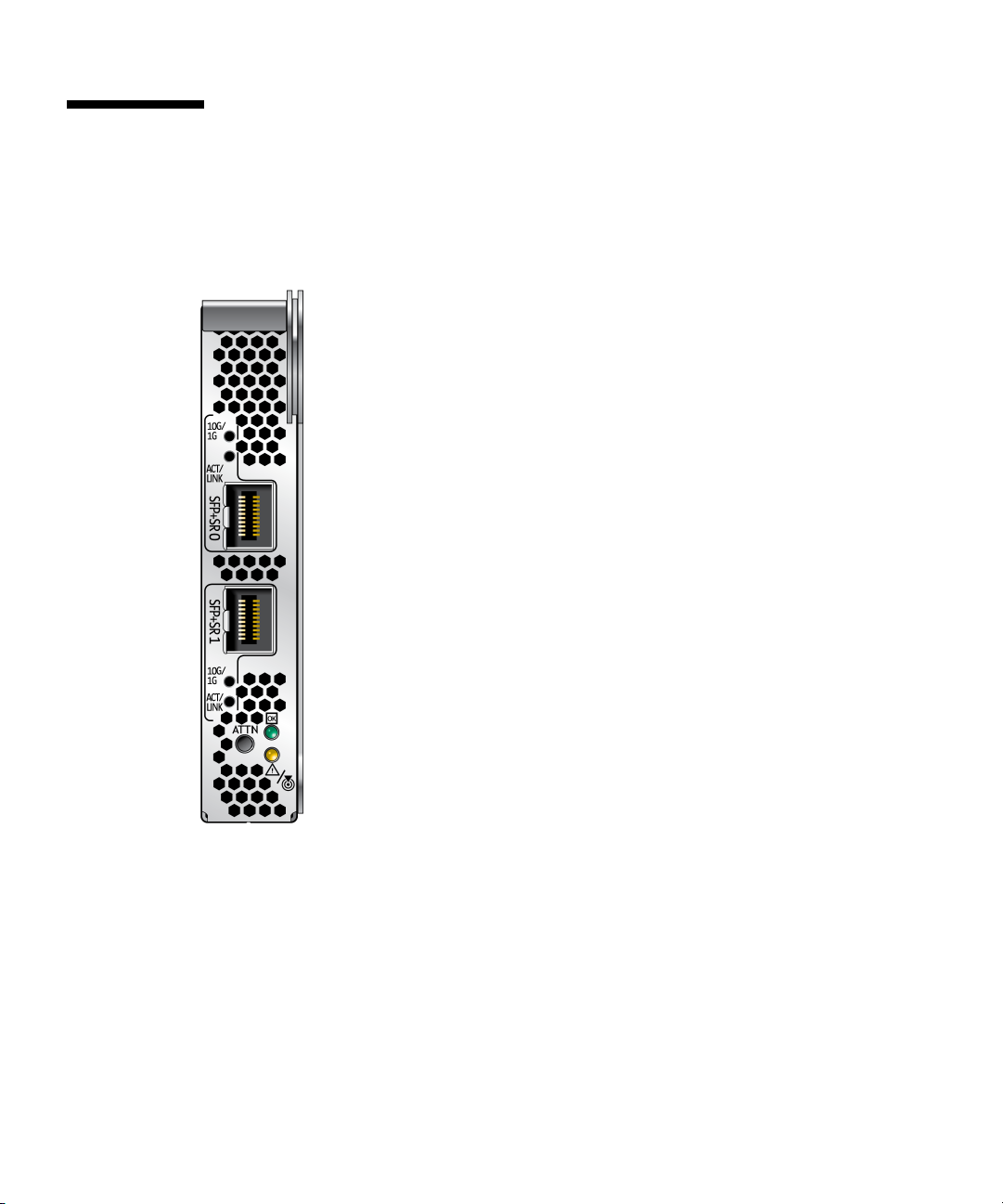
Connectors
FIGURE A-1 shows the connectors for the Sun 10GbE XFP SR PCI Express Card.
FIGURE A-1 Sun Dual 10GbE SFP+ PCIe ExpressModule Connectors (unpopulated)
46 Sun Dual 10GbE SFP+ PCIe ExpressModule User’s Guide • May 2010

Technical Features
TABLE A-1 Performance Specifications
Feature Specification
Data rate supported per port 10 Gigabit (Gb)
Bus type PCI Express 2.0
Bus width x8 lane PCI Express
Conforms to Ethernet Standard 802.3
Boot ROM 2 Mbit SPI Flash
Electromagnetic Interference (EMI) FCC Class A
Physical Characteristics
TABLE A-2 Physical Characteristics
Dimension Measurement
Length 6.62 in. (168.2 mm)
Width 4.25 in. (108 mm)
Power LED (green)
Attention LED (yellow)
Attention button (recessed)
Activity LED (each port) Green: 10 GbE link
Yellow: 1 GbE link
Appendix A Sun Dual 10GbE SFP+ PCIe ExpressModule Specifications 47

Power and Environmental Requirements
TABLE A-3 Card Power Requirements
Specification Measurement
Typical power consumption 14W (1.17A at 12V) dual port
Main host power supply 12 V ± 15%
Operating temperature 35 to 70 °C (95 to 158 °F) module inlet temperature
Storage temperature -40 to 70 °C (-40 to 158 °F)
Storage humidity 90% noncondensing relative humidity at 35 °C
Airflow 2 to 12 CFM
48 Sun Dual 10GbE SFP+ PCIe ExpressModule User’s Guide • May 2010

Index
B
bonding for multiple interfaces, 42
booting over the network
on Linux systems, 23
C
configuring bonding, 42
configuring the network host files, 23
configuring VLANs, 38
in Linux environments, 40
connectors, 46
D
driver parameters
for Solaris (e1000g), 26
tunable for Linux OS, 29
E
editing the network host files, 21
Ethernet adapter features, 2
H
hardware and software requirements, 5
hardware components, 1
I
ifconfig command, 39
installing the ExpressModule, 16
installing the ixgbe driver
on Linux platforms, 8
on Windows platforms, 11
J
Jumbo Frames, 30
L
link aggregation
in a Solaris environment, 32
overview, 31
N
networking interfaces, 25
P
patches
recommended patch clusters, 6
recommended security patches, 6
power requirements, 48
R
removing the ixgbe driver
from Linux platforms, 10
from Windows platforms, 12
S
setting ixgbe driver parameters, 25
shipping kit contents, 1
software and hardware requirements, 5
specifications, 45
Sun Dual 10GbE SFP+ PCIe ExpressModule
interfaces, 25
49

V
verifying the installation, 19
virtual device, 39
VLAN ID (VID), 38
VLAN naming format, 39
50 Sun Dual 10GbE SFP+ PCIe ExpressModule User’s Guide • May 2010
 Loading...