


Sun Datacenter InfiniBand Switch 36
Installation Guide for Firmware Version 2.1
Part No.: E36268-01
March 2013, Revision A

Copyright © 2013, Oracle and/orits affiliates.All rightsreserved.
This softwareand related documentation are provided under a license agreementcontaining restrictionson useand disclosure and are protectedby
intellectual propertylaws. Exceptas expressly permitted inyour licenseagreement or allowed by law, youmay notuse, copy, reproduce, translate,
broadcast, modify, license, transmit, distribute, exhibit, perform, publish, or display any part,in any form, orby anymeans. Reverseengineering,
disassembly, or decompilation of this software, unless requiredby law for interoperability, is prohibited.
The informationcontained hereinis subjectto changewithout noticeand isnot warrantedto beerror-free.If youfind anyerrors, please report them to us
in writing.
If thisis softwareor related software documentation that is deliveredto theU.S. Governmentor anyonelicensing iton behalfof theU.S. Government,the
following noticeis applicable:
U.S. GOVERNMENTEND USERS.Oracle programs,including anyoperating system,integrated software, any programs installed on the hardware,
and/or documentation,delivered toU.S. Governmentend usersare "commercial computer software" pursuantto theapplicable FederalAcquisition
Regulation andagency-specific supplementalregulations. Assuch, use,duplication, disclosure, modification, andadaptation of the programs, including
any operatingsystem, integratedsoftware, anyprograms installed on the hardware,and/or documentation,shall besubject tolicense termsand license
restrictions applicableto theprograms. No other rights are granted to the U.S. Government.
This softwareor hardware isdeveloped forgeneral use in a variety of informationmanagement applications.It isnot developedor intended for use inany
inherently dangerous applications, includingapplications whichmay create a risk of personal injury. Ifyou usethis software or hardware in dangerous
applications, thenyou shallbe responsibleto takeall appropriate fail-safe, backup,redundancy, andother measures to ensure its safe use. Oracle
Corporation andits affiliatesdisclaim anyliability forany damagescaused byuse ofthis software or hardware in dangerous applications.
Oracle andJava areregistered trademarks of Oracle and/or its affiliates.Other namesmay betrademarks oftheir respective owners.
Intel andIntel Xeonare trademarksor registered trademarks of Intel Corporation. All SPARCtrademarks are used underlicense andare trademarks or
registered trademarks of SPARCInternational, Inc.AMD, Opteron, theAMD logo,and theAMD Opteron logo are trademarksor registered trademarks of
Advanced MicroDevices. UNIXis aregistered trademark of The Open Group.
This software or hardware and documentation may provide access to or information on content, products, and services from third parties. Oracle
Corporation and its affiliates are not responsible for and expressly disclaim all warranties of any kind with respect to third-party content, products, and
services. Oracle Corporation and its affiliates will not be responsible for any loss, costs, or damages incurred due to your access to or use of third-party
content, products, or services.
Copyright ©2013, Oracleet/ou sesaffiliés. Tous droits réservés.
Ce logicielet ladocumentation quil’accompagne sontprotégés parles loissur lapropriété intellectuelle. Ils sont concédés sous licence et soumis à des
restrictions d’utilisationet dedivulgation. Saufdisposition devotre contrat de licence ou de la loi, vous ne pouvez pas copier, reproduire, traduire,
diffuser,modifier, breveter, transmettre,distribuer,exposer, exécuter, publier ou afficher le logiciel, même partiellement, sous quelque forme et par
quelque procédéque cesoit. Parailleurs, ilest interdit de procéder à toute ingénierie inverse du logiciel, de le désassembler ou de le décompiler, excepté à
des finsd’interopérabilité avecdes logicielstiers outel queprescrit par la loi.
Les informationsfournies dansce documentsont susceptiblesde modificationsans préavis.Par ailleurs,Oracle Corporationne garantitpas qu’elles
soient exemptesd’erreurs etvous invite,le caséchéant, àlui enfaire part par écrit.
Si celogiciel, oula documentationqui l’accompagne,est concédésous licenceau Gouvernementdes Etats-Unis,ou àtoute entitéqui délivrela licencede
ce logicielou l’utilisepour lecompte duGouvernement desEtats-Unis, lanotice suivantes’applique :
U.S. GOVERNMENTEND USERS.Oracle programs,including anyoperating system,integrated software, any programs installed on the hardware,
and/or documentation,delivered toU.S. Governmentend usersare "commercial computer software" pursuantto theapplicable FederalAcquisition
Regulation andagency-specific supplementalregulations. Assuch, use,duplication, disclosure, modification, andadaptation of the programs, including
any operatingsystem, integratedsoftware, anyprograms installed on the hardware,and/or documentation,shall besubject tolicense termsand license
restrictions applicableto theprograms. No other rights are granted to the U.S. Government.
Ce logicielou matériela étédéveloppé pourun usagegénéral dansle cadred’applications degestion desinformations. Celogiciel oumatériel n’estpas
conçu nin’est destinéà êtreutilisé dansdes applicationsà risque,notamment dansdes applicationspouvant causerdes dommagescorporels. Si vous
utilisez celogiciel oumatériel dansle cadred’applications dangereuses, il estde votre responsabilité de prendretoutes les mesures de secours, de
sauvegarde, deredondance et autres mesures nécessairesà sonutilisation dans des conditionsoptimales de sécurité. OracleCorporation et ses affiliés
déclinent touteresponsabilité quantaux dommagescausés parl’utilisation dece logicielou matérielpour cetype d’applications.
Oracle etJava sontdes marquesdéposées d’OracleCorporation et/oude sesaffiliés.Tout autrenom mentionnépeut correspondre à des marques
appartenant àd’autres propriétaires qu’Oracle.
Intel etIntel Xeonsont desmarques oudes marques déposées d’IntelCorporation. Toutes les marques SPARCsont utiliséessous licenceet sontdes
marques oudes marques déposées deSPARC International, Inc. AMD, Opteron, lelogo AMDet lelogo AMDOpteron sontdes marques ou des marques
déposées d’AdvancedMicro Devices.UNIX estune marque déposée d’TheOpen Group.
Ce logicielou matérielet ladocumentation quil’accompagne peuventfournir desinformations oudes liensdonnant accèsà descontenus, desproduits et
des servicesémanant detiers. OracleCorporation etses affiliésdéclinent touteresponsabilité ou garantie expresse quant aux contenus,produits ou
services émanantde tiers.En aucuncas, OracleCorporation etses affiliésne sauraientêtre tenus pour responsables des pertes subies, des coûts
occasionnés oudes dommagescausés parl’accès àdes contenus,produits ouservices tiers,ou àleur utilisation.

Contents
Using This Documentation vii
Understanding the Switch 1
Switch Overview 1
Physical Specifications 2
Environmental Requirements 2
Acoustic Noise Emissions 3
Electrical Specifications 3
NET MGT Connector and Pins 4
USB Management Connector and Pins 5
InfiniBand QSFP Connector and Pins 5
Understanding Cabling 9
Routing Service Cables 9
Power Cord Requirements 9
Management Cable Requirements 10
Understanding InfiniBand Cabling 11
InfiniBand Cable Cautions 12
InfiniBand Cable Guidelines 13
InfiniBand Cable Types 14
InfiniBand Cable Path Lengths 14
InfiniBand Cable Bundling 15
Floor and Underfloor Delivery of InfiniBand Cables 16
iii

Overhead Delivery of InfiniBand Cables 16
Preparing to Install the Switch 17
Installation Preparation 17
Suggested Tools for Installation 18
Antistatic Precautions for Installation 19
Installation Responsibilities 19
Installation Sequence 20
▼ Verify Shipping Carton Contents 21
▼ Assemble the Optical Fiber InfiniBand Cables 22
▼ Route the InfiniBand Cables 24
Installing the Switch 25
▼ Install the Switch in the Rack 25
Powering On the Switch 31
▼ Attach the Management Cables 31
▼ Attach the Power Cords 34
Accessing the Management Controller 36
▼ Access the Management Controller From the NET MGT Port 36
▼ Access the Management Controller From the USB Management
Port 38
▼ Verify the Switch Status 39
▼ Start the Subnet Manager 42
Connecting InfiniBand cables 44
▼ Attach the InfiniBand Cables 44
▼ Check Link Status 49
Verifying the InfiniBand Fabric 49
InfiniBand Node Description 50
▼ Discover the InfiniBand Fabric Topology 50
▼ Perform Diagnostics on the InfiniBand Fabric 51
iv Sun Datacenter InfiniBand Switch 36 Installation Guide for Firmware Version 2.1 • March 2013

Index 53
Contents v

vi Sun Datacenter InfiniBand Switch 36 Installation Guide for Firmware Version 2.1 • March 2013

Using This Documentation
This installation guide provides detailed procedures that describe the preparation
and installation of the Sun Datacenter InfiniBand Switch 36 from Oracle. This
document is written for technicians, system administrators, and users who have
advanced experience installing and administering InfiniBand fabric hardware.
■ “Product Notes” on page vii
■ “Related Documentation” on page viii
■ “Feedback” on page viii
■ “Access to Oracle Support” on page viii
Product Notes
For late-breaking information and known issues about this product, refer to the
product notes at:
http://docs.oracle.com/cd/E36265_01
vii

Related Documentation
Documentation Links
Sun Datacenter InfiniBand Switch 36 Firmware Version 2.1 http://docs.oracle.com/cd/E36265_01
Oracle Integrated Lights Out Manager (ILOM) 3.0 http://docs.oracle.com/cd/E19860-01
All Oracle products http://www.oracle.com/documentation
Feedback
Provide feedback on this documentation at:
http://www.oracle.com/goto/docfeedback
Access to Oracle Support
Oracle customers have access to electronic support through My Oracle Support. For
information, visit http://www.oracle.com/pls/topic/lookup?ctx=acc&id=
info or http://www.oracle.com/pls/topic/lookup?ctx=acc&id=trs visit
if you are hearing impaired.
viii Sun Datacenter InfiniBand Switch 36 Installation Guide for Firmware Version 2.1 • March 2013

Understanding the Switch
These topics describe the purpose and specifications of the switch, and the
connectors found on the switch chassis.
■ “Switch Overview” on page 1
■ “Physical Specifications” on page 2
■ “Environmental Requirements” on page 2
■ “Acoustic Noise Emissions” on page 3
■ “Electrical Specifications” on page 3
■ “NET MGT Connector and Pins” on page 4
■ “USB Management Connector and Pins” on page 5
■ “InfiniBand QSFP Connector and Pins” on page 5
Related Information
■ “Understanding Cabling” on page 9
■ “Preparing to Install the Switch” on page 17
■ “Installing the Switch” on page 25
Switch Overview
The Sun Datacenter InfiniBand Switch 36 provides InfiniBand fabric switching and
management capabilities. The switch utilizes the OFED InfiniBand software stack
through an internally configured management controller. The switch has 36 physical
InfiniBand QDR ports.
Monitoring the many aspects of the switch is simplified by a web-based Fabric
Monitor, allowing point and click polling and verification of settings, parameters,
and status.
1

Related Information
■ “Understanding Cabling” on page 9
■ “Preparing to Install the Switch” on page 17
■ “Installing the Switch” on page 25
Physical Specifications
This table lists the physical dimensions of the switch.
Dimension Measurements
Width 17.52 in. (445.0 mm)
Depth 24 in. (609.6 mm)
Height 1.75 in. (44.5 mm)
Weight 23.0 lbs (11.4 kg)
Related Information
■ “Verify Shipping Carton Contents” on page 21
■ “Install the Switch in the Rack” on page 25
Environmental Requirements
This table lists the switch operating environment parameters.
Parameter Operating
Ambient temperature 41˚F to 89.6˚F (5˚C to 32˚C)
Relative humidity 5% to 85% noncondensing, 80˚F (27˚C) maximum wet bulb
Elevation (Sun requirement) Maximum 9840 feet (3000 meters) at 104˚F (40˚C)
2 Sun Datacenter InfiniBand Switch 36 Installation Guide for Firmware Version 2.1 • March 2013

Acoustic Noise Emissions
This table lists the permitted noise emissions of the switch.
Parameter Operating Idling
Acoustic power LWAd (1B=10dB) 7.1 B 7.2 B
Acoustic pressure LpAm 58.9 dBA 59.0 dBA
Electrical Specifications
This table lists the electrical requirements of the switch.
Parameter AC Version Requirement
Voltage 100 VAC to 240 VAC single phase, 47 to 63 Hz
Current (per input) 5.4 A maximum per input at 100 VAC
Current (total) 5.6 A maximum total for all inputs at 100 VAC
Power 550 Watts (Total input power is approximately equally
divided among the operating power supplies)
Related Information
■ “Power Cord Requirements” on page 9
■ “Attach the Power Cords” on page 34
Understanding the Switch 3

NET MGT Connector and Pins
This table lists the pinout of the NET MGT connector.
Pin. Signal
1 TXD+
2 TXD-
3 RXD+
4 Not used
5 Not used
6 RXD-
7 Not used
8 Not used
Related Information
■ “Management Cable Requirements” on page 10
■ “Attach the Management Cables” on page 31
■ “Access the Management Controller From the NET MGT Port” on page 36
4 Sun Datacenter InfiniBand Switch 36 Installation Guide for Firmware Version 2.1 • March 2013

USB Management Connector and Pins
This table lists the pinout of the USB management connector.
Pin Signal
1 +5 VDC
2 - Data
3 + Data
4 GND
Related Information
■ “Management Cable Requirements” on page 10
■ “Attach the Management Cables” on page 31
■ “Access the Management Controller From the USB Management Port” on page 38
InfiniBand QSFP Connector and Pins
The QSFP connector is a single InfiniBand port connection.
Understanding the Switch 5

This table lists the pinout for the connector.
Pin Signal Pin Signal Pin Signal Pin Signal
1 GND 11 SCL 21 RX2n 31 Reserved
2 TX2n 12 SDA 22 RX2p 32 GND
3 TX2p 13 GND 23 GND 33 TX3p
4 GND 14 RX3p 24 RX4n 34 TX3n
5 TX4n 15 RX3n 25 RX4p 35 GND
6 TX4p 16 GND 26 GND 36 TX1p
7 GND 17 RX1p 27 ModPrsL 37 TX1n
8 ModSelL 18 RX1n 28 IntL 38 GND
9 LPMode_Reset 19 GND 29 VccTx
10 VccRx 20 GND 30 Vcc1
This table provides descriptions of the QSFP signals.
Signal Description
GND Ground for both signal and power return
2
SDA I
SCL I
ModSelL Module select on low - enables reception of I
ResetL Reset on low
LPMode Low power mode
ModPrsL Module presence on low - identifies existence of QSFP connector
C interface data
2
C interface clock
2
C commands
6 Sun Datacenter InfiniBand Switch 36 Installation Guide for Firmware Version 2.1 • March 2013

Signal Description
IntL Interrupt on low - enables fault indication
Related Information
■ “InfiniBand Cable Types” on page 14
■ “Connecting InfiniBand cables” on page 44
Understanding the Switch 7

8 Sun Datacenter InfiniBand Switch 36 Installation Guide for Firmware Version 2.1 • March 2013

Understanding Cabling
These topics provide information that helps you understand the cabling
requirements of the switch.
■ “Routing Service Cables” on page 9
■ “Understanding InfiniBand Cabling” on page 11
Related Information
■ “Understanding the Switch” on page 1
■ “Preparing to Install the Switch” on page 17
■ “Installing the Switch” on page 25
Routing Service Cables
These topics describe cable routing requirements:
■ “Power Cord Requirements” on page 9
■ “Management Cable Requirements” on page 10
Related Information
■ “Understanding InfiniBand Cabling” on page 11
Power Cord Requirements
The power supplies are in a N+N redundancy. Line power is provided from two
sources, A and B.
Your switch country kit should contain two power cords that are specific to your
country or application. This table describes the power cords available.
9

Cable Part Number Description
X311L (180-1097) North America/Asia, IEC 320 C13 to NEMA 5-15P - 15A/125V 2.5M Black, RoHS:Y
X312E (180-1982) China, IEC 320 C13 to GB 2099/GB 1002 - 10A/250V 2.0M, RoHS:Y
X312F (180-1999) Argentina, IEC 320 C13 to IRAM 2073 - 10A/250V 2.0M Black, RoHS:Y
X312G (180-1662) Korea, IEC 320 C13 to KSC 8305 - 15A/250V 2.0M Black, RoHS:Y
X312L (180-1993) Continental Europe, IEC 320 C13 to CEE 7/7 10A/250V 2.0M Black, RoHS:Y
X314L (180-1994) Swiss, IEC 320 C13 to SEV 1011 - 10A/250V 2.0M Black, RoHS:Y
X317L (180-1997) U.K., IEC 320 C13 to BS 1363 - 10A/250V 2.0M Black, RoHS:Y
X332A (180-2121) Taiwan, IEC 320 C13 to NEMA 5-15P - 10A/125V 2.5M Black, RoHS:Y
X383L (180-1995) Danish, IEC 320 C13 to Asfnit 107 - 10A/250V 2.0M Black, RoHS:Y
X384L (180-1996) Italian, IEC 320 C13 to CEI 23-16/VII - 10A/250V 2.0M Black, RoHS:Y
X386L (180-1998) Australian, IEC 320 C13 to AS 3112 - 10A/250V 2.0M Black, RoHS:Y
Caution – Install and route power cabling only in a manner that complies to federal,
state, and local electrical codes.
Related Information
■ “Electrical Specifications” on page 3
■ “Attach the Power Cords” on page 34
Management Cable Requirements
Management of the switch is done at the management console, which is either a
10/100 Ethernet connection at the NET ports or a USB-to-serial device attached to the
USB port.
Typically, the NET connection (network management) is the default means of
communicating with the management controller. The controller has a DHCP client in
operation and requires the Ethernet network to have a DHCP server. The DHCP
server must be configured with the MAC address of the management controller, so
the server can provide an IP address to the management controller upon boot. If a
DHCP server is not available, then the USB connection is used.
10 Sun Datacenter InfiniBand Switch 36 Installation Guide for Firmware Version 2.1 • March 2013

The advantage of the NET connection over the USB connection is that administration
of the switch can happen from anywhere on the network. There is no cable length
constraint for the network management route because of the re-amplification,
filtering, and processing that happens at each hub or switch within the Ethernet
network. No network management cable should be any longer than 100 meters.
The USB connection requires a USB-to-serial adapter. The adapter must be
configured to communicate with your serial device management console. The serial
device can be a serial terminal, a terminal server, or a serial connection running on a
system or laptop. Because of the nature of the serial signal, a serial management
cable cannot be used reliably if it is more than 10 meters long.
The USB-to-serial adapter is not included with your switch. You can purchase such
an adapter from computer and electronics stores.
Related Information
■ “NET MGT Connector and Pins” on page 4
■ “USB Management Connector and Pins” on page 5
■ “Attach the Management Cables” on page 31
Understanding InfiniBand Cabling
These topics describe InfiniBand cabling:
■ “InfiniBand Cable Cautions” on page 12
■ “InfiniBand Cable Guidelines” on page 13
■ “InfiniBand Cable Types” on page 14
■ “InfiniBand Cable Path Lengths” on page 14
■ “InfiniBand Cable Bundling” on page 15
■ “Floor and Underfloor Delivery of InfiniBand Cables” on page 16
■ “Overhead Delivery of InfiniBand Cables” on page 16
Related Information
■ “Routing Service Cables” on page 9
■ “Connecting InfiniBand cables” on page 44
Understanding Cabling 11

InfiniBand Cable Cautions
To prevent InfiniBand cable damage, you must follow these cautions:
Do not uncoil the cable, as a kink
might occur. Hold the coil closed
as you unroll the cable, pausing
to allow the cable to relax as it is
unrolled.
Do not step on the cable or
connectors. Plan cable paths away
from foot traffic or rolling loads.
Do not pull the cable out of the
shipping box, through any
opening, or around any corners.
Unroll the cable as you lay it
down and move it through turns.
Do not twist the cable to open a
kink. If it is not severe, open the
kink by unlooping the cable.
Do not straighten the cable to
correct a bend that is too tight.
Leave the cable bend as is.
Do not drop the cable or
connectors from any height.
Gently set the cable down, resting
the cable connectors on a stable
surface.
Do not drag the cable or its
connectors over any surface.
Carry the entire cable to and from
the points of connection.
Do not bend the cables to a radius
tighter than 85 mm (3.4 inches).
Ensure that cable turns are as
wide as possible.
Do not pack the cable to fit a tight
space. Use an alternative cable
route.
Do not hang the cable for a length
more than 2 meters (7 feet).
Minimize the hanging weight
with intermediate retention
points.
Do not cinch the cable with hard
fasteners or cable ties. Use soft
hook-and-loop fastener for
bundling and securing cables.
Do not force the cable connector
into the receptacle by pushing on
the cable. Apply connection or
disconnection forces at the
connector only.
Related Information
■ “InfiniBand Cable Guidelines” on page 13
■ “InfiniBand Cable Types” on page 14
■ “InfiniBand Cable Path Lengths” on page 14
■ “InfiniBand Cable Bundling” on page 15
12 Sun Datacenter InfiniBand Switch 36 Installation Guide for Firmware Version 2.1 • March 2013

■ “Floor and Underfloor Delivery of InfiniBand Cables” on page 16
■ “Overhead Delivery of InfiniBand Cables” on page 16
InfiniBand Cable Guidelines
Proper InfiniBand cable installation requires the following:
1. Plan the cable routes and cable length needs.
Identify problematic cable route bends, minimizing the length of continuous
vertical runs to no more than 2 meters (7 feet), and specify hardware to support
cable routing.
See “InfiniBand Cable Path Lengths” on page 14.
2. Carry the entire cable to the points of connection and unroll the cable from the
first connection point to the second
Keep the coil closed and pause to enable the cable to relax as it is unrolled and
moved through turns.
3. Ensure that cable route turns are larger than 85 mm (3.4 inches) radius for optical
cables and 127 mm (5 inches) radius for copper cables.
Find alternative routes for turns that are tighter.
4. Secure the cable to hard points and bundle it with soft, hook-and-loop fasteners.
See “InfiniBand Cable Bundling” on page 15.
5. Mediate the slack between securing points to maintain minimal cable tension and
proper support.
See “Floor and Underfloor Delivery of InfiniBand Cables” on page 16 and
“Overhead Delivery of InfiniBand Cables” on page 16.
6. Label the ends of cables to identify their routes.
7. Rest the cable connectors on a stable surface when they are not connected.
Related Information
■ “Power Cord Requirements” on page 9
■ “Management Cable Requirements” on page 10
■ “InfiniBand Cable Cautions” on page 12
■ “InfiniBand Cable Types” on page 14
■ “InfiniBand Cable Path Lengths” on page 14
■ “InfiniBand Cable Bundling” on page 15
Understanding Cabling 13

■ “Floor and Underfloor Delivery of InfiniBand Cables” on page 16
■ “Overhead Delivery of InfiniBand Cables” on page 16
InfiniBand Cable Types
This table lists the InfiniBand cables available for the switch, their length, and data
rate.
Cable Characteristics Lengths Data Rate
Pass-through, optical core, QSFP - QSFP 10 m QDR
Pass-through, copper core, QSFP - QSFP 1 m, 2 m, 3 m, 5 m QDR
Related Information
■ “InfiniBand QSFP Connector and Pins” on page 5
■ “InfiniBand Cable Cautions” on page 12
■ “InfiniBand Cable Guidelines” on page 13
■ “InfiniBand Cable Path Lengths” on page 14
■ “InfiniBand Cable Bundling” on page 15
■ “Floor and Underfloor Delivery of InfiniBand Cables” on page 16
■ “Overhead Delivery of InfiniBand Cables” on page 16
InfiniBand Cable Path Lengths
Cable paths should be as short as possible. After calculating the length of a cable
path, select the shortest cable to satisfy the length requirement. When specifying a
cable, consider the following:
■ Bends in the cable path increase the required length of the cable. Rarely does a
cable travel in a straight line from connector to connector. Bends in the cable path
are necessary, and each bend increases the total length.
■ Bundling increases the required length of the cables. Bundling causes one or more
cables to follow a common path. However, the bend radius is different in different
parts of the bundle. If the bundle is large and unorganized, and there are many
bends, one cable might experience only the inner radius of bends, while another
cable might experience the outer radius of bends. In this situation, the differences
of the required lengths of the cables is quite substantial.
14 Sun Datacenter InfiniBand Switch 36 Installation Guide for Firmware Version 2.1 • March 2013

■ If you are routing the InfiniBand cable under the floor, consider the height of the
raised floor when calculating cable path length.
Related Information
■ “InfiniBand Cable Cautions” on page 12
■ “InfiniBand Cable Guidelines” on page 13
■ “InfiniBand Cable Types” on page 14
■ “InfiniBand Cable Bundling” on page 15
■ “Floor and Underfloor Delivery of InfiniBand Cables” on page 16
■ “Overhead Delivery of InfiniBand Cables” on page 16
InfiniBand Cable Bundling
When bundling InfiniBand cables in groups, use hook and loop straps to keep cables
organized. If possible, use color-coordinated straps to help identify cables and their
routing. The InfiniBand 4X copper conductor cables are fairly thick and heavy for
their length. Consider the retention strength of the hook and loop straps when
supporting cables. Bundle as few cables as reasonably possible. If the InfiniBand
cables break free of their straps and fall free, the cables might break internally when
they strike the floor or are jerked from tension.
You can bundle the cables using many hook and loop straps. Do not bundle more
than 12 cables together. A fully configured switch has 36 InfiniBand cables, which is
at least three bundles.
Place the hook and loop straps as close together as reasonably possible. For example,
every 1 ft (0.3 m). If a cable breaks free from a strap, the cable cannot fall far before it
is retained by another strap.
Related Information
■ “Connecting InfiniBand cables” on page 44
■ “InfiniBand Cable Cautions” on page 12
■ “InfiniBand Cable Guidelines” on page 13
■ “InfiniBand Cable Types” on page 14
■ “InfiniBand Cable Path Lengths” on page 14
■ “Floor and Underfloor Delivery of InfiniBand Cables” on page 16
■ “Overhead Delivery of InfiniBand Cables” on page 16
Understanding Cabling 15

Floor and Underfloor Delivery of InfiniBand Cables
The switch accepts InfiniBand cables from floor or underfloor delivery. The cable
management hardware at the rear of the switch supports the weight of the InfiniBand
cables.
Floor and underfloor delivery limits the tension in the InfiniBand cable to the weight
of the cable for the rack height of the switch.
Related Information
■ “Connecting InfiniBand cables” on page 44
■ “InfiniBand Cable Cautions” on page 12
■ “InfiniBand Cable Guidelines” on page 13
■ “InfiniBand Cable Types” on page 14
■ “InfiniBand Cable Path Lengths” on page 14
■ “InfiniBand Cable Bundling” on page 15
■ “Overhead Delivery of InfiniBand Cables” on page 16
Overhead Delivery of InfiniBand Cables
For overhead delivery, it is suggested that cable shelves and lattices be used to
support the InfiniBand cables.
If the overhead delivery has a large drop height, consider using an intermediate
support for the InfiniBand cables. Use of the support can limit the tension in the
InfiniBand cable to the weight of the cable for the distance between the supports and
the switch.
Related Information
■ “Connecting InfiniBand cables” on page 44
■ “InfiniBand Cable Cautions” on page 12
■ “InfiniBand Cable Guidelines” on page 13
■ “InfiniBand Cable Types” on page 14
■ “InfiniBand Cable Path Lengths” on page 14
■ “InfiniBand Cable Bundling” on page 15
■ “Floor and Underfloor Delivery of InfiniBand Cables” on page 16
16 Sun Datacenter InfiniBand Switch 36 Installation Guide for Firmware Version 2.1 • March 2013

Preparing to Install the Switch
These topics provide you with information that you need to know to prepare you for
the installation process.
■ “Installation Preparation” on page 17
■ “Suggested Tools for Installation” on page 18
■ “Antistatic Precautions for Installation” on page 19
■ “Installation Responsibilities” on page 19
■ “Installation Sequence” on page 20
■ “Verify Shipping Carton Contents” on page 21
■ “Assemble the Optical Fiber InfiniBand Cables” on page 22
■ “Route the InfiniBand Cables” on page 24
Related Information
■ “Understanding the Switch” on page 1
■ “Understanding Cabling” on page 9
■ “Installing the Switch” on page 25
Installation Preparation
Before installing or servicing the switch, you must prepare the following:
■ The environment where the switch is to be installed must conform to the
requirements found in “Environmental Requirements” on page 2.
■ The rack to receive the switch must have proper power, management, and
InfiniBand fabric cabling brought to it.
■ The rack must have an available location for the switch.
■ There must be a clean, dry, stable work surface.
17

Related Information
■ “Suggested Tools for Installation” on page 18
■ “Antistatic Precautions for Installation” on page 19
■ “Installation Responsibilities” on page 19
■ “Installation Sequence” on page 20
■ “Verify Shipping Carton Contents” on page 21
■ “Assemble the Optical Fiber InfiniBand Cables” on page 22
■ “Route the InfiniBand Cables” on page 24
Suggested Tools for Installation
These tools are necessary or beneficial for installing the switch:
■ Antistatic mat
■ Antistatic wrist strap
■ No. 2 Phillips screwdriver
■ No. 1 Phillips screwdriver
■ Flashlight
■ Gloves
■ Magnifying glass
Related Information
■ “Installation Preparation” on page 17
■ “Antistatic Precautions for Installation” on page 19
■ “Installation Responsibilities” on page 19
■ “Installation Sequence” on page 20
■ “Verify Shipping Carton Contents” on page 21
■ “Assemble the Optical Fiber InfiniBand Cables” on page 22
■ “Route the InfiniBand Cables” on page 24
18 Sun Datacenter InfiniBand Switch 36 Installation Guide for Firmware Version 2.1 • March 2013

Antistatic Precautions for Installation
When installing the switch chassis, take care to follow antistatic precautions:
■ Use an antistatic mat as a work surface.
■ Wear an antistatic wrist strap that is attached to either the mat or a metal portion
of the switch chassis.
Related Information
■ “Installation Preparation” on page 17
■ “Suggested Tools for Installation” on page 18
■ “Installation Responsibilities” on page 19
■ “Installation Sequence” on page 20
■ “Verify Shipping Carton Contents” on page 21
■ “Assemble the Optical Fiber InfiniBand Cables” on page 22
■ “Route the InfiniBand Cables” on page 24
Installation Responsibilities
The personnel who install the switch must be fully capable of these tasks:
■ Rackmount a heavy object
■ Perform line voltage verification
■ Connect delicate cables in tight spaces
■ Configure network hosts and serial terminals
■ Perform software tasks of an administrative nature
■ Interpret screen output as it pertains to InfiniBand fabrics
Related Information
■ “Installation Preparation” on page 17
■ “Suggested Tools for Installation” on page 18
■ “Antistatic Precautions for Installation” on page 19
■ “Installation Sequence” on page 20
Preparing to Install the Switch 19

■ “Verify Shipping Carton Contents” on page 21
■ “Assemble the Optical Fiber InfiniBand Cables” on page 22
■ “Route the InfiniBand Cables” on page 24
Installation Sequence
The process of installing the switch has a specific sequence of tasks that must be
performed in order. This table describes the switch installation task sequence and
provides links to those procedures.
Step Links
1. “Verify Shipping Carton Contents” on page 21
2. “Assemble the Optical Fiber InfiniBand Cables” on page 22
3. “Route the InfiniBand Cables” on page 24
4. “Install the Switch in the Rack” on page 25
5. “Attach the Management Cables” on page 31
6. “Attach the Power Cords” on page 34
7. “Accessing the Management Controller” on page 36
8. “Verify the Switch Status” on page 39
9. “Start the Subnet Manager” on page 42
10. “Attach the InfiniBand Cables” on page 44
11. “Check Link Status” on page 49
12. “Discover the InfiniBand Fabric Topology” on page 50
13. “Perform Diagnostics on the InfiniBand Fabric” on page 51
Related Information
■ “Installation Preparation” on page 17
■ “Suggested Tools for Installation” on page 18
■ “Antistatic Precautions for Installation” on page 19
■ “Installation Responsibilities” on page 19
■ “Verify Shipping Carton Contents” on page 21
■ “Assemble the Optical Fiber InfiniBand Cables” on page 22
20 Sun Datacenter InfiniBand Switch 36 Installation Guide for Firmware Version 2.1 • March 2013
■ “Route the InfiniBand Cables” on page 24
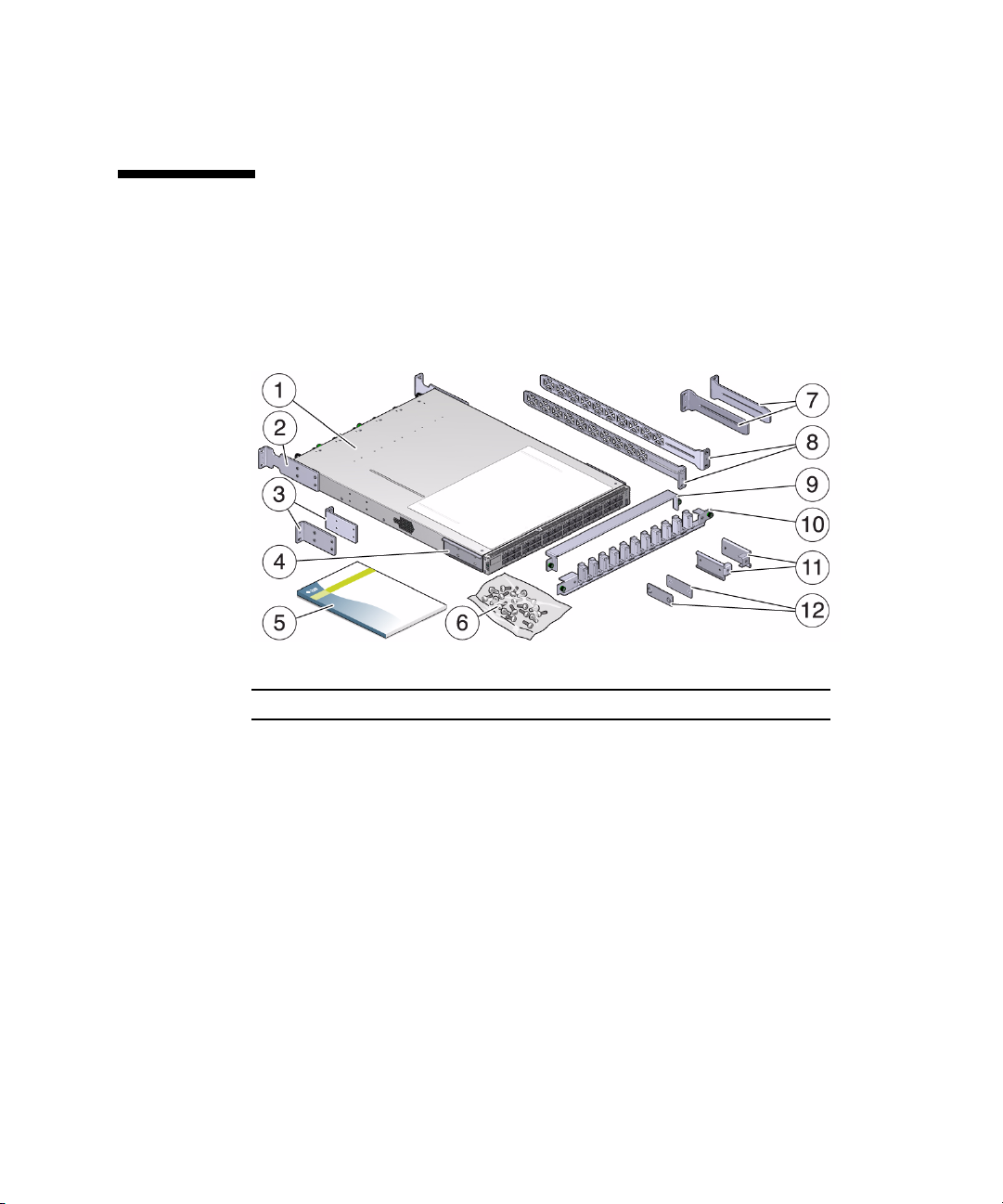
▼ Verify Shipping Carton Contents
1. Open the switch shipping carton and any additional cartons.
Power cords and InfiniBand cables are shipped separately.
2. Compare the contents to this figure.
Item Description
1 Switch
2 Front mounting brackets, long
3 Front mounting brackets, short
4 C-shaped brackets
5 Documentation
6 Hardware
7 Cable management extenders
8 Long side brackets
9 Cable management cover
10 Cable management assembly
11 Attachment brackets
12 Attachment plates
Preparing to Install the Switch 21

Item Description
Power cords and InfiniBand cables (not pictured)
3. After verifying the package contents, assemble the optical fiber InfiniBand
cables.
See “Assemble the Optical Fiber InfiniBand Cables” on page 22.
Related Information
■ “Installation Preparation” on page 17
■ “Suggested Tools for Installation” on page 18
■ “Antistatic Precautions for Installation” on page 19
■ “Installation Responsibilities” on page 19
■ “Installation Sequence” on page 20
■ “Assemble the Optical Fiber InfiniBand Cables” on page 22
■ “Route the InfiniBand Cables” on page 24
▼ Assemble the Optical Fiber InfiniBand
Cables
If the InfiniBand cables are unassembled, you must assemble the cables before
attaching them to the switch.
Note – The ends of the optical fiber cable and the receptacles of the transceivers
must be clean and optically clear before assembly. Do not remove the protective caps
from the optical fiber cable or the plugs from the transceivers until instructed to do
so.
1. Identify the prerequisite and subsequent installation tasks that you must
perform in conjunction with this procedure.
See “Installation Sequence” on page 20.
2. Remove the QSFP optical transceivers, SFP+ optical transceivers, and fiber optic
cables from their packaging.
3. Sort the components into groupings ready for assembly.
You will need two QSFP optical transceivers and a fiber optic cable.
22 Sun Datacenter InfiniBand Switch 36 Installation Guide for Firmware Version 2.1 • March 2013
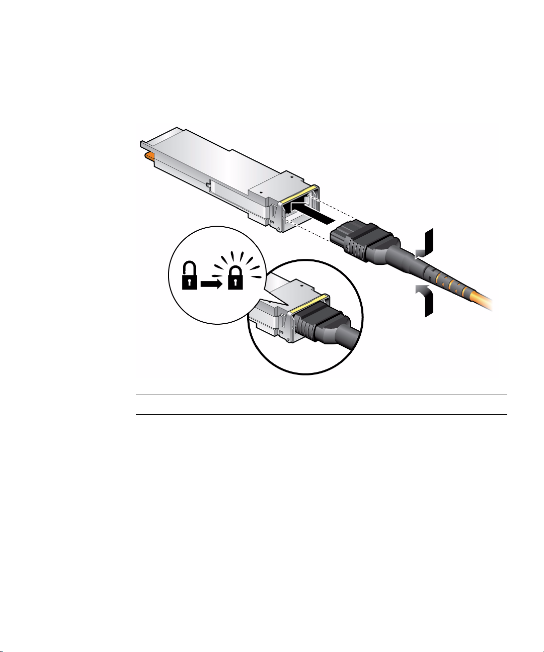
4. Remove the plug from the QSFP optical transceiver.
5. Remove the cap from the MTP connector of the fiber optic cable.
6. Holding the shaft of the MTP connector, insert the MTP connector into the
receptacle of the QSFP optical transceiver.
Note – The MTP connector and QSFP receptacle are keyed for proper fitting.
7. Push the connector into the transceiver until it clicks.
8. Repeat Step 4 to Step 7 for the other end of the cable.
9. Repeat from Step 3 for all InfiniBand cables to be assembled.
10. Route the InfiniBand cables.
See “Route the InfiniBand Cables” on page 24.
Related Information
■ “Understanding InfiniBand Cabling” on page 11
■ “Installation Preparation” on page 17
■ “Suggested Tools for Installation” on page 18
Preparing to Install the Switch 23

■ “Antistatic Precautions for Installation” on page 19
■ “Installation Responsibilities” on page 19
■ “Installation Sequence” on page 20
■ “Verify Shipping Carton Contents” on page 21
■ “Route the InfiniBand Cables” on page 24
▼ Route the InfiniBand Cables
1. Identify the prerequisite and subsequent installation tasks that you must
perform in conjunction with this procedure.
See “Installation Sequence” on page 20.
2. At the remote hosts, begin attaching the InfiniBand cables to the appropriate
connectors.
3. Route and bundle the InfiniBand cables following the cautions and guidelines
provided in “Understanding InfiniBand Cabling” on page 11.
4. Bring the cables to the location in the rack where the switch will install.
5. Install the switch into the rack.
See “Install the Switch in the Rack” on page 25.
Related Information
■ “InfiniBand Cable Guidelines” on page 13
■ “Installation Preparation” on page 17
■ “Suggested Tools for Installation” on page 18
■ “Antistatic Precautions for Installation” on page 19
■ “Installation Responsibilities” on page 19
■ “Installation Sequence” on page 20
■ “Verify Shipping Carton Contents” on page 21
■ “Assemble the Optical Fiber InfiniBand Cables” on page 22
24 Sun Datacenter InfiniBand Switch 36 Installation Guide for Firmware Version 2.1 • March 2013

Installing the Switch
These topics provide procedures that instruct you how to install the switch.
■ “Install the Switch in the Rack” on page 25
■ “Powering On the Switch” on page 31
■ “Connecting InfiniBand cables” on page 44
■ “Verifying the InfiniBand Fabric” on page 49
Related Information
■ “Understanding the Switch” on page 1
■ “Understanding Cabling” on page 9
■ “Preparing to Install the Switch” on page 17
▼ Install the Switch in the Rack
Caution – The airflow through the switch is in from the fans, through the chassis,
and out at the connector panel. The front of the switch chassis (fan end) intakes from
the cold aisle, and the rear of the switch chassis (connector end) exhausts to the hot
aisle. This flow direction requires you to install the switch in an orientation that is the
opposite of what you might assume.
1. Identify the prerequisite and subsequent installation tasks that you must
perform in conjunction with this procedure.
See “Installation Sequence” on page 20.
2. If installed, open the rack doors.
3. Assemble the cable management extenders.
25

a. Slide the attachment bracket over the extender, so that the tab on the bracket
is opposite the flange on the extender.
The open end of the tab is toward the flange. The flat end of the tab is toward
the rear of the extender.
b. Place the attachment plate on the flange side of the extender, opposite the
attachment bracket.
c. Use two screws to sandwich the attachment bracket and plate to the extender,
in the position farthest from the flange.
d. Using a No. 2 Phillips screwdriver, tighten the two screws.
e. Repeat from Step a for the other cable management extender.
4. Attach the cable management extenders and long rails to the rear of the rack.
a. Place the long rail to the mounting location on the post of the rack.
b. Butt the flange of the extender to the flange of the long rail.
26 Sun Datacenter InfiniBand Switch 36 Installation Guide for Firmware Version 2.1 • March 2013

c. Secure the assembly to the post with two captive nuts and two screws.
d. Repeat from Step a for the other cable management extender and long rail.
5. Attach the long front brackets (with cutouts) to the front of the switch with four
screws on each side.
The flange of the long front brackets point away from the switch.
Installing the Switch 27
6. Attach the C-shaped brackets to the switch with four screws on each side.
The edge of the C-shaped bracket is flush to the rear of the chassis.
7. Route the power cords through the rack with the female end at the front of the
rack where the switch will install.
Ensure that there is 24 inches (610 mm) of power cord slack at the front of the rack
to provide an adequate service loop when removing the switch from the rack.
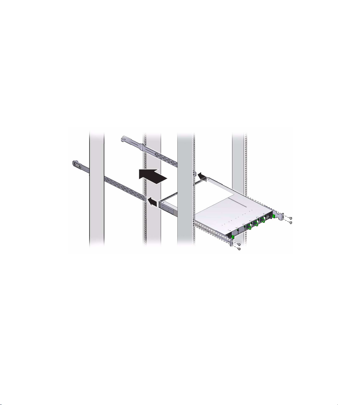
8. Carefully lift the switch and slide it into the rack, from the front rearward.
Ensure that the ends of the long rails slide into the C-shaped brackets at the rear of
the switch chassis and that the power cords lay into the cut-outs of the long front
mounting brackets.
9. Mount the front of the switch chassis to the front rack posts with two captive
nuts and two screws at each side.
Tighten the screws securely.
28 Sun Datacenter InfiniBand Switch 36 Installation Guide for Firmware Version 2.1 • March 2013

10. Install the cable management bracket to the tabs of the attachment brackets at
the rear of the switch, tightening the thumbscrews on each side of the cable
management bracket.
11. Install the cable management bracket cover.
Installing the Switch 29
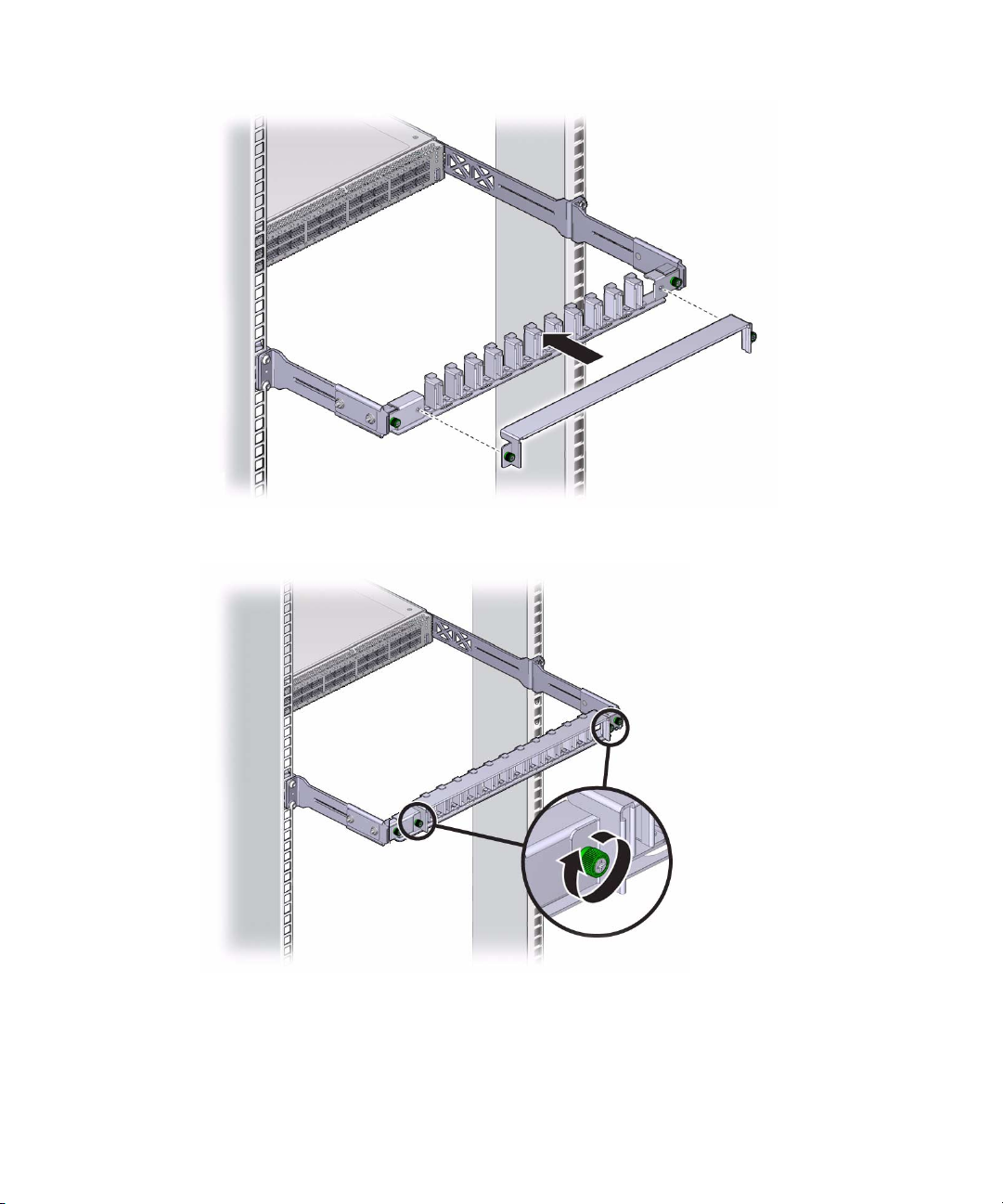
12. Tighten the thumbscrews on each side of the cover.
13. Attach the management cables.
See “Attach the Management Cables” on page 31.
30 Sun Datacenter InfiniBand Switch 36 Installation Guide for Firmware Version 2.1 • March 2013

Related Information
■ “Powering On the Switch” on page 31
■ “Connecting InfiniBand cables” on page 44
■ “Verifying the InfiniBand Fabric” on page 49
Powering On the Switch
After installing the components, enable powering on of the switch by performing
these tasks.
■ “Attach the Management Cables” on page 31
■ “Attach the Power Cords” on page 34
■ “Accessing the Management Controller” on page 36
■ “Verify the Switch Status” on page 39
■ “Start the Subnet Manager” on page 42
Related Information
■ “Electrical Specifications” on page 3
■ “Routing Service Cables” on page 9
■ “Install the Switch in the Rack” on page 25
■ “Connecting InfiniBand cables” on page 44
■ “Verifying the InfiniBand Fabric” on page 49
▼ Attach the Management Cables
The switch has two connectors for network or serial communication with the
management controller.
The network management connector, labeled NET, is a 100/1000 BASE-T Ethernet
interface. This connector is preferred because it permits remote management of the
switch over the Ethernet network.
The USB management connector, labeled with the USB symbol, is the second choice
for communication with the management controller in the switch. The management
console can be a serial terminal, a system running a TIP connection, or other serial
Installing the Switch 31

device that communicates with the management controller through a USB-to-serial
adapter. The serial parameters for communication with the USB-to-serial adapter is
typically 115600, 8, N, 1.
1. Identify the prerequisite and subsequent installation tasks that you must
perform in conjunction with this procedure.
See “Installation Sequence” on page 20.
2. Connect an Ethernet cable between the switch NET0 port and the network that
is configured with a DHCP server.
Connections to the management controller are made through DHCP.
3. Configure your DHCP server with the MAC address of the management
controller and to provide a host name and IP address to the switch.
The MAC address is printed on the customer information (yellow) sheet on the
outside of the switch shipping carton and on the pull-out tab on the left side front
of the switch chassis, adjacent to power supply 0.
Note – If a DHCP server is not available, the management controller has a default
static IP address of 169.254.0.36 with a subnet mask of 255.255.0.0. Alternatively, you
can connect a USB-to-serial adapter cable between the switch’s USB port and a
terminal device. This connection provides alternative communication with the
management controller. The terminal device must be configured for 115200 baud, 8
bit, no parity, 1 stop bit.
32 Sun Datacenter InfiniBand Switch 36 Installation Guide for Firmware Version 2.1 • March 2013

4. (Optional) Connect the serial management cables from the management console
to the USB-to-serial adapter and from the adapter to the connector labeled with
the USB symbol.
5. Route the management cables so that they do not interfere with other cables,
with servicing the switch, or with other systems.
6. Prepare the management console for communication with the management
controller.
7. Power on the switch.
See “Attach the Power Cords” on page 34.
Related Information
■ “NET MGT Connector and Pins” on page 4
■ “USB Management Connector and Pins” on page 5
■ “Management Cable Requirements” on page 10
■ “Attach the Power Cords” on page 34
■ “Accessing the Management Controller” on page 36
■ “Verify the Switch Status” on page 39
■ “Start the Subnet Manager” on page 42
■ “Attach the InfiniBand Cables” on page 44
Installing the Switch 33
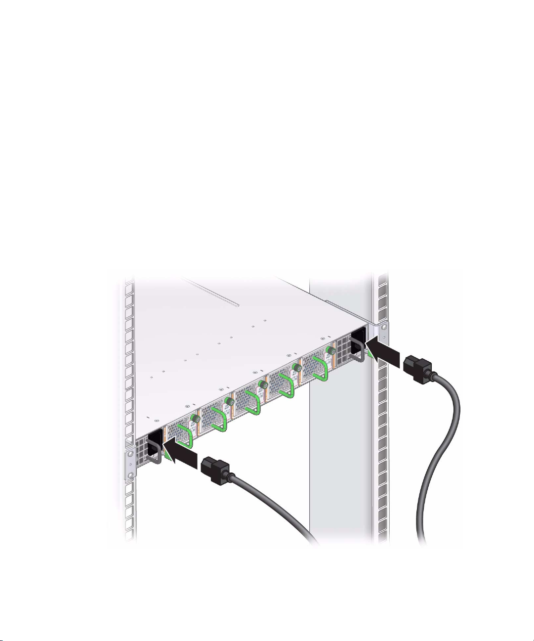
▼ Attach the Power Cords
The power cords for the switch ship separately and are specific to the country of
installation. See “Power Cord Requirements” on page 9. The facility power
receptacles for the power cords should be located such that the power cords are
routed out of the way, either to the sides of the rack or under the floor.
When live power is delivered to the receptacles at the rear of the chassis, standby and
main power is made available by the power supplies. When standby power is
distributed to the chassis, the management controller is powered on. The main power
is supplied for the switch chip and fans.
1. Identify the prerequisite and subsequent installation tasks that you must
perform in conjunction with this procedure.
See “Installation Sequence” on page 20.
2. Ensure that the circuit breakers for the facility power are switched off.
3. Plug the power cords into the receptacles at the front of the switch chassis.
4. Route the end of each power cord to its respective facility power receptacle.
Use cable ties or hook and loop fastener straps to bundle and secure the cord.
34 Sun Datacenter InfiniBand Switch 36 Installation Guide for Firmware Version 2.1 • March 2013

5. Plug each power cord into the receptacle.
Note – To provide redundancy, connect each power cord to a separate power source.
The switch can operate with only one power source, but there is no redundancy in
that case.
6. Energize the circuit breakers so that the power receptacles are live.
7. Verify that the status LEDs for each power supply indicate normal operation.
The AC LED on each power supply lights green. A moment later, the OK LED
lights green. The Attention LED should be unlit. Refer to Switch Service , checking
power supply status LEDs.
■ If the AC LED does not light, there is something wrong with supplied power.
■ If the OK LED does not light, there is something wrong with the power supply.
■ If the Attention LED on a power supply lights, there is a fault in the power
supply.
■ If the Attention LED on a fan lights, there is a fault with that fan.
Note – At this time, power is being supplied to the management controller. The
controller is effectively on and booting up. You might see the boot sequence on the
management console.
8. Verify that the fans spin up.
You should feel air going into the fans, and the fan Attention LEDs should be
unlit. Refer to Switch Service, checking fan status LEDs.
9. Verify that the chassis status OK LED lights.
Refer to Switch Service, checking chassis status LEDs.
10. Access the management controller.
See “Accessing the Management Controller” on page 36.
Related Information
■ “Power Cord Requirements” on page 9
■ “Electrical Specifications” on page 3
■ “Attach the Management Cables” on page 31
■ “Accessing the Management Controller” on page 36
■ “Verify the Switch Status” on page 39
■ “Start the Subnet Manager” on page 42
■ “Attach the InfiniBand Cables” on page 44
Installing the Switch 35

Accessing the Management Controller
With power applied, you can now access the management controller.
■ “Access the Management Controller From the NET MGT Port” on page 36
■ “Access the Management Controller From the USB Management Port” on page 38
Related Information
■ “NET MGT Connector and Pins” on page 4
■ “USB Management Connector and Pins” on page 5
■ “Management Cable Requirements” on page 10
■ “Attach the Management Cables” on page 31
■ “Attach the Power Cords” on page 34
■ “Verify the Switch Status” on page 39
■ “Start the Subnet Manager” on page 42
▼ Access the Management Controller From the NET MGT
Port
Note – The administrator of the switch has the username of ilom-admin.
1. Identify the prerequisite and subsequent installation tasks that you must
perform in conjunction with this procedure.
See “Installation Sequence” on page 20.
2. If you have not already done so, configure your DHCP server.
Use the MAC address of the management controller to provide a host name and IP
address for the switch.
See “Attach the Management Cables” on page 31.
36 Sun Datacenter InfiniBand Switch 36 Installation Guide for Firmware Version 2.1 • March 2013

3. Open a SSH session and connect to the management controller by specifying
the controller’s host name as configured with the DHCP server.
For example:
% ssh -l ilom-admin switch_name
ilom-admin@switch_name’s password: password
Last login: Wed Dec 12 03:48:06 2012 from 10.195.1.11
###############################################
# This user never changed the default password.
# Please change password immediately!
###############################################
Oracle(R) Integrated Lights Out Manager
Version ILOM 3.0 r47111
Copyright (c) 2012, Oracle and/or its affiliates. All rights reserved.
->
where switch_name is the host name of the management controller. Initially, the
password is ilom-admin.
Note – You can change the password at a later time. Refer to Switch Remote
Management, changing the user password, for instructions on how to change the
ilom-admin password.
If you do not see this output or prompt, there is a problem with the DHCP
configuration, network management communication, or the management
controller. Refer to Switch Service, network management troubleshooting
guidelines.
4. Enter the restricted shell.
-> show /SYS/Fabric_Mgmt
NOTE: show on Fabric_Mgmt will launch a restricted Linux shell.
User can execute switch diagnosis, SM Configuration and IB
monitoring commands in the shell. To view the list of commands,
use "help" at rsh prompt.
Use exit command at rsh prompt to revert back to
ILOM shell.
FabMan@switch_name->
5. Verify the switch status.
See “Verify the Switch Status” on page 39.
Installing the Switch 37

Related Information
■ “NET MGT Connector and Pins” on page 4
■ “Management Cable Requirements” on page 10
■ “Access the Management Controller From the USB Management Port” on page 38
▼ Access the Management Controller From the USB
Management Port
1. Identify the prerequisite and subsequent installation tasks that you must
perform in conjunction with this procedure.
See “Installation Sequence” on page 20.
2. If you have not already done so, connect a USB-to-serial adapter to the USB port
of the switch.
3. Connect a serial terminal, terminal server, or workstation with a TIP connection
to the USB-to-serial adapter.
Configure the terminal or terminal emulator with these settings:
■ 115200 baud
■ 8 bits
■ No parity
■ 1 Stop bit
■ No handshaking
4. Press the Return or Enter key on the serial device several times to synchronize
the connection.
You might see text similar to this:
...
CentOS release 5.2 (Final)
Kernel 2.6.27.13-nm2 on an i686
switch_name login:
where switch_name is the host name of the management controller. Even if you do
not see the text, go to Step 5.
38 Sun Datacenter InfiniBand Switch 36 Installation Guide for Firmware Version 2.1 • March 2013

5. Type ilom-admin for the login name followed by the password of
ilom-admin.
switch_name login: ilom-admin
Password: ilom-admin
->
The -> prompt is displayed.
Note – You can change the password at a later time. Refer to Switch Administration,
changing the administrator password.
If you do not see this output or prompt, there is a problem with the serial
configuration, the USB-to-serial adapter, or the management controller.
6. Enter the restricted shell.
-> show /SYS/Fabric_Mgmt
NOTE: show on Fabric_Mgmt will launch a restricted Linux shell.
User can execute switch diagnosis, SM Configuration and IB
monitoring commands in the shell. To view the list of commands,
use "help" at rsh prompt.
Use exit command at rsh prompt to revert back to
ILOM shell.
FabMan@switch_name->
7. Verify the switch status.
See “Verify the Switch Status” on page 39.
Related Information
■ “USB Management Connector and Pins” on page 5
■ “Management Cable Requirements” on page 10
■ “Access the Management Controller From the NET MGT Port” on page 36
▼ Verify the Switch Status
You can use these commands on the management controller to check the status of the
switch.
Installing the Switch 39

1. Identify the prerequisite and subsequent installation tasks that you must
perform in conjunction with this procedure.
See “Installation Sequence” on page 20.
2. Check the overall health of the switch:
FabMan@switch_name-> showunhealthy
OK - No unhealthy sensors
FabMan@switch_name->
An unfavorable output from the showunhealthy command means a hardware
fault with that particular component.
3. Check the status of the power supplies:
FabMan@switch_name-> checkpower
PSU 0 present OK
PSU 1 present OK
All PSUs OK
FabMan@switch_name->
A power supply output that is not OK from the checkpower command means that
there is a problem with that power supply. Refer to Switch Service, checking power
supply status LEDs, for assistance.
4. Check the status of the fans:
FabMan@switch_name->getfanspeed
Fan 0 not present
Fan 1 running at rpm 12099
Fan 2 running at rpm 11772
Fan 3 running at rpm 11772
Fan 4 not present
FabMan@switch_name->
■ A stopped or low speed in the output of the getfanspeed command means
there is a problem with that particular fan.
■ If not present is in the output of the getfanspeed command, yet a fan is
installed at that particular slot, there is a problem with that fan.
For either condition, check the fan. Refer to Switch Service, servicing fans.
40 Sun Datacenter InfiniBand Switch 36 Installation Guide for Firmware Version 2.1 • March 2013

5. Check the status of the switch chip:
FabMan@switch_name->checkboot
Switch OK
All Internal ibdevices OK
FabMan@switch_name->
If in the output of the checkboot command a component is not OK, there is a
problem with that component. Try resetting the component. Refer to Switch
Administration, resetting the switch chip.
6. Alternatively, you can use the env_test command to perform the preceding
checks and more:
FabMan@switch_name->env_test
Environment test started:
Starting Environment Daemon test:
Environment daemon running
Environment Daemon test returned OK
Starting Voltage test:
Voltage ECB OK
Measured 3.3V Main = 3.28 V
Measured 3.3V Standby = 3.37 V
Measured 12V = 12.06 V
Measured 5V = 5.03 V
Measured VBAT = 3.25 V
Measured 2.5V = 2.49 V
Measured 1.8V = 1.78 V
Measured I4 1.2V = 1.22 V
Voltage test returned OK
Starting PSU test:
PSU 0 present
PSU 1 present
PSU test returned OK
Starting Temperature test:
Back temperature 28
Front temperature 28
SP temperature 42
Switch temperature 32, maxtemperature 32
Temperature test returned OK
Starting FAN test:
Fan 0 not present
Fan 1 running at rpm 11881
Fan 2 running at rpm 11663
Fan 3 running at rpm 11881
Fan 4 not present
FAN test returned OK
Starting Connector test:
Installing the Switch 41

Connector test returned OK
Starting Onboard ibdevice test:
Switch OK
All Internal ibdevices OK
Onboard ibdevice test returned OK
Starting SSD test:
SSD test returned OK
Environment test PASSED
FabMan@switch_name->
Note – If in the output of the env_test command a voltage deviates more than 10%
from the provided specification, there is a problem with the respective component.
7. Once the switch has an operational status, you can start the Subnet Manager.
See “Start the Subnet Manager” on page 42.
Related Information
■ Switch Reference, showunhealthy command
■ Switch Reference, getfanspeed command
■ Switch Reference, checkboot command
■ Switch Reference, env_test command
■ “Attach the Management Cables” on page 31
■ “Attach the Power Cords” on page 34
■ “Accessing the Management Controller” on page 36
■ “Start the Subnet Manager” on page 42
▼ Start the Subnet Manager
Note – If you do not need either a primary or secondary Subnet Manager running
on the switch, you can skip this procedure and attach the InfiniBand cables. See
“Attach the InfiniBand Cables” on page 44.
Your InfiniBand fabric requires only one primary (or master) Subnet Manager, and it
has the highest priority. If any other Subnet Managers exist, they are secondary (or
standby) Subnet Managers, and must have a lower priority. You must determine
which switch, gateway, or InfiniBand device hosts the primary Subnet Manager, and
if there are secondary Subnet Managers. If you have only one switch in your
InfiniBand fabric, and there are no Subnet Managers other than the one within the
management controller, you do not need to set the Subnet Manager priority.
42 Sun Datacenter InfiniBand Switch 36 Installation Guide for Firmware Version 2.1 • March 2013

1. Identify the prerequisite and subsequent installation tasks that you must
perform in conjunction with this procedure.
See “Installation Sequence” on page 20.
2. Enable the Subnet Manager:
FabMan@switch_name-> enablesm
Starting IB Subnet Manager. [ OK ]
Starting partitiond daemon. [ OK ]
FabMan@switch_name->
3. (Optional) Configure the priority of the Subnet Manager within the
management controller.
a. Set the priority of the Subnet Manager:
FabMan@switch_name-> setsmpriority priority
where priority is 0 (lowest) to 13 (highest). For example, to set the Subnet
Manager to priority 13:
FabMan@switch_name-> setsmpriority 13
Current SM settings:
smpriority 13
controlled_handover FALSE
subnet_prefix 0xfe80000000000000
M_Key None
Routing engine FatTree
FabMan@switch_name->
b. Restart the Subnet Manager:
FabMan@switch_name-> disablesm
Stopping partitiond daemon. [ OK ]
Stopping IB Subnet Manager.. [ OK ]
FabMan@switch_name-> enablesm
Starting IB Subnet Manager. [ OK ]
Starting partitiond daemon. [ OK ]
FabMan@switch_name->
4. Attach the InfiniBand cables.
See “Attach the InfiniBand Cables” on page 44.
Related Information
■ Switch Reference, setsmpriority command
Installing the Switch 43

■ Switch Reference, enablesm command
■ “Attach the Management Cables” on page 31
■ “Attach the Power Cords” on page 34
■ “Accessing the Management Controller” on page 36
■ “Verify the Switch Status” on page 39
Connecting InfiniBand cables
After verifying the switch operational status, you can begin attaching the InfiniBand
cables.
■ “Attach the InfiniBand Cables” on page 44
■ “Check Link Status” on page 49
Related Information
■ “Understanding InfiniBand Cabling” on page 11
■ “Install the Switch in the Rack” on page 25
■ “Powering On the Switch” on page 31
■ “Verifying the InfiniBand Fabric” on page 49
▼ Attach the InfiniBand Cables
Caution – InfiniBand cables must never turn tighter than a 5-inch (127 mm) radius.
A tighter radius damages the wires and fibers inside the cable.
Note – When you install the InfiniBand cables, connect cables to the lower
connectors first, then connect cables to the upper connectors.
1. Identify the prerequisite and subsequent installation tasks that you must
perform in conjunction with this procedure.
See “Installation Sequence” on page 20.
2. Loosen the two captive thumbscrews that secure the cover to the cable
management bracket.
44 Sun Datacenter InfiniBand Switch 36 Installation Guide for Firmware Version 2.1 • March 2013

3. Lift the cover off.
Installing the Switch 45
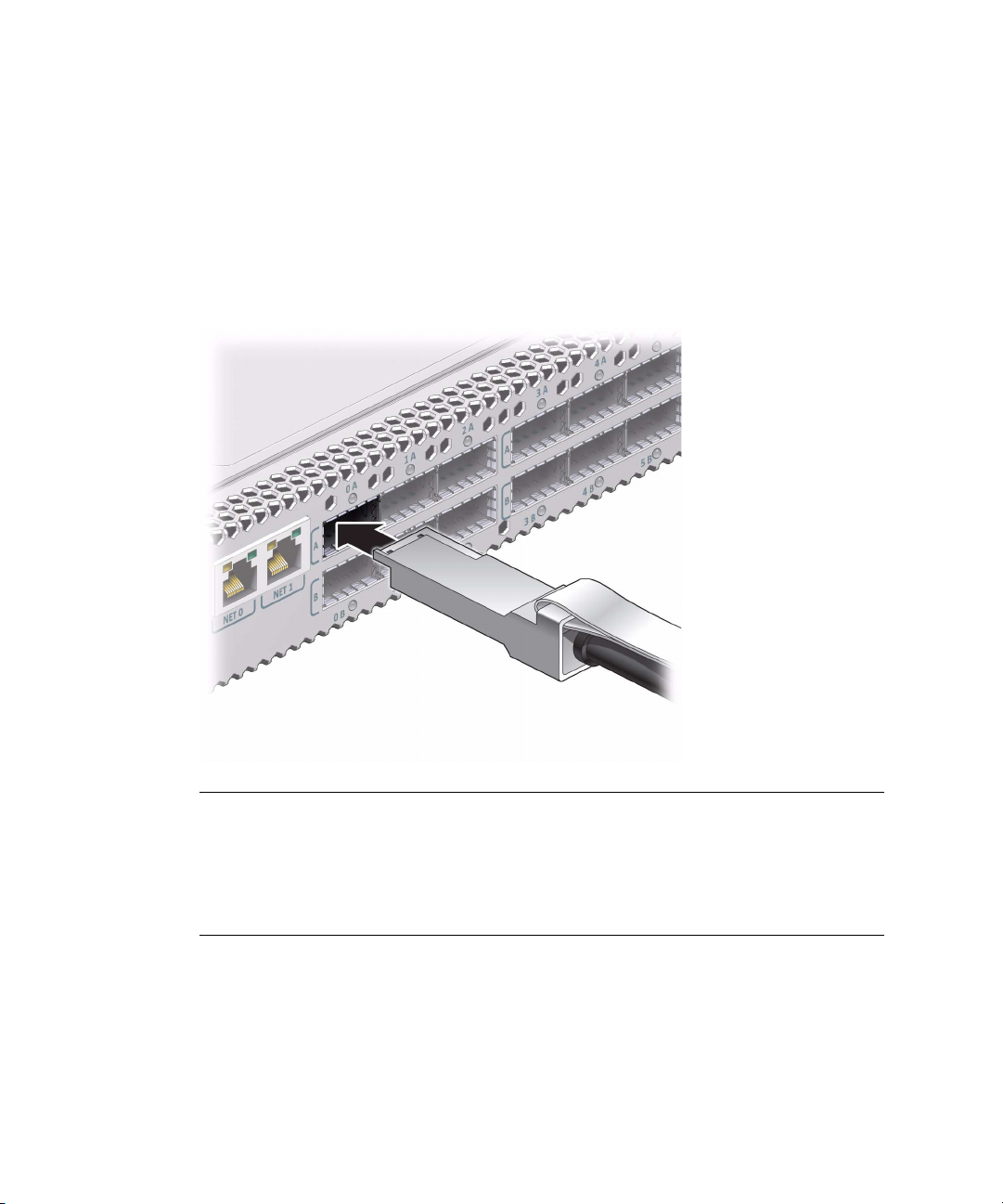
4. Remove the protective cap from the connector or transceiver and visually
inspect the cable connector.
The shell should not be bent and should be parallel to the inner boards. If the
connector is bent or damaged, use a different cable.
5. Ensure that the retraction strap is folded back against the cable.
6. Orient the cable connector to the QSFP receptacle squarely and horizontally.
Ensure that the L groove is up for the top row of receptacles, or that the L groove
is down for the bottom row of receptacles.
Note – On some QSFP cable connectors, there is a retraction strap. Both the
retraction strap and L groove indicate the reference surface for the connector. When
installing QSFP cables in the top row of receptacles (0A, 1A, 2A, and so on), ensure
that the L groove and retraction strap are up. When installing QSFP cables in the
bottom row of receptacles (0B, 1B, 2B, and so on) ensure that the L groove and
retraction strap are down. Refer to Switch Service, identifying the InfiniBand cable.
7. Slowly move the connector in.
As you slide the connector in, the shell should be in the center of the QSFP
receptacle.
46 Sun Datacenter InfiniBand Switch 36 Installation Guide for Firmware Version 2.1 • March 2013

■ If the connector stops or binds after about 1/4 in. (5 mm) travel, back out and
repeat from Step 6.
■ If the connector stops or binds with about 1/8 in. (2 mm) still to go, back out
and repeat Step 7.
8. Continue to push the connector in until you feel a detent.
9. Place the cable into the open slot on the cable management bracket.
10. Repeat Step 4 through Step 9 for all cables to be installed.
11. Replace the cover for the cable management bracket and tighten the
thumbscrews.
Installing the Switch 47

12. Route the InfiniBand cables so that they do not interfere with other cables, or
with servicing the switch or other systems.
Use hook and loop fastener straps to bundle and secure the cables.
Note – Do not use cable zip ties to bundle or secure the cables, because the ties
damage the fibers inside the cables.
13. Check that the Link LEDs for cabled links are lit green.
If the Link LED is unlit, the link is down. If the Link LED flashes, there are symbol
errors. Refer to Switch Service, checking the link status LEDs.
14. If possible, close the rack doors to maintain EMI compliance.
15. Check the link status.
See “Check Link Status” on page 49.
Related Information
■ “Understanding InfiniBand Cabling” on page 11
■ “Attach the Management Cables” on page 31
■ “Attach the Power Cords” on page 34
■ “Check Link Status” on page 49
48 Sun Datacenter InfiniBand Switch 36 Installation Guide for Firmware Version 2.1 • March 2013

▼ Check Link Status
1. Identify the prerequisite and subsequent installation tasks that you must
perform in conjunction with this procedure.
See “Installation Sequence” on page 20.
2. On the management controller, determine the state of the links:
FabMan@switch_name-> listlinkup link peer
■ If the link for a connector is reported as Not present, there is no cable
attached, or the link at either end of the cable is down.
■ If a port is down, use the enableswitchport command to bring the port up.
Refer to Switch Administration, enabling a switch chip port.
3. Verify the InfiniBand fabric.
See “Discover the InfiniBand Fabric Topology” on page 50.
Related Information
■ Switch Reference, listlinkup command
■ Switch Reference, enableswitchport command
■ “Verify the Switch Status” on page 39
■ “InfiniBand Cable Cautions” on page 12
■ “InfiniBand Cable Guidelines” on page 13
■ “Attach the InfiniBand Cables” on page 44
Verifying the InfiniBand Fabric
Use the ibnetdiscover and ibdiagnet commands to initially determine the
operational status of your Sun Datacenter InfiniBand Switch 36 from Oracle in the
InfiniBand fabric.
■ “InfiniBand Node Description” on page 50
■ “Discover the InfiniBand Fabric Topology” on page 50
■ “Perform Diagnostics on the InfiniBand Fabric” on page 51
Related Information
■ “Install the Switch in the Rack” on page 25
Installing the Switch 49

■ “Powering On the Switch” on page 31
■ “Connecting InfiniBand cables” on page 44
InfiniBand Node Description
In the output of some hardware and InfiniBand commands, the switch is identified
by its node description. The node description is of this format:
SUN IB QDR 36p switch hostname
where hostname is the host name of the management controller. An example node
description might be:
SUN IB QDR 36p switch mnm34-97
Related Information
■ “Discover the InfiniBand Fabric Topology” on page 50
■ “Perform Diagnostics on the InfiniBand Fabric” on page 51
▼ Discover the InfiniBand Fabric Topology
The ibnetdiscover command enables you to see the InfiniBand fabric topology.
1. Identify the prerequisite and subsequent installation tasks that you must
perform in conjunction with this procedure.
See “Installation Sequence” on page 20.
2. On the management controller, type:
FabMan@switch_name->ibnetdiscover
#
# Topology file: generated on Thu Dec 13 03:41:36 2012
#
# Max of 1 hops discovered
# Initiated from node 0021283a8389a0a0 port 0021283a8389a0a0
vendid=0x2c9
devid=0xbd36
sysimgguid=0x21283a8389a0a3
switchguid=0x21283a8389a0a0(21283a8389a0a0)
Switch 36 "S-0021283a8389a0a0" # "Sun DCS 36 QDR switch localhost" enhanced port
0 lid 15 lmc 0
[23] "H-0003ba000100e388"[2](3ba000100e38a) # "mnm33-43 HCA-1" lid 14 4xQDR
50 Sun Datacenter InfiniBand Switch 36 Installation Guide for Firmware Version 2.1 • March 2013

vendid=0x2c9
devid=0x673c
sysimgguid=0x3ba000100e38b
caguid=0x3ba000100e388
Ca 2 "H-0003ba000100e388" # "mnm33-43 HCA-1"
[2](3ba000100e38a) "S-0021283a8389a0a0"[23] # lid 14 lmc 0 "Sun DCS 36 QDR
switch localhost" lid 15 4xQDR
FabMan@switch_name->
Note – The output for your InfiniBand fabric will differ from that in the example.
3. Perform InfiniBand fabric diagnostics.
See “Perform Diagnostics on the InfiniBand Fabric” on page 51.
Related Information
■ Switch Reference, ibnetdiscover command
■ “InfiniBand Node Description” on page 50
■ “Perform Diagnostics on the InfiniBand Fabric” on page 51
▼ Perform Diagnostics on the InfiniBand Fabric
The ibdiagnet command performs a collection of tests on the InfiniBand fabric and
generates several files that contain parameters and aspects of the InfiniBand fabric.
1. Identify the prerequisite and subsequent installation tasks that you must
perform in conjunction with this procedure.
See “Installation Sequence” on page 20.
2. On the management controller, type:
FabMan@switch_name-> ibdiagnet
In this example, the ibdiagnet command is minimized to determine which links
are underperforming:
FabMan@switch_name-> ibdiagnet -lw 4x -ls 10 -skip all
Loading IBDIAGNET from: /usr/lib/ibdiagnet1.2
-W- Topology file is not specified.
Reports regarding cluster links will use direct routes.
Loading IBDM from: /usr/lib/ibdm1.2
-I- Using port 0 as the local port.
Installing the Switch 51

-I- Discovering ... 2 nodes (1 Switches & 1 CA-s) discovered.
.
.
.
-I- Links With links width != 4x (as set by -lw option)
-I---------------------------------------------------
-I- No unmatched Links (with width != 4x) were found
-I---------------------------------------------------
-I- Links With links speed != 10 (as set by -ls option)
-I---------------------------------------------------
-I- No unmatched Links (with speed != 10) were found
.
.
.
-I- Stages Status Report:
STAGE Errors Warnings
Bad GUIDs/LIDs Check 0 0
Link State Active Check 0 0
Performance Counters Report 0 0
Specific Link Width Check 0 0
Specific Link Speed Check 0 0
Partitions Check 0 0
IPoIB Subnets Check 0 0
Please see /tmp/ibdiagnet.log for complete log
----------------------------------------------------------------
-I- Done. Run time was 1 seconds.
FabMan@switch_name->
Note – The output for your InfiniBand fabric will differ from that in the example.
3. The switch is installed, however full functionality is not attained until the
switch is configured.
Refer to Switch Administration, configuration overview.
4. After configuration, create an Oracle ILOM backup, for restoration at a later
time, if needed.
Refer to Switch Remote Management, backing up the configuration.
Related Information
■ Switch Reference, ibdiagnet command
■ “InfiniBand Node Description” on page 50
■ “Discover the InfiniBand Fabric Topology” on page 50
52 Sun Datacenter InfiniBand Switch 36 Installation Guide for Firmware Version 2.1 • March 2013

Index
A
accessing
management controller, 36
network management, 36
USB management, 38
acoustic noise
emissions, 3
idling, 3
operating, 3
antistatic precautions, 19
assembling
InfiniBand cables, 22
attaching
InfiniBand cable, 44
management cables, 31
power cords, 34
C
cables
assembling, 22
routing, 24
cabling, 9
checkboot command, 39
checkpower command, 39
command
checkboot,39
checkpower,39
enablesm,42
env_test,39
getfanspeed,39
ibdiagnet,51
ibnetdiscover,50
listlinkup,49
setsmpriority,42
showunhealthy,39
ssh,36
connecting InfiniBand cables, 44
connector
InfiniBand cable, 5
NET MGT, 4
QSFP, 5
USB management, 5
current, 3
D
diagnosing the InfiniBand fabric, 51
discovering the InfiniBand fabric, 50
E
electrical specifications, 3
current, 3
power, 3
voltage, 3
enablesm command, 42
enabling
Subnet Manager, 42
env_test command, 39
environmental requirements, 2
G
getfanspeed command, 39
I
ibdiagnet command, 51
ibnetdiscover command, 50
idling noise, 3
InfiniBand
assembling cables, 22
fabric
diagnosing, 51
discovering, 50
verifying, 49
routing cables, 24
53

InfiniBand cable
attaching, 44
bundling, 15
cautions, 12
connector, 5
delivery
floor and underfloor, 16
overhead, 16
handling guidelines, 13
length, 14
path lengths, 14
type, 14
understanding, 11
installation, 25
preparation, 17
responsibilities, 19
sequence, 20
understanding, 17
installing
switch, 25
switch into rack, 25
L
link
status, 49
listlinkup command, 49
M
management cables
attaching, 31
requirements, 10
management controller
accessing, 36
network management, 36
USB management, 38
N
NET MGT connector, 4
network management
cable requirements, 10
connector, 4
node description, 50
O
operating noise, 3
overview
switch, 1
P
physical specifications, 2
power cord
attaching, 34
requirements, 9
power specifications, 3
powering on
switch, 31
preparation, 17
Q
QSFP connector, 5
R
routing
InfiniBand cables, 24
service cables, 9
S
sequence of installation tasks, 20
setsmpriority command, 42
shipping carton contents, 21
showunhealthy command, 39
specifications
acoustic noise, 3
electrical, 3
environmental, 2
physical, 2
switch, 1
ssh command, 36
starting Subnet Manager, 42
status
link, 49
Subnet Manager
enabling, 42
starting, 42
switch
installing into rack, 25
overview, 1
powering on, 31
specifications, 1
verifying status, 39
T
tools, 18
54 Sun Datacenter InfiniBand Switch 36 Installation Guide for Firmware Version 2.1 • March 2013

U
understanding
cabling, 9
InfiniBand cable, 11
installation, 17
switch specifications, 1
USB management
cable requirements, 10
connector, 5
V
verifying
InfiniBand fabric, 49
switch status, 39
voltage, 3
Index 55

56 Sun Datacenter InfiniBand Switch 36 Installation Guide for Firmware Version 2.1 • March 2013
 Loading...