

Page 1

Sun Blade X3-2B (formerly Sun Blade X6270 M3) Service Manual
Part No: E20885–08
May, 2014
Page 2

Copyright ©2014 500 Oracle Parkway, Redwood City, CA 94065 U.S.A.
This software and related documentation are provided under a license agreement containing restrictions on use and disclosure and are protected by intellectual
property laws. Except as expressly permitted in your license agreement or allowed by law, you may not use, copy, reproduce, translate, broadcast, modify, license,
transmit, distribute, exhibit, perform, publish, or display any part, in any form, or by any means. Reverse engineering, disassembly, or decompilation of this software,
unless required by law for interoperability, is prohibited.
The information contained herein is subject to change without notice and is not warranted to be error-free. If you nd any errors, please report them to us in writing.
If this is software or related documentation that is delivered to the U.S. Government or anyone licensing it on behalf of the U.S. Government, the following notice is
applicable:
U.S. GOVERNMENT END USERS. Oracle programs, including any operating system, integrated software, any programs installed on the hardware, and/or
documentation, delivered to U.S. Government end users are "commercial computer software" pursuant to the applicable Federal Acquisition Regulation and
agency-specic supplemental regulations. As such, use, duplication, disclosure, modication, and adaptation of the programs, including any operating system,
integrated software, any programs installed on the hardware, and/or documentation, shall be subject to license terms and license restrictions applicable to the
programs. No other rights are granted to the U.S. Government.
This software or hardware is developed for general use in a variety of information management applications. It is not developed or intended for use in any inherently
dangerous applications, including applications that may create a risk of personal injury. If you use this software or hardware in dangerous applications, then you shall
be responsible to take all appropriate fail-safe, backup, redundancy, and other measures to ensure its safe use. Oracle Corporation and its aliates disclaim any
liability for any damages caused by use of this software or hardware in dangerous applications.
Oracle and Java are registered trademarks of Oracle and/or its aliates. Other names may be trademarks of their respective owners.
Intel and Intel Xeon are trademarks or registered trademarks of Intel Corporation. All SPARC trademarks are used under license and are trademarks or registered
trademarks of SPARC International, Inc. AMD, Opteron, the AMD logo, and the AMD Opteron logo are trademarks or registered trademarks of Advanced Micro
Devices. UNIX is a registered trademark of The Open Group.
This software or hardware and documentation may provide access to or information on content, products, and services from third parties. Oracle Corporation and
its aliates are not responsible for and expressly disclaim all warranties of any kind with respect to third-party content, products, and services. Oracle Corporation
and its aliates will not be responsible for any loss, costs, or damages incurred due to your access to or use of third-party content, products, or services.
Ce logiciel et la documentation qui l’accompagnesont protégés par les lois sur la propriété intellectuelle. Ils sont concédés sous licence et soumis à des restrictions
d’utilisation et de divulgation. Sauf disposition de votre contrat de licence ou de la loi, vous ne pouvez pas copier, reproduire, traduire, diuser, modier, breveter,
transmettre, distribuer, exposer, exécuter, publier ou acher le logiciel, même partiellement, sous quelque forme et par quelque procédé que ce soit. Par ailleurs, il est
interdit de procéder à toute ingénierie inverse du logiciel, de le désassembler ou de le décompiler, excepté à des ns d’interopérabilité avec des logiciels tiers ou tel que
prescrit par la loi.
Les informations fournies dans ce document sont susceptibles de modication sans préavis. Par ailleurs, Oracle Corporation ne garantit pas qu’elles soient exemptes
d’erreurs et vous invite, le cas échéant, à lui en faire part par écrit.
Si ce logiciel, ou la documentation qui l’accompagne,est concédé sous licence au Gouvernement des Etats-Unis, ou à toute entité qui délivre la licence de ce logiciel
ou l’utilise pour le compte du Gouvernement des Etats-Unis, la notice suivante s’applique:
U.S. GOVERNMENT END USERS. Oracle programs, including any operating system, integrated software, any programs installed on the hardware, and/or
documentation, delivered to U.S. Government end users are "commercial computer software" pursuant to the applicable Federal Acquisition Regulation and
agency-specic supplemental regulations. As such, use, duplication, disclosure, modication, and adaptation of the programs, including any operating system,
integrated software, any programs installed on the hardware, and/or documentation, shall be subject to license terms and license restrictions applicable to the
programs. No other rights are granted to the U.S. Government.
Ce logiciel ou matériel a été développé pour un usage général dans le cadre d’applications de gestion des informations. Ce logiciel ou matériel n’est pas conçu ni n’est
destiné à être utilisé dans des applications à risque, notamment dans des applications pouvant causer des dommages corporels. Si vous utilisez ce logiciel ou matériel
dans le cadre d’applications dangereuses, il est de votre responsabilité de prendre toutes les mesures de secours, de sauvegarde, de redondance et autres mesures
nécessaires à son utilisation dans des conditions optimales de sécurité. Oracle Corporation et ses aliés déclinent toute responsabilité quant aux dommages causés
par l’utilisation de ce logiciel ou matériel pour ce type d’applications.
Oracle et Java sont des marques déposées d’OracleCorporation et/ou de ses aliés. Tout autre nom mentionné peut correspondre à des marques appartenant à
d’autrespropriétaires qu’Oracle.
Intel et Intel Xeon sont des marques ou des marques déposées d’Intel Corporation. Toutes les marques SPARC sont utilisées sous licence et sont des marques ou des
marques déposées de SPARC International, Inc. AMD, Opteron, le logo AMD et le logo AMD Opteron sont des marques ou des marques déposées d’Advanced Micro
Devices. UNIX est une marque déposée d’The Open Group.
Ce logiciel ou matériel et la documentation qui l’accompagne peuvent fournir des informations ou des liens donnant accès à des contenus, des produits et des services
émanant de tiers. Oracle Corporation et ses aliés déclinent toute responsabilité ou garantie expresse quant aux contenus, produits ou services émanant de tiers. En
aucun cas, Oracle Corporation et ses aliés ne sauraient être tenus pour responsables des pertes subies, des coûts occasionnés ou des dommages causés par l’accès à
des contenus, produits ou services tiers, ou à leur utilisation.
140506@25097
Page 3

Contents
Using This Documentation ...................................................................................................................5
Sun Blade X3–2B Model Name Change .......................................................................................5
Getting the Latest Firmware and Software ...................................................................................6
Documentation and Feedback ......................................................................................................6
About This Documentation ...........................................................................................................6
Support and Training .....................................................................................................................7
Contributors ....................................................................................................................................7
Change History ...............................................................................................................................7
Service Manual Overview ......................................................................................................................9
About the Sun Blade X3-2B ................................................................................................................ 11
Product Description .................................................................................................................... 11
Front Panel Features .................................................................................................................... 12
Front Panel LEDs and Buttons ................................................................................................... 14
Rear Panel Features ...................................................................................................................... 20
About the System Chassis ...........................................................................................................21
About Oracle ILOM ..................................................................................................................... 22
About the Chassis Monitoring Module (CMM) ...................................................................... 23
Replaceable Server Module Components ................................................................................. 24
Preparing the Sun Blade X3-2B for Service ...................................................................................... 27
Obtaining the Server Module Serial Number ........................................................................... 27
Powering O the Server Module ................................................................................................ 28
Performing ESD and Antistatic Prevention Measures ............................................................ 33
Set Up for ESD Prevention .......................................................................................................... 34
Managing the Locate LED ........................................................................................................... 35
Remove the Server Module from the Sun Blade Chassis ......................................................... 36
Remove the Server Module Top Cover ..................................................................................... 39
Removing or Inserting Filler Panels ........................................................................................... 40
About the Multi-port Cable ........................................................................................................ 42
3
Page 4

Contents
Attach a Dongle Cable ................................................................................................................. 43
Servicing Sun Blade X3-2B Components ......................................................................................... 45
Servicing a Storage Drive (CRU) ................................................................................................ 45
Servicing DIMMs (CRU) ............................................................................................................ 55
Replace the System Battery (CRU) ............................................................................................ 66
Servicing USB Flash Drives (CRU) ............................................................................................ 67
Servicing a Fabric Expansion Module (CRU) ........................................................................... 70
Servicing a RAID Expansion Module (CRU) ........................................................................... 72
Servicing Cables (CRU) ............................................................................................................... 77
Servicing a Processor and Heat Sink Assembly (FRU) ............................................................ 79
Servicing the Motherboard Assembly (FRU) ........................................................................... 93
Returning Sun Blade X3-2B to Operation ...................................................................................... 101
Install the Server Module Top Cover ....................................................................................... 101
Install the Sun Blade X3-2B in the Chassis .............................................................................. 102
Powering On the Server Module .............................................................................................. 103
Troubleshooting the Sun Blade X3-2B ........................................................................................... 107
Diagnosing Server Module Hardware Faults .......................................................................... 107
Troubleshooting Using LED Status Indicators ...................................................................... 108
Using the DIMM and Processor Test Circuit ......................................................................... 108
Troubleshooting Server Module Power States ....................................................................... 109
Firmware and Software Troubleshooting ............................................................................... 110
BIOS Power-On Self-Test (POST) Checkpoints ........................................................................... 113
About POST Code Checkpoint Memory Testing .................................................................. 113
Viewing POST Code Checkpoints ........................................................................................... 113
POST Code Checkpoint Reference .......................................................................................... 115
Getting Server Firmware and Software ........................................................................................... 125
Firmware and Software Updates .............................................................................................. 125
Firmware and Software Access Options .................................................................................. 126
AvailableSoftware Release Packages ....................................................................................... 126
Accessing Firmware and Software ........................................................................................... 127
Installing Updates ...................................................................................................................... 131
Index ................................................................................................................................................... 133
Sun Blade X3-2B (formerly Sun Blade X6270 M3) Service Manual • May,20144
Page 5

UsingThis Documentation
This section describes how to get the latest rmware and software for the system,
documentation and feedback, and a document change history.
■
“Sun Blade X3–2B Model Name Change” on page 5
■
“Getting the Latest Firmware and Software” on page 6
■
“Documentation and Feedback” on page 6
■
“About This Documentation” on page 6
■
“Support and Training” on page 7
■
“Contributors” on page 7
■
“Change History” on page 7
Sun Blade X3–2B Model Name Change
The Sun Blade X3-2B was previously named the Sun Blade X6270 M3 Server Module. This
name might still appear in the software. The name change does not indicate any change in
system features or functionality.
The new name identies the following:
■
X identies an x86 product.
■
The rst number, 3, identies the generation of the server.
■
The second number, 2, identies the number of processors.
■
The alpha character, B, identies the product as a blade server.
5
Page 6

Getting the Latest Firmware and Software
Getting the Latest Firmware and Software
Firmware, drivers, and other hardware-related software for each Oracle x86 server, server
module (blade), and blade chassis are updated periodically.
You can obtain the latest version in one of three ways:
■
Oracle System Assistant – This is a new factory-installed option for Sun Oracle x86 servers.
It has all the tools and drivers you need and resides on a USB drive installed in most servers.
■
My Oracle Support – http://support.oracle.com
■
Physical media request
For more information, see
“Getting Server Firmware and Software” on page 125.
Documentation and Feedback
Documentation Link
All Oracle products http://www.oracle.com/documentation
Sun Blade X3-2B http://www.oracle.com/
Oracle ILOM 3.1 http://www.oracle.com/
Oracle Hardware Management Pack http://www.oracle.com/
Provide feedback on this documentation at: http://www.oracle.com/goto/docfeedback.
About This Documentation
This documentation set is available in both PDF and HTML. The information is presented in
topic-based format (similar to online help) and therefore does not include chapters,
appendixes, or section numbering.
pls/topic/lookup?ctx=SunBladeX3-2B
pls/topic/lookup?ctx=ilom31
pls/topic/lookup?ctx=ohmp
You can generate a PDF that includes all information about a particular topic subject (such as
hardware installation or product notes) by clicking the PDF button in the upper left corner of
the HTML page.
Some of the documents are translated into French, Spanish, Simplied Chinese, and Japanese.
The most up-to-date versions of the documents are available in English.
Sun Blade X3-2B (formerly Sun Blade X6270 M3) Service Manual • May,20146
Page 7

Support andTraining
These web sites provide additional resources:
■
Support: http://support.oracle.com
■
Training: http://education.oracle.com
Contributors
Primary Authors: Ray Angelo, Lisa Kuder, Cynthia Chin-Lee, Mark McGothigan.
Contributors: Yi Cai, Kenny Tung, Salomon Chavez Velazquez, Daniel Silverman, Johnny Hui,
Angela Vlahos, Anand Srinivasan, Darren Tran, Mark Stanton, Denise Silverman, Ralph
Woodley, Mick Tabor
Change History
The following lists the release history of this documentation set:
■
May 2014. Revised Product Notes for SW v1.3. Revised Service Manual.
■
May/August 2013. Updated the supported OS list in Product Notes and revised
Administration Guide, Installation Guide, Security Guide.
■
March 2013. Revised Installation Guide and Product Notes.
■
January 2013. Revised Product Notes, Administration Guide, Installation Guide
■
November 2012. Updated for SW 1.2 and document refresh. Revised Product Notes, Service
Manual, Installation Guide, and Administration Guide.
■
August 2012. Revised Product Notes only.
■
July 2012. Revised Product Notes only.
■
July 2012. Server model name changed. All documents revised.
■
June 2012. Updated for SW 1.1. Revised Product Notes and Service Manual.
■
May 2012. Updated for SW 1.0.1. Documentation library re-released with editorial
revisions.
■
April 2012. Initial publication.
Change History
7
Page 8

8
Page 9

Service Manual Overview
Note – Important: The Sun Blade X3-2B was formerly named the Sun Blade X6270 M3 server
module. This name might still appear in the software. The name change does not indicate any
change in system features or functionality.
The Sun Blade X3-2B Service Manual contains service, component removal and replacement,
and maintenance procedures for the Sun Blade X3-2B. The following table describes the major
sections.
Description Link
An overview of the server module and its components. “About the Sun Blade X3-2B” on page 11
Procedures for preparing to service the server module.
Power information and procedures for powering o
the server module.
Procedures for removal and installation of server
module components.
Procedures for preparing to return the server to
operation. This section also describes power
information and procedures related to powering on
the server module.
Corrective maintenance-related information and
procedures. This section also describes how to restore
your Oracle ILOM SP rmware.
Explains POST code checkpoint testing, provides
methods to view POST checkpoint codes, lists the
POST code checkpoints, and describes how to
congure POST code checkpoint options.
Explains the options for accessing server rmware and
software.
“Preparing the Sun Blade X3-2B for Service ” on
page 27
“Servicing Sun Blade X3-2B Components ” on page 45
“Returning Sun Blade X3-2B to Operation ” on
page 101
“Troubleshooting the Sun Blade X3-2B” on page 107
“BIOS Power-On Self-Test (POST) Checkpoints ” on
page 113
“Getting Server Firmware and Software” on page 125
9
Page 10

10
Page 11

About the Sun Blade X3-2B
This section contains an overview of the Sun Blade X3-2B and its components. The following
topics are covered:
■
“Product Description” on page 11
■
“Front Panel Features” on page 12
■
“Front Panel LEDs and Buttons” on page 14
■
“Rear Panel Features” on page 20
■
“About the System Chassis” on page 21
■
“About Oracle ILOM ” on page 22
■
“About the Chassis Monitoring Module (CMM) ” on page 23
■
“Replaceable Server Module Components” on page 24
Product Description
The Sun Blade X3-2B is an enterprise class blade server that supports two processors (2P)
congurations. The server module has a standard Sun Blade 6000 chassis blade form factor and
compatibility with RAID expansion modules (REMs) and fabric expansion modules (FEMs).
The Sun Blade X3-2B is based on two Intel(R) Xeon(R) processors in the E5-2600 family, and
the Intel C600 series chipset. The Sun Blade X3-2B includes an on-board Oracle ILOM service
processor (SP).
11
Page 12
Front Panel Features
Related Information
■
Sun Blade X3-2B (formerly Sun Blade X6270 M3) Installation Guide
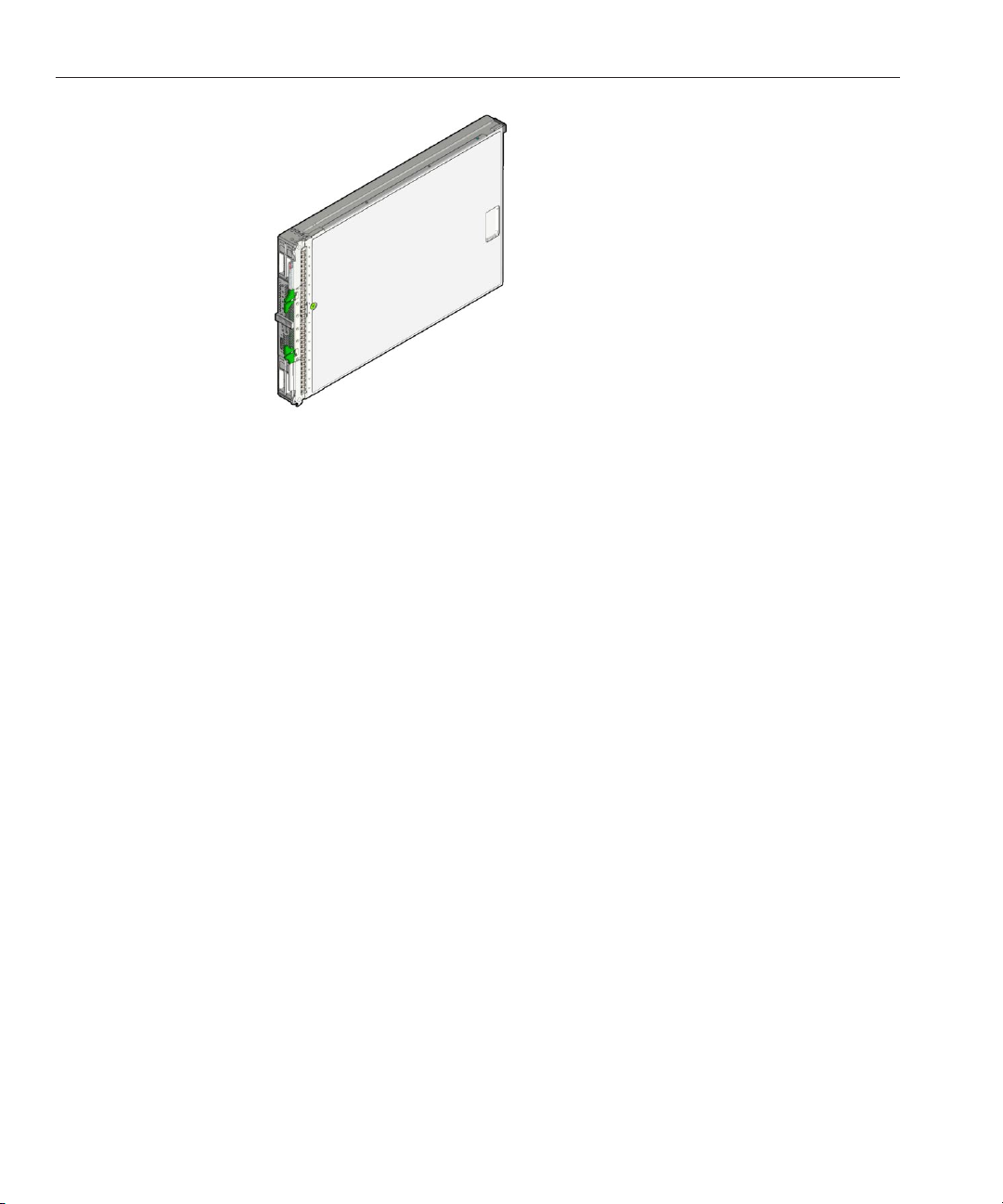
Front Panel Features
The following illustration shows front panel features on the Sun Blade X3-2B.
Sun Blade X3-2B (formerly Sun Blade X6270 M3) Service Manual • May,201412
Page 13

Front Panel Features
Figure Legend
1 Locate button and LED – white 8 USB ports (2)
2 Ready to remove LED – blue 9 Universal connector port (UCP)
3 Service action required LED – amber 10 Storage drive (HDD 0)
4 Power OK LED – green 11 Storage drive (HDD 1)
5 Power button 12 Storage drive (HDD 2)
6 NMI Reset button (Service only) 13 Storage drive (HDD 3)
13
Page 14

Front PanelLEDs and Buttons
Figure Legend
7 RFID tag (with serial number) 14 Ejectorlevers
Related Information
■
“Front Panel LEDs and Buttons” on page 14
■
“Identifying Storage Drive LEDs and Mechanical Components” on page 47
■
“Rear Panel Features” on page 20
Front Panel LEDs and Buttons
The topics included in this section show the location of the front panel LEDs and buttons and
describe their functions.
Location of Front Panel LED and Buttons
This illustration shows the location of the front panel LEDs and buttons.
Sun Blade X3-2B (formerly Sun Blade X6270 M3) Service Manual • May,201414
Page 15

Front PanelLEDs and Buttons
The descriptions and functions are described below.
Locate LED Button
15
Page 16

Front PanelLEDs and Buttons
Functionality:
■
Combination white LED and button.
■
The Locate LED button is used to activate the Locate LED to identify a server module within
a chassis.
■
The Locate LED button is also used for some Oracle ILOM procedures.
■
Press the Locate LED button to activate the Locate LED. You can also remotely activate the
Locate LED from Oracle ILOM.
■
See “Managing the Locate LED”on page 35.
Ready ToRemove LED
Sun Blade X3-2B (formerly Sun Blade X6270 M3) Service Manual • May,201416
Page 17

Front PanelLEDs and Buttons
Functionality:
■
Blue LED.
■
Indicates when it is safe to remove the server module from the chassis.
■
O: Normal operation. Do not remove the server module.
■
On solid: The server module is ready to remove. See “Remove the Server Module from the
Sun Blade Chassis” on page 36
.
Service Action Required LED
17
Page 18

Front PanelLEDs and Buttons
Functionality:
■
Amber LED.
■
Service Action Required LED indicates a server module fault.
■
O: Normal operation.
■
On solid: The server module has a fault. See “Troubleshooting the Sun Blade X3-2B” on
page 107
.
PowerOK LED and Button
Sun Blade X3-2B (formerly Sun Blade X6270 M3) Service Manual • May,201418
Page 19

Front PanelLEDs and Buttons
Functionality:
■
Green LED.
■
Power button is used to toggle the server between standby power and full power mode.
■
Operation of the Power button requires the use of a stylus.
■
The Power/OK LED indicates the status of the server power.
■
LED states:
■
Service processor is starting: Fast blink
■
Host is booting: Slow blink at 1 Hz.
■
Standby power mode: Blink 0.2 seconds on, 2.8 seconds o
■
Full power mode: On solid (does not blink)
■
Press to power the server module on or o. See “Powering O the Server Module” on
page 28
or “PoweringOn the Server Module” on page 103.
NMI Button
19
Page 20

Rear Panel Features
Functionality:
The NMI (non-maskable interrupt) button is for service use only. Do not press.
Related Information
■
“Front Panel Features” on page 12
■
“Rear Panel Features” on page 20
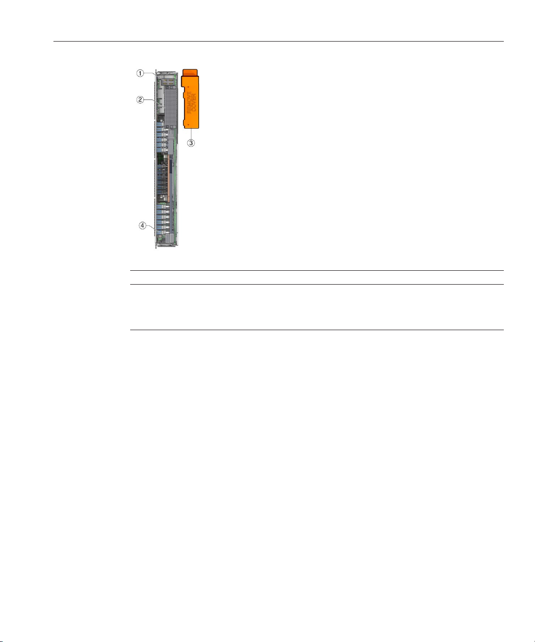
Rear Panel Features
The following illustration shows rear panel features on the Sun Blade X3-2B.
Sun Blade X3-2B (formerly Sun Blade X6270 M3) Service Manual • May,201420
Page 21
About the System Chassis
Figure Legend
1 Power connector 3 Protective shipping cover for rear connector
(remove before inserting into chassis)
2 I/O connector 4 USB ash drives 2, 3 (P0 and P1)
Related Information
■
“Front Panel Features” on page 12
■
“Front Panel LEDs and Buttons” on page 14
■
“About the System Chassis” on page 21
About the System Chassis
The Sun Blade X3-2B is used in a Sun Blade 6000 chassis. When fully loaded, the Sun Blade 6000
chassis can hold a combination of up to ten server modules and blades. Power limitations apply
to the number of server modules that can be installed in a Sun Blade 6000 modular system. For
more information about the Sun Blade X3–2B conguration and compatibility, see
Server Module Components” in Sun Blade X3-2B (formerly Sun Blade X6270 M3) Product
.
Notes
Related Information
■
Sun Blade 6000 Modular System Chassis documentation (http://www.oracle.com/pls/
topic/lookup?ctx=sb6000)
“Supported
.
21
Page 22

About Oracle ILOM
About Oracle ILOM
Oracle Integrated Lights Out Manager (Oracle ILOM) is system management rmware that is
preinstalled on an embedded service processor (SP) on Oracle's x86- and SPARC-based servers.
Oracle ILOM enables you to actively manage and monitor components in the server in both
standby power and full power modes. Using Oracle ILOM, you can remotely manage and
monitor the server as if you were using a locally attached keyboard, monitor, and mouse. The
Oracle ILOM rmware automatically initializes when standby power is applied to the server.
Oracle ILOM allows you to choose either a command-line interface (CLI) or a browser-based
interface.
Note – The chassis also has Oracle ILOM installed on the chassis monitoring module (CMM),
which is used to manage chassis functions.
With Oracle ILOM, you can:
■
Monitor the status of server module sensors and indicators.
■
Monitor hardware errors and faults and send events using SNMP traps or e-mail alerts when
faults occur.
■
Remotely control the power state of your server module.
■
Congure the server module BIOS settings.
The SP has a dedicated Ethernet port, and it runs its own Oracle ILOM embedded OS,
providing out-of-band management capability. In addition, you can access Oracle ILOM from
the server's host OS.
Sun Blade X3-2B (formerly Sun Blade X6270 M3) Service Manual • May,201422
Page 23

About the Chassis Monitoring Module (CMM)
Related Information
■
“About the Chassis Monitoring Module (CMM) ” on page 23
■
Oracle Integrated Lights Out Manager (ILOM) 3.1 Documentation Collection
(http://www.oracle.com/pls/topic/lookup?ctx=ilom31).
■
“Oracle Integrated Lights Out Manager (ILOM)” in Sun Blade X3-2B (formerly Sun Blade
X6270 M3) Administration Guide
About the Chassis Monitoring Module (CMM)
The chassis monitoring module (CMM) provides a common management interface for each
server module. The CMM is the primary point of management interaction for all shared chassis
components and functions.
The CMM indicator panel is located on the rear of the chassis.
Each blade is assigned an IP address that is used for CMM management. IP addresses for server
module blades are assigned by static or DHCP methods.
Related Information
■
Sun Blade 6000 Modular System documentation (http://www.oracle.com/
us/products/servers-storage/servers/blades/sun-blade-6000-chassis/overview/
index.html)
■
Oracle Integrated Lights Out Manager (ILOM) 3.1 Documentation Collection
(http://www.oracle.com/pls/topic/lookup?ctx=ilom31)
.
23
Page 24

Replaceable Server Module Components
Replaceable Server Module Components
This section includes an illustrated parts breakdown, replaceable component (CRU and FRU)
list, and information about component serviceability.
The following topics are covered:
■
“Illustrated Parts Breakdown” on page 24
■
“Replaceable Components (FRUs and CRUs)” on page 25
■
“Component Serviceability” on page 26
Illustrated Parts Breakdown
The following illustration and table identies Sun Blade X3-2B internal components.
Figure Legend
1 Storage drives (4
maximum, HDD or SSD)
2 RAID expansion module
(REM)
3 Processors (0 and 1) 8 System battery (type: CR2032 )
4 Heat sink assemblies (0
and 1)
Sun Blade X3-2B (formerly Sun Blade X6270 M3) Service Manual • May,201424
6 USB 2.0 drives (0 and 1)
7 DIMMs DDR3 LV (24 maximum)
9 Server module enclosure (Includes motherboard, disk
backplane, and enclosure assembly.)
Page 25

Figure Legend
Replaceable Components (FRUs and CRUs)
5 Fabric expansion modules
(FEM)
Note – FEMs are available
in two possible form
factors (single-width and
double-width).
10 REM storage drive cable
Related Information
■
“Replaceable Components (FRUs and CRUs)” on page 25
■
“Component Serviceability” on page 26
Replaceable Components (FRUs and CRUs)
The replaceable components in your Sun Blade X3-2B are designated as either eld-replaceable
units (FRU) or customer-replaceable units (CRU). A part designated as a FRU must be replaced
by an Oracle-qualied service technician. A part designated as a CRU can be replaced by a
person who is not an Oracle-qualied service technician. The following table lists the FRU and
CRU components.
Component Description Designation
HDDs or SSDs (and llers) CRU
DIMMs (and llers) CRU
Battery, system CRU
USB 2.0 drives (rear) CRU
FEM CRU
REM CRU
REM storage drive cable CRU
Processor and heat sink assembly (CPU) FRU
Motherboard and blade enclosure assembly FRU
Related Information
■
“Illustrated Parts Breakdown” on page 24
■
“Component Serviceability” on page 26
25
Page 26

Component Serviceability
Component Serviceability
Components are either hot serviceable or cold serviceable.
■
Hot service capability allows you to safely remove this component while the server module
is running.
■
Cold service capability requires you to remove the server module from service.
The following table lists the serviceability of components.
Component Description Serviceability
HDDs or SSDs (and llers)
DIMMs (and optional llers) Cold
Battery, system Cold
USB 2.0 drives (rear) Cold
FEM Cold
REM Cold
REM storage drive cable Cold
1
Hot
Processor and heat sink assembly (CPU) Cold
Motherboard and blade enclosure assembly Cold
1
Before removing consult your operating system for instructions on safe removal.
Related Information
■
“Illustrated Parts Breakdown” on page 24
■
“Replaceable Components (FRUs and CRUs)” on page 25
Sun Blade X3-2B (formerly Sun Blade X6270 M3) Service Manual • May,201426
Page 27

Preparing the Sun Blade X3-2B for Service
This section describes how to safely prepare the Sun Blade X3-2B for service and component
removal and replacement. Power information and procedures are also included:
■
“Obtaining the Server Module Serial Number ” on page 27
■
“Powering O the Server Module” on page 28
■
“Performing ESD and Antistatic Prevention Measures” on page 33
■
“Set Up for ESD Prevention” on page 34
■
“Managing the Locate LED” on page 35
■
“Remove the Server Module from the Sun Blade Chassis” on page 36
■
“Remove the Server Module Top Cover” on page 39
■
“Removing or Inserting Filler Panels” on page 40
■
“About the Multi-port Cable” on page 42
■
“Attach a Dongle Cable” on page 43
Obtaining the Server Module Serial Number
To obtain support for your server module, you need the serial number.
The serial number (SysSN) is located on the front panel of the server module on an RFID label,
as shown in the following gure.
27
Page 28

PoweringO the Server Module
Note – The serial number is also visible on the top of the server module. Access requires server
module removal.
Related Information
■
“Front Panel Features” on page 12
■
“Powering O the Server Module” on page 28
Powering O the Server Module
This section contains information and procedures related to power and powering o the server
module:
■
“Power Modes” on page 28
■
“Graceful Power O Using the Power Button” on page 29
■
“Immediate Power O Using the Power Button” on page 29
■
“Complete Power Removal” on page 30
■
“Remote PowerO Using Oracle ILOM SP CLI” on page 31
■
“Remote PowerO Using Oracle ILOM SP Web Interface” on page 32
Power Modes
The Sun Blade X3-2B has two power modes, full power mode and standby power mode.
Sun Blade X3-2B (formerly Sun Blade X6270 M3) Service Manual • May,201428
Page 29

BeforeYou Begin
Full power mode is the normal operational mode for the server. When the server enters full
power mode, power is supplied to all the server components, the server boots, and the operating
system (OS) functions. You achieve full power mode by pressing the Power button on the server
front panel when the server is in standby power mode. You can also achieve full power mode by
powering on the server from Oracle ILOM. Once the server is operating in full power mode, the
Power OK LED is on continuously (does not blink).
Standby power is a non-operating mode, where minimum power is supplied to the components
that are required to run the service processor (SP), but the OS is not booted. To enter standby
power mode, install the server into a fully-powered chassis, but do not press the front panel
Power button. You can also enter standby power mode by powering o the server (from an
operational full power mode) using one of the power-o methods (see below). In standby
power mode, the front panel Power LED blinks quickly while the SP is booting, and slowly
when the SP has booted.
▼
Graceful PowerO Using the Power Button
Note – This procedure is performed locally requiring access to the server module front panel.
Pressing the Power button causes operating systems with Advanced Conguration and Power
Interface (ACPI) to perform an orderly shutdown of the OS. Server modules not running
ACPI-enabled operating systems might ignore this event, and the host does not shut down.
■
“Front Panel LEDs and Buttons” on page 14
■
“Power Modes” on page 28
PowerModes
See Also
Use a stylus, to gently press and releasethe Power button on the front panel.
1
See the illustration in
Verify that the full power is o.
2
“Powering O the Server Module” on page 28.
The OK LED on the front panel blinks, indicating that the server module is in standby power
mode.
■
“Manage the Locate LED Remotely From Oracle ILOM SP Web Interface” on page 35
■
“Manage the Locate LED Remotely From Oracle ILOM CLI” on page 36
■
“Complete Power Removal” on page 30
▼
Immediate Power O Using the Power Button
This procedure is performed locally requiring access to the server module front panel.
29
Page 30

PowerModes
BeforeYou Begin
See Also
Caution – Data loss. All applications and les will be closed abruptly without changes being
saved.
■
“Front Panel LEDs and Buttons” on page 14
■
“Power Modes” on page 28
Use a stylus to press and hold the Power button for at least ve seconds until the full power is o
1
and the server module enters standby power mode.
Verify that the full power is o, and that the OK LED on the front panel blinks, indicating that the
2
server module is in standby power mode.
“Front Panel LEDs and Buttons” on page 14.
See
■
“Manage the Locate LED Remotely From Oracle ILOM SP Web Interface” on page 35
■
“Manage the Locate LED Remotely From Oracle ILOM CLI” on page 36
■
“Complete Power Removal” on page 30
▼
Complete Power Removal
Powering the server module from full power mode to standby power mode does not power o the
server completely. In some situations, it might be necessary to remove power from the server
module and place it in an non-powered state. To do this, you must disengage the server module
from the chassis backplane by partially removing it.
BeforeYou Begin
Use this procedure to remove power from the server module by partially removing it from the
chassis.
“Remove the Server Module from the Sun Blade Chassis” on page 36.
See
Place the server module in standby power mode.
1
“Powering O the Server Module” on page 28.
See
To partially remove the servermodule, pull it out approximately 3 inches (8 cm) from the rack
2
using the ejector levers.
Caution – Component damage or data loss. Server modules should be removed only if the blue
Ready to Remove LED is lit, or if you are certain that a rmware update is not in progress.
Pulling the server module out of the chassis during a rmware update might damage the server
module, which might not be repairable in the eld.
Alternatively, you can remove the server module from the chassis.
Sun Blade X3-2B (formerly Sun Blade X6270 M3) Service Manual • May,201430
Page 31

See Also
If you completelyremove the servermodule from the chassis, insert a ller panel in its place
3
within 60 seconds.
Caution – Component damage or data loss. Do not insert a server module into the chassis until at
least 20 seconds has elapsed since the server module was disengaged from the midplane
connector.
■
“Graceful Power O Using the Power Button” on page 29
■
“Immediate Power O Using the Power Button” on page 29
■
“Remote PowerO Using Oracle ILOM SP CLI” on page 31
■
“Remote PowerO Using Oracle ILOM SP Web Interface” on page 32
■
Oracle Integrated Lights Out Manager (ILOM) 3.1 Documentation Collection
(http://www.oracle.com/pls/topic/lookup?ctx=ilom31)
▼
Remote Power O Using Oracle ILOM SP CLI
You can use the service processor command-line interface (CLI) to remotely perform power o
the server module.
Log into the server module host OS as a superuser or equivalent.
1
Depending on the type of problem, you might want to view server module status or log les, or
run diagnostics before you shut down the server module.
PowerModes
Notify users of impending power-o.
2
Save any open les and quit all running programs.
3
Refer to your application documentation for specic information.
Open an SSH session to the SP.
4
Log in to the serviceprocessor CLI interface.
5
“Access Oracle ILOM Using CLI” in Sun Blade X3-2B (formerly Sun Blade X6270 M3)
See
Administration Guide
.
The default user name is root, and the password is changeme.
The CLI prompt appears:
->
At the prompt,type one of the followingcommands:
6
■
For graceful power o:
31
Page 32

PowerModes
See Also
stop /System
■
For immediate power o:
stop -force /System
■
“Graceful Power O Using the Power Button” on page 29
■
“Immediate Power O Using the Power Button” on page 29
■
“Complete Power Removal” on page 30
■
Oracle Integrated Lights Out Manager (ILOM) 3.1 Documentation Collection
(http://www.oracle.com/pls/topic/lookup?ctx=ilom31)
▼
Remote Power O Using Oracle ILOM SP Web Interface
You can use the service processor web interface to perform a graceful shutdown of the server
module.
Log in as a superuser or equivalent to the servermodule host OS.
1
Depending on the type of problem, you might want to view server module status, view log les,
or run diagnostics before you shut down the server module.
Notify users of impending power-o.
2
Save any open les and quit all running programs.
3
Refer to your application documentation for specic information.
Log in to the serviceprocessor web interface.
4
See
“Access Oracle ILOM Using a Web Browser” in Sun Blade X3-2B (formerly Sun Blade X6270
M3) Administration Guide
.
The default user name is root, and the password is changeme.
Sun Blade X3-2B (formerly Sun Blade X6270 M3) Service Manual • May,201432
Page 33

Performing ESD and Antistatic Prevention Measures
The Summary screen appears.
5
In the Actions section of the Summary screen, verify that the powerstate is ON.
6
To performa graceful powero of the server, click the Turn Obutton.
Alternatively, other power o options are available in the Host Management > Power Control
screen.
Click OK.
7
See Also
Oracle Integrated Lights Out Manager (ILOM) 3.1 Documentation Collection
(http://www.oracle.com/pls/topic/lookup?ctx=ilom31)
Performing ESD and Antistatic Prevention Measures
The section contains important electrostatic discharge and antistatic information.
Caution – Component damage. Circuit boards and drives contain electronic components that
are extremely sensitive to static electricity. Ordinary amounts of static electricity from clothing
or the work environment can destroy the components located on these boards. As a minimum
precaution, do not touch the component's connector edges.
Using an Antistatic Wrist Strap and an Antistatic Mat
Wear an antistatic wrist strap and use an antistatic mat when handling components such as
storage drive assemblies, circuit boards (including DIMMs), or PCIe cards. When servicing or
removing server components, place an antistatic strap to your wrist and attach the clip end to a
bare metal area on the chassis. Following this practice equalizes the electrical potentials between
you and the server. Addtionally, always place ESD-sensitive components an antistatic mat or
antistatic packaging.
33
Page 34

Performing ESD and Antistatic Prevention Measures
Note – An antistatic wrist strap is not included in the accessory kit for the Sun Blade X3-2B.
However, antistatic wrist straps are included with optional components.
Related Information
“Set Up for ESD Prevention” on page 34
▼
Set Up for ESD Prevention
Prepare an antistatic surface to set parts on during the removal, installation, or replacement
1
process.
Place ESD-sensitive components such as the printed circuit boards on an antistatic mat. The
following items can be used as an antistatic mat:
■
Antistatic bag used to wrap an Oracle replacement part
■
An ESD mat
■
A disposable ESD mat (shipped with some replacement parts or optional system
components)
2
Attach an antistatic wrist strap.
When servicing or removing server module components, attach an antistatic strap to your wrist
and then to a metal area on the chassis.
Sun Blade X3-2B (formerly Sun Blade X6270 M3) Service Manual • May,201434
Page 35

Managing the Locate LED
See Also
“Performing ESD and Antistatic Prevention Measures” on page 33.
Managing the Locate LED
The Locate LED/button is located on the server module front panel (see “Front Panel LEDs and
BeforeYou Begin
Buttons” on page 14
server (locally) or use Oracle ILOM to remotely manage it. For example, you can use Oracle
ILOM to turn on the Locate LED to nd a specic server within a chassis. Then, you can turn
the Locate LED o, locally (or remotely) once you've found the server.
Note – Some Oracle ILOM procedures contain steps that require you to activate the Locate LED
locally.
This section contains the following procedures for managing the Locate LED Button:
■
“Manage the Locate LED Locally” on page 35
■
“Manage the Locate LED Remotely From Oracle ILOM SP Web Interface” on page 35
■
“Manage the Locate LED Remotely From Oracle ILOM CLI” on page 36
▼
Manage the LocateLED Locally
“Front Panel LEDs and Buttons” on page 14
To activateor deactivate the Locate LED, press the LocateLED button.
●
). You can manually activate and deactivate the LED button while at the
See Also
▼
Manage the LocateLED Remotely From Oracle ILOM SP Web Interface
Log in to the Oracle ILOMservice processor web interface.
1
“Access Oracle ILOM Using a Web Browser” in Sun Blade X3-2B (formerly Sun Blade X6270
See
M3) Administration Guide
.
The Oracle ILOM screen appears.
Select the server module.
2
The Oracle ILOM Summary screen appears.
3
In the Actions section, verify that the Locatorindicator is o, and then click the Turn On button.
4
Click OK.
The Locator indicator on the Summary screen changes to indicate the status of the Locate LED.
■
“Manage the Locate LED Remotely From Oracle ILOM CLI” on page 36
35
Page 36

Managing the Locate LED
▼
1
2
3
■
Oracle Integrated Lights Out Manager (ILOM) 3.1 Documentation Collection
(http://www.oracle.com/pls/topic/lookup?ctx=ilom31)
Manage the LocateLED Remotely From Oracle ILOM CLI
Log in to the Oracle ILOMCLI.
See
“Access Oracle ILOM Using CLI” in Sun Blade X3-2B (formerly Sun Blade X6270 M3)
Administration Guide
The CLI prompt appears:
–>
Typeone of the following commands:
■
To turn on the Locate LED, type:
–> set /System/ locator_indicator=on
■
To turn o the Locate LED, type:
–> set /System/ locator_indicator=off
To verify the status of the Locate LED, type:
–> show /System/ locator_indicator
.
See Also
The output of the command appears:
/System
Properties:
locator_indicator = Off
The value locator_indicator shows the status as either On or Off.
■
“Manage the Locate LED Remotely From Oracle ILOM SP Web Interface” on page 35
■
Oracle Integrated Lights Out Manager (ILOM) 3.1 Documentation Collection
(http://www.oracle.com/pls/topic/lookup?ctx=ilom31)
▼
Remove the Server Module from the Sun Blade Chassis
The server module must be removed from the Sun Blade 6000 chassis to:
■
Service CRU and FRU internal system components such as: system battery, cables, rear USB
drives, DIMMs, processors (CPU), REMs and FEMs.
■
Access Fault Remind buttons for processors and DIMMs.
Sun Blade X3-2B (formerly Sun Blade X6270 M3) Service Manual • May,201436
Page 37

Managing the Locate LED
Note – You do not need to remove the server module from the Sun Blade chassis to service
storage drive components on the Sun Blade X3-2B front panel.
Log in to the Oracle ILOMCLI.
1
See
“Access Oracle ILOM Using CLI” in Sun Blade X3-2B (formerly Sun Blade X6270 M3)
Administration Guide
.
The CLI prompt appears: –>
Type:
2
-> set /System/ action=prepare_to_remove
Verify the removal status.Type:
3
-> show /System/ health
/System
Properties:
health = Offline
->
Oine status ensures that no rmware updates are taking place before you remove the blade.
Caution – Component damage or data loss. Server modules should be removed only if the blue
LED is lit, or if you are certain that a rmware update is not in progress. Pulling the server
module out of the chassis during a rmware update might damage the server module, which
might not be repairable in the eld.
Powero the server module or place it in standby powermode.
4
See
“Powering O the Server Module” on page 28.
When the server module is in standby power mode, the OK LED on the front panel blinks (0.1
second on, 2.9 seconds o).
To unlock the server module ejector arms, press the green tabs on the ends of ejector arms.
5
Caution – Component damage or data loss. Do not install a server module into the chassis until
at least 20 seconds has elapsed since the server module was disengaged from the chassis
mid-plane connector.
37
Page 38

Managing the Locate LED
6
7
To disengage the server module from the internal connector, rotate both ejector arms away
from the server module atthe same time until fully extended.
The result of this action disengages the server module, places it in a no-power state, and leaves it
protruding approximately three inches from the front of the chassis.
Caution – Component damage or personal injury. Do not attempt to remove the server module
using only the ejector levers.
Do one of the followingto remove the server module from the chassis:
Caution – Component damage or data loss. Server modules should be removed only if the blue
Ready to Remove LED is lit, or if you are certain that a rmware update is not in progress.
Pulling the server module out of the chassis during a rmware update might damage the server
module, which might not be repairable in the eld.
■
Complete removal: Pull the server module awayfrom the Sun Blade chassis (approximately
5–6 inches) using the ejector arms until you are able to grab the server module with both
hands.To remove, pull the server module out of the chassis using both hands.
Caution – Component damage or personal injury. Blades can weigh up to 22 lbs (10kg). Use
two hands to install or remove the blade from the chassis.
■
Partial removal: Ensure that the servermodule is disengaged from the internal connector and
protruding from the front of the chassis approximately 3 inches (8 cm). If necessary,use the
ejector levers to pull the server module away from the chassis.
Note – This method is used to remove power from the server module. See “Complete Power
Removal” on page 30
Sun Blade X3-2B (formerly Sun Blade X6270 M3) Service Manual • May,201438
.
Page 39

Managing the Locate LED
Set the server module on a at antistatic surface.
8
“Performing ESD and Antistatic Prevention Measures” on page 33.
See
Caution – Component damage. Observe the proper ESD precautions when handling the server
module. Wear a securely grounded ESD wrist strap. Handle components by the edges only. Do
not touch metal contacts. Damage to system components can occur through improper
handling.
Insert a server module ller panel in the unused server slot to ensure properairow throughout
9
the system.
“Insert Server Module Filler Panels” on page 41.
See
Caution – Over-temperature condition. Always insert a server module ller panel into an empty
slot within 60 seconds to reduce the possibility of server module shutdown. Do not operate the
chassis with empty slots. If you operate the chassis with an empty server module slot, you might
notice a reduction in system performance. Possible system and component over-temperature
warnings, shutdown, and heat-related damage might be caused by empty chassis slots.
See Also
Next Steps
Oracle Integrated Lights Out Manager (ILOM) 3.1 Documentation Collection
(http://www.oracle.com/pls/topic/lookup?ctx=ilom31)
“Remove the Server Module Top Cover” on page 39
▼
Remove the Server Module Top Cover
You need to remove the server module cover to service components inside the Sun Blade
X3-2B.
Note – You do not need to remove the top cover to access storage drives and internal USB 2.0
drives.
Powero the server module.
1
“Powering O the Server Module” on page 28.
See
Remove the servermodule from the chassis.
2
“Remove the Server Module from the Sun Blade Chassis” on page 36.
See
Attach an antistatic wrist strap.
3
“Performing ESD and Antistatic Prevention Measures” on page 33.
See
39
Page 40

Removing or Inserting Filler Panels
Press down on the server module cover release button and, using the indent for leverage, slide
4
the top covertowardthe rear of the servermodule chassis approximately0.5 inch (12 mm).
Grasp the server module coverby its rear edge. Lift the cover straight up from the server
5
module.
Next Steps
“Insert Server Module Filler Panels” on page 41
“Servicing Sun Blade X3-2B Components ” on page 45
Removing or Inserting Filler Panels
A ller panel is a metal or plastic enclosure that does not contain any functioning system
hardware or cables. The primary purpose of a ller is to occupy vacant slots to maintain cooling
and proper air ow throughout the system. Do not operate your system with unoccupied slots.
Improper cooling and airow can compromise the operating performance of your system and
quickly damage components.
For server module ller panel removal and installation procedures see the following topics:
Note – For instructions for adding or replacing chassis component ller panels (for example,
network modules or chassis monitoring modules), refer to the documentation supplied with
your chassis.
■
“Component Filler Panels ” on page 41
■
“Remove Server Module Filler Panels” on page 41
■
“Insert Server Module Filler Panels” on page 41
Sun Blade X3-2B (formerly Sun Blade X6270 M3) Service Manual • May,201440
Page 41

Component Filler Panels
Component Filler Panels
In addition to ller panels in the chassis server module slots, each server module arrives with
ller panels for storage drives and optional ller panels for memory modules. These component
ller panels are installed at the factory and must remain in the server module until you are ready
to replace them with a component.
To remove or insert component ller panels, choose one of the following procedures:
■
“Remove Storage Drive Filler Panels” on page 54
■
“Insert Storage Drive Filler Panels” on page 55
■
“Remove Optional DIMM Filler Panels” on page 65
■
“Install Optional DIMM Filler Panels” on page 65
▼
Remove Server Module Filler Panels
Locate the servermodule ller panel to be removed from the chassis.
1
To unlatch the server module ller panel from the chassis, press the button on the release lever
2
handle, and then lower the lever into the fully open position.
See Also
To remove the ller panel from the chassis,hold the release lever,and then gently slide the ller
3
panel toward you.
■
“Component Filler Panels ” on page 41
■
“Remove Server Module Filler Panels” on page 41
■
“Insert Server Module Filler Panels” on page 41
▼
Insert Server Module Filler Panels
Locate the vacant server module slot in the chassis.
1
41
Page 42

About the Multi-port Cable
2
3
4
See Also
Ensure that the release lever is fully opened, and then align the ller panel with the vacant
server module slot.
Slide the ller panel into the vacant server module slot.
As the release lever makes contact with the chassis, the lever will start to close.
Close the release lever until it locks the ller panel in place.
■
“Component Filler Panels ” on page 41
■
“Remove Server Module Filler Panels” on page 41
■
“Insert Server Module Filler Panels” on page 41
About the Multi-port Cable
The multi-port cable (dongle) provides a single multiple-interface access point to the server
module. You can use the multi-port cable to connect devices directly into the universal
connector port (UCP) on the front of the server module for service, maintenance, and OS
installation procedures. Using the multi-port cable, you can work locally at the server and
attach USB, serial, and video devices directly to the server module.
The following illustration shows the interfaces available through the UCP using the
three-connector multi-port cable.
Note – Multi-port cables are available in two varieties, a newer three cable version and a four
cable version
The four-port cable has a DB-9 serial connector, while the three-port cable does not. Your
chassis might ship with a DB-9-to-RJ-45 serial cable adapter. The adapter allows you to attach a
serial cable with a DB-9 connector to the server module using the RJ-45 port on the multi-port
cable.
Sun Blade X3-2B (formerly Sun Blade X6270 M3) Service Manual • May,201442
Page 43

Figure Legend
About the Multi-port Cable
1 DB-15 (video port)
2 RJ-45 (serial management port)
3 USB 2.0 (2 ports)
Related Information
■
Sun Blade X3-2B (formerly Sun Blade X6270 M3) Installation Guide
■
“Attach a Dongle Cable” on page 43
▼
Attach a Dongle Cable
The multi-port cable attaches to the front of the server module using the universal connector
port (UCP). The multi-port cable is designed for temporary attachment. Disconnect the cable
when nished.
Position the multi-port cable connector so the at side of the connector aligns with the at side
1
of the universal connector port (UCP).
43
Page 44

About the Multi-port Cable
2
3
4
Gently squeeze the sides of the multi-port cable connector and insert the multi-portcable into
the UCP on the server module front panel.
Connect the devices using the appropriate interfaces.
For an overview of the available interfaces on the multi-port cable, see
“About the Multi-port
Cable” on page 42.
Caution – Component damage. When not in use, do not leave the cable attached to the server
module. The multi-port cable is designed for temporary use.
To disconnect the multi-portcable, gently squeeze the sides of the cable connector and pull
away from the server module.
Sun Blade X3-2B (formerly Sun Blade X6270 M3) Service Manual • May,201444
Page 45

Servicing Sun Blade X3-2B Components
Note – Some of the procedures in this section are for customer-replaceable units (CRUs) and
some are for eld-replaceable units (FRUs), as noted in the procedures. FRU components must
be replaced only by an Oracle Service technician. Contact your Oracle Service representative for
assistance with FRU replacements. See
.
page 25
This section contains procedures and information about how to safely and eciently remove
and install Sun Blade X3-2B components.
The following sections are covered:
■
“Servicing a Storage Drive (CRU)” on page 45
■
“Servicing DIMMs (CRU)” on page 55
■
“Replace the System Battery (CRU)” on page 66
■
“Servicing USB Flash Drives (CRU)” on page 67
■
“Servicing a Fabric Expansion Module (CRU)” on page 70
■
“Servicing a RAID Expansion Module (CRU)” on page 72
■
“Servicing Cables (CRU)” on page 77
■
“Servicing a Processor and Heat Sink Assembly (FRU)” on page 79
■
“Servicing the Motherboard Assembly (FRU)” on page 93
“Replaceable Components (FRUs and CRUs)” on
Servicing a Storage Drive (CRU)
Note – This component is a hot-swappable customer-replaceable unit (CRU).
Hot-swap capability allows you to safely remove this component while the server module is
running. However, you might have to prepare the server module operating system before you
remove drives.
To remove and install a hard drive (HD) or a solid state drive (SSD), use the following
procedures:
45
Page 46

Identifying Storage Drives
■
“Identifying Storage Drives” on page 46
■
“Identifying Storage Drive LEDs and Mechanical Components” on page 47
■
“About Storage Drive Failure and RAID ” on page 50
■
“About Disk Backplane Cabling” on page 51
■
“Remove a Storage Drive” on page 51
■
“Install a New Storage Drive” on page 52
■
“Replace a Storage Drive” on page 53
■
“Remove Storage Drive Filler Panels” on page 54
■
“Insert Storage Drive Filler Panels” on page 55
Identifying Storage Drives
The system software designation for storage drive devices (hard disk drives [HDD] or solid
state drives [SSD]) is shown in the following gure.
Figure Legend
0 Hard disk drive (HDD 0) 2 Hard disk drive (HDD 2)
1 Hard disk drive (HDD 1) 3 Hard disk drive (HDD 3)
Sun Blade X3-2B (formerly Sun Blade X6270 M3) Service Manual • May,201446
Page 47
Identifying Storage Drive LEDs and Mechanical Components
Related Information
■
“Identifying Storage Drive LEDs and Mechanical Components” on page 47
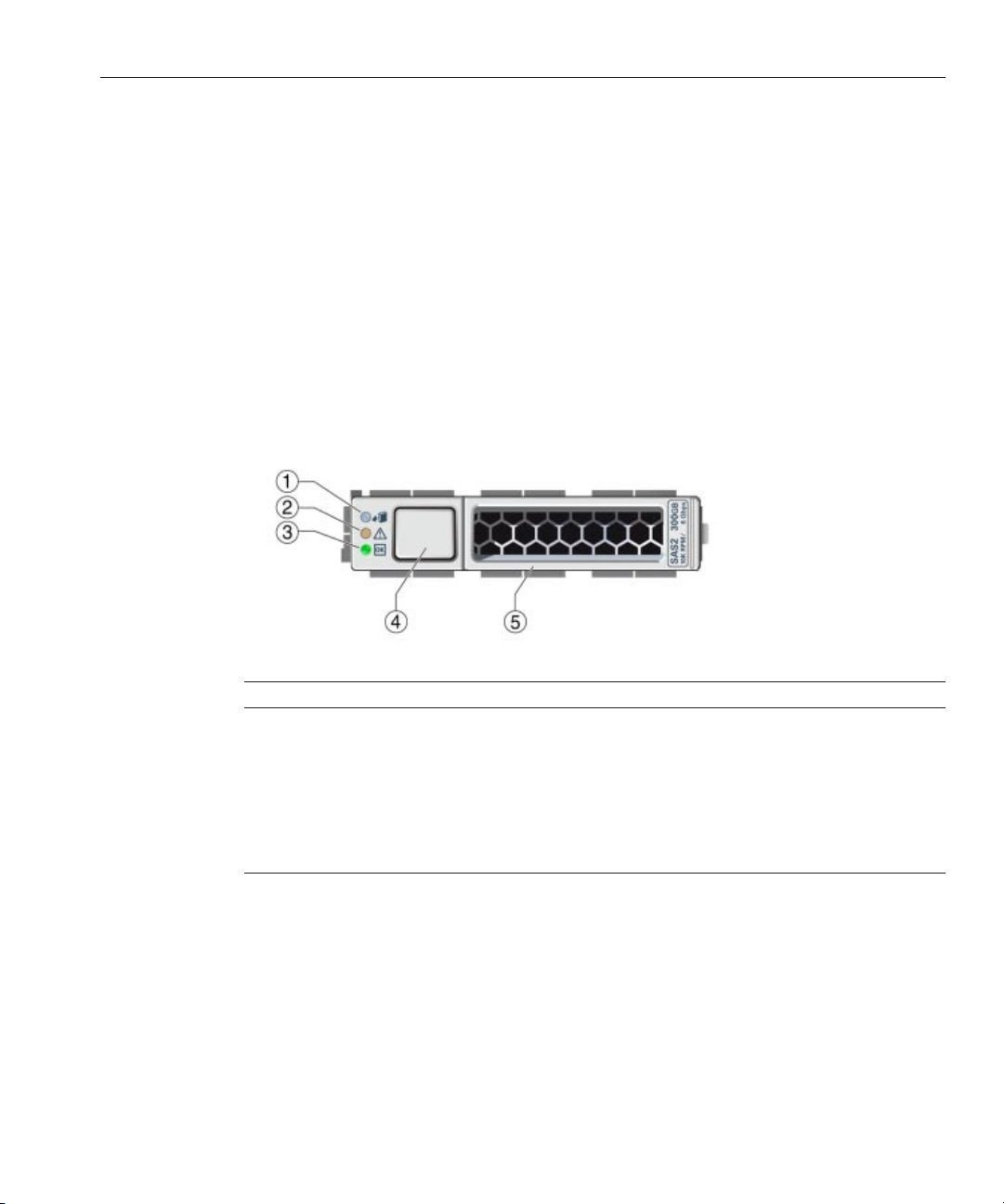
Identifying Storage DriveLEDs and Mechanical
Components
The topics included in this section show the location of the storage drive LEDs and mechanical
components and describe their functions.
Legend Name
1 Ready to Remove LED
2 Service Action Required LED
3 Power/OK LED
4 Lever Release button
5 Lever
The functions of the storage drive LEDs and mechanical components are described below.
Ready to Remove LED
This topic describes the Ready to Remove LED.
47
Page 48

Identifying Storage Drive LEDs and Mechanical Components
Functionality:
■
Blue LED.
■
Conditions:
■
On solid: The storage drive is in standby power mode. The storage drive can be removed
safely during a hot-plug operation. A lit Ready to Remove LED indicates that service
action is allowed on the storage drive. The “prepare_to_remove_status” status is “Ready
(OK to remove).”
■
O: Normal operation. Do not remove the drive.
Service Action Required LED
This topic describes the Service Action Required LED.
Functionality:
■
Amber LED.
■
Conditions:
Sun Blade X3-2B (formerly Sun Blade X6270 M3) Service Manual • May,201448
Page 49

Identifying Storage Drive LEDs and Mechanical Components
■
On solid: The system has detected a fault with the storage drive.
■
O: Normal operation.
Power/OKLED
This topic describes the Power/OK LED.
Functionality:
■
Green LED
■
Identies the power state of the storage drive.
■
Conditions:
■
O: Poweris o or installed drive is not recognized by the system.
■
Blink, variable: Disk activity.
■
On solid (does not blink): The drive is engaged and is receiving full power.
Lever and Lever Release Button
This topic describes the operation and purpose of the storage drive lever and the lever release
button.
49
Page 50

About Storage Drive Failure and RAID
Functionality:
■
Press the lever release button to unlock the lever.
■
When the button is pressed, the spring-loaded lever unlocks and pops open.
■
Lever functions:
■
■
Drive removal: Use the lever to pull the drive out of the server. For more information, see
“Remove a Storage Drive” on page 51.
Drive installation: Use the lever to engage the drive with the internal connector. For
more information, see
“Install a New Storage Drive” on page 52.
Related Information
■
“Identifying Storage Drives” on page 46
About Storage DriveFailure and RAID
A single storage device failure does not cause a data failure if the storage devices are congured
as a mirrored RAID 1 volume (optional). Storage devices, such as HDDs, can be removed, and
when a new storage device is inserted, the contents are automatically rebuilt from the rest of the
array with no need to recongure the RAID parameters. If the replaced storage drive was
congured as a hot-spare, the new HDD is automatically congured as a new hot-spare.
Before you permanently remove a storage device from the server that is part of an active RAID
volume, you should delete the active RAID volume from the storage device. For information
about how to delete a RAID volume, use the appropriate RAID management utility for the
RAID controller installed.
Sun Blade X3-2B (formerly Sun Blade X6270 M3) Service Manual • May,201450
Page 51

About Disk Backplane Cabling
Caution – Data loss. If you insert a storage device that has been congured with a RAID volume
into a server that did not previously have its storage devices congured with RAID volumes, the
existing storage devices in the server will be converted to RAID volumes during automatic
synchronization, and any existing data on the existing storage devices in the server is erased.
Related Information
■
“Conguring RAID” in Sun Blade X3-2B (formerly Sun Blade X6270 M3) Administration
Guide
About Disk Backplane Cabling
The server has two internal disk backplanes. The right-side backplane supports drives HD 0 and
HD 1. The left–side backplane supports drives HD 2 and HD 3. Each backplane has three
connectors, one 10-pin power connector and two color-coded data connectors (one for each
drive). Backplane power and data cables connect from connectors on the backplane to
connectors on the motherboard. Cabling for the two disk backplanes is described below.
■
Disk backplane for HD 0 and 1:
■
Backplane power: the cable connects to the nearby DBP Power connector on the MB.
■
Blue connector on the backplane (HD 0): cable connects to the REM 0 connector on the
MB.
■
Black connector on the backplane (HD 1): cable connects to the REM 1 connector on the
MB.
■
Disk backplane for HD 2 and 3:
■
Backplane power: the cable connects to the nearby DBP Power connector on the MB.
■
Blue connector on the backplane (HD 2) : cable connects to the REM 2 connector on the
MB.
■
Black connector on the backplane (HD 3): cable connects to REM 3 on the MB.
▼
Remove a Storage Drive
If necessary, prepare the server module operating system before you remove drives.
1
Refer to the OS documentation.
2
Locate the storage drive in the server module bays.
For drive locations on the server module, see
“Identifying Storage Drives” on page 46.
51
Page 52

About Disk Backplane Cabling
View the storage drive front panel LEDs to identify the faultydrive in the server module.
3
Ensure that the blue Ready to Remove LED is lit. See
Mechanical Components” on page 47
Press the release lever button on the drive front panel, and then tilt the lever into a fully opened
4
position.
Hold the opened release lever and gently slide the drive towardyou.
5
If you arenot immediately replacing the drive, insert a ller panel into the empty driveslot on
6
the server.
Caution – Over-temperature condition. Do not operate the server with empty storage device
slots. Always insert a ller panel into an empty storage device slot. See
Filler Panels” on page 55
“Identifying Storage Drive LEDs and
.
“Insert Storage Drive
.
Next Steps
“Replace a Storage Drive” on page 53
▼
Install a New Storage Drive
Locate the storage drive ller panels in the server module bays.
1
For drive locations on the server, see
Remove the storage drive ller panels from the server module bays.
2
For instructions to remove drive ller panels, see
“Identifying Storage Drives” on page 46.
“Remove Storage Drive Filler Panels” on
page 54.
Ensure that the storage drive releaselever on the drive is in a fully opened position.
3
Sun Blade X3-2B (formerly Sun Blade X6270 M3) Service Manual • May,201452
Page 53

About Disk Backplane Cabling
Slide the storage drive into the vacant slot by pressing the middle of the storage drive faceplate
4
with your thumb or nger until the release lever engages with the chassis.
The release lever starts to close as it makes contact with the chassis. Do not slide the storage
drive in all the way. Leave the storage drive out approximately 0.25 to 0.50 inch (6 to 12 mm)
from the opening.
Close the release lever until the storage drive clicks into place and is ush with the front of the
5
server.
A pawl near the hinge on the lever engages the sidewall drawing the drive inward and seating
the drive connector with the internal hard drive backplane connector.
▼
Replace a Storage Drive
Remove a ller panel or storage drive from the storage device slot in the server module.
1
Ensure that the storage drive releaselever is in a fully opened position.
2
Slide the storage drive into the vacant slot by pressing the middle of the storage drive faceplate
3
with your thumb or nger until the release lever engages with the chassis.
The release lever will start to close as it makes contact with the chassis. Do not slide the storage
drive in all the way. Leave the storage drive out approximately 0.25 to 0.50 inch (6 to 12 mm)
from the opening.
53
Page 54

About Disk Backplane Cabling
Close the release lever until the storage drive clicks into place and is ush with the front of the
4
server.
Note – If the storage devices were previously congured as a mirrored RAID 1 array, an
automatic resynchronization is invoked and the contents are automatically rebuilt from the rest
of the array with no need to recongure the RAID parameters. If the replaced storage device was
congured as a hot-spare, the new HDD is automatically congured as a new hot-spare.
▼
Remove Storage Drive Filler Panels
Locate the storage drive ller panel to be removedfrom the server.
1
Filler panels have no button on the drive front panel.
To unlatch the storage drive ller panel, press the release leverbutton, and then tilt the lever up
2
into the fully opened position.
To remove the ller panel from the slot,hold the opened release lever and gently slide the ller
3
panel toward you.
Sun Blade X3-2B (formerly Sun Blade X6270 M3) Service Manual • May,201454
Page 55

Servicing DIMMs (CRU)
▼
Insert Storage Drive Filler Panels
Locate the vacant storage drive module slot in the server module.
1
Ensure that the release lever on the ller panel is fully opened.
2
Slide a standard storage drive ller panel into the vacant storage drive slot.
3
Press the middle of the ller panel faceplate with your thumb or nger until the release lever
engages with the chassis.
The release lever starts to close as it makes contact with the chassis. Do not slide the ller panel
in all the way. Leave the ller panel out approximately 0.25 to 0.50 inch (6 to 12 mm) from the
opening.
Caution – Component damage. Do not insert an XL size ller panel.
Close the release lever until it clicks into place and is ush with the front of the server.
4
Servicing DIMMs (CRU)
Note – This component is a customer-replaceable unit (CRU).
This section describes how to diagnose, remove, and install DDR3 LV DIMMs in the Sun Blade
X3-2B.
To watch a video that shows how to remove and install a DIMM, see
Overview Video
Use these procedures to service DIMMs:
■
“DIMM Fault Remind Circuit” on page 56
■
“Identify Faulty DIMMs” on page 57
■
“DIMM Population Rules and Guidelines” on page 58
■
“Remove DIMMs” on page 62
■
“Install DIMMs” on page 63
■
“Remove Optional DIMM Filler Panels” on page 65
■
“Install Optional DIMM Filler Panels” on page 65
.
DIMM Replacement
55
Page 56

DIMM Fault Remind Circuit
DIMM Fault Remind Circuit
The following topics describe the components of the Fault Remind circuitry.
FaultRemind Button and Charge Status LED
Note – Do not press the white Clear CMOS Button (SW1801).
The blue Fault Remind button (SW3001) is located on the motherboard next to the Charge
Status LED (CR3002). The Charge Status LED indicates the usability of the processor test
circuit. When the Fault Remind button is pressed, the Charge Status LED, lights green to
indicate that there is sucient voltage present in the fault remind circuit to activate the fault
LEDs. DIMM Fault LEDs identify DIMMs in a fault state.
Note – Press the fault remind circuitry within 15 minutes of removing the server from the
chassis. If the green Charge Status LED fails to light when you press the Fault Remind button, it
is likely that the fault remind circuit has lost its charge.
DIMM Fault LEDs
The DIMM Fault LEDs are located on the on the motherboard next to each DIMM slot. The
amber LEDs light up when the Fault Remind button is pressed and a DIMM fault condition
exists.
Sun Blade X3-2B (formerly Sun Blade X6270 M3) Service Manual • May,201456
Page 57

Related Information
DIMM Fault Remind Circuit
■
“Using the DIMM and Processor Test Circuit ” on page 108
■
“Identify Faulty DIMMs” on page 57
▼
Identify Faulty DIMMs
Prepare the servermodule for service.
1
See
“Preparing the Sun Blade X3-2B for Service ” on page 27.
Caution – Component damage. This procedure requires that you handle components that are
sensitive to static discharge. This sensitivity can cause the component to fail. To avoid damage,
ensure that you follow electrostatic discharge safety measures and antistatic practices. See
“Performing ESD and Antistatic Prevention Measures” on page 33.
Verify that the charge status LED is lit green.
2
A lit green Charge Status LED, located next to the Fault Remind button, indicates that the Fault
Remind LED circuit is operational.
57
Page 58

DIMM Population Rules and Guidelines
Note – The Charge Status LED indicates the test circuit power level. If the Charge Status LED is
out, the Fault Remind LEDs can not function. After the server module is inserted into the Sun
Blade chassis, the test circuit will recharge. However, any DIMM errors must reoccur to be
stored and visible on a DIMM Fault LED during the next fault remind test.
To identify a faulty DIMM, press and hold the blue Fault Remind button on the motherboard
3
(SW3001).
Release the button after an amber DIMM Fault LED lights. Do not hold the Fault Remind
button down longer than necessary.
Next Steps
See Also
For information about using the DIMM test circuit, see
Circuit ” on page 108
4
Note the location of the faulty DIMMs on the motherboard.
.
“Using the DIMM and Processor Test
A lit amber LED next to a DIMM slot indicates a faulty DIMM.
LED State DIMM Status
O Operating properly, if the DIMM test circuit is ready
to use
On (amber) Faulty and should be replaced.
Ensure that all DIMMs are seated correctly in their connector slots.
5
If re-seating the DIMM does not x the problem, remove and replace the faulty DIMM.
Note – The DIMM Fault LED remains on when the Fault Remind button is pressed after the
DIMM is re-seated. The server module must be powered up again to verify if re-seating xes the
DIMM problem.
“Remove DIMMs” on page 62
■
“DIMM Population Rules and Guidelines” on page 58
■
“Using the DIMM and Processor Test Circuit ” on page 108
DIMM Population Rules and Guidelines
Use these DIMM guidelines and illustrations to help you plan the memory conguration of the
Sun Blade X3-2B.
Sun Blade X3-2B (formerly Sun Blade X6270 M3) Service Manual • May,201458
Page 59

DIMM Population Rules and Guidelines
Basic Memory Guidelines
When populating DIMM slots, follow these population rules and guidelines.
■
Each processor has four DDR3 memory channels (or buses).
■
Each DDR3 memory channel supports up to three DIMMs for a total of 12 DIMMs per
processor.
■
The server module supports one DIMM per channel, two DIMMs per channel, and three
DIMMs per channel across all sockets. Minimum per processor: 1, Maximum per processor:
12.
■
The minimum supported memory conguration is one DIMM per processor D0.
■
The maximum supported memory conguration is 384 GB.
■
Use 8 GB DDR3–1600 LV DIMMs and 16 GB DDR3–1600 LV DIMMs only:
■
Install up to four memory channels, with three DIMMs per channel.
■
Install up to 24 DIMMs per server module or up to 12 DIMMs per processor.
■
For optimal performance, install DIMMs in groups of three sockets per channel.
■
Always install DIMMs in ascending order, within a color or group following the “farthest
from processor rst” convention. See the following table:
DIMM Sockets DIMM Slot Location Socket Color
First D0, D3, D6, D9 Blue
Second D1, D4, D7, D10 White
Third D2, D5, D8, D11 Black
■
The following illustration shows the motherboard, DIMM slot numbering and DIMM slot
locations within the Sun Blade X3-2B enclosure.
59
Page 60

DIMM Population Rules and Guidelines
■
Ensure all slots are lled with either a DIMM or a DIMM ller for proper airow.
Detailed Memory PopulationRules
■
Rule 1: Always populate the channels as follows. See the gure below.
1. Fill up all the blue sockets.
Always populate the DIMMs furthest from the processor (blue sockets) rst.
2. Fill up all the white sockets.
3. Fill up the black sockets.
Example Conguration
A processor with four DIMMs. Install four DIMMs in blue sockets D0, D3, D6 and D9.
A processor with eight DIMMs. Install four DIMMs in blue sockets D0, D3, D6 and D9, and four
more DIMMs in the white sockets D1, D4, D7 and D10.
A processor with 12 DIMMs. Install processors in all the sockets as shown in the gure below.
The following gure shows the DIMM slot designations and population order for the
Sun Blade X3-2B.
Sun Blade X3-2B (formerly Sun Blade X6270 M3) Service Manual • May,201460
Page 61

DIMM Population Rules and Guidelines
Tip – This is known as the "ll farthest" approach to DIMM installation.
■
Rule 2: Memory symmetry across processors is required.
Processor 1 memory must match processor 0 memory, in placement, type, size, capacity,
frequency and voltage.
■
Rule 3: Each processor can support a single DIMM, two DIMMs, three DIMMs or four
DIMMs per color socket set.
■
Rule 4: Within every set of four DIMMs (for example: blue socket set, white socket set, black
socket set), mixing/matching of dierent size, memory speed and voltage is not allowed.
■
Memories in D0, D3, D6 and D9 must be all the same.
■
Next, memories in D1, D4, D7 and D10 must be all the same, and so on. While doing
this, Rule 2 must be maintained.
■
Rule 5: Mixing and matching of dierent size, voltage and speed across dierent 4 DIMM
sets is allowed. For example, memories in D0, D3, D6, D9 (blue sockets) must have the same
size. But, they do not have to match memory size/voltage/speed in D1, D4, D7, D10 (white
sockets).
Note – When mixing speed across dierent four DIMM sets, all memory will be tuned to the
slower speed.
61
Page 62

DIMM Population Rules and Guidelines
Note – When mixing sizes across dierent 4 DIMM sets, populate the highest density
(largest) DIMMs on the blue socket set, the next size in the white socket set and the smallest
DIMMs in the black socket set.
■
Rule 6: The blade must have all RDIMMs installed. Mixing of dierent DIMM technology
is not supported.
■
Rule 7: Each processor can support a maximum of 12 dual-rank (DR) DIMMs.
■
Rule 8: For maximum performance, apply the following rules:
■
DIMMs can run in one of the following three speeds: 1600 MHz, 1333 MHz, and 1067
MHz.
■
DIMM speed rules are: (SR = single rank; DR = dual rank; QR = quad rank)
1. One DIMM per channel or 2 DIMMs per channel (DR) = 1600 or 1333 MHz , at full
2. One DIMM per channel = 1067 MHz.
3. Three DIMMs per channel (DR) = 1067 MHz.
4. Three DIMMs per channel (QR) is not supported, currently.
■
Rule 9: The maximum DIMM speed is limited by the processor part number, with the
DIMM population, whichever is lower. Currently, processor memory speed limitation is a
function of core count:
■
8-core processors from Intel Xeon processor E5-2600 product family run at a maximum
speed of 1600 MHz.
■
6-core processors from Intel Xeon processor E5-2600 product family run at a maximum
speed of 1333 MHz
■
4-core processors from Intel Xeon processor E5-2600 product family run at a maximum
speed of 1067 MHz.
speed as rated by the DIMM.
▼
Remove DIMMs
Tip – To watch a video that shows how to remove and install a DIMM, see DIMM Replacement
Overview Video
Prepare the servermodule for service.
1
“Preparing the Sun Blade X3-2B for Service ” on page 27.
See
2
Identify faulty DIMMs, as required.
“Identify Faulty DIMMs” on page 57.
See
Sun Blade X3-2B (formerly Sun Blade X6270 M3) Service Manual • May,201462
.
Page 63

DIMM Population Rules and Guidelines
Remove DIMM ller panels, as required.
3
See
“Remove Optional DIMM Filler Panels” on page 65.
4
Rotate both DIMM slot ejectortabs outward as far as they go.
This action partially ejects the DIMM from the slot.
Caution – Component damage. Exercise caution when removing DIMMs close to the drive
enclosure and P1. Space near the DIMM slot ejector tabs is limited.
Carefully lift the DIMM straight up to removeit from the slot.
5
Place the DIMM on an antistatic mat.
Next Steps
BeforeYou Begin
■
“Install DIMMs” on page 63
■
“Returning Sun Blade X3-2B to Operation ” on page 101
▼
Install DIMMs
Always replace a DIMM with the same Oracle part number as the failed DIMM.
Tip – To watch a video that shows how to remove and install a DIMM, see DIMM Replacement
Overview Video
■
“DIMM Population Rules and Guidelines” on page 58
.
63
Page 64

DIMM Population Rules and Guidelines
■
“Remove DIMMs” on page 62.
To install DIMMs on the Sun Blade X3-2B motherboard:
1
Prepare the servermodule for service.
“Preparing the Sun Blade X3-2B for Service ” on page 27.
See
2
Unpack the replacement DIMMs and place them on an antistatic mat.
3
Ensure that the connector slot ejector tabs are in the open position.
4
Line up the replacement DIMM with the connector.
Align the DIMM notch with the key in the connector. This ensures that the DIMM is oriented
correctly.
5
Push the DIMM into the slot until the ejector tabs lift and lock the DIMM in place.
Caution – Component damage. If the DIMM does not easily seat into the connector, verify
correct orientation. If the orientation is reversed, damage to the DIMM or DIMM slot might
occur.
Repeat Step 3 through Step 5 until all replacement DIMMs are installed.
6
Prepare the servermodule for operation.
7
“Returning Sun Blade X3-2B to Operation ” on page 101.
See
Verify DIMM component information.
8
Use the Oracle ILOM web interface or CLI to view DIMM component information.
Sun Blade X3-2B (formerly Sun Blade X6270 M3) Service Manual • May,201464
Page 65

DIMM Population Rules and Guidelines
Refer to the Oracle Integrated Lights Out Manager (ILOM) 3.1 Documentation Collection
(http://www.oracle.com/pls/topic/lookup?ctx=ilom31)
▼
Remove Optional DIMM Filler Panels
Note – DIMM slot ller panels are optional and are not required for cooling.
Locate the memory module ller panel to be removed from the motherboard.
1
Simultaneously press down on both ejector lever tabs at the ends of the connector slot.
2
Lift the ller panel straight up to remove it from the connector socket.
3
▼
Install Optional DIMM Filler Panels
Note – DIMM slot ller panels are optional and are not required for cooling.
Locate the vacant DIMM slot on the motherboard.
1
Ensure that ejector lever tabs at both ends of the DIMM slot are in the fully opened position.
2
65
Page 66

DIMM Population Rules and Guidelines
Align the DIMM ller panel with the empty slot, and then gently press the ller panel into the
3
empty slot until both ejector lever tabs close, locking the ller panel in place.
▼
Replace the System Battery (CRU)
Note – This component is a customer-replaceable unit (CRU).
A real-time clock (RTC) system battery (type CR2032) is located on the motherboard. The
system battery maintains the real-time clock.
Prepare the servermodule for service.
1
See
“Preparing the Sun Blade X3-2B for Service ” on page 27.
Sun Blade X3-2B (formerly Sun Blade X6270 M3) Service Manual • May,201466
Page 67

Servicing USB Flash Drives (CRU)
To remove the battery from its holder, gently push the top edge of the battery away from the
2
battery holder [1].
See the following illustration.
Caution – Component damage. Exercise caution when removing the battery. The battery is
located near the server module side wall.
Orient the new battery so that the + symbol faces towards the server module side wall.
3
Insert the battery into the holder, and then press the battery into position.
4
Access the BIOS Setup Utility to congure the BIOS time and date settings, as required.
5
Refer to the
Prepare the servermodule for operation.
6
“Returning Sun Blade X3-2B to Operation ” on page 101.
See
Sun Blade X3-2B (formerly Sun Blade X6270 M3) Administration Guide.
Servicing USB Flash Drives (CRU)
Note – This component is a customer-replaceable unit (CRU).
Two USB ash drive ports (P0 and P1) are located on the motherboard at the rear of the server
module. The USB ash drive port 0, P0, might contain the factory-installed Oracle System
Assistant USB ash drive. This drive contains server-specic data and provides important
67
Page 68

Servicing USB Flash Drives (CRU)
server functionality (for more information about Oracle System Assistant, see Sun Blade X3-2B
(formerly Sun Blade X6270 M3) Administration Guide
Caution – Data and functionality loss. USB ash drive P0 (port 0) might contain the Oracle
System Assistant USB ash drive. Do not misplace, damage, or overwrite this drive.
Use these procedures to remove and install USB ash drives:
■
“Remove USB Flash Drives” on page 68
■
“Install USB Flash Drives” on page 69
▼
Remove USB Flash Drives
Caution – Data loss. Oracle System Assistant (OSA) software might reside on a USB ash drive.
For information about Oracle System Assistant, see
M3) Administration Guide
).
Sun Blade X3-2B (formerly Sun Blade X6270
.
If necessary, back up any data that is contained on the USB ash drives.
1
Prepare the servermodule for service.
2
See
“Preparing the Sun Blade X3-2B for Service ” on page 27.
Note – You do not have to remove the server module top cover to access the rear USB ports.
Locate the USB ports P0 (Oracle System Assistant) and P1 on the back of the motherboard.
3
To remove, pull the USB ash drive out of the port.
4
Sun Blade X3-2B (formerly Sun Blade X6270 M3) Service Manual • May,201468
Page 69
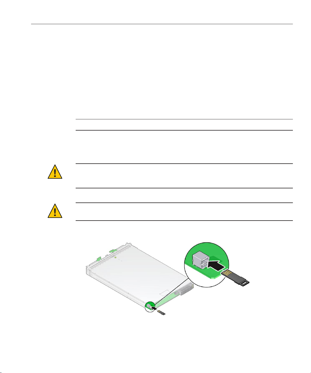
Prepare the servermodule for operation.
5
See
“Returning Sun Blade X3-2B to Operation ” on page 101.
Servicing USB Flash Drives (CRU)
Next Steps
“Install USB Flash Drives” on page 69
▼
Install USB Flash Drives
Prepare the servermodule for service.
1
See
“Preparing the Sun Blade X3-2B for Service ” on page 27.
Note – You do not have to remove the server module top cover to access the rear USB ports.
Locate the correct rear USB port P0 (OracleSystem Assistant) or P1.
2
Push the USB ash drive into port 0 or 1.
3
Caution – Component damage or data loss. USB ash drives must t inside the rear of the
motherboard. Installing a longer USB drive on the rear port might damage the blade when
inserted into the chassis. Drives can be no larger than 7.5 mm wide and 43 .0 mm deep.
Caution – Component damage. Ensure the USB ash drive contacts are in the upward-facing
position.
Prepare the servermodule for operation.
4
See
“Returning Sun Blade X3-2B to Operation ” on page 101.
69
Page 70

Servicing a Fabric Expansion Module (CRU)
Caution – Component damage or data loss. Flash drives extend past the rear of the blade. Handle
the blade with care.
Verify component information.
5
Use the Oracle ILOM web interface or CLI.
Refer to the
Oracle Integrated Lights Out Manager (ILOM) 3.1 Documentation Collection
(http://www.oracle.com/pls/topic/lookup?ctx=ilom31)
Servicing a Fabric Expansion Module (CRU)
Note – This component is a customer-replaceable unit (CRU).
The fabric expansion module (FEM) is available in either single-width or double-width form
factor.
.
Figure Legend
1 FEM double-width form factor. 2 FEMsingle-width form factor. Install in FEM 0.
Use these procedures to remove and install a fabric expansion module (FEM) card option:
■
“Remove a FEM” on page 71
■
“Install a FEM” on page 71
Sun Blade X3-2B (formerly Sun Blade X6270 M3) Service Manual • May,201470
Page 71

Servicing a Fabric Expansion Module (CRU)
▼
Remove a FEM
Prepare the servermodule for service.
1
See
“Preparing the Sun Blade X3-2B for Service ” on page 27.
Insert a ller panel into the empty server slot to reduce the possibility of a system shut down.
2
Pull the existing FEM card up and out of the motherboard.
3
Next Steps
“Install a FEM” on page 71
▼
Install a FEM
Prepare the servermodule for service.
1
See
“Preparing the Sun Blade X3-2B for Service ” on page 27.
Remove the existing FEM card, as required.
2
See
“Remove a FEM” on page 71.
Slide the FEM card at an angle into the support bracket.
3
Note – Always install a single-width form factor FEM in FEM 0.
71
Page 72

Servicing a RAID Expansion Module (CRU)
Press the FEM card carefully into the connector.
4
Prepare the servermodule for operation.
5
See
“Returning Sun Blade X3-2B to Operation ” on page 101.
Servicing a RAID Expansion Module (CRU)
Note – This component is a customer-replaceable unit (CRU).
The RAID expansion module (REM), if ordered, might not arrive installed on the Sun Blade
X3-2B. In some cases, this option is shipped separately for customer installation. The REM
enables the RAID functionality for SAS drives.
Refer to
Administration Guide
Sun Blade X3-2B (formerly Sun Blade X6270 M3) Service Manual • May,201472
“Conguring RAID” in Sun Blade X3-2B (formerly Sun Blade X6270 M3)
for additional information.
Page 73

BeforeYou Begin
Servicing a RAID Expansion Module (CRU)
A REM Storage Drive cable kit is required when you want a Sun Blade X3-2B to communicate
with the Sun Blade Storage Module M2 across the Sun Blade 6000 midplane. See
“Servicing
Cables (CRU)” on page 77
Note – When adding a REM to a server, you must install one or more storage drives (hard disk or
solid state drive) in the server disk slots 0 through 3.
Use these procedures to service a REM card option:
■
“Remove a REM Card” on page 73
■
“Install a REM Card” on page 74
■
“Replace a REM Battery on the REM Card” on page 76
▼
Remove a REM Card
Caution – Data loss. Back up your data to an external site before proceeding. The following steps
will remove all data from the system.
Next Steps
Prepare the servermodule for service.
1
See
“Preparing the Sun Blade X3-2B for Service ” on page 27.
Open the REM latch.
2
Locate the REM support bracket on the motherboard,and pull the REM card out at an angle
3
away from the support bracket [1].
Pull the REM card carefully out of the connector [2].
4
“Install a REM Card” on page 74
73
Page 74

Servicing a RAID Expansion Module (CRU)
▼
Install a REM Card
Use this procedure with the REM removal procedure to replace an existing REM, or use this
procedure for rst-time installation of a REM card in the server.
BeforeYou Begin
Caution – Data loss. Back up your data to an external site before proceeding. The following steps
will remove all data from the system.
1
Prepare the servermodule for service.
“Preparing the Sun Blade X3-2B for Service ” on page 27.
See
2
Insert a ller panel into the empty server slot to reduce the possibility of a system shut down.
“Insert Server Module Filler Panels” on page 41.
See
3
If you arereplacing a REM card, remove the existing card.
“Remove a REM Card” on page 73.
See
If you areperforming a rst-time REM card installation, connect the REM storage drive cable to
4
the motherboard.
“Install the REM Storage Drive Cable” on page 78.
See
Note – The REM storage drive cable must be installed when the system is using a REM.
Locate the REM support bracket on the motherboard.
5
For more information, see
Close the REM handle [1].
6
Slide the REM card under the anges on the support bracket.
7
“Replaceable Server Module Components” on page 24.
The anges are on the support bracket opposite the REM handle.
Sun Blade X3-2B (formerly Sun Blade X6270 M3) Service Manual • May,201474
Page 75

Servicing a RAID Expansion Module (CRU)
Carefully align the connector on the underside of the REM card with the connector on the
8
motherboard.
To install the REM card,gently push down on the connector end of the card until the card is fully
9
seated under the REM card retaining spring.
Caution – Component damage. Excessive downward force is not required. When properly
aligned the connectors mate with minimum downward pressure. If not, realign the connectors
slightly and try again. Do not apply excessive force.
An audible click occurs when the spring secures the card.
If this is a rst-time installation of a REM cardin the server module, perform the following
10
sub-steps.
Perform the following sub–steps only if the new disk does not have an operating system, or any
data. Skip this step if preloaded software resides on the storage drives.
a. Restore the data from backups.
b. Install an operating system.
Operating System Link
Linux Sun Blade X3-2B (formerly Sun Blade X6270 M3) Installation Guide for Linux
Operating Systems
Solaris Sun Blade X3-2B (formerly Sun Blade X6270 M3) Installation Guide for the Oracle
Solaris Operating System
Windows Sun Blade X3-2B (formerly Sun Blade X6270 M3) Installation Guide for Windows
Operating Systems
VM Sun Blade X3-2B (formerly Sun Blade X6270 M3) Installation Guide for ESX
Software
Oracle VM Sun Blade X3-2B (formerly Sun Blade X6270 M3) Installation Guide for Oracle VM
Server
Prepare the servermodule for operation.
11
See
“Returning Sun Blade X3-2B to Operation ” on page 101.
75
Page 76
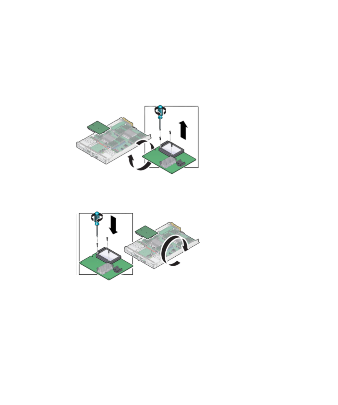
Servicing a RAID Expansion Module (CRU)
▼
Replace a REM Battery on the REM Card
BeforeYou Begin
This task requires a #00 Phillips screwdriver.
Remove the REM card.
1
“Remove a REM Card” on page 73.
See
Remove and retain the three screwssecuring the REM battery to the card.
2
3
Remove the REM battery from the REM card.
Attach the new battery to the REM card using the three screws.
4
5
Attach any required battery cables and install the REM card in the servermodule.
“Install a REM Card” on page 74.
See
Sun Blade X3-2B (formerly Sun Blade X6270 M3) Service Manual • May,201476
Page 77

Servicing Cables (CRU)
This section contains procedures for removing and installing the REM storage drive cable:
■
“Remove the REM Storage Drive Cable” on page 77
■
“Install the REM Storage Drive Cable” on page 78
▼
Remove the REM Storage Drive Cable
Use this procedure when replacing a REM storage drive cable.
1
Prepare the servermodule for service.
“Preparing the Sun Blade X3-2B for Service ” on page 27.
See
Remove the REM card.
2
“Remove a REM Card” on page 73.
See
Make note of the cable's route through the server.
3
The replacement cable must be routed through the server following the same path.
Disconnect the ribbon cable from the connector at the frontmotherboard.
4
Servicing Cables (CRU)
Next Steps
Disconnect the ribbon cable from the connector at the rearof the motherboard.
5
Remove the cable from the server.
6
“Install the REM Storage Drive Cable” on page 78
77
Page 78

Servicing Cables (CRU)
▼
Install the REM Storage Drive Cable
Use this procedure with the REM storage drive cable removal procedure to replace an existing
cable, or use this procedure for rst-time installation of a REM card in the server.
Prepare the servermodule for service.
1
See
“Preparing the Sun Blade X3-2B for Service ” on page 27.
If you arereplacing an existing REM Storage Drive cable, do the following:
2
a.
“Remove a REM Card”on page 73
b. “Remove the REM Storage DriveCable”on page 77
Connect the new REM StorageDrive cable to the connector at the front of the motherboard.
3
Caution – Do not insert the REM Storage Drive cable into the connector near CPU 1.
Carefully route and dress the cable through the server toward the rear connector as shown in
4
the illustration below:
The cable must be routed exactly as shown in the illustration.
Sun Blade X3-2B (formerly Sun Blade X6270 M3) Service Manual • May,201478
Page 79
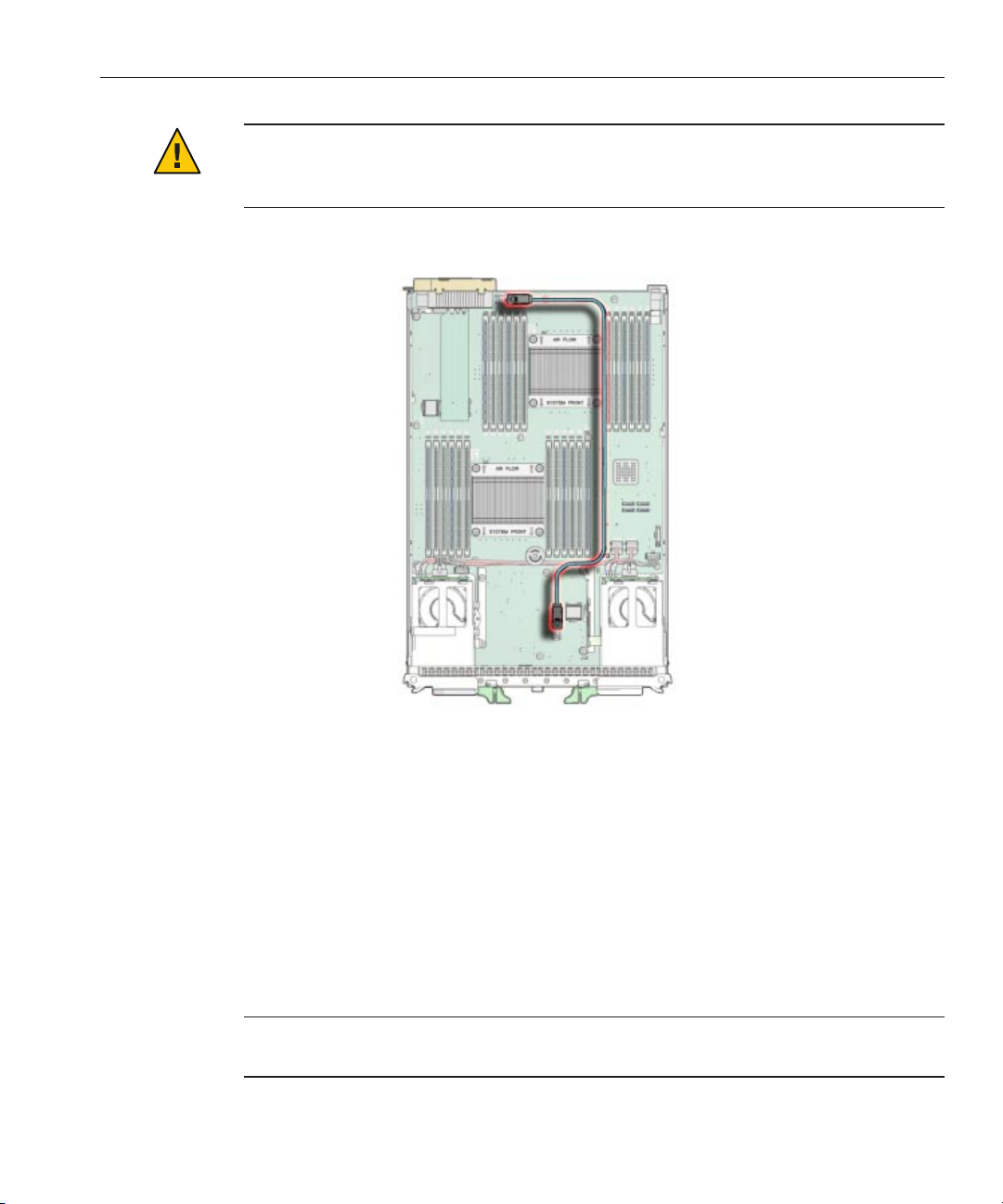
Servicing a Processor and Heat Sink Assembly (FRU)
Caution – Component damage. Do not deviate from the cable route. Ensure that the cable does
not protrude above the server enclosure side walls and contact or interfere with the server top
cover.
Connect the cable to the connector at the rear of the motherboard.
5
Install the REM card.
6
See
“Install a REM Card” on page 74.
Prepare the servermodule for operation.
7
See
“Returning Sun Blade X3-2B to Operation ” on page 101.
Servicing a Processor and Heat Sink Assembly (FRU)
Note – This component is a eld-replaceable unit (FRU). A part designated as a FRU must be
replaced by an Oracle-qualied service technician.
79
Page 80

Processor FaultRemind Circuit
When replacing a processor, ensure that the replacement processor matches the speed of the
other processor on the motherboard, and ensure that you use the replacement tool that is
packaged with the new processor.
Tip – To watch a video that shows how to remove and install a processor using the replacement
tool, see
Use these procedures to remove and install processor and heat sink assemblies:
■
■
■
■
■
■
■
Processor Fault Remind Circuit
The following illustrations shows the components and locations of the server module fault
remind circuit. Use the fault remind circuit to identify a failed processor.
CPU Replacement Overview Video.
“Processor Fault Remind Circuit” on page 80
“Identify a Faulty Processor” on page 82
“Remove a Processor Heat Sink” on page 83
“Remove a Processor” on page 84
“Install a Processor” on page 87
“Install a Processor Heat Sink” on page 90
“Clear Server Module Processor Faults” on page 92
The following topics describe the components of the Fault Remind circuitry.
Sun Blade X3-2B (formerly Sun Blade X6270 M3) Service Manual • May,201480
Page 81

FaultRemind Button and Charge Status LED
Processor FaultRemind Circuit
Note – Do not press the white Clear CMOS Button (SW1801).
The blue Fault Remind button (SW3001) is located on the motherboard next to the Charge
Status LED (CR3002). The Charge Status LED indicates the usability of the processor test
circuit. When the Fault Remind button is pressed, the Charge Status LED, lights green to
indicate that there is sucient voltage present in the fault remind circuit to activate the fault
LEDs. Processor Fault LEDs identify a processor in a fault state.
Note – Press the fault remind circuitry within 15 minutes of removing the server from the
chassis. If the green Charge Status LED fails to light when you press the Fault Remind button, it
is likely that the fault remind circuit has lost its charge.
Processor Fault LED
81
Page 82

Processor FaultRemind Circuit
The Processor Fault LEDs are located on the server module motherboard next to each
processor. The amber LEDs light up when the Fault Remind button is pressed and a processor
fault condition exists.
Related Information
“Using the DIMM and Processor Test Circuit ” on page 108
▼
Identify a Faulty Processor
Prepare the servermodule for service.
1
“Preparing the Sun Blade X3-2B for Service ” on page 27.
See
Caution – Component damage. This procedure requires that you handle components that are
sensitive to static discharge. This sensitivity can cause the component to fail. To avoid damage,
ensure that you follow electrostatic discharge safety measures and antistatic practices. See
“Performing ESD and Antistatic Prevention Measures” on page 33.
Press and hold the Fault Remind button on the motherboard to illuminate a processor FaultLED
2
(for more information, see “Processor Fault Remind Circuit”on page 80).
A failed processor is identied by the amber processor Fault LED, as indicated in the following
table.
Sun Blade X3-2B (formerly Sun Blade X6270 M3) Service Manual • May,201482
Page 83

LED State Processor Status
O Operating properly.
On (amber) Faulty and should be replaced.
Processor FaultRemind Circuit
Next Steps
BeforeYou Begin
“Remove a Processor Heat Sink” on page 83
▼
Remove a Processor Heat Sink
To replace a processor, you must rst remove the processor heat sink. The heat sink sits on top
of the processor and is secured to the motherboard by four screws. Once removed, retain the
heat sink for reuse.
Tip – To watch a video that shows how to remove and install a processor using the replacement
tool, see
Caution – Component damage. Handle processor socket pins with extreme care. Processor and
CPU Replacement Overview Video.
socket pins are very fragile. A light touch can bend the processor socket pins and damage the
board beyond repair.
■
“Preparing the Sun Blade X3-2B for Service ” on page 27
■
“Identify a Faulty Processor” on page 82
■
A number 2 Phillips screwdriver is required for this procedure.
Gently press down on the top of the heat sink to counteract the pressure of the captive
1
spring-loaded screws that secure the heat sink to the motherboard.
Using a No.2 Phillips screwdriver, alternately loosen the four screws in the heat sink.
2
Turn each screw one and one half turns until they are fully disengaged.
83
Page 84

Processor FaultRemind Circuit
To separate the heat sink from the top of the processor, gently wiggle the heat sink left and
3
right, while pulling upward.
A thin layer of thermal compound separates the heat sink and the processor. This compound
also acts as an adhesive.
Note – Do not allow the thermal compound to contaminate the work space or other
components.
Place the heat sink upside down on a at surface.
4
Next Steps
BeforeYou Begin
“Remove a Processor” on page 84
▼
Remove a Processor
Tip – To watch a video that shows how to remove and install a processor using the replacement
tool, see
Caution – Component damage. Handle processor socket pins with extreme care. Processor and
CPU Replacement Overview Video.
socket pins are very fragile. A light touch can bend the processor socket pins and damage the
board beyond repair.
■
See “Remove a Processor Heat Sink” on page 83.
■
CPU Replacement Overview Video
■
Processor replacement tool model LGA2011 (color code: green) is required for this
procedure.
Caution – Component damage. Use the correct processor replacement tool. Attempting to
replace the processor using the incorrect tool could result in irreparable damage the
processor or the motherboard.
Sun Blade X3-2B (formerly Sun Blade X6270 M3) Service Manual • May,201484
Page 85
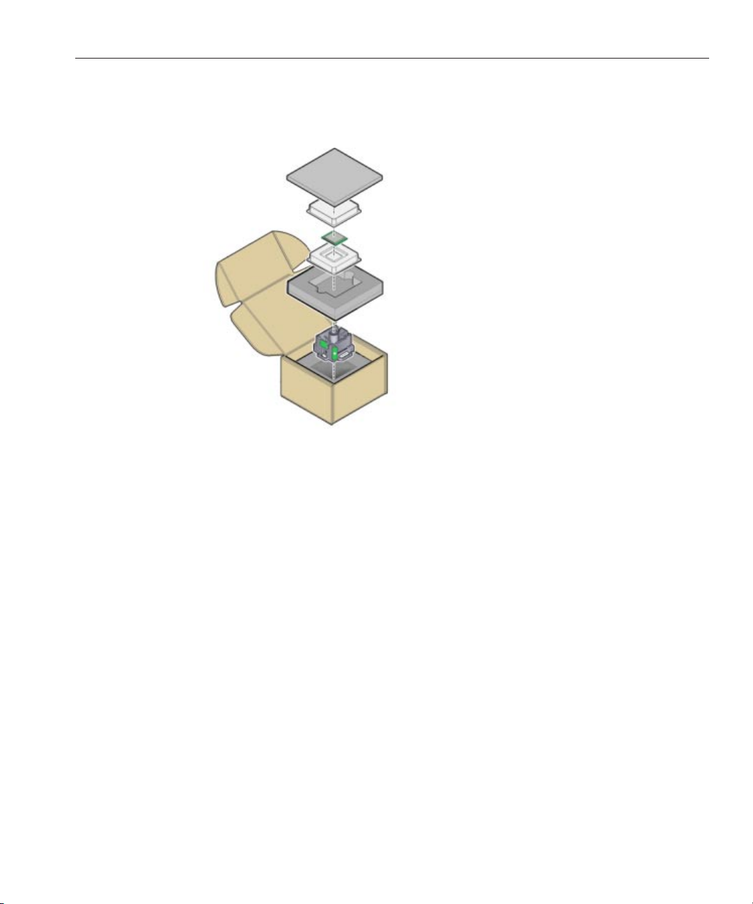
Processor FaultRemind Circuit
Unpack the processor and processor removal/insertion tool from the replacement processor
1
packaging, as required.
Leave the processor in the anti-static tray until it is ready to be installed.
Release the two processor pressure frame retaining levers on the servermodule motherboard
2
[1].
a. Disengage the processor release lever on the right side of the processor socket (viewing the
server from the front) by pushing down and moving it to the side away from the processor,
and then rotating the lever upward.
b. Disengage the processor release lever on the left side of the processor socket (viewing the
server from the front) by pushing down and moving it to the side away from the processor,
and then rotating the lever upward.
85
Page 86

Processor FaultRemind Circuit
Lift the processor pressure frame up to the fully open position [2].
3
Push the removal/insertion tool button [1].
4
Place the removal/insertion tool on top of the processor [2].
5
Properly position the tool over the processor socket and lower it into place over the processor
socket. Ensure that the tool and processor key corners are aligned. To properly position the tool
over the processor socket, rotate the tool until the green triangle on the side of the tool is facing
the front of the server and it is over the left side of the processor socket when viewing the server
from the front.
Click the tab on the removal/insertion tool to secure the tool to the processor [3].
6
Press the release lever on the tool to release the center button and engage the processor. An
audible click indicates that the processor is engaged.
Lift the processor out of the socket while it is still attached to the removal/insertion tool [4].
7
Sun Blade X3-2B (formerly Sun Blade X6270 M3) Service Manual • May,201486
Page 87

Processor FaultRemind Circuit
Turnthe tool upside down and verify that it contains the processor[5].
8
9
Hold the processor by its edges and press the center button on the tool to releasethe processor
[5].
10
Carefully lift it out of the tool and place it with its circuit side down (the installed orientation) on
an antistatic mat [6].
Carefully clean the thermal compound o the top of the processor.
11
Place the removedprocessor into an antistatic container.
12
Next Steps
BeforeYou Begin
“Install a Processor” on page 87
▼
Install a Processor
Tip – To watch a video that shows how to remove and install a processor using the replacement
tool, see
■
■
■
CPU Replacement Overview Video.
CPU Replacement Overview Video
“Preparing the Sun Blade X3-2B for Service ” on page 27
“Remove a Processor Heat Sink” on page 83
87
Page 88

Processor FaultRemind Circuit
■
Unpack the replacement processor and place it on an anti-static mat.
1
2
Ensure that the two processor socket release levers arein the fully open position [1].
“Remove a Processor” on page 84
Ensure that the processor pressure frame is in the fully open position [2].
3
Press the button in the center of the tool to the down position [1].
4
Turnthe tool upside down, grasp the processor by its edges and place the processor (circuit side
5
up) in the tool [2].
Ensure that the triangle on the corner of the processor aligns with the triangle on the side of the
processor removal/replacement tool [2].
Sun Blade X3-2B (formerly Sun Blade X6270 M3) Service Manual • May,201488
Page 89

Processor FaultRemind Circuit
Press the tool release lever to release the center button and secure the processor in the tool.
6
An audible click indicates that the processor is locked in place.
Ensure that the processor is secure in the tool before rotating the tool.
7
Rotate the tool,so the processor faces downward.
8
Properly position the tool over the processor socket and lower it into place [4].
9
Ensure that the notches on the sides of the processor align with the keys on the socket, and the
green triangle on the side of the tool is aligned with the front left corner of the processor socket
(when viewing from the front of the server).
Press the center button to releasethe processor [5].
10
Caution – Component damage. Do not press down on the processor. Irreparable damage to the
processor or motherboard might occur from excessive downward pressure. Do not forcibly seat
the processor into the socket. Excessive downward pressure might damage the socket pins.
Remove the processor removal/replacementtool [6].
11
89
Page 90

Processor FaultRemind Circuit
Visually check the alignment of the processor in the socket [7].
12
When properly aligned, the processor sits at in the processor socket and has minimal
side-to-side movement.
Close the processor pressure frame cover[1].
13
Lower the rst retaining lever and secure it under the retaining clip [2].
14
Lower the second retaining lever and secure it under the retaining clip [2].
15
This action secures the processor in the socket.
Next Steps
BeforeYou Begin
“Install a Processor Heat Sink” on page 90
▼
Install a Processor Heat Sink
The replacement processor is not shipped with a heat sink. Reuse the original processor heat
sink.
■
“Remove a Processor” on page 84
■
“Install a Processor” on page 87
Clean the heat sink:
1
■
Remove any dust or debris that might be lodged in the heat sink ns.
Sun Blade X3-2B (formerly Sun Blade X6270 M3) Service Manual • May,201490
Page 91

Processor FaultRemind Circuit
■
Use an alcohol pad to completely clean all thermal compound from the underside of the
heat sink.
2
Use the syringe (supplied with the new or replacement processor) to apply approximately 0.1 ml
of thermal compound as a single dollop to the center of the top of the processor.
Note – Do not distribute or spread the compound; the pressure applied when attaching the heat
sink performs this action.
Position the heat sink over the processor, aligning it with the threaded mounting posts.
3
Orient the heat sink so that the screws line up with the mounting posts. The processor heat sink
is not symmetrical.
Caution – Component damage. When handling the heat sink, do not to transfer the compound
to other server components.
Carefully lower the heat sink onto the processor takingcare to reducethe amount of movement
4
it makes after initial contactwith the layer of thermal compound on topof the processor.
91
Page 92

Processor FaultRemind Circuit
Caution – Over-temperature condition. Avoid moving the heat sink after it has contacted the top
of the processor. Too much movement could spread the layer of thermal compound, causing
voids in the distribution and leading to ineective heat dissipation and component damage.
Use a No.2 Phillips screwdriverto alternately tighten each Phillips screw one-half turn until fully
5
seated.
6
Prepare the servermodule for operation.
See
“Returning Sun Blade X3-2B to Operation ” on page 101.
Next Steps
Update the BIOS and ILOM rmware.
7
Refer to the
Sun Blade X3-2B (formerly Sun Blade X6270 M3) Administration Guide and
“Setting Up Software and Firmware” in Sun Blade X3-2B (formerly Sun Blade X6270 M3)
Installation Guide
■
“Clear Server Module Processor Faults” on page 92
▼
Clear Server Module Processor Faults
.
Use Oracle ILOM command-line interface (CLI) commands to view and clear server module
faults.
Log in to the serveras root, using Oracle ILOM CLI.
1
“Access Oracle ILOM Using CLI” in Sun Blade X3-2B (formerly Sun Blade X6270 M3)
See
Administration Guide
To list all known faults on the system, type:
2
.
-> show /SP/faultmgmt
Sun Blade X3-2B (formerly Sun Blade X6270 M3) Service Manual • May,201492
Page 93

The server lists all known faults, for example:
-> show /SP/faultmgmt
Targets: 0 (/SYS/MB/P0)
Properties:
Commands:
cd
show
3
To clear the fault, type:
-> set /SYS/MB/P0 clear_fault_action=true
For example:
-> set /SYS/MB/P0 clear_fault_action=true
Are you sure you want to clear /SYS/MB/P0 (y/n)? y
Set ’clear_fault_action’ to ’true’
4
Close the Oracle ILOM session.
Servicing the Motherboard Assembly (FRU)
■
See Also
Oracle Integrated Lights Out Manager (ILOM) 3.1 Documentation Collection
(http://www.oracle.com/pls/topic/lookup?ctx=ilom31)
Servicing the Motherboard Assembly (FRU)
Note – This component is a eld-replaceable unit (FRU). A part designated as a FRU must be
replaced by an Oracle-qualied service technician.
The motherboard assembly includes the motherboard, the disk backplane and the server
module enclosure. The motherboard and the disk backplane are shipped installed in the
enclosure. Do not remove the motherboard or the disk backplane from the enclosure. If either
of these components fails, replace the entire motherboard assembly.
To replace the motherboard assembly, transfer all reusable components from the failed
assembly to the replacement assembly and update the FRUID using the following procedures:
■
“Remove and Install a Processor Cover Plate” on page 94
■
“Motherboard Assembly Replacement” on page 97
■
“Update FRUID (Service Only)” on page 98
93
Page 94

Servicing the Motherboard Assembly (FRU)
▼
Remove and Install a Processor Cover Plate
Cover plates are plastic inserts that attach to the processor load plate and protect the pins of an
unoccupied psocket. Cover plates are installed on replacement motherboards and need to be
removed before installing processors and heatsinks. When removing or installing processor
cover plates, ensure that the pins in the processor socket are not damaged.
Ensure proper ESD protection.
1
Release the two processor pressure frame retaining levers on the processor socket [1].
2
Caution – Component damage. The pins in the processor socket are fragile. Opening the
pressure frame and the load plate exposes the pins. Do not touch or damage the processor
socket pins.
a. Disengage the processor release lever on the right side of the processor socket (viewing the
server from the front) by pushing down and moving it to the side away from the processor,
and then rotating the lever upward.
b. Disengage the processor release lever on the left side of the processor socket (viewing the
server from the front) by pushing down and moving it to the side away from the processor,
and then rotating the lever upward.
Sun Blade X3-2B (formerly Sun Blade X6270 M3) Service Manual • May,201494
Page 95

Lift the processor pressure frame up to the fully open position [2].
3
With the pressure frame in the open position, do one of the following:
4
■
To remove a cover plate, gently push on the underside of the plate.
The plate is tted into the pressure frame. Pushing on the underside of the plate causes the it
to pop out of the frame.
Servicing the Motherboard Assembly (FRU)
95
Page 96

Servicing the Motherboard Assembly (FRU)
■
To install a cover plate, align the plate with the topside of the pressure frame and gently
push it into the frame until it locks in place.
The cover plate is notched to t the pressure frame and must align correctly.
Next Steps
5
Close and lock the load plate.
■
“Motherboard Assembly Replacement” on page 97
Sun Blade X3-2B (formerly Sun Blade X6270 M3) Service Manual • May,201496
Page 97

Servicing the Motherboard Assembly (FRU)
▼
Motherboard Assembly Replacement
Use this procedure to replace the motherboard assembly if the motherboard or the disk
backplane fails.
Note – If you replace a motherboard or a service processor and an incompatibility arises between
the hardware revision of the component and the rmware version of either the SP or the BIOS,
the best practice is to maintain compatibility with the SP rmware. Therefore, update or
downgrade the system rmware package to the version compatible with the SP.
BeforeYou Begin
For the location of components, see “Replaceable Server Module Components” on page 24.
Before removing the server module, back up the SP conguration.
1
Refer to the
Prepare the servermodule for service.
2
See
“Preparing the Sun Blade X3-2B for Service ” on page 27.
Insert a blade ller panel into the empty slot.
3
See
“Insert Server Module Filler Panels” on page 41.
Remove reusable components from the old server module motherboard.
4
Caution – Data loss and over-temperature condition. Label components before removal to
Sun Blade X3-2B (formerly Sun Blade X6270 M3) Administration Guide.
ensure components are returned to original slots.
a. Perform the following component removalprocedures,as required:
■
“Remove a Storage Drive” on page 51
Note the storage drive positions (0, 1, 2, 3).
■
“Remove DIMMs” on page 62
Note the DIMM positions.
■
“Remove a Processor Heat Sink” on page 83
Note the processor positions (0 and 1).
■
“Remove a Processor” on page 84
■
“Remove USB Flash Drives” on page 68
Note the ash drive positions (0 and 1).
■
“Remove a REM Card” on page 73
■
“Remove a FEM” on page 71
97
Page 98

Servicing the Motherboard Assembly (FRU)
b. Perform the following ller removal procedures, as required:
■
“Remove Storage Drive Filler Panels” on page 54
■
“Remove Optional DIMM Filler Panels” on page 65
Install the components on the replacement motherboard assembly.
5
a. Perform the following component installation procedures, as required:
■
“Replace a Storage Drive” on page 53
■
“Remove and Install a Processor Cover Plate” on page 94
■
“Install a Processor” on page 87
■
“Install DIMMs” on page 63
■
“Install a REM Card” on page 74
■
“Install a FEM” on page 71
■
“Install USB Flash Drives” on page 69
b. Perform the following ller installation procedures, as required:
■
“Insert Storage Drive Filler Panels” on page 55
■
“Install Optional DIMM Filler Panels” on page 65
Prepare the servermodule for operation.
6
“Returning Sun Blade X3-2B to Operation ” on page 101.
See
Note – Do not power on the server.
Update the FRUID/serial number on the new motherboard.
7
“Update FRUID (Service Only)” on page 98.
See
Restore SP conguration.
8
▼
Update FRUID (Service Only)
Note – This procedure requires access to Escalation mode.
Use the setpsnc command to program the previous serial number to the new FRUID.
Place the server module in standby power mode.
1
“Graceful Power O Using the Power Button” on page 29.
See
Sun Blade X3-2B (formerly Sun Blade X6270 M3) Service Manual • May,201498
Page 99

To restore FRUID information, log in to Escalation mode.
2
The Escalation mode command-line prompt appears: #
3
Note the previous server module serial number.
Poweron the server module.
4
“Apply Full Power ” on page 104.
See
Servicing the Motherboard Assembly (FRU)
99
Page 100

100
 Loading...