

Page 1

Sun Blade T6340 Server Module
Installation and Administration Guide
Part No. 820-3900-12
April 2010, Revision A
Page 2

Copyright ©2008, 2010, Oracle and/or itsaffiliates. All rights reserved.
This software andrelated documentation are provided under a license agreement containing restrictions onuse and disclosure and are
protected by intellectual propertylaws. Except as expressly permitted in yourlicense agreement or allowed by law, youmay not use, copy,
reproduce, translate, broadcast, modify, license, transmit, distribute, exhibit, perform, publish, or display any part, in any form, or by any
means. Reverseengineering, disassembly,or decompilation of this software, unlessrequired bylaw for interoperability, isprohibited.
The informationcontained herein is subject to change without notice and is not warrantedto be error-free. If you find any errors, please report
them tous in writing.
If thisis software or related software documentation that is delivered tothe U.S. Government or anyonelicensing it on behalf ofthe U.S.
Government, thefollowing notice is applicable:
U.S. GOVERNMENTRIGHTS. Programs, software, databases, and related documentation and technicaldata delivered to U.S. Government
customers are "commercial computersoftware" or "commercial technical data" pursuant tothe applicable Federal Acquisition Regulation and
agency-specific supplementalregulations. As such, the use, duplication, disclosure,modification, and adaptation shall be subject to the
restrictions and license terms set forth in the applicable Government contract, and, to theextent applicable by the termsof the Government
contract, theadditional rights set forth inFAR 52.227-19, Commercial Computer Software License (December 2007).Oracle USA, Inc., 500
Oracle Parkway, RedwoodCity, CA94065.
This software orhardware isdeveloped for general use ina variety of information management applications. It is not developed or intendedfor
use inany inherently dangerous applications, including applications whichmay createa risk of personal injury. Ifyou use this software or
hardware in dangerous applications, then you shall be responsible to take all appropriatefail-safe, backup, redundancy, andother measures to
ensure the safe use. Oracle Corporation and its affiliatesdisclaim any liability for any damages caused by use of this softwareor hardware in
dangerous applications.
Oracle andJava are registered trademarks of Oracle and/or its affiliates. Othernames may be trademarks oftheir respective owners.
AMD, Opteron, theAMD logo, and the AMDOpteron logoare trademarks or registeredtrademarks of Advanced Micro Devices. Intel andIntel
Xeon are trademarksor registeredtrademarks of Intel Corporation. AllSPARCtrademarks areused under license and are trademarksor
registered trademarks of SPARC International, Inc. UNIX is a registered trademarklicensed throughX/Open Company, Ltd.
This software or hardware and documentation may provide access to or information on content, products, and services from third parties.
Oracle Corporationand its affiliates are not responsible for and expressly disclaim all warranties ofany kind with respect to third-party content,
products, and services. Oracle Corporation and its affiliates will not be responsible for any loss, costs, or damages incurred due to your access
to or use of third-party content, products, or services.
Copyright ©2008, 2010, Oracle et/ou sesaffiliés. Tous droits réservés.
Ce logicielet la documentation qui l’accompagnesont protégés par les lois sur lapropriété intellectuelle. Ils sont concédés sous licence et
soumis àdes restrictions d’utilisation et de divulgation. Sauf disposition de votre contrat de licence ou de la loi, vous ne pouvez pas copier,
reproduire, traduire, diffuser, modifier, breveter, transmettre, distribuer, exposer, exécuter,publier ou afficher le logiciel, même partiellement,
sous quelqueforme et par quelque procédé quece soit. Par ailleurs, ilest interditde procéder à toute ingénierie inverse du logiciel, de le
désassembler oude le décompiler, exceptéà des fins d’interopérabilité avec des logicielstiers ou tel que prescrit par la loi.
Les informationsfournies dans ce document sontsusceptibles de modification sans préavis.Par ailleurs, Oracle Corporation negarantit pas
qu’elles soientexemptes d’erreurs et vous invite, le cas échéant, à lui en faire partpar écrit.
Si celogiciel, ou la documentation quil’accompagne, est concédé sous licenceau Gouvernement des Etats-Unis, ouà toute entité qui délivre la
licence dece logiciel ou l’utilise pourle compte du Gouvernement desEtats-Unis, la notice suivante s’applique:
U.S. GOVERNMENT RIGHTS. Programs, software, databases, and related documentation and technical data delivered to U.S. Government
customers are "commercial computer software" or "commercial technical data" pursuant to the applicable Federal Acquisition Regulation and
agency-specific supplemental regulations. As such, the use, duplication, disclosure, modification, and adaptation shall be subject to the
restrictions and license terms set forth in the applicable Government contract, and, to the extent applicable by the terms of the Government
contract, the additional rights set forth in FAR 52.227-19, Commercial Computer Software License (December 2007). Oracle America, Inc., 500
Oracle Parkway, Redwood City, CA 94065.
Ce logicielou matériel a été développépour un usage général dansle cadred’applications de gestion des informations.Ce logiciel ou matériel
n’est pasconçu ni n’est destiné àêtre utilisé dans des applications à risque,notamment dans des applications pouvantcauser des dommages
corporels. Si vous utilisez ce logiciel ou matériel dans le cadre d’applications dangereuses, il est devotre responsabilitéde prendre toutesles
mesures de secours, de sauvegarde, de redondance et autres mesures nécessaires à son utilisation dans des conditions optimales de sécurité.
Oracle Corporationet ses affiliés déclinent toute responsabilité quantaux dommages causés par l’utilisation de ce logiciel ou matériel pour ce
type d’applications.
Oracle etJava sont des marques déposées d’Oracle Corporation et/ou de ses affiliés.Tout autre nom mentionné peut correspondre à des
marques appartenant à d’autrespropriétaires qu’Oracle.
AMD, Opteron, lelogo AMD et le logoAMD Opteron sont des marques ou des marques déposéesd’Advanced Micro Devices. Intel et Intel
Xeon sontdes marques ou des marques déposées d’IntelCorporation. Toutes les marques SPARC sont utiliséessous licence et sont desmarques
ou desmarques déposées de SPARC International, Inc.UNIX est une marque déposée concédée souslicence par X/Open Company, Ltd.
Ce logicielou matériel et la documentationqui l’accompagne peuvent fournir desinformations ou des liens donnantaccès à des contenus, des
produits et des services émanant de tiers. Oracle Corporation et ses affiliés déclinent toute responsabilité ougarantie expresse quant aux
contenus, produits ouservices émanant de tiers. Enaucun cas, Oracle Corporation etses affiliés ne sauraient être tenus pour responsables des
pertes subies,des coûts occasionnés ou desdommages causés par l’accès àdes contenus, produits ou services tiers, ouà leur utilisation.
Page 3

Contents
Using This Document vii
1. Before You Begin the Installation 1
Hardware Overview 1
Physical Specifications 3
Environmental Requirements 3
Front Panel Features 4
Preinstalled Software 5
Managing the Server Module With ILOM 5
Service Processors 5
Chassis Management Module 6
ILOM on the CMM and Server Module SP 6
Establishing Communication With ILOM 6
Attaching a Serial Console to the Chassis Management Module 6
Attaching a Serial Console to the Server Module 7
2. Installation and Configuration 9
Handling the Server Module 9
Installing the Server Module into the Chassis 10
▼ To Insert the Server Module 10
iii
Page 4

Connecting and Configuring the Server Module 12
Connecting to the Server Module 13
Connecting Through the Chassis CMM Ethernet Port 13
Connecting to the Server Module SP Through the Chassis CMM Serial
Connector 16
Connecting to the Server Module SP Using a Dongle Cable 19
▼ To Connect a Storage Device to the Dongle Cable 20
Configuring and Viewing the IP Address for a Server Module SP 20
Configuring and Viewing the IP Address for a Server Module SP Through
the CMM 20
▼ To View or Configure the IP Address for the Server Module SP When
Assigned by DHCP — Through the CMM 21
▼ To View or Configure the IP Address for the Server Module SP Using
Static IP Addresses — Through the CMM 22
Configuring and Viewing the IP Address for a Server Module SP Through the
UCP 25
▼ To View or Configure the IP Address for the Server Module SP When
Assigned by DHCP — Through the UCP 25
▼ To View or Configure the IP Address for the Server Module SP Using
Static IP Addresses — Through the UCP and Dongle Cable 26
Connecting a Remote Console or Remote KVMS 27
Switching Between the ILOM Prompt and the System Console 27
▼ To Switch Between the ILOM Prompt and the System Console 28
Connecting to the Server Module With a Local Graphics Monitor or Local
KVMS 29
▼ To Access the System Console Through a Local Graphics Monitor 29
Changing the ILOM Password 30
Powering On the Host 31
▼ To Power on the Server Module Manually 32
▼ To Shut Down Main Power Mode 32
Installing the Solaris Operating System on a Hard Drive 32
iv Sun Blade T6340 Server Module Installation and Administration Guide • April 2010
Page 5

JumpStart Server Installation 33
JumpStart Server Configuration 33
3. Managing Disk Volumes 35
OS Patch Requirements 35
Disk Volumes 35
RAID Technology 36
Integrated Stripe Volumes (RAID 0) 36
Integrated Mirror Volumes (RAID 1) 37
Hardware Raid Operations 38
Physical Disk Slot Numbers, Physical Device Names, and Logical Device
Names for Non-RAID Disks 38
▼ To Create a Hardware Mirrored Volume 39
▼ To Create a Hardware Mirrored Volume of the Default Boot Device 42
▼ To Create a Hardware Striped Volume 44
▼ To Configure and Label a Hardware RAID Volume for Use in the Solaris
Operating System 46
▼ To Delete a Hardware RAID Volume 49
▼ To Perform a Mirrored Disk Hot-Plug Operation 51
▼ To Perform a Nonmirrored Disk Hot-Plug Operation 53
4. OpenBoot PROM Features 57
OpenBoot ok Prompt 57
Openboot ok Prompt Not Available After Solaris OS Has Started 58
Reaching the ok Prompt 58
Graceful Shutdown 59
Graceful Reset of the Control Domain With ILOM reset Command 59
Manual System Reset 59
▼ To Reset the System Manually 60
Contents v
Page 6

▼ To Shut Down the Server Module Using the Break Key or the
Equivalent Pair of ILOM Commands 60
Procedures for Obtaining the ok Prompt 61
▼ To Obtain the ok Prompt 62
OpenBoot Configuration Variables on the SP 63
For More Information 65
A. Device Tree for the Sun Blade T6340 Server Module 67
Index 69
vi Sun Blade T6340 Server Module Installation and Administration Guide • April 2010
Page 7

Using This Document
This guide describes how to install Oracle’s Sun Blade T6340 server module into the
chassis. This guide also provides network connection and system configuration
procedures.
This section provides the following topics:
■ “Related Documentation” on page viii
■ “Documentation, Support, and Training” on page ix
■ “Documentation Feedback” on page ix
vii
Page 8

Related Documentation
Documentation for the Sun Blade T6340 server module is available at:
http://docs.sun.com/app/docs/prod/blade.t6340?l=en#hic
For translated documentation, select your language at this website:
http://docs.sun.com
Task Document Type, Part Number or URL
Review known issues,
workarounds and new
information
Connect server to network,
configure software
Set remote access. View system
status and event logs.
Diagnose and troubleshoot the
server module. Remove and
replace components.
Review safety information. Sun Blade T6340 Server Module Safety and Compliance Manual, 820-3903
Chassis specific hardware and
ILOM information
Configuring JumpStart™ servers. Configuring Jumpstart Servers to Provision Sun x86-64 Systems, 819-1962-10
Setting up network-based
installations and JumpStart
servers.
Sun Blade T6340 Server Module Product Notes, 820-3901
Sun Blade T6340 Server Module Installation and Administration Guide, 820-3900
Sun Integrated Lights Out Manager 2.0 Supplement for Sun Blade T6340 Server
Modules, 820-3904
Sun Blade T6340 Server Module Service Manual, 820-3902
Important Safety Information for Sun Hardware Systems, 816-7190 or 821-1590
All documents are online at:
http://docs.sun.com/app/docs/prod/blade.6000mod
and
http://docs.sun.com/app/docs/prod/blade.6048mod
Solaris 10 8/07 Installation Guide: Network-Based Installations
Additional Sun documentation is available at:
http://docs.sun.com
viii Sun Blade T6340 Server Module Installation and Administration Guide • April 2010
Page 9

Documentation, Support, and Training
These web sites provide additional resources:
Sun Function URL
Documentation http://docs.sun.com/
Support http://www.sun.com/support/
Training http://www.sun.com/training/
Documentation Feedback
Submit comments about this document by clicking the Feedback[+] link at
http://docs.sun.com. Include the title and part number of your document with
your feedback:
Sun Blade T6340 Server Module Installation and Administration Guide, part number 8203900-12.
Using This Document ix
Page 10

x Sun Blade T6340 Server Module Installation and Administration Guide • April 2010
Page 11

CHAPTER
1
Before You Begin the Installation
This chapter describes the hardware and software features of the Sun Blade T6340
server module.
Hardware Overview
The Sun Blade T6340 server module includes the features shown in TABLE 1-1 and
TABLE 1-2.
TABLE 1-1 Sun Blade T6340 Server Module Features
Feature Description
Processor Two UltraSPARC®T2 multicore processors with 4MB L2 cache. Can execute up to 128
threads.
Memory 32 slots for fully buffered DIMMs (FB-DIMM), 667 MHz:
• 1 Gbyte (32 Gbyte maximum)
• 2 Gbyte (64 Gbyte maximum)
• 4 Gbyte (128 Gbyte maximum)
• 8 Gbyte (256 Gbyte maximum)
Internal hard drives Up to two hot-pluggable 2.5-inch hard drives.
• SFF SAS 73 Gbyte, 15k rpm, and 10k rpm
• SFF SAS 146 Gbyte, 10k rpm
(Filler panels are inserted anywhere hard drives are not installed.)
RAID Express
Module
RAID expansion module (hard drive management) with RAID 0, 1 controller.
Eight links, x2 SAS (3 Gb/s) or SATA (1.5 Gb/s), supporting up to two internal hard
drives and four x2 links to midplane.
1
Page 12

TABLE 1-1 Sun Blade T6340 Server Module Features (Continued)
Feature Description
Universal
Connector Port
One universal connector port (UCP) in the front panel. A universal cable is included with
the chassis and can be purchased separately (
supported:
• USB 2.0*
• VGA video
• Serial.
• Local keyboard, video, mouse, storage support (KVMS)
Architecture SPARC V9 architecture, ECC protected
Platform group: sun4v
Platform name: SUNW, Sun Blade T6340 Server Module
Minimum system firmware 7.0.6 or subsequent compatible release
Solaris 10 5/08 OS with appropriate patches
XVR-50 on-board
graphics accelerator
• 2D 24-bit color graphics
• Flexible 8- and 24-bit color application support
• HD-15 monitor connector for a wide range of Sun monitors
• 3D support through Sun™ OpenGL
TABLE 1-2 Interfaces With the Chassis
Feature Description
FIGURE 1-2). The following connections are
®
for SolarisTMsoftware
Ethernet ports Two 10Gb Ethernet ports. Consult the chassis documentation or Network Express
Module (NEM) documentation for Ethernet pass-through specifications.
PCI Express I/O Two 8-lane ports connect to chassis midplane. Can support up to two 8-lane PCI
ExpressModules (PCI EM).
SAS/SATA Four channels for remote storage connect from the RAID Express Module (REM) to the
chassis midplane.
Remote
management
ILOM management controller on the service processor. CLI management (ssh only) and
N1 system manager support. DMTF CLI and ALOM-CMT compatible CLI available
through ssh. Remote console (remote KVMS) is configurable through OpenBoot PROM
and ILOM.
Power Power is provided from the chassis
Cooling Environmental controls are provided from the chassis.
2 Sun Blade T6340 Server Module Installation and Administration Guide • April 2010
Page 13

Physical Specifications
The Sun Blade T6340 server module is approximately 12.9 x 20.1 x 1.7 inches in a 1U
form factor. The server module plugs in to a Sun Blade modular system, or chassis,
which provides 12V power to each module, as well as cooling through fans. In
addition to the 12V main power, the chassis provides 3.3V AUX power to each
module to power the ILOM service processor. This 3.3V AUX power enables the
chassis management module (CMM) to query each module slot prior to main power
and 12V fan application to validate that there is sufficient power and cooling to
support the modules installed in the chassis.
Environmental Requirements
TABLE 1-3 includes the environmental requirements that are specific to the Sun Blade
T6340 server module.
TABLE 1-3 Sun Blade T6340 server module Environmental Requirements
Condition Requirement
Operating temperature 5˚C (41˚ F) to 35˚C (95˚ F) noncondensing
Nonoperating temperature -40˚C (-40˚ F) to 65˚C (149˚ F)
Operating humidity 10% to 90% noncondensing (27˚C (80˚ F) max. wet
bulb)
Nonoperating humidity 93% noncondensing (38˚ C (100˚ F) max. wet bulb)
Operating altitude 3048 meters (10,000’) at 35˚C (95˚ F)
Nonoperating altitude 12,000 meters (40,000’)
Chapter 1 Before You Begin the Installation 3
Page 14

Front Panel Features
FIGURE 1-1 illustrates the front panel, with descriptions of its features.
FIGURE 1-1 Front and Rear Panels
Figure Leg end
1 White Locator LED 7 Universal Connector Port (UCP)
2 Blue Ready to Remove LED 8 Green Drive OK LED
3 Amber Service Action Required LED 9 Amber Drive Service Action Required LED
4 Green OK LED 10 Blue Drive Ready to Remove LED
5 Power Button 11 Chassis power connector
6 Reset Button (for service use only) 12 Chassis data connector
4 Sun Blade T6340 Server Module Installation and Administration Guide • April 2010
Page 15

Preinstalled Software
You can order the Sun Blade T6340 server module with one or two hard disk drives
assembled to order. You can also order the Solaris Operating System software and
other software preinstalled on the root hard drive. For information about
preinstalled software, refer to this site:
http://www.sun.com/software/preinstall
Also refer to the Sun Blade T6340 Server Module Product Notes, 820-3901.
Managing the Server Module With
ILOM
Oracle Integrated Lights Out Manager (ILOM) is system management firmware that
you can use to monitor, manage, and configure the Sun Blade T6340 server module.
The ILOM firmware is preinstalled on the service processor (SP) of the server
module. ILOM initializes as soon as you apply power to the system. You can access
ILOM through several interfaces, such as web browsers, a command-line interface
(CLI), an SNMP interface, and an Intelligent Platform Management Interface (IPMI).
ILOM will continue to run regardless of the state of the host operating system.
For information about configuring and using ILOM, refer to these documents:
■ Sun Integrated Lights out Manager 2.0 User’s Guide, 820-1188
■ Addendum to the Sun Integrated Lights Out Manager 2.0 User’s Guide, 820-4198
■ Sun Integrated Lights Out Manager 2.0 Supplement for Sun Blade T6340 Server Modules, 820-
3904.
Service Processors
A service processor (SP) is a circuit board that operates independently of the other
hardware in the system. The SP has its own Internet Protocol (IP) address and media
access control (MAC) address. The SP can operate when the server module or
components are partially operational or powered off. The Sun Blade modular system
chassis and every server module in the modular system has its own SP. On some
server modules, the service processor is called a system controller.
Chapter 1 Before You Begin the Installation 5
Page 16

Chassis Management Module
The Sun Blade modular system, or chassis, has its own service processor, called a
chassis management module (CMM). CMM ILOM is a modified version of ILOM
firmware that is preinstalled on the CMM.
Before installing the Sun Blade T6340 server module, you should have already
installed and configured your Sun Blade modular system, including the CMM
ILOM. For more information, refer to the installation guide for your Sun Blade
modular system.
ILOM on the CMM and Server Module SP
ILOM supports two ways to manage a system: using the CMM or using the server
module SP directly.
■ Using the chassis management module – Set up and manage components
throughout the entire system, as well as to manage the individual blade server SP.
■ Using the service processor directly – Manage individual server module
operations from the server module SP. This approach might be useful in
troubleshooting a specific service processor or controlling access to specific server
modules.
Establishing Communication With ILOM
You can establish communication with ILOM through a console connection to the
serial management port or through an Ethernet connection to the network
management port on the CMM. The type of connection you establish to ILOM
determines which types of tasks you can perform. For example, to remotely access
the full range of system management functionality in ILOM, you require both an
Ethernet connection and an IP assignment to the server module SP and the CMM.
For detailed information about configuring and using ILOM, refer to the Sun
Integrated Lights out Manager 2.0 User’s Guide, 820-1188 and the Sun Integrated Lights
Out Manager 2.0 Supplement for Sun Blade T6340 Server Modules, 820-3904.
Attaching a Serial Console to the Chassis Management
Module
You can attach a serial console to the chassis management module (CMM). Refer to
the installation guide for your Sun Blade modular system (chassis) for a description
of that procedure.
6 Sun Blade T6340 Server Module Installation and Administration Guide • April 2010
Page 17

Attaching a Serial Console to the Server Module
To communicate directly with the Sun Blade T6340 server module, you can connect a
serial console to the universal connector port (UCP) on the front panel of the server
module by using a dongle cable. See “Connecting to the Server Module SP Using a
Dongle Cable” on page 19 for more information.
Caution – Dongle cables are intended for setup, testing, or service purposes and
should be removed when not in use. They have not been evaluated for
electromagnetic compatibility (EMC) compliance and are not to be used during
normal system operation.
You can order an optional dongle cable with the server module, or you can use the
dongle cable that shipped with the modular system chassis.
to be used for serial connections to the server module using UCP-3 or UCP-4 dongle
cables.
TABLE 1-4 Serial Connectors for Dongle Cables
Dongle Cable Serial Connector
UCP-3 RJ-45.
FIGURE 1-2 shows possible connections on the dongle cable.
TABLE 1-4 lists the ports
UCP-4 DB-9. Can be used with optional DB-9–to–RJ-45 serial adapter.
Note - The RJ-45 connector on UCP-4 dongle cables is not supported on
the Sun Blade T6340 server module.
▼ To Insert the Dongle Cable
You should use the UCP-3 (three connector) dongle cable whenever possible.
● Insert the connector straight into the UCP on the server module (FIGURE 1-2).
Chapter 1 Before You Begin the Installation 7
Page 18

FIGURE 1-2 Dongle Cable Connectors
Four-connector dongle cable (UCP-4)
USB 2.0
(two connectors)
DE-9 serial, male
(TTYA)
RJ-45 (Do not use this connector)
Three-connector dongle cable (UCP-3)
USB 2.0
(two connectors)
RJ-45 serial
HD-15, female
HD-15, female
8 Sun Blade T6340 Server Module Installation and Administration Guide • April 2010
Page 19

CHAPTER
2
Installation and Configuration
Use the instructions in this chapter to install the server module into the chassis.
Handling the Server Module
Electronic equipment is susceptible to damage by static electricity. Use a grounded
antistatic wriststrap, footstrap, or equivalent safety equipment to prevent
electrostatic damage (ESD) when you install the server module.
Caution – To protect electronic components from electrostatic damage, which can
permanently disable the system or require repair by Sun service technicians, place
components on an antistatic surface, such as an antistatic discharge mat, an antistatic
bag, or a disposable antistatic mat. Wear an antistatic grounding strap connected to
a metal surface on the chassis when you work on system components.
9
Page 20

Installing the Server Module into the
Chassis
▼ To Insert the Server Module
1. Ensure that you have the MAC address and serial number.
This information is on the customer information sheet attached to the shipping
container. The serial number is also on the front of the server module.
2. Ensure that the modular system chassis is powered on.
Refer to “You can also use a pointed object or stylus to press and release the
recessed Power button on the server front panel.” on page 32 and to the
documentation that came with your Sun Blade modular system.
3. Locate the desired slot in the chassis.
4. Remove the filler panel from the target slot, if applicable.
5. (Optional) Attach a serial cable from the terminal server to the virtual console
connector on the dongle cable.
If you plan to use a dongle cable to connect directly to the server module, you
must connect the terminal server to the dongle cable before you insert the server
module so that you can see the boot messages for the ILOM firmware. Refer to
the sections “Managing the Server Module With ILOM” on page 5 and
“Connecting and Configuring the Server Module” on page 12 for more
information.
a. Attach the dongle cable to the server module.
Refer to “Attaching a Serial Console to the Server Module” on page 7.
b. Attach a serial cable from the terminal server to the virtual console connector
on the dongle cable.
6. Position the server module vertically so that the ejectors are on the right.
Box 1 in
FIGURE 2-1 shows the server module being inserted into the chassis.
10 Sun Blade T6340 Server Module Installation and Administration Guide • April 2010
Page 21

FIGURE 2-1 Inserting the Server Module Into the Chassis
7. Push the server module into the slot until the module is about 1.5 cm (one-half
inch) from
the chassis front.
See box 2 in FIGURE 2-1.
8. Push the ejectors down until they snap into place.
The server module is now flush with the modular system and the ejectors are
locked. See boxes 3 and 4 in
FIGURE 2-1.
The server module goes into standby mode and the ILOM service processor
initializes as soon as you insert the server module into the chassis.
Chapter 2 Installation and Configuration 11
Page 22
Connecting and Configuring the Server
Module
Before you continue installing the server module, you must ensure that you can
connect to the SP.
ILOM software.
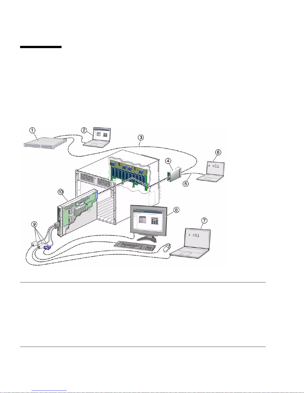
FIGURE 2-2 CMM and Server Module Connection Options
FIGURE 2-2 shows the connections to the server module SP and
Figure Leg end
1 Server (local or remote) 6 Computer connected to CMM RJ-45 serial connector
2 Computer connected to RJ-45 Ethernet (remote KVM
supported)
3 Ethernet cable connected to RJ-45 Ethernet
connector on the chassis management module
(CMM) (NET MGMT 0)
4 CMM with two connectors 9 Dongle cable with one RJ-45 serial, two USB 2
5 RJ-45 cable connected to CMM serial port (SER
MGT)
12 Sun Blade T6340 Server Module Installation and Administration Guide • April 2010
7 Computer connected to dongle cable RJ-45 serial
connector
8 Keyboard, video monitor, mouse (local KVM)
connectorsand one HD15-pin connector (VGA)
10 Sun Blade T6340 server module with service processor
(SP)
Page 23

Connecting to the Server Module
This section describes how to connect to the server module SP using one of the
methods listed below and described in the corresponding sections:
■ Connect to the CMM SP Using Ethernet Port NET MGT 0. Use the CMM service
processor proxy and the command line interface to navigate to the Sun Blade
T6340 server module SP ILOM firmware. You can also use the CMM SP web
interface to control the server module (Items 1 through 3 in
method is described in this getting started guide. See “Connecting Through the
Chassis CMM Ethernet Port” on page 13.
■ Connect to the CMM serial connector (SER MGT). Use the CMM SP proxy to
navigate to the server module SP ILOM firmware. This method supports CLI
access only (Item 6 in
FIGURE 2-2). See “Connecting to the Server Module SP
Through the Chassis CMM Serial Connector” on page 16.
■ Use a dongle cable to connect directly to the server module SP with an RJ45
serial connection. This method supports CLI access only (Items 7 and 9 in
FIGURE 2-2). Dongle cables are intended for setup, testing, or service purposes and
should be removed when not in use. See “Connecting to the Server Module SP
Using a Dongle Cable” on page 19.
■ Use a dongle cable to connect directly to the server module host with a local
keyboard, video, and mouse (local KVM). (Items 8 and 9). See “Connecting to
the Server Module With a Local Graphics Monitor or Local KVMS” on page 29.
FIGURE 2-2). This
■ Connect to the server module SP using the Ethernet (DHCP or static). This
method supports a CLI, or a web interface. The web interface can also control the
server module host using a remote keyboard, video and mouse (remote KVM).
(Items 1 through 3 in
FIGURE 2-2).
Connecting Through the Chassis CMM Ethernet
Port
The Ethernet port on the modular system chassis provides the most robust method
of connecting to the CMM and the server module SP. This connection supports both
the CLI and the web interface.
You can connect to the CMM through the RJ-45 NET MGT 0 Ethernet port.
Before you can use the Ethernet connection, you must know the IP addresses for the
CMM and server module SP to which you want to connect. To configure the IP
address on the Sun Blade T6340 server module, refer to “Configuring and Viewing
the IP Address for a Server Module SP” on page 20.
Chapter 2 Installation and Configuration 13
Page 24

▼ To Log In or Out of the SP Using the CLI
ILOM supports SSH access to the CLI over the Ethernet.
1. Start an SSH client.
2. Log in to the IP:.
$ ssh root@ipaddress
3. Type your password when prompted.
Note – The default user name is root, and the default password is changeme. See
“Changing the ILOM Password” on page 30 for information about changing the
default password.
For example:
$ ssh root@192.168.25.25
root@192.168.25.25's password:
Integrated Lights Out Manager
Version 1.0
Copyright 2007 Sun Microsystems, Inc. All rights reserved.
Warning: password is set to factory default.
4. Type exit to log out.
▼ To Log In or Out of the SP Using the Web Interface
1. To log in to the web interface, type the IP address of the SP into your web
browser.
The login screen is displayed:
14 Sun Blade T6340 Server Module Installation and Administration Guide • April 2010
Page 25
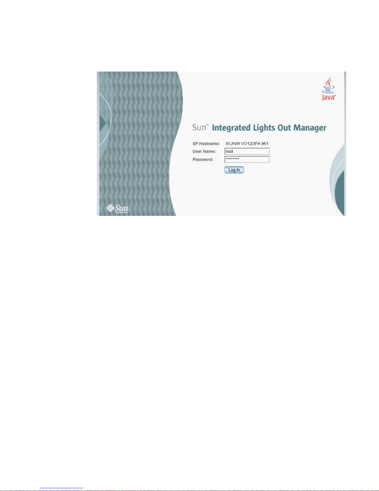
FIGURE 2-3 Web Interface Login Screen
2. Type your user name and password.
When you first try to access the web interface, it prompts you to type the default
user name and password. The default user name and password are:
■ Default user name: root
■ Default password: changeme
The default user name and password are in lowercase characters. See “Changing the
ILOM Password” on page 30 for information about changing the default password.
3. Click Log In.
The web interface is displayed.
4. To log out of the web interface, click the Log Out button at the top right of the
screen.
The log out screen is displayed.
Chapter 2 Installation and Configuration 15
Page 26
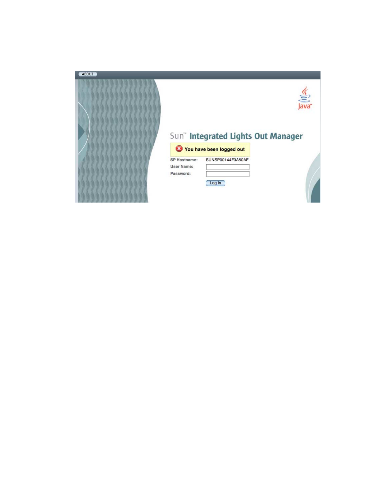
FIGURE 2-4 Web Interface Log Out Confirmation Screen
Connecting to the Server Module SP Through the Chassis
CMM Serial Connector
You can access the CMM ILOM by connecting a terminal or a terminal emulator to
the RJ-45 serial port on the chassis. Once the server module is installed in the
modular system chassis, you can connect to the server module SP by using the CLI
on the CMM ILOM software.
▼ To Connect Through the Chassis Serial Connector
1. Verify that your terminal, laptop, or terminal server is operational.
2. Configure the terminal device or terminal emulation software to use the
settings.
■ 8N1: eight data bits, no parity, one stop bit
■ 9600 baud (default, can be set to any standard rate up to 57600)
■ Disable hardware flow control (CTS/RTS)
3. Connect a serial cable from the serial port (SER MGT) on the chassis to a
terminal device.
Refer to the modular system chassis documentation for the location of the serial
port.
16 Sun Blade T6340 Server Module Installation and Administration Guide • April 2010
Page 27

Note – The serial port requires the pin assignments described in TABLE 2-1. Note that
these are the same as the serial cable connector for the Sun Advanced Lights Out
Manager (ALOM) or Remote System Control (RSC).
TABLE 2-1 Serial Management Port Pinouts
Pin Signal Description
1 Request To Send (RTS)
2 Data Terminal Ready (DTR)
3 Transmit Data (TXD)
4 Ground
5 Ground
6 Receive Data (RXD)
7 Data Carrier Detect (DCD)
8 Clear To Send (CTS)
4. Press Enter on the terminal device.
The connection between the terminal device and the CMM is established.
Note – If you connect a terminal or emulator to the serial port before it has been
powered up or during its power-up sequence, you will see boot messages.
When the system has booted, the CMM ILOM software displays its login prompt:
SUNCMMnnnnnnnnnn login:
The first string in the prompt is the default host name. It consists of the prefix
SUNCMM and the CMM ILOM MAC address. The MAC address for each service
processor is unique.
5. Log in to the CMM ILOM software:
a. Type the default user name, root.
b. Type the default password, changeme.
Once you have successfully logged in, the CMM ILOM displays its default
command prompt:
Chapter 2 Installation and Configuration 17
Page 28

->
You are now connected to the CMM ILOM software CLI.
6. Navigate to the server module ILOM by typing:
-> cd /CH/BLn/SP/cli
Where n is an integer (0 – 11) that identifies the target server module by the
chassis slot that the server module is installed in.
7. Type the start command.
A prompt is displayed.
8. Type y to continue or n to cancel.
After you type y, the ILOM software running on the server module SP prompts
for the password specific to that server module SP.
Note – The CMM ILOM logs on to the server module ILOM using the user name in
the user target under /CH/BLn/SP/cli (where n is the slot where the server
module is installed).
9. Type the password when prompted.
The default password is changeme.
The server module ILOM prompt is displayed.
See “Changing the ILOM Password” on page 30 for information about changing
the default password.
10. When you are done, type exit.
The server module ILOM exits and the CMM CLI prompt is displayed.
The following display shows an example of the login screen:
18 Sun Blade T6340 Server Module Installation and Administration Guide • April 2010
Page 29
-> cd /CH/BL8/SP/cli
/CH/BL8/SP/cli
-> start
Are you sure you want to start /CH/BL8/SP/cli (y/n)? y
start: Connecting to /CH/BL8/SP/cli using Single Sign On
Waiting for deamons to initialize...
Daemons ready
Password: changeme
Sun (TM) Integrated Lights Out Manager
Version 2.0.4.0
Copyright 2008 Sun Microsystems, Inc. All rights reserved.
Use is subject to license terms.
Warning: password is set to factory default.
-> exit Type the exit command to exit the server module SP and return to the
CMM.
start: The session with /CH/BL8/SP/cli has ended
Connecting to the Server Module SP Using a Dongle
Cable
A dongle cable allows you to connect a terminal directly to the server module.
Caution – Dongle cables are intended for setup, testing, or service purposes and
should be removed when not in use. They have not been evaluated for
electromagnetic compatibility (EMC) compliance and are not to be used during
normal system operation.
▼ To Connect to the Server Module SP Using a Dongle Cable
1. Connect a dongle cable to the UCP port on the front of the server module.
Refer to “Attaching a Serial Console to the Server Module” on page 7 for
information about attaching UCP dongle cables.
2. Connect a terminal or terminal emulator to the serial connector on the dongle
cable.
The ILOM login prompt is displayed.
Chapter 2 Installation and Configuration 19
Page 30

3. Type the user name and password when prompted.
The default user is root and the default password is changeme.
The server module ILOM prompt is displayed.
See “Changing the ILOM Password” on page 30 for information about changing
the default password.
4. When you are done, exit the ILOM software by typing:
-> exit
▼ To Connect a Storage Device to the Dongle
Cable
Connect the storage device directly to the dongle cable USB connector.
Configuring and Viewing the IP Address
for a Server Module SP
You can configure and view the network IP address for the server module SP in two
ways:
■ Connect to the CMM in the Sun Blade modular system chassis.
Refer to “Configuring and Viewing the IP Address for a Server Module SP
Through the CMM” on page 20.
■ Connect directly to the server module SP through the UCP.
Refer to “Configuring and Viewing the IP Address for a Server Module SP
Through the UCP” on page 25.
Configuring and Viewing the IP Address for a Server
Module SP Through the CMM
You can attach to the CMM on the modular system chassis through a serial port or
an Ethernet port:
■ CMM serial port – You can attach a terminal device. Refer to “Connecting to the
Server Module SP Through the Chassis CMM Serial Connector” on page 16.
20 Sun Blade T6340 Server Module Installation and Administration Guide • April 2010
Page 31

■ CMM Ethernet port – You can connect to your management network. Refer to
“Connecting Through the Chassis CMM Ethernet Port” on page 13.
After attaching to the CMM by using one of these ports, you can log in to the CMM
ILOM software to configure and view your server module IP address, whether the IP
address is assigned by DHCP or a static IP address.
▼ To View or Configure the IP Address for the Server
Module SP When Assigned by DHCP — Through the
CMM
1. Verify that your DHCP server is configured to accept new media access control
(MAC) addresses.
2. Attach to the CMM using the CMM serial or Ethernet port.
3. Find the IP address that DHCP has assigned to the server module SP.
A valid IP address may already have been assigned to the server module SP by
your DHCP server. To view the IP address that has been assigned, type:
-> show /CH/BLn/SP/network ipaddress
Where n is an integer representing the slot where the target server module is
installed. The CMM ILOM software displays the IP address currently assigned to
the server module SP.
If the assigned IP address is not valid, you should provide the MAC address for
the server module SP to your DHCP system administrator. In that case, proceed
to Step 4.
4. Obtain the MAC address for the server module SP.
■ MAC addresses are 12-digit hexadecimal strings in the format xx:xx:xx:xx:xx:xx
where x represents a single hexadecimal letter (0–9, A–F, a–f).
The Customer Information document shipped with your server module lists the
MAC address, or you can find it using this procedure:
a. Log in to the CMM ILOM software and type:
-> show /CH/BLn/SP/network macaddress
Where n is an integer representing the slot where the target server module is
installed. The CMM ILOM software displays the current MAC address.
b. Write down the MAC address and use it to configure your DHCP server.
Chapter 2 Installation and Configuration 21
Page 32

5. View the IP address that DHCP has assigned to the server module SP.
After a valid IP address has been assigned to the server module, view the IP
address, as described in Step 3.
▼ To View or Configure the IP Address for the Server
Module SP Using Static IP Addresses — Through the
CMM
1. Attach to the CMM using the CMM serial or Ethernet port.
2. (Optional) View the IP address.
■ To see all the IP address-related information, type:
-> show /CH/BLn/SP/network
■ To see only the IP address, type:
-> show /CH/BLn/SP/network ipaddress
3. Navigate to /CH/BLn/SP/network by typing the following command:
-> cd /CH/BLn/SP/network
4. Type one of the following commands:
■ To configure a static Ethernet configuration:
-> set pendingipdiscovery=static
-> set pendingipaddress=xxx.xxx.xx.xx
-> set pendingipnetmask=yyy.yyy.yyy.y
-> set pendingipgateway=zzz.zzz.zz.zzz
-> set commitpending=true
Where xxx.xxx.xx.xx, yyy.yyy.yyy.y and zzz.zzz.zz.zzz are the IP address,
netmask, and gateway for your ILOM and network configuration. To
determine these addresses, contact your system administrator.
■ To revert to a dynamic Ethernet configuration:
22 Sun Blade T6340 Server Module Installation and Administration Guide • April 2010
Page 33

-> set pendingipdiscovery=dhcp
-> set commitpending=true
The following display shows a typical session where the user looks at static
settings, configures them to be dynamic, then looks at the new settings.
Chapter 2 Installation and Configuration 23
Page 34

-> cd /CH/BL2/SP/network
-> show
/CH/BL2/SP/network
Targets:
Properties:
commitpending = (Cannot show property)
ipaddress = 10.6.42.42
ipdiscovery = static
ipgateway = 10.6.42.1
ipnetmask = 255.255.255.0
macaddress = 00:14:4F:3A:26:74
pendingipaddress = 10.6.42.42
pendingipdiscovery = static
pendingipgateway = 10.6.42.1
pendingipnetmask = 255.255.255.0
Commands:
cd
set
show
-> set pendingipdiscovery=dhcp
Set 'pendingipdiscovery' to 'dhcp'
-> set commitpending=true
Set 'commitpending' to 'true'
-> show
/CH/BL2/SP/network
Targets:
Properties:
commitpending = (Cannot show property)
ipaddress = 10.6.42.191
ipdiscovery = dhcp
ipgateway = 10.6.42.1
ipnetmask = 255.255.255.0
macaddress = 00:14:4F:3A:26:74
pendingipaddress = 10.6.42.191
pendingipdiscovery = dhcp
pendingipgateway = 10.6.42.1
pendingipnetmask = 255.255.255.0
Commands:
cd
set
show
24 Sun Blade T6340 Server Module Installation and Administration Guide • April 2010
Page 35

Configuring and Viewing the IP Address for a
Server Module SP Through the UCP
You can connect to the server module SP by one of these methods:
■ Through the front-panel universal connector port (UCP) using a dongle cable.
■ Through the SP Ethernet port. You must already know the IP address to use this
method, so it is not useful for configuration.
▼ To View or Configure the IP Address for the Server
Module SP When Assigned by DHCP — Through the
UCP
1. Verify that your DHCP server is configured to accept new media access control
(MAC) addresses.
2. Connect to the server module SP through the front-panel UCP using a dongle
cable.
Refer to “Connecting to the Server Module SP Using a Dongle Cable” on page 19.
3. Find the IP address that DHCP has assigned to the server module SP.
A valid IP address may already have been assigned to the server module SP by
your DHCP server. To view the IP address that has been assigned, type:
-> show /SP/network ipaddress
The ILOM software displays the IP address currently assigned to the server
module SP.
If the assigned IP address is not valid, you should provide the MAC address for
the server module SP to your DHCP system administrator. In that case, proceed
to Step 4.
4. Obtain the MAC address for the server module SP.
■ MAC addresses are 12-digit hexadecimal strings in the format xx:xx:xx:xx:xx:xx
where x represents a single hexadecimal letter (0–9, A–F, a–f).
The Customer Information document shipped with your server module lists the
MAC address, or you can find it using this procedure:
a. Type this command:
Chapter 2 Installation and Configuration 25
Page 36

-> show /SP/network macaddress
The ILOM software displays the current MAC address.
b. Write down the MAC address and use it to configure your DHCP server.
5. View the IP address that DHCP has assigned to the server module SP.
After a valid IP address has been assigned to the server module, view the IP
address. Refer to Step 3.
▼ To View or Configure the IP Address for the Server
Module SP Using Static IP Addresses — Through the
UCP and Dongle Cable
1. Connect to the server module SP through the front-panel UCP using the serial
connector on the dongle cable.
Refer to “Connecting to the Server Module SP Using a Dongle Cable” on page 19.
2. (Optional) View the IP address.
.
■ To see all the IP address-related information, type:
-> show /SP/network
■ To see only the IP address, type:
-> show /SP/network ipaddress
3. Follow the instructions in “To View or Configure the IP Address for the Server
Module SP Using Static IP Addresses — Through the CMM” on page 22, starting
with Step 3.
26 Sun Blade T6340 Server Module Installation and Administration Guide • April 2010
Page 37

Connecting a Remote Console or Remote
KVMS
These procedures are described in the Sun Integrated Lights Out Manager 2.0
Supplement for Sun Blade T6340 Server Modules, 820-3904 and chapter 12 of the Sun
Integrated Lights out Manager 2.0 User’s Guide, 820-1188.
Note – You should first read the Sun Integrated Lights Out Manager 2.0 Supplement for
Sun Blade T6340 Server Modules, 820-3904. That guide describes remote connection
procedures specific to the Sun Blade T6340 server module.
Switching Between the ILOM Prompt
and the System Console
The service processor has two management ports, serial and network (Ethernet). If
the system console is directed to use the serial management and network
management ports (the default configuration), these ports provide access to both the
system console and the ILOM command-line interface (the ILOM service processor
prompt), each on a separate channel (
FIGURE 2-5).
Chapter 2 Installation and Configuration 27
Page 38
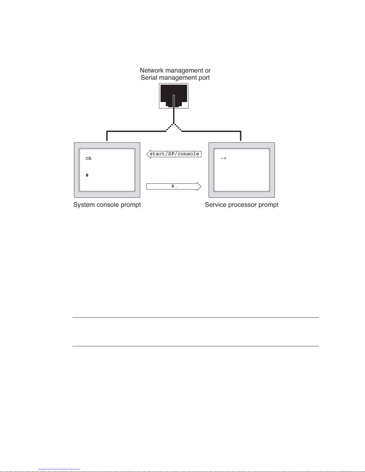
FIGURE 2-5 Separate System Console and Service Processor Channels
You can switch between the ILOM service processor prompt and the system console
at any time. However, you cannot access both at the same time from a single
terminal window or shell tool.
The prompt displayed on the terminal or shell tool tells you which channel you are
accessing:
■ The # or % prompt indicates that you are at the system console and that the
Solaris OS is running.
■ The ok prompt indicates that you are at the system console and that the server is
running under OpenBoot firmware control.
■ The -> prompt indicates that you are at the service processor.
Note – If no text or prompt appears, it might be because no console messages were
recently generated by the system. Pressing the terminal’s Enter or Return key should
produce a prompt.
▼ To Switch Between the ILOM Prompt and the
System Console
1. Establish an ILOM service processor session.
28 Sun Blade T6340 Server Module Installation and Administration Guide • April 2010
Page 39

2. To connect to the system console, at the ILOM command prompt, type:
-> start /SP/console
The start /SP/console command switches you to the system console.
3. To switch back to the -> prompt, type the #. (Hash-Period) escape sequence.
ok #.
Connecting to the Server Module With a
Local Graphics Monitor or Local KVMS
After initial system installation, you can install a local graphics monitor and
configure it to access the system console. You cannot use a local graphics monitor to
perform initial system installation, nor can you use a local graphics monitor to view
power-on self-test (POST) messages.
To install a local graphics monitor, you must have the following items:
■ Monitor with appropriate resolution to support the frame buffer
■ Supported USB keyboard
■ Supported USB mouse
To view a list of supported screen resolutions type:
host% fbconfig -res \?
For more information about graphics support, see Appendix B of the Sun Blade
T6340 Server Module Service Manual, 820-3902.
▼ To Access the System Console Through a Local
Graphics Monitor
1. Attach the monitor video cable to the HD-15 video connector on the cable
dongle.
Tighten the thumbscrews to secure the connection.
Chapter 2 Installation and Configuration 29
Page 40

2. Connect the monitor power cord to an AC outlet.
3. Connect the USB keyboard cable to one USB connector on the cable dongle.
4. Connect the USB mouse cable to the other USB connector.
5. Access the ok prompt.
For more information, see “To Obtain the ok Prompt” on page 62.
6. Set the OpenBoot configuration variables.
From the existing system console, type:
ok setenv input-device keyboard
ok setenv output-device screen
7. To cause the changes to take effect, type:
ok reset-all
The system stores the parameter changes, and boots automatically when the
OpenBoot configuration variable auto-boot? is set to true (the default value).
Note – To cause the parameter changes to take effect, you can also power cycle the
system using the front panel Power button.
You can now issue system commands and view system messages using your local
graphics monitor. Continue with your installation or diagnostic procedure, as
needed.
For more information about graphics configurations, see Appendix B of the Sun
Blade T6340 Server Module Service Manual, 820-3902.
Changing the ILOM Password
1. At the initial login prompt on the server module SP, log in using the default
administrator user name and password:
hostname login: root
Password: changeme
2. Use the ILOM password command to change the password.
30 Sun Blade T6340 Server Module Installation and Administration Guide • April 2010
Page 41

-> set /SP/users/root password
Enter new password: *******
Enter new password again: *******
->
After the root password has been set, on subsequent reboots, the ILOM CLI login
prompt is displayed.
Powering On the Host
After the service processor boots, the ILOM CLI prompt (->) is displayed the first
time the service processor is booted.
1. Type the start /SYS command.
You see an ILOM -> prompt on the system console. This indicates that the system
has reset. Issue the start /SYS command:
-> start /SYS
Are you sure you want to start /SYS (y/n)? y
Starting /SYS
2. Type the start /SP/console command.
-> start /SP/console
Are you sure you want to start /SP/console (y/n)? y
Serial console started. To stop, type #.
0:0:0>Scrub Memory....Done
0:0:0>SPU CWQ Tests...Done
0:0:0>MAU Tests...Done
The system may take six to 15 minutes to run POST diagnostics and boot. After
you type the start commands, the CPU and memory controllers initialize, and
eventually the OpenBoot PROM (OBP) firmware initializes. If a boot device
installed with the Solaris OS is accessible locally, that device will be booted.
Otherwise, the system will use the boot net command to seek a boot device on
the network.
Chapter 2 Installation and Configuration 31
Page 42

▼ To Power on the Server Module Manually
● You can also use a pointed object or stylus to press and release the recessed
Power button on the server front panel.
When main power is applied to the full server, the Power/OK LED above the Power
button lights and remains lit.
▼ To Shut Down Main Power Mode
To power off the server from main power mode, use one of the following two methods:
■ Graceful shutdown. Use a pointed object or other stylus to press and release the
Power button on the front panel. This causes Advanced Configuration and Power
Interface (ACPI) enabled operating systems to perform an orderly shutdown of
the operating system. Servers not running ACPI-enabled operating systems will
shut down to standby power mode immediately.
■ Emergency shutdown. Press and hold the Power button for four seconds to force
main power off and enter standby power mode.
When main power is off, the Power/OK LED on the front panel will begin flashing,
indicating that the server is in standby power mode.
Note – To power off the server completely, you must either remove the server
module from the chassis or disconnect the AC power cords from the back panel of
the chassis.
Installing the Solaris Operating System
on a Hard Drive
The basic configuration of the Sun Blade T6340 server module ships with or without
hard drives. If you ordered an optional hard drive with preinstalled software, refer
to “Preinstalled Software” on page 5.
If you ordered an optional hard drive without preinstalled software and want to
install the Solaris OS on the hard drive in slot 0, you must install the operating
system from your network.
For instructions on how to install the operating system from the network, refer to the
Solaris Installation Guide: Network-Based Installations. You can obtain this guide at:
32 Sun Blade T6340 Server Module Installation and Administration Guide • April 2010
Page 43

http://docs.sun.com/
JumpStart Server Installation
You can use a JumpStart server to install the OS. A JumpStart server consists of
several components:
■ Install client – The target system to be installed or upgraded.
■ Boot server – The network providing a failsafe operating system to the installing
client.
The boot image is architecture independent, providing basic operating system
services to all hardware supported by that operating system release. The Boot
Server provides RARP, TFTP and bootparam services.
■ Configuration server – A system that helps client systems determine unique profile
information.
Partition sizes, lists of software components to install, begin, and finish scripts are
specified in a profile served by the configuration server.
■ Install server – The source of the software packages to be installed on the client.
Note – The boot server, configuration server, and install server can be one server.
JumpStart Server Configuration
Specific instructions on how to configure a JumpStart server are out of the scope of
this document. However, configuring the JumpStart server consists of the following
tasks:
1. Load the Solaris OS.
2. Create the configuration server.
3. Create the configuration files.
4. Verify the configuration file syntax.
5. Share the installation directory.
6. Start the NFS server.
7. Configure the client access.
Chapter 2 Installation and Configuration 33
Page 44

The configuration and use of the JumpStart server depends on the configuration of
your network. For a full explanation of these steps and instructions on how to
configure the JumpStart server, refer to the following documents:
■ Configuring JumpStart Servers to Provision Sun x86-64 Systems by Pierre Reynes,
Network Systems Group, Sun BluePrints OnLine, February 2005
■ Building a JumpStart Infrastructure by Alex Noordergraaf, Enterprise Engineering,
Sun BluePrints OnLine, April 2001
You can obtain these documents from the following site:
http://www.sun.com/blueprints
34 Sun Blade T6340 Server Module Installation and Administration Guide • April 2010
Page 45

CHAPTER
3
Managing Disk Volumes
This chapter describes redundant array of independent disks (RAID) concepts, and
how to configure and manage RAID disk volumes using the Sun Blade T6340 server
module on-board serial attached SCSI (SAS) disk controller.
Note – The server module can be configured with a RAID Host Bus Adapter (HBA).
For managing HBA and disk volumes see the documentation for your HBA.
OS Patch Requirements
To configure and use RAID disk volumes on the server module, you must install the
appropriate patches. For the latest information on patches, see the latest product
notes for your system.
Installation procedures for patches are included in text README files that
accompany the patches.
Disk Volumes
The on-board disk controller treats disk volumes as logical disk devices comprising
one or more complete physical disks.
Once you create a volume, the operating system uses and maintains the volume as if
it were a single disk. By providing this logical volume management layer, the
software overcomes the restrictions imposed by physical disk devices.
35
Page 46

The on-board disk controller can create as many as two hardware RAID volumes.
The controller supports either two-disk RAID 1 (integrated mirror, or IM) volumes,
or up to eight-disk RAID 0 (integrated stripe, or IS) volumes.
Note – Due to the volume initialization that occurs on the disk controller when a
new volume is created, properties of the volume such as geometry and size are
unknown. RAID volumes created using the hardware controller must be configured
and labeled using format(1M) prior to use with the Solaris Operating System. See
“To Configure and Label a Hardware RAID Volume for Use in the Solaris Operating
System” on page 46, or the format(1M) man page for further details.
Volume migration (relocating all RAID volume disk members from one server
module to another server module) is not supported. If you must perform this
operation, contact your service provider.
RAID Technology
RAID technology enables the construction of a logical volume, made up of several
physical disks, in order to provide data redundancy, increased performance, or both.
The on-board disk controller supports both RAID 0 and RAID 1 volumes.
This section describes the RAID configurations supported by the on-board disk
controller:
■ Integrated stripe, or IS volumes (RAID 0)
■ Integrated mirror, or IM volumes (RAID 1)
Integrated Stripe Volumes (RAID 0)
Integrated stripe volumes are configured by initializing the volume across two or
more physical disks, and sharing the data written to the volume across each physical
disk in turn, or striping the data across the disks.
Integrated stripe volumes provide for a logical unit (LUN) that is equal in capacity
to the sum of all its member disks. For example, a three-disk IS volume configured
on 72-gigabyte drives will have a capacity of 216 gigabytes.
36 Sun Blade T6340 Server Module Installation and Administration Guide • April 2010
Page 47
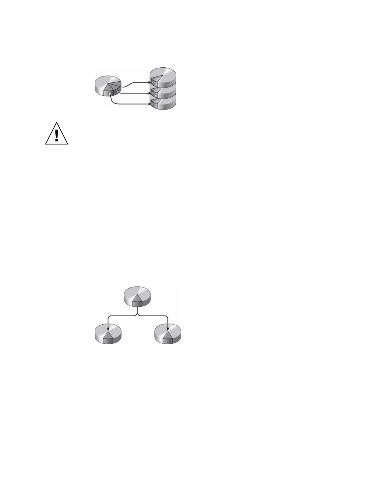
FIGURE 3-1 Graphical Representation of Disk Striping
Caution – There is no data redundancy in an IS volume configuration. Thus, if a
single disk fails, the entire volume fails, and all data is lost. If an IS volume is
manually deleted, all data on the volume is lost.
IS volumes are likely to provide better performance than IM volumes or single disks.
Under certain workloads, particularly some write or mixed read-write workloads,
I/O operations complete faster because the I/O operations are being handled in a
round-robin fashion, with each sequential block being written to each member disk
in turn.
Integrated Mirror Volumes (RAID 1)
Disk mirroring (RAID 1) is a technique that uses data redundancy (two complete
copies of all data stored on two separate disks) to protect against loss of data due to
disk failure. One logical volume is duplicated on two separate disks.
FIGURE 3-2 Graphical Representation of Disk Mirroring
Whenever the operating system needs to write to a mirrored volume, both disks are
updated. The disks are maintained at all times with exactly the same information.
When the operating system needs to read from the mirrored volume, the OS reads
from whichever disk is more readily accessible at the moment, which can result in
enhanced performance for read operations.
Chapter 3 Managing Disk Volumes 37
Page 48

Caution – Creating RAID volumes using the on-board disk controller destroys all
data on the member disks. The disk controller’s volume initialization procedure
reserves a portion of each physical disk for metadata and other internal information
used by the controller. Once the volume initialization is complete, you can configure
the volume and label it using the format(1M) utility. You can then use the volume
in the Solaris OS.
Hardware Raid Operations
The SAS controller supports mirroring and striping using the Solaris OS raidctl
utility.
A hardware RAID volume created under the raidctl utility behaves slightly
differently than a volume created using volume management software. Under a
software volume, each device has its own entry in the virtual device tree, and readwrite operations are performed to both virtual devices. Under hardware RAID
volumes, only one device appears in the device tree. Member disk devices are
invisible to the operating system and are accessed only by the SAS controller.
Physical Disk Slot Numbers, Physical Device
Names, and Logical Device Names for Non-RAID
Disks
To perform a disk hot-plug procedure, you must know the physical or logical device
name for the drive that you want to install or remove. If your system encounters a
disk error, often you can find messages about failing or failed disks in the system
console. This information is also logged in the /var/adm/messages files.
These error messages typically refer to a failed hard drive by its physical device
name (such as
name (such as
number (0 through 3).
/devices/pci@1f,700000/scsi@2/sd@1,0) or by its logical device
c1t1d0). In addition, some applications might report a disk slot
38 Sun Blade T6340 Server Module Installation and Administration Guide • April 2010
Page 49

You can use TABLE 3-1 to associate internal disk slot numbers with the logical and
physical device names for each hard drive.
TABLE 3-1 Disk Slot Numbers, Logical Device Names, and Physical Device Names
Disk Slot Number Logical Device Name
Slot 0 c1t0d0 /devices/pci@0/pci@0/pci@2/scsi@0/sd@0,0
Slot 1 c1t1d0 /devices/pci@0/pci@0/pci@2/scsi@0/sd@1,0
Slot 2 c1t2d0 /devices/pci@0/pci@0/pci@2/scsi@0/sd@2,0
Slot 3 c1t3d0 /devices/pci@0/pci@0/pci@2/scsi@0/sd@3,0
* The logical device names might appear differently on your system, depending on the number and type of add-on disk controllers
installed.
*
Physical Device Name
▼ To Create a Hardware Mirrored Volume
1. Verify which hard drive corresponds with which logical device name and
physical device name, using the raidctl command:
# raidctl
Controller: 1
Disk: 0.0.0
Disk: 0.1.0
Disk: 0.2.0
Disk: 0.3.0
Disk: 0.4.0
Disk: 0.5.0
Disk: 0.6.0
Disk: 0.7.0
See “Physical Disk Slot Numbers, Physical Device Names, and Logical Device
Names for Non-RAID Disks” on page 38.
Chapter 3 Managing Disk Volumes 39
Page 50

The preceding example indicates that no RAID volume exists. In another case:
# raidctl
Controller: 1
Volume:c1t0d0
Disk: 0.0.0
Disk: 0.1.0
Disk: 0.2.0
Disk: 0.3.0
Disk: 0.4.0
Disk: 0.5.0
Disk: 0.6.0
Disk: 0.7.0
In this example, a single volume (c1t0d0
) has been enabled.
The on-board SAS controller can configure as many as two RAID volumes. Prior to
volume creation, ensure that the member disks are available and that there are not
two volumes already created.
The RAID status might be:
■ OPTIMAL – Indicating that the RAID volume is online and fully synchronized.
■ SYNC – Indicating that the data between the primary and secondary member
disks in an IM are still synchronizing.
■ DEGRADED – Indicating that a member disk is failed or otherwise offline.
■ FAILED – Indicating that volume should be deleted and reinitialized. This failure
can occur when any member disk in an IS volume is lost, or when both disks are
lost in an IM volume.
The Disk Status column displays the status of each physical disk. Each member disk
might be GOOD, indicating that it is online and functioning properly, or it might be
FAILED, indicating that the disk has hardware or configuration issues that need to
be addressed.
For example, an IM with a secondary disk that has been removed from the chassis
appears as:
# raidctl -l c1t0d0
Volume Size Stripe Status Cache RAID
Sub Size Level
Disk
---------------------------------------------------------------c1t0d0 136.6G N/A DEGRADED OFF RAID1
0.1.0 136.6G GOOD
N/A 136.6G FAILED
40 Sun Blade T6340 Server Module Installation and Administration Guide • April 2010
Page 51
See the raidctl(1M) man page for additional details regarding volume and disk
status.
Note – The logical device names might appear differently on your system,
depending on the number and type of add-on disk controllers installed.
2. Type the following command:
# raidctl -c primary secondary
The creation of the RAID volume is interactive, by default. For example:
# raidctl -c c1t0d0 c1t1d0
Creating RAID volume c1t0d0 will destroy all data on member disks,
proceed (yes/no)? yes
...
Volume c1t0d0 is created successfully!
#
As an alternative, you can use the –f option to force the creation if you are sure of
the member disks, and sure that the data on both member disks can be lost. For
example:
# raidctl -f -c c1t0d0 c1t1d0
Volume c1t0d0 is created successfully!
#
When you create a RAID mirror, the secondary drive (in this case, c1t1d0)
disappears from the Solaris device tree.
3. To check the status of a RAID mirror, type the following command:
# raidctl -l c1t0d0
Volume Size Stripe Status Cache RAID
Sub Size Level
Disk
---------------------------------------------------------------c1t0d0 136.6G N/A SYNC OFF RAID1
0.0.0 136.6G GOOD
0.1.0 136.6G GOOD
The preceding example indicates that the RAID mirror is still resynchronizing with
the backup drive.
Chapter 3 Managing Disk Volumes 41
Page 52

The following example shows that the RAID mirror is synchronized and online.
# raidctl -l c1t0d0
Volume Size Stripe Status Cache RAID
Sub Size Level
Disk
---------------------------------------------------------------c1t0d0 136.6G N/A OPTIMAL OFF RAID1
0.0.0 136.6G GOOD
0.1.0 136.6G GOOD
The disk controller synchronizes IM volumes one at a time. If you create a second IM
volume before the first IM volume completes its synchronization, the first volume’s
RAID status will indicate SYNC, and the second volume’s RAID status will indicate
OPTIMAL. Once the first volume has completed, its RAID status changes to
OPTIMAL, and the second volume automatically starts synchronizing, with a RAID
status of SYNC.
Under RAID 1 (disk mirroring), all data is duplicated on both drives. If a disk fails,
replace it with a working drive and restore the mirror. For instructions, see “To
Perform a Mirrored Disk Hot-Plug Operation” on page 51.
For more information about the raidctl utility, see the raidctl(1M) man page.
▼ To Create a Hardware Mirrored Volume of the
Default Boot Device
Due to the volume initialization that occurs on the disk controller when a new
volume is created, the volume must be configured and labeled using the
format(1M) utility prior to use with the Solaris Operating System (see “To
Configure and Label a Hardware RAID Volume for Use in the Solaris Operating
System” on page 46). Because of this limitation, raidctl(1M) blocks the creation of
a hardware RAID volume if any of the member disks currently have a file system
mounted.
This section describes the procedure required to create a hardware RAID volume
containing the default boot device. Since the boot device always has a mounted file
system when booted, an alternate boot medium must be employed, and the volume
created in that environment. One alternate medium is a network installation image
in single-user mode. (Refer to the Solaris 10 Installation Guide for information about
configuring and using network-based installations.)
42 Sun Blade T6340 Server Module Installation and Administration Guide • April 2010
Page 53
1. Determine which disk is the default boot device.
From the OpenBoot ok prompt, type the printenv command, and if necessary
the devalias command, to identify the default boot device. For example:
ok printenv boot-device
boot-device = disk
ok devalias disk
disk /pci@0/pci@0/pci@2/scsi@0/disk@0,0
2. Type the boot net –s command.
ok boot net –s
3. Once the system has booted, use the raidctl(1M) utility to create a hardware
mirrored volume, using the default boot device as the primary disk.
See “To Create a Hardware Mirrored Volume” on page 39. For example:
# raidctl -c –r 1 c1t0d0 c1t1d0
Creating RAID volume c1t0d0 will destroy all data on member disks,
proceed (yes/no)? yes
...
Volume c1t0d0 is created successfully!
#
4. Install the volume with the Solaris OS using any supported method.
The hardware RAID volume c1t0d0 appears as a disk to the Solaris installation
program.
Note – The logical device names might appear differently on your system,
depending on the number and type of add-on disk controllers installed.
Chapter 3 Managing Disk Volumes 43
Page 54

▼ To Create a Hardware Striped Volume
1. Verify which hard drive corresponds with which logical device name and
physical device name.
See “Disk Slot Numbers, Logical Device Names, and Physical Device Names” on
page 39.
To verify the current RAID configuration, type:
# raidctl
Controller: 1
Disk: 0.0.0
Disk: 0.1.0
Disk: 0.2.0
Disk: 0.3.0
Disk: 0.4.0
Disk: 0.5.0
Disk: 0.6.0
Disk: 0.7.0
The preceding example indicates that no RAID volume exists.
Note – The logical device names might appear differently on your system,
depending on the number and type of add-on disk controllers installed.
2. Type the following command:
# raidctl -c –r 0 disk1 disk2 ...
44 Sun Blade T6340 Server Module Installation and Administration Guide • April 2010
Page 55

The creation of the RAID volume is interactive, by default. For example:
# raidctl -c -r 0 c1t1d0 c1t2d0 c1t3d0
Creating RAID volume will destroy all data on spare space of member
disks, proceed (yes/no)? yes
May 16 16:33:30 wgs57-06 scsi: /pci@0/pci@0/pci@2/scsi@0 (mpt0):
May 16 16:33:30 wgs57-06 Physical disk 0 created.
May 16 16:33:30 wgs57-06 scsi: /pci@0/pci@0/pci@2/scsi@0 (mpt0):
May 16 16:33:30 wgs57-06 Physical disk 1 created.
May 16 16:33:31 wgs57-06 scsi: /pci@0/pci@0/pci@2/scsi@0 (mpt0):
May 16 16:33:31 wgs57-06 Physical disk 2 created.
May 16 16:33:31 wgs57-06 scsi: /pci@0/pci@0/pci@2/scsi@0 (mpt0):
May 16 16:33:31 wgs57-06 Volume 3 is |enabled||optimal|
May 16 16:33:31 wgs57-06 scsi: /pci@0/pci@0/pci@2/scsi@0 (mpt0):
May 16 16:33:31 wgs57-06 Volume 3 is |enabled||optimal|
May 16 16:33:31 wgs57-06 scsi: /pci@0/pci@0/pci@2/scsi@0 (mpt0):
May 16 16:33:31 wgs57-06 Volume 3 created.
Volume c1t3d0 is created successfully!
#
When you create a RAID striped volume, the other member drives (in this case,
c1t2d0 and c1t3d0) disappear from the Solaris device tree.
As an alternative, you can use the –f option to force the creation if you are sure of
the member disks and sure that the data on all other member disks can be lost. For
example:
# raidctl -f -c -r 0 c1t1d0 c1t2d0 c1t3d0
...
Volume c1t3d0 is created successfully!
#
3. To check the status of a RAID striped volume, type the following command:
# raidctl -l
Controller: 1
Volume:c1t3d0
Disk: 0.0.0
Disk: 0.1.0
Disk: 0.2.0
Disk: 0.3.0
Disk: 0.4.0
Disk: 0.5.0
Disk: 0.6.0
Disk: 0.7.0
Chapter 3 Managing Disk Volumes 45
Page 56

4. To check the status of a RAID striped volume, type the following command:
# raidctl -l c1t3d0
Volume Size Stripe Status Cache RAID
Sub Size Level
Disk
---------------------------------------------------------------c1t3d0 N/A 64K OPTIMAL OFF RAID0
0.3.0 N/A GOOD
0.4.0 N/A GOOD
0.5.0 N/A GOOD
The example shows that the RAID striped volume is online and functioning.
Under RAID 0 (disk striping), there is no replication of data across drives. The data
is written to the RAID volume across all member disks in a round-robin fashion. If
any one disk is lost, all data on the volume is lost. For this reason, RAID 0 cannot be
used to ensure data integrity or availability, but can be used to increase write
performance in some scenarios.
For more information about the raidctl utility, see the raidctl(1M) man page.
▼ To Configure and Label a Hardware RAID
Volume for Use in the Solaris Operating System
After creating a RAID volume using raidctl, use format(1M) to configure and
label the volume before attempting to use it in the Solaris Operating System.
1. Start the format utility:
# format
The format utility might generate messages about corruption of the current label on
the volume, which you are going to change. You can safely ignore these messages.
2. Select the disk name that represents the RAID volume that you have
configured.
46 Sun Blade T6340 Server Module Installation and Administration Guide • April 2010
Page 57

In this example, c1t2d0 is the logical name of the volume.
# format
Searching for disks...done
AVAILABLE DISK SELECTIONS:
0. c1t0d0 <SUN72G cyl 14087 alt 2 hd 24 sec 424>
/pci@0/pci@0/pci@2/scsi@0/sd@0,0
1. c1t1d0 <SUN72G cyl 14087 alt 2 hd 24 sec 424>
/pci@0/pci@0/pci@2/scsi@0/sd@1,0
2. c1t2d0 <SUN72G cyl 14087 alt 2 hd 24 sec 424>
/pci@0/pci@0/pci@2/scsi@0/sd@2,0
3. c1t3d0 <SUN72G cyl 14087 alt 2 hd 24 sec 424>
/pci@0/pci@0/pci@2/scsi@0/sd@3,0
4. c1t4d0 <SUN73G cyl 14087 alt 2 hd 24 sec 424>
/pci@0/pci@0/pci@2/scsi@0/sd@4,0
5. c1t5d0 <SUN72G cyl 14087 alt 2 hd 24 sec 424>
/pci@0/pci@0/pci@2/scsi@0/sd@5,0
6. c1t6d0 <SUN72G cyl 14087 alt 2 hd 24 sec 424>
/pci@0/pci@0/pci@2/scsi@0/sd@6,0
7. c1t7d0 <SUN72G cyl 14087 alt 2 hd 24 sec 424>
/pci@0/pci@0/pci@2/scsi@0/sd@7,0
Specify disk (enter its number): 2
selecting c1t2d0
[disk formatted]
FORMAT MENU:
disk - select a disk
type - select (define) a disk type
partition - select (define) a partition table
current - describe the current disk
format - format and analyze the disk
repair - repair a defective sector
label - write label to the disk
analyze - surface analysis
defect - defect list management
backup - search for backup labels
verify - read and display labels
save - save new disk/partition definitions
inquiry - show vendor, product and revision
volname - set 8-character volume name
!<cmd> - execute <cmd>, then return
quit
Chapter 3 Managing Disk Volumes 47
Page 58

3. Type the type command at the format prompt, then select 0 (zero) to
autoconfigure the volume.
For example:
format> type
VAILABLE DRIVE TYPES:
0. Auto configure
1. Quantum ProDrive 80S
2. Quantum ProDrive 105S
3. CDC Wren IV 94171-344
4. SUN0104
5. SUN0207
6. SUN0327
7. SUN0340
8. SUN0424
9. SUN0535
10. SUN0669
11. SUN1.0G
12. SUN1.05
13. SUN1.3G
14. SUN2.1G
15. SUN2.9G
16. Zip 100
17. Zip 250
18. Peerless 10GB
19. LSILOGIC-LogicalVolume-3000
20. SUN72G
21. SUN73G
22. other
Specify disk type (enter its number)[19]: 0
c1t2d0: configured with capacity of 136.71GB
<SUN146G cyl 14087 alt 2 hd 24 sec 848>
selecting c1t2d0
[disk formatted]
4. Use the partition command to partition, or slice, the volume according to
your desired configuration.
See the format(1M) man page for additional details.
5. Write the new label to the disk using the label command.
format> label
Ready to label disk, continue? yes
48 Sun Blade T6340 Server Module Installation and Administration Guide • April 2010
Page 59

6. Verify that the new label has been written by printing the disk list using the
disk command.
format> disk
AVAILABLE DISK SELECTIONS:
0. c1t0d0 <SUN72G cyl 14084 alt 2 hd 24 sec 424>
/pci@0/pci@0/pci@2/scsi@0/sd@0,0
1. c1t1d0 <SUN72G cyl 14084 alt 2 hd 24 sec 424>
/pci@0/pci@0/pci@2/scsi@0/sd@1,0
2. c1t2d0 <LSILOGIC-LogicalVolume-3000 cyl 65533 alt 2 hd
16 sec 273>
/pci@0/pci@0/pci@2/scsi@0/sd@2,0
...
Note that c1t2d0 now has a type indicating it is an LSILOGIC-LogicalVolume.
7. Exit the format utility.
The volume can now be used in the Solaris OS.
Note – The logical device names might appear differently on your system,
depending on the number and type of add-on disk controllers installed.
▼ To Delete a Hardware RAID Volume
1. Verify which hard drive corresponds with which logical device name and
physical device name.
See “Disk Slot Numbers, Logical Device Names, and Physical Device Names” on
page 39.
2. Determine the name of the RAID volume, type:
# raidctl
Controller: 1
Volume:c1t0d0
Disk: 0.0.0
Disk: 0.1.0
...
In this example, the RAID volume is
c1t1d0.
Chapter 3 Managing Disk Volumes 49
Page 60
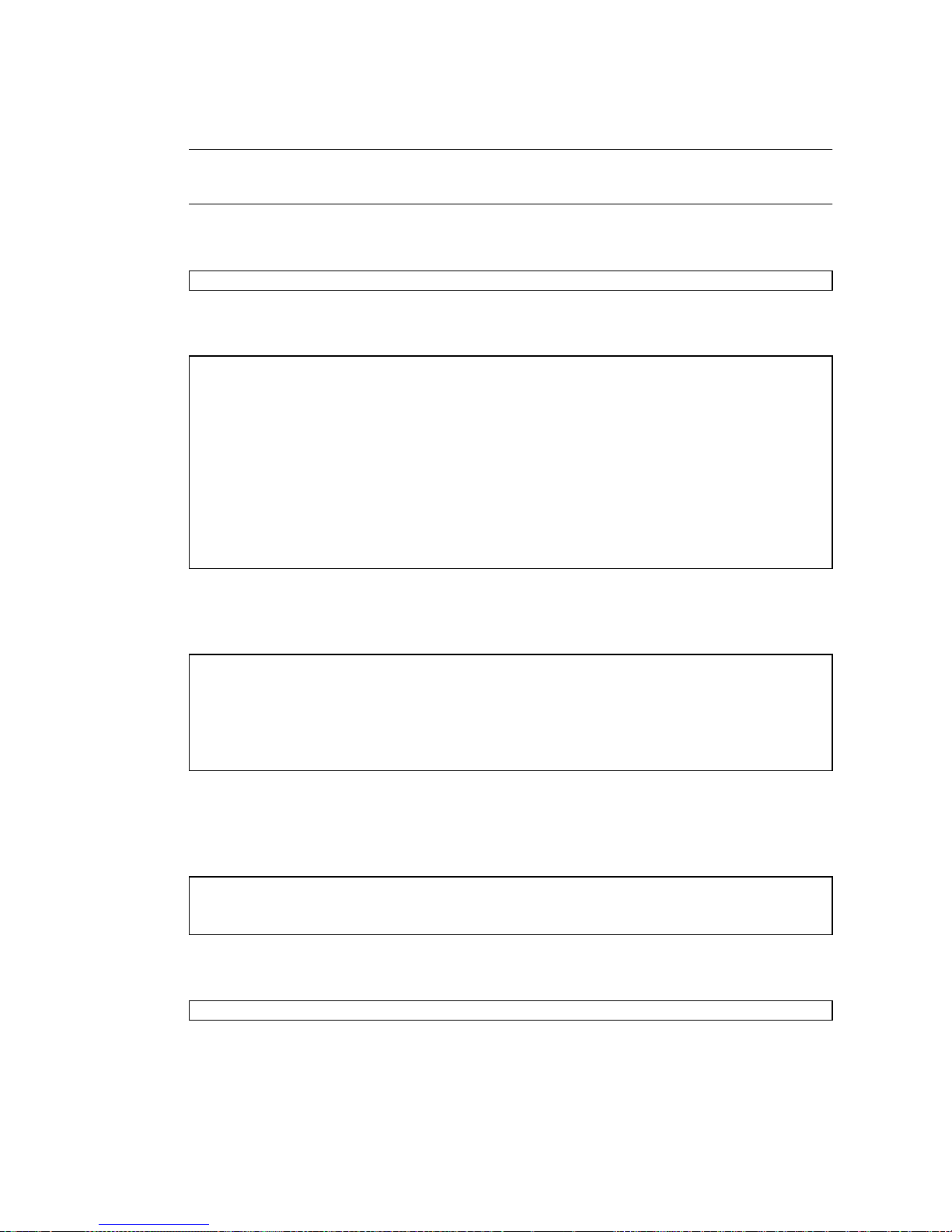
Note – The logical device names might appear differently on your system,
depending on the number and type of add-on disk controllers installed.
3. To delete the volume, type the following command:
# raidctl -d mirrored-volume
For example:
# raidctl -d c1t0d0
Deleting RAID volume c1t0d0 will destroy all data it contains,
proceed (yes/no)? yes
/pci@0/pci@0/pci@2/scsi@0 (mpt0):
Volume 0 deleted.
/pci@0/pci@0/pci@2/scsi@0 (mpt0):
Physical disk 0 deleted.
/pci@0/pci@0/pci@2/scsi@0 (mpt0):
Physical disk 1 deleted.
Volume c1t0d0 is deleted successfully!
If the RAID volume is an IS volume, the deletion of the RAID volume is interactive,
for example:
# raidctl -d c1t0d0
Deleting volume c1t0d0 will destroy all data it contains, proceed
(yes/no)? yes
...
Volume c1t0d0 is deleted successfully!
#
The deletion of an IS volume results in the loss of all data that it contains. As an
alternative, you can use the –f option to force the deletion if you are sure that you
no longer need the IS volume or the data it contains. For example:
# raidctl -f -d c1t0d0
Volume c1t0d0 is deleted successfully!
#
4. To confirm that you have deleted the RAID array, type the following command:
# raidctl
50 Sun Blade T6340 Server Module Installation and Administration Guide • April 2010
Page 61

For example:
# raidctl
Controller: 1
Disk: 0.0.0
Disk: 0.1.0
...
For more information, see the raidctl(1M) man page.
▼ To Perform a Mirrored Disk Hot-Plug Operation
1. Verify which hard drive corresponds with which logical device name and
physical device name.
See “Disk Slot Numbers, Logical Device Names, and Physical Device Names” on
page 39.
2. To confirm a failed disk, type the following command:
# raidctl
If the Disk Status is FAILED, then the drive can be removed and a new drive
inserted. Upon insertion, the new disk should be GOOD and the volume should be
SYNC.
For example:
# raidctl -l c1t0d0
Volume Size Stripe Status Cache RAID
Sub Size Level
Disk
---------------------------------------------------------------c1t0d0 136.6G N/A DEGRADED OFF RAID1
0.0.0 136.6G GOOD
0.1.0 136.6G FAILED
This example indicates that the disk mirror has degraded due to a failure in disk
c1t2d0 (0.1.0).
Note – The logical device names might appear differently on your system,
depending on the number and type of add-on disk controllers installed.
Chapter 3 Managing Disk Volumes 51
Page 62

3. Remove the hard drive, as described in your server module service manual.
There is no need to use a software command to bring the drive offline when the
drive has failed.
4. Install a new hard drive, as described in your server module service manual.
The RAID utility automatically restores the data to the disk.
5. To check the status of a RAID rebuild, type the following command:
# raidctl
For example:
# raidctl -l c1t0d0
Volume Size Stripe Status Cache RAID
Sub Size Level
Disk
---------------------------------------------------------------c1t0d0 136.6G N/A SYNC OFF RAID1
0.0.0 136.6G GOOD
0.1.0 136.6G GOOD
This example indicates that RAID volume c1t1d0 is resynchronizing.
If you type the command again once synchronization has completed, it indicates that
the RAID mirror is finished resynchronizing and is back online:
# raidctl -l c1t0d0
Volume Size Stripe Status Cache RAID
Sub Size Level
Disk
---------------------------------------------------------------c1t0d0 136.6G N/A OPTIMAL OFF RAID1
0.0.0 136.6G GOOD
0.1.0 136.6G GOOD
For more information, see the raidctl(1M) man page.
52 Sun Blade T6340 Server Module Installation and Administration Guide • April 2010
Page 63

▼ To Perform a Nonmirrored Disk Hot-Plug
Operation
1. Verify which hard drive corresponds with which logical device name and
physical device name.
See “Disk Slot Numbers, Logical Device Names, and Physical Device Names” on
page 39. Ensure that no applications or processes are accessing the hard drive.
2. Type the following command:
# cfgadm -al
For example:
# cfgadm –al
Ap_Id Type Receptacle Occupant Condition
c1 scsi-bus connected configured unknown
c1::dsk/c1t0d0 disk connected configured unknown
c1::dsk/c1t1d0 disk connected configured unknown
c1::dsk/c1t2d0 disk connected configured unknown
c1::dsk/c1t3d0 disk connected configured unknown
c1::dsk/c1t4d0 disk connected configured unknown
c1::dsk/c1t5d0 disk connected configured unknown
c1::dsk/c1t6d0 disk connected configured unknown
c1::dsk/c1t7d0 disk connected configured unknown
usb0/1 unknown empty unconfigured ok
usb0/2 unknown empty unconfigured ok
usb0/3 unknown empty unconfigured ok
usb1/1 unknown empty unconfigured ok
usb1/2 unknown empty unconfigured ok
usb2/1 unknown empty unconfigured ok
usb2/2 usb-storage connected configured ok
usb2/3 unknown empty unconfigured ok
usb2/4 usb-hub connected configured ok
usb2/4.1 unknown empty unconfigured ok
usb2/4.2 unknown empty unconfigured ok
usb2/4.3 unknown empty unconfigured ok
usb2/4.4 unknown empty unconfigured ok
usb2/5 unknown empty unconfigured ok
#
Note – The logical device names might appear differently on your system,
depending on the number and type of add-on disk controllers installed.
Chapter 3 Managing Disk Volumes 53
Page 64

The -al options return the status of all SCSI devices, including buses and USB
devices. In this example, no USB devices are connected to the system.
Note that while you can use the Solaris OS cfgadm install_device and cfgadm
remove_device commands to perform a hard drive hot-plug procedure, these
commands issue the following warning message when you invoke them on a bus
containing the system disk:
# cfgadm -x remove_device c1::dsk/c1t3d0
Removing SCSI device: /devices/pci@0/pci@0/pci@2/scsi@0/sd@3,0
This operation will suspend activity on SCSI bus: c1
Continue (yes/no)? yes
cfgadm: Hardware specific failure: failed to suspend:
Resource Information
------------------ ----------------------/dev/dsk/c1t1d0s0 mounted filesystem "/"
This warning is issued because these commands attempt to quiesce the (SAS) SCSI
bus, but the server firmware prevents it. This warning message can be safely
ignored, but the following step avoids this warning message altogether.
3. Remove the hard drive from the device tree.
Type the following command:
# cfgadm -c unconfigure Ap-Id
For example:
# cfgadm -c unconfigure c0::dsk/c1t3d0
This example removes c1t3d0 from the device tree. The blue OK-to-Remove LED
lights.
54 Sun Blade T6340 Server Module Installation and Administration Guide • April 2010
Page 65

4. Verify that the device has been removed from the device tree.
Type the following command:
# cfgadm -al
Ap_Id Type Receptacle Occupant Condition
c1 scsi-bus connected configured unknown
c1::dsk/c1t0d0 disk connected configured unknown
c1::dsk/c1t1d0 disk connected configured unknown
c1::dsk/c1t2d0 disk connected configured unknown
c1::dsk/c1t3d0 disk connected unconfigured unknown
c1::dsk/c1t4d0 disk connected configured unknown
c1::dsk/c1t5d0 disk connected configured unknown
c1::dsk/c1t6d0 disk connected configured unknown
c1::dsk/c1t7d0 disk connected configured unknown
usb0/1 unknown empty unconfigured ok
usb0/2 unknown empty unconfigured ok
usb0/3 unknown empty unconfigured ok
usb1/1 unknown empty unconfigured ok
usb1/2 unknown empty unconfigured ok
usb2/1 unknown empty unconfigured ok
usb2/2 usb-storage connected configured ok
usb2/3 unknown empty unconfigured ok
usb2/4 usb-hub connected configured ok
usb2/4.1 unknown empty unconfigured ok
usb2/4.2 unknown empty unconfigured ok
usb2/4.3 unknown empty unconfigured ok
usb2/4.4 unknown empty unconfigured ok
usb2/5 unknown empty unconfigured ok
#
Note that c1t3d0 is now unavailable and unconfigured. The corresponding
hard drive OK-to-Remove LED is lit.
5. Remove the hard drive, as described in your server module service manual.
The blue OK-to-Remove LED is extinguished when you remove the hard drive.
6. Install a new hard drive, as described in your server module service manual.
7. Configure the new hard drive.
Type the following command:
# cfgadm -c configure Ap-Id
For example:
# cfgadm -c configure c1::dsk/c1t3d0
Chapter 3 Managing Disk Volumes 55
Page 66

The green Activity LED flashes as the new disk at c1t3d0 is added to the device
tree.
8. Verify that the new hard drive is in the device tree.
Type the following command:
# cfgadm -al
Ap_Id Type Receptacle Occupant Condition
c1 scsi-bus connected configured unknown
c1::dsk/c1t0d0 disk connected configured unknown
c1::dsk/c1t1d0 disk connected configured unknown
c1::dsk/c1t2d0 disk connected configured unknown
c1::dsk/c1t3d0 disk connected configured unknown
c1::dsk/c1t4d0 disk connected configured unknown
c1::dsk/c1t5d0 disk connected configured unknown
c1::dsk/c1t6d0 disk connected configured unknown
c1::dsk/c1t7d0 disk connected configured unknown
usb0/1 unknown empty unconfigured ok
usb0/2 unknown empty unconfigured ok
usb0/3 unknown empty unconfigured ok
usb1/1 unknown empty unconfigured ok
usb1/2 unknown empty unconfigured ok
usb2/1 unknown empty unconfigured ok
usb2/2 usb-storage connected configured ok
usb2/3 unknown empty unconfigured ok
usb2/4 usb-hub connected configured ok
usb2/4.1 unknown empty unconfigured ok
usb2/4.2 unknown empty unconfigured ok
usb2/4.3 unknown empty unconfigured ok
usb2/4.4 unknown empty unconfigured ok
usb2/5 unknown empty unconfigured ok
#
Note that c1t3d0 is now listed as configured.
56 Sun Blade T6340 Server Module Installation and Administration Guide • April 2010
Page 67

CHAPTER
4
OpenBoot PROM Features
This chapter describes some OpenBoot PROM features and procedures.
OpenBoot ok Prompt
Oracle’s Sun Blade T6340 server module with the Solaris OS installed operates at
different run levels. For a full description of run levels, refer to the Solaris system
administration documentation.
Most of the time, you operate the server module at run level 2 or run level 3, which
are multiuser states with access to full system and network resources. Occasionally,
you might operate the system at run level 1, which is a single-user administrative
state. However, the lowest operational state is run level 0. At this state, it is safe to
turn off power to the system.
When the server module is at run level 0, the ok prompt appears. This prompt
indicates that the OpenBoot firmware is in control of the system.
There are a number of scenarios under which OpenBoot firmware control can occur:
■ By default, before the operating system is installed the system comes up under
OpenBoot firmware control.
■ When the auto-boot? OpenBoot configuration variable is set to false, the
system boots to the ok prompt.
■ After the Solaris OS is halted, the system transitions to run level 0 in an orderly
way.
■ During the boot process, when there is a serious hardware problem that prevents
the operating system from running, the system reverts to OpenBoot firmware
control.
■ When you deliberately place the system under firmware control in order to
execute firmware-based commands, you have the ok prompt.
57
Page 68

The last scenario most often concerns you as an administrator, since there will be
times when you need to reach the ok prompt. Several ways to do this are outlined in
“Reaching the ok Prompt” on page 58. For detailed instructions, see “Reaching the
ok Prompt” on page 58.
Openboot ok Prompt Not Available After Solaris
OS Has Started
The OpenBoot firmware is not available and might be removed from memory once
the Solaris OS starts.
To reach the ok prompt from the Solaris OS, you must first halt the domain. Use the
Solaris OS halt (1M) command to halt the domain.
Reaching the ok Prompt
There are several ways to reach the ok prompt, depending on the state of the system
and the means by which you are accessing the system console. In decreasing order of
desirability, the list is as follows:
Note – To reach the ok prompt after a shutdown or reset of the server module, the
auto-boot? option must be set to false. Also, you must shut down or restart the
Solaris OS to get to the ok prompt. You cannot reach the ok prompt from the Solaris
OS (see “Openboot ok Prompt Not Available After Solaris OS Has Started” on
page 58).
■ Graceful shutdown
■ Graceful reset of the control domain using the ILOM reset command
■ Manual system reset
■ The Break key or the equivalent ILOM service processor command pair:
-> set /HOST send_break_action=break
-> start /SP/console –force
A discussion of each method follows. For step-by-step instructions, see “Procedures
for Obtaining the ok Prompt” on page 61.
Note – As a rule, before suspending the operating system you should back up files,
warn users of the impending shutdown, and halt the system in an orderly manner.
However, it is not always possible to take such precautions, especially if the system
is malfunctioning.
58 Sun Blade T6340 Server Module Installation and Administration Guide • April 2010
Page 69
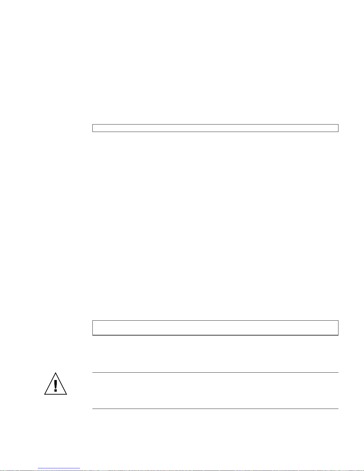
Graceful Shutdown
The preferred method of reaching the ok prompt is to shut down the operating
system by typing an appropriate command (for example, the init,or
uadmin commands) as described in Solaris system administration documentation.
For example, if you type init 0 at the Solaris prompt the system gradually takes
you to the ok prompt:
ok
If the operating system is already halted, you can use the start /SP/console
command without using set /HOST send_break_action=break to reach the ok
prompt.
Gracefully shutting down the system prevents data loss, enables you to warn users
beforehand, and causes minimal disruption. You can usually perform a graceful
shutdown, provided the Solaris OS is running and the hardware has not experienced
serious failure.
You can perform a graceful system shutdown from the ILOM service processor
command prompt using the stop /SYS command.
You can also use the system Power button to initiate a graceful system shutdown.
Graceful Reset of the Control Domain With ILOM reset
Command
Use the ILOM reset command to gracefully reset the control domain and obtain
the ok prompt. If a graceful shutdown is not possible, a forced shutdown is
performed. To use this method to obtain the ok prompt, you must first set the
control domain auto-boot option to false. For example:
-> set /HOST/domain/control auto-boot=disable
-> reset /HOST/domain/control
Manual System Reset
Caution – Forcing a manual system reset results in loss of system state data and
should be attempted only as a last resort. After a manual system reset, all state
information is lost, which inhibits troubleshooting the cause of the problem until the
problem reoccurs.
Chapter 4 OpenBoot PROM Features 59
Page 70

Use the ILOM service processor reset /SYS command, or start /SYS and
stop /SYS commands, to reset the server module. For example
▼ To Reset the System Manually
1. Type:
-> set /HOST/bootmode script="setenv auto-boot? false"
The auto-boot? setting is permanent. The setting remains false until
deliberately changed.
2. Press Enter.
3. Type:
-> reset /SYS
-> start /SP/console
Reaching the ok prompt by performing a manual system reset or by power cycling
the system should be the method of last resort. Using these commands results in the
loss of all system coherence and state information. A manual system reset could
corrupt the server module file systems, although the fsck command usually
restores them. Use this method only when nothing else works.
Caution – Accessing the ok prompt shuts down the Solaris OS. You cannot return
to the Solaris OS without rebooting the OS, for example with the boot command.
▼ To Shut Down the Server Module Using the Break Key
or the Equivalent Pair of ILOM Commands
When it is impossible or impractical to shut down the system gracefully, you can get
to the ok prompt, if you have an alphanumeric terminal attached to the server
module, by pressing the Break key.
The equivalent method uses the following pair of commands:
60 Sun Blade T6340 Server Module Installation and Administration Guide • April 2010
Page 71
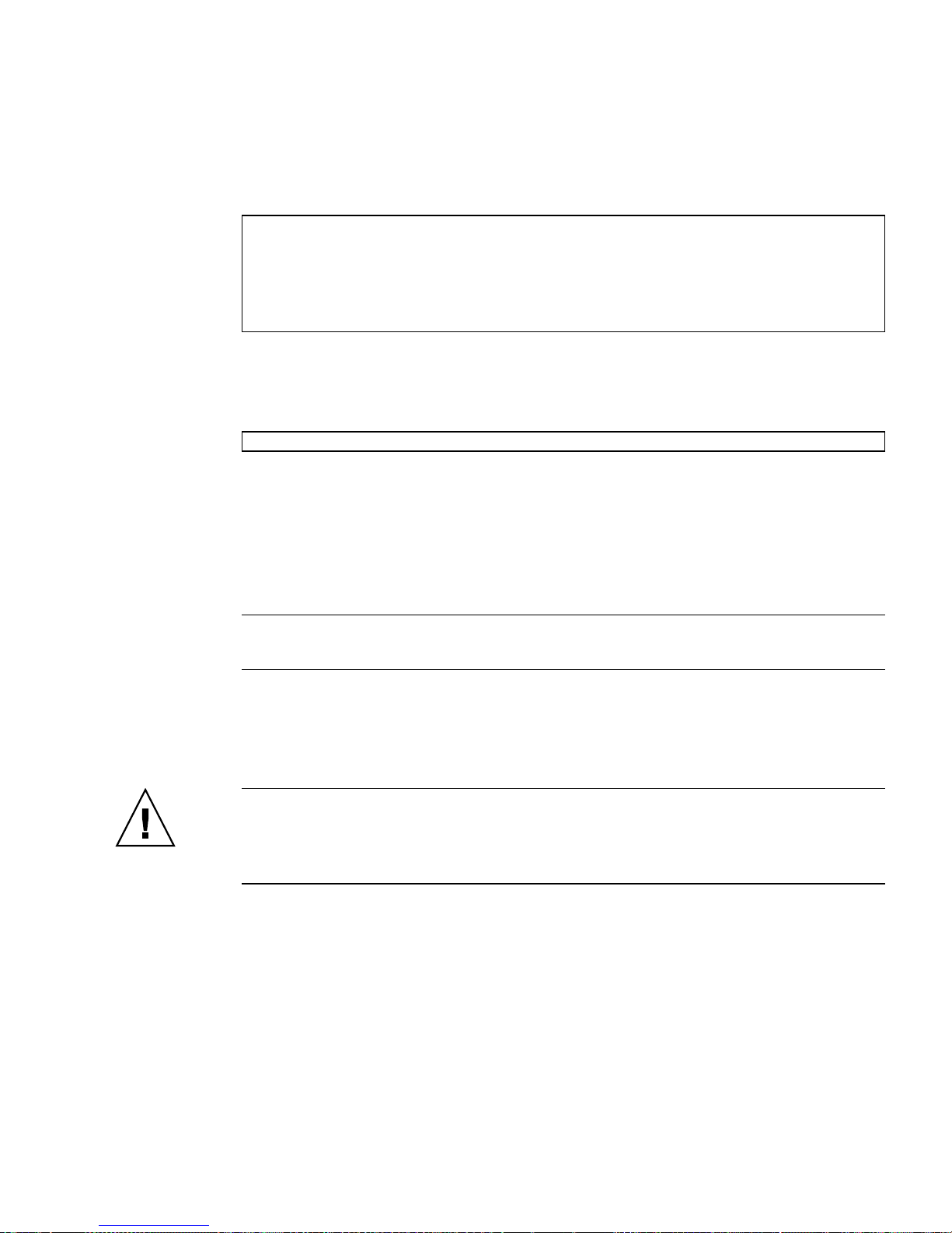
1. Type set /HOST send_break_action=break
This command forces a running server module to drop to a menu. For example:
-> set /HOST send_break_action=break
Set ’send_break_action’ to ’break’
-> start /SP/console
Are you sure you want to start /SP/console (y/n)? y
Serial console started. To stop, type #.
2. Press Enter.
The server module responds with:
c)ontinue, s)ync, r)eset
3. Select r to reset the system and stop at the ok prompt if the auto-boot?
option is set to false.
Selecting c returns you to the Solaris prompt without reset.
Selecting s causes a core dump, a hard reset of the control domain (the host if no
guest domains have been configured), then boots the Solaris OS.
Note – These methods of reaching the ok prompt will only work if the system
console has been left in the default setting of virtual-console.
Procedures for Obtaining the ok Prompt
Caution – Obtaining the ok prompt shuts down all application and operating
system software. After you issue firmware commands and run firmware-based tests
from the ok prompt, you cannot resume where the OS or applications left off. You
must reboot the Solaris OS after reaching the ok prompt.
If possible, back up system data before starting this procedure. Also exit or stop all
applications, and warn users of the impending loss of service. For information about
the appropriate backup and shutdown procedures, see Solaris system administration
documentation.
Chapter 4 OpenBoot PROM Features 61
Page 72

▼ To Obtain the ok Prompt
1. Decide which method you need to use to reach the ok prompt.
2. Follow the appropriate instructions in
FIGURE 4-1 Procedures for Accessing the ok Prompt
Access Method What to Do
Graceful shutdown of the
Solaris OS
Graceful reset of the
control domain using the
ILOM reset command
Manual system reset From the -> prompt, type:
Break key or equivalent
ILOM break commands
From a shell or command tool window, type an appropriate command (for
example, the init 0oruadmin 2 0 commands) as described in Solaris system
administration documentation.
From the -> prompt in the control domain, type:
-> set /HOST/domain/control auto-boot=disable
-> reset /HOST/domain/control
-> set /HOST/bootmode script="setenv auto-boot? false"
Press Enter.
Then type:
-> reset /SYS
-> start /SP/console
From an alphanumeric terminal configured to access the system console, press the
Break key.
After the break, if a debugger is present the domain breaks to KMDB debugger
prompt, which allows access to the c)continue, s)ync, r)eset? prompt. If
a debugger is not present, the c)continue, s)ync, r)eset? prompt occurs:
• c – returns to the Solaris OS
• s – forces synchronization (sync) of the filesystem, resulting in a core dump
• r – resets the domain and reboots to the Solaris OS if the auto-boot? option is
set to true, or stops at the ok prompt if the auto-boot? option is set to
false.
FIGURE 4-1.
62 Sun Blade T6340 Server Module Installation and Administration Guide • April 2010
Page 73

OpenBoot Configuration Variables on
the SP
TABLE 4-1 describes the OpenBoot firmware configuration variables. The OpenBoot
configuration variables are printed here in the order in which they appear when you
type the following command: ok printenv
TABLE 4-1 OpenBoot Configuration Variables Stored on the Service Processor
Variable Name Possible Values Default Value Description
{0} ok printenv None None Printenv command displays the variables
below.
ttya-rts-dtr-off true, false false If true, operating system does not assert
rts (request-to-send) and dtr
(data-transfer-ready) on serial management
port.
ttya-ignore-cd true, false true If true, operating system ignores carrier-
detect on TTYA port.
reboot-command
security-mode none, command,
full
security-password variable-name No default Firmware security password if
security-#badlogins 0 No default Number of incorrect security password
verbosity min, normal,
max
pci-mem64? true, false true
diag-switch? true, false false If true, OpenBoot verbosity is set to
local-mac-address? true, false true If true, network drivers use their own
fcode-debug? true, false false If true, include name fields for
No default Firmware security level.
security-mode is not none (never
displayed). Do not set this directly.
attempts.
min Controls mount and detail of firmware
output.
maximum
If false, OpenBoot verbosity is set to
minimum
MAC address, not the server MAC address.
plug-in device FCodes.
Chapter 4 OpenBoot PROM Features 63
Page 74

TABLE 4-1 OpenBoot Configuration Variables Stored on the Service Processor
Variable Name Possible Values Default Value Description
scsi-initiator-id 0 to 15 7 SCSI ID of the serial attached SCSI
controller.
oem-logo No default
oem-logo? true, false false If true, use custom OEM logo.
Otherwise, use the server
manufacturer’s logo.
oem-banner No default
oem-banner? true, false false If true, use custom OEM banner.
ansi-terminal? true, false true If true, enable ANSI terminal emulation.
screen-#columns 0-n 80 Sets number of columns on screen.
screen-#rows 0-n 34 Sets number of rows on screen.
ttya-mode 9600,8,n,1,- 9600,8,n,1,- TTYA port (baud rate, bits, parity, stop,
handshake). The serial management port
only works at the default values.
output-device virtual-
console,
virtualconsole
Power-on output device.
screen, rscreen
input-device virtual-
console,
virtualconsole
Power-on input device.
keyboard,
rkeyboard
auto-boot-on-error? true, false false If true, boots automatically after system
error.
load-base 0-n 16384 Address.
auto-boot? true, false true If true, boots automatically after power on
or reset.
network-boot-arguments: Arguments to be used by the PROM for
network booting. Defaults to an empty
string. network-boot-arguments can be
used to specify the boot protocol
(RARP/DHCP) to be used and a range of
system knowledge to be used in the process.
For more information, see the eeprom (1M)
man page or your Solaris reference manual..
boot-command boot boot Executed if auto-boot? is true
boot-device disk, net,
cdrom
multipath-boot? true, false false
64 Sun Blade T6340 Server Module Installation and Administration Guide • April 2010
disk, net Device from which to boot.
Page 75

TABLE 4-1 OpenBoot Configuration Variables Stored on the Service Processor
Variable Name Possible Values Default Value Description
boot-device-index 0 0
use-nvramrc? true, false false If true, executes commands in NVRAMRC
during server module startup.
nvramrc variable-name none Command script to execute if
use-nvramrc? is true.
error-reset-recovery boot, sync,
none
You can change the OpenBoot PROM variables using the setenv command or by
using the eeprom command in Solaris.
For more information, see the eeprom (1M) man page or your Solaris reference
manual.
For More Information
For more information about the OpenBoot firmware, refer to the OpenBoot 4.x
Command Reference Manual at:
http://docs.sun.com
boot Command to execute following a system
reset generated by an error.
Chapter 4 OpenBoot PROM Features 65
Page 76

66 Sun Blade T6340 Server Module Installation and Administration Guide • April 2010
Page 77

APPENDIX
A
Device Tree for the Sun Blade T6340
Server Module
The table shows the Solaris Operating System device tree for some server module devices.
Device Name in
OpenBoot
Device Location on Server Module
PROM Solaris OS Device Tree
On-board graphics chip. Output
to external monitor via HD15
connector on dongle cable
Remote mouse (rM) from
JavaRConsole
On-board graphics chip, output
to remote screen (rV) on
JavaRConsole
Remote keyboard (rK) from
JavaRConsole
On-board graphics chip display /pci@500/pci@0/pci@2/pci@0/display@1
On-board 1-Gbit ethernet port 1,
routes to NEM 1
On-board 1-Gbit ethernet port 0,
routes to NEM 0
On-board 1-Gbit ethernet port 0,
routes to NEM 0, same as net0.
Remote storage from
JavaRConsole (rS)
HDD1, on-board disk1 disk1 /pci@500/pci@0/pci@9/@0/disk@1
screen /pci@500/pci@0/pci@2/pci@0/display@1
mouse /pci@500/pci@0/pci@2/pci@0/usb@0/device@2/mouse
@1
rscreen /pci@500/pci@0/pci@2/pci@0/display@1:r1024x768x
75
rkeyboard /pci@500/pci@0/pci@2/pci@0/usb@0/device@2/keybo
ard@0
net1 /pci@400/pci@0/pci@2/network@0,1
net0 /pci@400/pci@0/pci@2/network@0
net /pci@400/pci@0/pci@2/network@0
cdrom /pci@500/pci@0/pci@2/pci@0/usb@0,2/storage@1/di
sk@0:f
HDD0, on-board disk0 disk0 /pci@500/pci@0/pci@9/@0/disk@0
67
Page 78

Device Location on Server Module
Device Name in
OpenBoot
PROM Solaris OS Device Tree
On-board disk0, same as disk0
disk /pci@500/pci@0/pci@9/@0/disk@0
above
On-board SAS/SATA RAID 0/1
scsi /pci@500/pci@0/pci@9/@0
controller, the REM
Serial console port via RJ-45
connector on the dongle cable
virtualconsole
/vritual-devices/console@1
Fabric Expansion Module (FEM) /pci@400/pci@0/pci@9
On-board USB 2.0 controller None /pci@500/pci@0/pci@2/pci@0/usb@0,2
On-board USB 1.x controller None /pci@500/pci@0/pci@2/pci@0/usb@0,1
On-board USB 1.x controller None /pci@500/pci@0/pci@2/pci@0/usb@0
68 Sun Blade T6340 Server Module Installation and Administration Guide • April 2010
Page 79

Index
Symbols
-> commands
reset /SYS,60
A
Activity (disk drive LED), 56
architecture designation, 2
auto-boot (OpenBoot configuration variable), 57
B
Break key (alphanumeric terminal), 62
C
cables, keyboard and mouse, 30
cfgadm (Solaris command), 53
cfgadm install_device (Solaris command),
cautions against using, 54
cfgadm remove_device (Solaris command),
cautions against using, 54
Chassis Monitoring Module (CMM)
managing with ILOM, 6
connector locations, 4
connector, front panel, 4
cooling, 2
LEDs
Activity, 56
OK-to-Remove, 54, 55
logical device names, table, 38
disk hot-plug
mirrored disk, 51
nonmirrored disk, 53
disk slot number, reference, 39
disk volumes
about, 35
deleting, 50
E
emergency shutdown, 32
Ethernet ports
specifications, 2
F
fsck (Solaris command), 60
G
graceful shutdown, 32
graceful system halt, 59, 62
graphics monitor
connecting to PCI graphics card, 29
D
default root password, 14
disk configuration
RAID 0, 36
RAID 1, 37
disk drives
H
halt, gracefully, advantages of, 59, 62
hard drives
specifications, 1
hardware disk mirror
about, 38
69
Page 80

hot-plug operation, 51
hardware disk mirrored volume
checking the status of, 41
hardware disk striped volume
checking the status of, 45, 46
hardware disk striping, about, 36
hot-plug operation
nonmirrored disk drive, 53
on hardware disk mirror, 51
I
I/O port, front panel, 2
ILOM
serial connection, 16
init (Solaris command), 59, 62
input-device (OpenBoot configuration
variable), 30
K
keyboard, attaching, 30
L
LEDs
Activity (disk drive LED), 56
OK-to-Remove (disk drive LED), 54, 55
logical device name (disk drive), reference, 38
M
MAC address, 17, 21, 25
manual system reset, 60, 62
memory
overview, 1
monitor, attaching, 29
N
nonmirrored disk hot-plug operation, 53
O
ok prompt
about, 57
accessing with Break key, 60
accessing with graceful system shutdown, 59
accessing with ILOM set /HOST
break_action=break command, 60
accessing with ILOM set /HOST
send_break_action=break command, 58
accessing with manual system reset, 58, 59
suspension of Solaris Operating System, 60
ways to access, 58
OK-to-Remove (disk drive LED), 54, 55
OpenBoot commands
reset-all,30
setenv, 29, 30
OpenBoot configuration variables
auto-boot,57
described, table, 63
input-device,30
output-device,30
OpenBoot firmware
scenarios for control, 57
output-device (OpenBoot configuration
variable), 30
P
password, root, 14
PCI graphics card
configuring to access system console, 29
connecting graphics monitor to, 29
physical device name (disk drive), 38
platform name, 2
power
powering off, 32
power supply, 2
processor description, 1
prompts, explained, 28
R
RAID (redundant array of independent disks), 35
RAID 0 (striping), 36
RAID 1 (mirroring), 37
raidctl (Solaris command), 39 to 52
remote management, 2
reset
manual system, 60, 62
reset /SYS (ILOM command), 60
reset-all (OpenBoot command), 30
root password, 14
run levels
explained, 57
ok prompt and, 57
70 Sun Blade T6340 Server Module Installation and Administration Guide • April 2010
Page 81

S
server module ILOM
connecting through dongle cable, 19
connecting through the Ethernet port, 13
service processor (SP)
managing with ILOM, 6
setenv (OpenBoot command), 29, 30
shutdown (Solaris command), 59, 62
shutting down power, 32
Solaris commands
cfgadm,53
cfgadm install_device, cautions against
using, 54
cfgadm remove_device, cautions against
using, 54
fsck,60
init, 59, 62
raidctl, 39 to 52
shutdown, 59, 62
uadmin,59
system console, ?? to 29
U
uadmin (Solaris command), 59
universal connector port features, 2
Index 71
Page 82

72 Sun Blade T6340 Server Module Installation and Administration Guide • April 2010
 Loading...